EP4038471B1 - Charnière résistant aux chocs - Google Patents
Charnière résistant aux chocs Download PDFInfo
- Publication number
- EP4038471B1 EP4038471B1 EP20768220.4A EP20768220A EP4038471B1 EP 4038471 B1 EP4038471 B1 EP 4038471B1 EP 20768220 A EP20768220 A EP 20768220A EP 4038471 B1 EP4038471 B1 EP 4038471B1
- Authority
- EP
- European Patent Office
- Prior art keywords
- impact resistant
- resistant member
- hinge
- computing device
- rotating
- Prior art date
- Legal status (The legal status is an assumption and is not a legal conclusion. Google has not performed a legal analysis and makes no representation as to the accuracy of the status listed.)
- Active
Links
Images


Classifications
-
- G—PHYSICS
- G06—COMPUTING OR CALCULATING; COUNTING
- G06F—ELECTRIC DIGITAL DATA PROCESSING
- G06F1/00—Details not covered by groups G06F3/00 - G06F13/00 and G06F21/00
- G06F1/16—Constructional details or arrangements
- G06F1/1613—Constructional details or arrangements for portable computers
- G06F1/1615—Constructional details or arrangements for portable computers with several enclosures having relative motions, each enclosure supporting at least one I/O or computing function
- G06F1/1616—Constructional details or arrangements for portable computers with several enclosures having relative motions, each enclosure supporting at least one I/O or computing function with folding flat displays, e.g. laptop computers or notebooks having a clamshell configuration, with body parts pivoting to an open position around an axis parallel to the plane they define in closed position
- G06F1/1618—Constructional details or arrangements for portable computers with several enclosures having relative motions, each enclosure supporting at least one I/O or computing function with folding flat displays, e.g. laptop computers or notebooks having a clamshell configuration, with body parts pivoting to an open position around an axis parallel to the plane they define in closed position the display being foldable up to the back of the other housing with a single degree of freedom, e.g. by 360° rotation over the axis defined by the rear edge of the base enclosure
-
- G—PHYSICS
- G06—COMPUTING OR CALCULATING; COUNTING
- G06F—ELECTRIC DIGITAL DATA PROCESSING
- G06F1/00—Details not covered by groups G06F3/00 - G06F13/00 and G06F21/00
- G06F1/16—Constructional details or arrangements
- G06F1/1613—Constructional details or arrangements for portable computers
- G06F1/1633—Constructional details or arrangements of portable computers not specific to the type of enclosures covered by groups G06F1/1615 - G06F1/1626
- G06F1/1656—Details related to functional adaptations of the enclosure, e.g. to provide protection against EMI, shock, water, or to host detachable peripherals like a mouse or removable expansions units like PCMCIA cards, or to provide access to internal components for maintenance or to removable storage supports like CDs or DVDs, or to mechanically mount accessories
-
- G—PHYSICS
- G06—COMPUTING OR CALCULATING; COUNTING
- G06F—ELECTRIC DIGITAL DATA PROCESSING
- G06F1/00—Details not covered by groups G06F3/00 - G06F13/00 and G06F21/00
- G06F1/16—Constructional details or arrangements
- G06F1/1613—Constructional details or arrangements for portable computers
- G06F1/1633—Constructional details or arrangements of portable computers not specific to the type of enclosures covered by groups G06F1/1615 - G06F1/1626
- G06F1/1675—Miscellaneous details related to the relative movement between the different enclosures or enclosure parts
- G06F1/1681—Details related solely to hinges
-
- H—ELECTRICITY
- H04—ELECTRIC COMMUNICATION TECHNIQUE
- H04M—TELEPHONIC COMMUNICATION
- H04M1/00—Substation equipment, e.g. for use by subscribers
- H04M1/02—Constructional features of telephone sets
- H04M1/0202—Portable telephone sets, e.g. cordless phones, mobile phones or bar type handsets
- H04M1/0206—Portable telephones comprising a plurality of mechanically joined movable body parts, e.g. hinged housings
- H04M1/0208—Portable telephones comprising a plurality of mechanically joined movable body parts, e.g. hinged housings characterized by the relative motions of the body parts
- H04M1/0214—Foldable telephones, i.e. with body parts pivoting to an open position around an axis parallel to the plane they define in closed position
- H04M1/0216—Foldable in one direction, i.e. using a one degree of freedom hinge
-
- H—ELECTRICITY
- H04—ELECTRIC COMMUNICATION TECHNIQUE
- H04M—TELEPHONIC COMMUNICATION
- H04M1/00—Substation equipment, e.g. for use by subscribers
- H04M1/02—Constructional features of telephone sets
- H04M1/0202—Portable telephone sets, e.g. cordless phones, mobile phones or bar type handsets
- H04M1/0206—Portable telephones comprising a plurality of mechanically joined movable body parts, e.g. hinged housings
- H04M1/0208—Portable telephones comprising a plurality of mechanically joined movable body parts, e.g. hinged housings characterized by the relative motions of the body parts
- H04M1/0225—Rotatable telephones, i.e. the body parts pivoting to an open position around an axis perpendicular to the plane they define in closed position
- H04M1/0231—Including a rotatable keypad body part
-
- H—ELECTRICITY
- H04—ELECTRIC COMMUNICATION TECHNIQUE
- H04M—TELEPHONIC COMMUNICATION
- H04M1/00—Substation equipment, e.g. for use by subscribers
- H04M1/02—Constructional features of telephone sets
- H04M1/0202—Portable telephone sets, e.g. cordless phones, mobile phones or bar type handsets
- H04M1/0206—Portable telephones comprising a plurality of mechanically joined movable body parts, e.g. hinged housings
- H04M1/0208—Portable telephones comprising a plurality of mechanically joined movable body parts, e.g. hinged housings characterized by the relative motions of the body parts
- H04M1/0225—Rotatable telephones, i.e. the body parts pivoting to an open position around an axis perpendicular to the plane they define in closed position
- H04M1/0233—Including a rotatable display body part
-
- H—ELECTRICITY
- H04—ELECTRIC COMMUNICATION TECHNIQUE
- H04M—TELEPHONIC COMMUNICATION
- H04M1/00—Substation equipment, e.g. for use by subscribers
- H04M1/02—Constructional features of telephone sets
- H04M1/0202—Portable telephone sets, e.g. cordless phones, mobile phones or bar type handsets
- H04M1/0206—Portable telephones comprising a plurality of mechanically joined movable body parts, e.g. hinged housings
- H04M1/0208—Portable telephones comprising a plurality of mechanically joined movable body parts, e.g. hinged housings characterized by the relative motions of the body parts
- H04M1/0235—Slidable or telescopic telephones, i.e. with a relative translation movement of the body parts; Telephones using a combination of translation and other relative motions of the body parts
- H04M1/0239—Sliding mechanism with two degree of freedom, e.g. translation in two different directions
-
- H—ELECTRICITY
- H05—ELECTRIC TECHNIQUES NOT OTHERWISE PROVIDED FOR
- H05K—PRINTED CIRCUITS; CASINGS OR CONSTRUCTIONAL DETAILS OF ELECTRIC APPARATUS; MANUFACTURE OF ASSEMBLAGES OF ELECTRICAL COMPONENTS
- H05K5/00—Casings, cabinets or drawers for electric apparatus
- H05K5/02—Details
- H05K5/0217—Mechanical details of casings
- H05K5/0226—Hinges
-
- G—PHYSICS
- G06—COMPUTING OR CALCULATING; COUNTING
- G06F—ELECTRIC DIGITAL DATA PROCESSING
- G06F1/00—Details not covered by groups G06F3/00 - G06F13/00 and G06F21/00
- G06F1/16—Constructional details or arrangements
- G06F1/1613—Constructional details or arrangements for portable computers
- G06F1/1633—Constructional details or arrangements of portable computers not specific to the type of enclosures covered by groups G06F1/1615 - G06F1/1626
- G06F1/1656—Details related to functional adaptations of the enclosure, e.g. to provide protection against EMI, shock, water, or to host detachable peripherals like a mouse or removable expansions units like PCMCIA cards, or to provide access to internal components for maintenance or to removable storage supports like CDs or DVDs, or to mechanically mount accessories
- G06F1/166—Details related to functional adaptations of the enclosure, e.g. to provide protection against EMI, shock, water, or to host detachable peripherals like a mouse or removable expansions units like PCMCIA cards, or to provide access to internal components for maintenance or to removable storage supports like CDs or DVDs, or to mechanically mount accessories related to integrated arrangements for adjusting the position of the main body with respect to the supporting surface, e.g. legs for adjusting the tilt angle
-
- H—ELECTRICITY
- H04—ELECTRIC COMMUNICATION TECHNIQUE
- H04M—TELEPHONIC COMMUNICATION
- H04M1/00—Substation equipment, e.g. for use by subscribers
- H04M1/02—Constructional features of telephone sets
- H04M1/0202—Portable telephone sets, e.g. cordless phones, mobile phones or bar type handsets
- H04M1/0206—Portable telephones comprising a plurality of mechanically joined movable body parts, e.g. hinged housings
- H04M1/0208—Portable telephones comprising a plurality of mechanically joined movable body parts, e.g. hinged housings characterized by the relative motions of the body parts
- H04M1/0214—Foldable telephones, i.e. with body parts pivoting to an open position around an axis parallel to the plane they define in closed position
- H04M1/0216—Foldable in one direction, i.e. using a one degree of freedom hinge
- H04M1/022—The hinge comprising two parallel pivoting axes
-
- H—ELECTRICITY
- H04—ELECTRIC COMMUNICATION TECHNIQUE
- H04M—TELEPHONIC COMMUNICATION
- H04M1/00—Substation equipment, e.g. for use by subscribers
- H04M1/02—Constructional features of telephone sets
- H04M1/18—Telephone sets specially adapted for use in ships, mines, or other places exposed to adverse environment
- H04M1/185—Improving the shock resistance of the housing, e.g. by increasing the rigidity
Definitions
- Computing devices are used in nearly every aspect of society. Mobile computing devices are continuously reducing in size. As mobile computing devices get smaller, users often desire for reduced clearances and tolerances. Some mobile computing devices are foldable about one or more hinges. Reducing the clearances and/or tolerances of a hinge may result in elements of the computing device contacting each other, potentially damaging the computing device. Reference is made to the documents US 9625950 B1 and US 2015/007416 A1 which have been cited as relating to the state of the art.
- a computing device includes a first portion (e.g., a display) and a second portion (e.g., a second display or keyboard).
- a hinge i.e., a rotating and translating hinge
- bumpers e.g., grommets
- an impact resistant member are affixed to the first and/or second portions near the hinge to absorb any impact between the portion(s) and the hinge.
- One or more of the bumpers extends beyond a height of the corresponding portion so as to act as a foot for the device, such that the member, rather than the portion, contacts a resting surface.
- a bumper is affixed to the hinge (e.g., in lieu of affixing a bumper to the first or section portion). In some embodiments, in an overextended position, the hinge is prevented from contacting the first or second portion by the corresponding bumper.
- FIG. 1 is a perspective view of a representation of a computing device 100, according to at least one embodiment of the present disclosure.
- the computing device 100 includes a first portion 102 and a second portion 104.
- the first portion 102 is rotatable relative to the second portion 104 about at least one hinge 106.
- the first portion 102 rotates relative to the second portion 104 about two hinges 106.
- the computing device may include more or less hinges than two.
- the computing device may include one, two, three, four, five, six, seven, eight, nine, ten, or more hinges.
- the number of hinges 106 may depend on various factors, such as the weight of the first portion 102, the weight of the second portion 104, the difference in weight between the first portion 102 and the second portion 104, the desired resistance to rotation, the length of the computing device 100, the width of the computing device 100, the thickness of the computing device 100, any other factor, and combinations thereof.
- the first portion 102 and/or the second portion 104 may include one or more of glass covers, plastic covers, displays, ceramic plates, aluminum plates, magnesium plates, any other plate, material, or cover, and combinations thereof.
- the hinge 106 may be made from a steel alloy, aluminum, plastic, or other material.
- the hinges 106 both rotate and translate relative to the first portion 102 and the second portion 104.
- a rotating and a translating hinge may facilitate an increased range of motion between the first portion 102 and the second portion 104.
- the first portion 102 includes a first top side 108-1 and a first bottom side 110-1
- the second portion 104 includes a second top side 108-2 and a second bottom side 110-2.
- the first bottom side 110-1 may be in close proximity with (e.g., parallel),and optionally in contact with, the second bottom side 110-2
- the first top side 108-1 may be in close proximity with (and optionally contact) the second top side 108-2.
- the first portion 102 and/or the second portion 104 may be more fragile and/or brittle than the hinge 106.
- the portion may break, crack, or deform. This may reduce functionality of the computing device 100 by interfering with the view of a display, interfering with the sensitivity of a touch screen display, causing the first portion to separate from the hinge, cause some other reduction in functionality, and combinations of the foregoing.
- a broken or cracked first portion may be aesthetically unappealing or even dangerous to the user.
- FIG. 2 is a top-down view of the hinge 106 of FIG. 1 in an open position.
- the hinge 106 connects the first portion 102 to the second portion 104.
- a bumper 112 e.g., a grommet
- the bumper 112 is made from an impact resistant material (e.g., rubber or silicone).
- an impact resistant material e.g., rubber or silicone.
- the first portion 102 includes a profile 116 of the first portion 102.
- the profile 116 is a cut-out in the first-portion 102 to make room for the hinge body 114.
- the profile 116 includes a length section 118, a width section 120, and a curved section 122.
- the length section 118 is straight and parallel to a length of the body 114.
- the width section 120 is straight and parallel to a width of the body 114.
- the curved section 122 is curved and located between the length section 118 and the width section 120.
- the profile 116 may be a different shape, e.g., the cut-out may have a corner with no curved section 122, or may be curved with no straight sections.
- the bumper 112 is located away from the body 114 of the hinge 106 with a rotational offset 124 and a width offset 126.
- the rotational offset 124 provides room for the first portion 102 and the body 114 to rotate relative to each other. Furthermore, the rotational offset 124 is sufficient that the hinge does not damage the first portion 102 and/or contact the bumper 112 when the hinge 106 is closed.
- the rotational offset 124 may be in a range having an upper value, a lower value, or upper and lower values including any of 0.1 mm, 0.2 mm, 0.3 mm.
- the rotational offset 124 may be greater than 0.1 mm. In another example, the rotational offset 124 may be less than 1.5 mm. In yet other examples, the rotational offset 124 may be any value in a range between 0.1 and 1.5 mm. In some embodiments, it may be critical that the rotational offset 124 is less than 1.0 mm to improve the aesthetics of the computing device. In some embodiments, the rotational offset 124 may be less than 0.1 mm or greater than 1.5 mm.
- the width offset 126 is the distance from the body 114 to the bumper 112 perpendicular to the axis of rotation of the hinge 106.
- the width offset 126 may be sized to allow the body 114 and the first portion 102 to rotate relative to each other without the body 114 rubbing against the first portion 102.
- the width offset 126 may be in a range having an upper value, a lower value, or upper and lower values including any of 0.1 mm, 0.2 mm, 0.3 mm. 0.4 mm, 0.5 mm, 0.6 mm, 0.7 mm, 0.8 mm, 0.9 mm, 1.0 mm, 1.1 mm, 1.2 mm, 1.3 mm, 1.4 mm, 1.5 mm, or any value therebetween.
- the width offset 126 may be greater than 0.1 mm. In another example, the width offset 126 may be less than 1.5 mm. In yet other examples, the width offset 126 may be any value in a range between 0.1 and 1.5 mm. In some embodiments, it may be critical that the width offset 126 is less than 1.0 mm to improve the aesthetics of the computing device. In some embodiments, the width offset 126 may be less than 0.1 mm or greater than 1.5 mm.
- Reducing the offsets 124 and 126 allows for increased area for the corresponding portions (e.g., additional screen size if the portion is a display portion). Additionally, it may be aesthetically pleasing to reduce rotational offset 124 and the width offset 126 as much as possible.
- the rotational offset 124 and the width offset are therefore sized to accommodate normal, everyday use without contacting and/or damaging the first portion 102.
- the computing device may be dropped, bumped, jostled, or otherwise subject to a sudden force. This may cause relative movement of the first portion 102 and the hinge body 114. If the movement is great enough, then the body 114 may move sufficient to contact the first portion 102, potentially causing the first portion 102 to crack, deform, and/or break.
- the rotational offset 124 and/or the width offset 126 is increased. This may reduce the functionality and/or aesthetic appeal of a computing device.
- the rotational offset 124 and the width offset 126 may be reduced, with the bumper 112 absorbing at least some of the impact from a sudden force. This helps to protect the first portion 102 from cracking and/or breaking.
- the first portion 102 may be further offset from the body 114. This may increase the radius of curvature of the curved portion 122. Increasing the radius of curvature of the curved portion may reduce the stress concentrations at the curved portion 112, thereby further protecting the first portion 102 from cracking and/or breaking.
- the radius of curvature may be in a range having an upper value, a lower value, or upper and lower values including any of 0.1 mm, 0.2 mm, 0.3 mm.
- the radius of curvature may be greater than 0.1 mm. In another example, the radius of curvature may be less than 1.5 mm. In yet other examples, the radius of curvature may be any value in a range between 0.1 mm and 1.5 mm. In some embodiments, it may be critical that the radius of curvature is greater than 0.5 mm to reduce the stress concentrations and protect the first portion 102. In some embodiments, the radius of curvature may be less than 0.1 mm or greater than 1.5 mm.
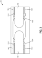
- FIG. 3 is a side view of the hinge 106 of FIG. 1 .
- the first portion 102 includes a first bumper 112-1 connected to a first upper surface 108-1 and a second bumper 112-2 connected to a first lower surface 110-1.
- the second portion 104 includes a third bumper 112-3 connected to a second upper surface 108-2 and a fourth bumper 112-4 connected to a second lower surface 110-2.
- the first portion 102 and the second portion 104 may have a bumper between them and the hinge body 114 for all directions of rotation. This helps to protect the first portion 102 and/or the second portion 104 from damage regardless of the position the computing device is in when it is dropped.
- each bumper may also protect the hinge from deforming or breaking by cushioning the impact between the hinge and the relatively non-deformable portions 102 and 104.
- each bumper has the same dimensions as each other bumper.
- at least one bumper has a distinct shape and/or size as compared to other bumpers.
- a subset of the bumpers is sized to act as feet for the device (e.g., to extend beyond a surface of the corresponding portion).
- FIG. 3 shows the bumpers 112 adhered to the portions 102 and 104, in other embodiments, one or more of the bumpers are instead adhered to the hinge body 114.
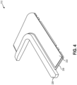
- FIG. 4 is a representation of a bumper assembly 212, according to at least one embodiment of the present disclosure.
- the bumper assembly 212 includes an impact resistant material 228 (e.g., a deformable material such as rubber).
- the impact resistant material 228 is bonded to a connecting member 230.
- the connecting member 230 is sized and configured to extend underneath a corresponding surface (e.g., the first upper surface 108-1 or the first lower surface 110-1 of FIG. 1 ) of the first or second portion to connect the impact resistant material 228 to the portion.
- the connecting member 230 may be adhered to the first portion using an adhesive layer 232. Connecting the impact resistant material 228 to the first portion using a connecting member 230 may help to increase the strength of the connection, thereby working to prevent the impact resistant material from breaking or tearing away.
- FIG. 5 is a bottom view of a bumper assembly 312, according to at least one embodiment of the present disclosure.
- the connecting member 330 has a connecting profile 334 that runs along the side of the connecting member 330 to which the impact resistant material 328 is connected.
- the connecting profile 334 includes one or more features 336.
- the features 336 may be cut-outs or protrusions in the connecting profile 334 that strengthen the mechanical strength of the connection between the impact resistant material 328 and the connecting member 330.
- the features 336 may include surface features, such as knurling, cross-hatching, and other surface features.
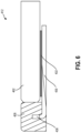
- FIG. 6 is a representation of a cross sectional view of a bumper assembly 412, not forming part of the invention but representing background art that is useful for understanding the invention.
- the connecting member 430 includes a lip 438.
- the lip 438 is a bend in the connecting member 430 that increases the mechanical strength of the connection between the impact resistant material 428 and the connecting member 430.
- the impact resistant material 428 is molded to the connecting member 430.
- the impact resistant material 428 may be overmolded (such as through injection molding or another process) over the connecting member 430. This may allow the impact resistant material 428 to match to contours of the connecting member 430.
- the impact resistant material 428 is secured to the first portion 402 through the connecting member 430.
- the connecting member 430 is secured to the first portion 402 using an adhesive layer 432.
- the impact resistant material 428 is contacting the first portion 402.
- the impact resistant material may be adhered to the first portion 402.
- FIG. 7 is a representation of a side view bumper assembly 512, according to at least one embodiment of the present disclosure.
- the impact resistant material 528 e.g., bumper 112 extends beyond the surface 540 of the portion 502 (e.g., the first portion 102 or the second portion 104).
- a first subset of the bumpers 112 are sized to extend beyond the corresponding portion surfaces while a second subset of the bumpers are sized to not extend (e.g., be flush with) the corresponding portion surfaces.
- the bumpers that would contact a resting surface when the device is oriented in a laptop mode would be sized to extend beyond the corresponding surface, while the other bumpers would be not extend beyond their corresponding portion surfaces.
- Having the material 528 extend beyond the surface of the portion 502 may further help to protect the portion 502 from cracking, scratching, deforming, and/or breaking. Furthermore, this provides the portion 502 with a "foot," or a support on which the computing device may rest when placed down on a support surface so that the surface 540 does not contact the support surface. This may help to prevent the surface 540 from being scratched, cracked, or broken.
- the bumper 112 is optionally adapted (e.g., textured and/or sized) to provide a desired coefficient of friction (CoF) between the device and a resting surface. In this way, the bumper 112 helps prevent the device from sliding during use and/or when the user is attempting to open the device.
- CoF coefficient of friction
- the impact resistant material 528 extends an extension height 542 beyond the surface 540.
- the extension height 542 may be in a range having an upper value, a lower value, or upper and lower values including any of 0.05 mm, 0.1 mm, 0.15 mm, 0.20 mm, 0.25 mm, 0.30 mm, 0.35 mm, 0.40 mm, 0.50 mm, 0.60 mm, 0.70 mm, 0.80 mm, 0.90 mm, 1.00 mm, or any value therebetween.
- the extension height 542 may be greater than 0.05 mm. In another example, the extension height 542 may be less than 1.00 mm.
- the extension height 542 may be any value in a range between 0.05 mm and 1.0 mm. In some embodiments, it may be critical that the extension height 542 is greater than 0.30 mm to provide protection for the surface 540 of the first portion 502. In some embodiments, the impact resistant material 528 is sized such that the extension height is greater than a deformation factor for the material so that the corresponding portion does not contact the resting surface even when a user is operating the device and providing a downward force on the device (e.g., due to the user resting their hands the device). In some embodiments, the extension height may be greater than 1.0 mm.
- a computing device includes a first portion and a second portion that are connected by one or more hinges.
- the first portion and the second portion may include one or more of glass covers, plastic covers, displays, ceramic plates, aluminum plates, magnesium plates, or any other plate, material, or cover.
- the hinge may be made from a steel alloy, aluminum, plastic, or other material.
- the one or more hinges may facilitate relative rotation between the first portion and the second portion.
- the one or more hinges may both rotate and translate relative to the first portion and/or the second portion.
- a rotating and a translating hinge facilitates an increased range of motion between the first portion and the second portion.
- the first portion may include a first top side and a first bottom side
- the second portion may include a second top side and a second bottom side. In a first position, the first bottom side may be parallel (and even contact) the second bottom side, and in a second position the first top side may be parallel (and even contact) the second top side.
- the first portion may be more brittle than the hinge.
- the first portion may break or crack. This may reduce functionality of a device by interfering with the view of a display, interfering with the sensitivity of a touch screen display, causing the first portion to separate from the hinge, cause some other reduction in functionality, and combinations of the foregoing.
- a broken or cracked first portion may be aesthetically unappealing to the user.
- the first portion may have a greater compressive strength than the hinge, which may cause the hinge to bend, crack, or break upon contact with the first portion. This may cause the hinge to malfunction and/or be aesthetically unappealing to the user.
- the first portion and/or the second portion may be both more brittle and have a harder compressive strength than the hinge. In this manner, a contact between the first portion and the hinge may damage, crack, break, or bend both the first portion and the hinge.
- an impact resistant member is affixed to the first portion.
- the impact resistant member may contact the hinge before the hinge contacts the first portion.
- the impact resistant member may be made from a material that is more resilient and/or have a greater elastic deformity than one or both of the first portion and the hinge. Thus, when the hinge would normally contact the first portion during rotation of the first portion, the hinge may contact the impact resistant layer. Because the impact resistant member has a greater resilience and/or elastic deformity, the impact resistant member may not break upon contact with the hinge. Thus, the impact resistant member may absorb the force of the impact from the hinge, thereby at least partially protecting (e.g., reducing the damage to) both the first portion and the hinge.
- the impact resistant member may be fabricated from a material that has a lower compressive strength than both the first portion and the hinge.
- the impact resistant member may be fabricated from, rubber, silicone, plastic, TPE, any other material, and combinations thereof.
- the impact resistant member may be attached to a connecting member, and the connecting member may be attached to the first portion.
- the connecting member may be a hard plate that is adhered to the second side of the first portion with an adhesive layer. The metal plate may extend past an edge of the first portion. The impact resistant member may then be connected to the connecting member.
- the impact resistant member may be overmolded onto the connecting member.
- a chemical primer may attached to the connecting member, and the chemical primer may further bond the impact resistant member to the connecting member.
- the impact resistant member and the connecting member may become a single piece. In other words, the impact resistant member may not be removed from the connecting member without damaging or destroying the impact resistant member and/or the connecting member.
- the connecting member may include mechanical interlock features, such as texturing, braiding, profiles, cross-hatching, knurling, other mechanical interlock features, and combinations of the foregoing.
- the connecting member may include an edge having an edge profile, the edge profile being non-straight. These mechanical interlock features may increase the strength of the bond between the impact resistant member and the connecting member.
- the connecting member may include a lip in the hinge area around which the impact resistant member is attached or molded. This lip may increase the strength of the impact resistant member and the resistance of the impact resistant member to damage and deformation from impact by the hinge.
- the impact resistant member may be attached directly to the first portion.
- the impact resistant member may be glued or molded onto the first portion.
- the first portion may include mechanical interlock features, such as texturing, braiding, profiles, cross-hatching, knurling, other mechanical interlock features, and combinations of the foregoing.
- the mechanical interlock features may be included in the first portion during manufacturing.
- the mechanical interlock features may be included in the first portion post manufacturing, such as by grinding, milling, laser etching, other methods, and combinations thereof.
- the impact resistant member may be connected directly to the hinge.
- the impact resistant member may be overmolded onto, or adhered to, an outer circumference of the hinge. In some embodiments, it may be aesthetically preferable to attach the impact resistant member directly to the hinge.
- the impact resistant member extends proud above a height of the first portion. In other words, the impact resistant member may extend beyond the first surface of the first portion. In this manner, the impact resistant member may resemble a foot against which the mobile device may rest. This may help to protect the first portion from scratches, cracks, breaks, and other damage caused by a user placing the mobile device on a surface.
- the extension past the first surface may be in a range having an upper value, a lower value, or upper and lower values including any of 0.05 mm, 0.1 mm, 0.15 mm, 0.20 mm, 0.25 mm, 0.30 mm, 0.35 mm, 0.40 mm, 0.50 mm, 0.60 mm, 0.70 mm, 0.80 mm, 0.90 mm, 1.00 mm, or any value therebetween.
- the extension may be greater than 0.05 mm.
- the extension may be less than 1.0 mm.
- the extension may be any value in a range between 0.05 mm and 1.0 mm.
- it may be critical that the extension is greater than 0.30 mm to properly protect the first surface.
- the extension may be greater than 1.0 mm.
- the first portion has a hinge profile, which is the profile of the first portion around the hinge.
- the profile is offset from the range of motion of the hinge with a profile offset.
- the impact resistant member may be placed inside the profile offset. In this manner, the impact resistant member may extend from the profile of the first portion to the range of motion of the hinge. This may reduce the visible or spatial gap between the first portion and the hinge, which may be visually appealing to the user.
- the profile includes at least one corner having a first portion radius of curvature.
- the first portion radius of curvature of the profile may be increased by offsetting the profile from the hinge. This may reduce the stress concentrations on the first portion. This may reduce the likelihood that the first portion may break or crack at the corner.
- the first portion radius of curvature may be greater than 0 mm.
- the radius of curvature may be greater than 0.1 mm, 0.2 mm, 0.3 mm, 0.4 mm, 0.5 mm, 0.6 mm, 0.7 mm, 0.8 mm, 0.9 mm, 1.0 mm, or any value therebetween.
- it may be critical that the first portion radius of curvature is greater than 0.5 mm to reduce the likelihood of the first portion cracking.
- the impact resistant member may follow the profile of the first portion.
- the impact resistant member may thus have an impact resistant member radius of curvature that is less than the first portion radius of curvature.
- the impact radius of curvature may be approximately 0. In other words, the impact resistant member may make one or more sharp turns.
- Numbers, percentages, ratios, or other values stated herein are intended to include that value, and also other values that are “about” or “approximately” the stated value, as would be appreciated by one of ordinary skill in the art encompassed by embodiments of the present disclosure.
- a stated value should therefore be interpreted broadly enough to encompass values that are at least close enough to the stated value to perform a desired function or achieve a desired result.
- the stated values include at least the variation to be expected in a suitable manufacturing or production process, and may include values that are within 5%, within 1%, within 0.1%, or within 0.01% of a stated value.
- any directions or reference frames in the preceding description are merely relative directions or movements.
- any references to “up” and “down” or “above” or “below” are merely descriptive of the relative position or movement of the related elements.
- the described embodiments are to be considered as illustrative and not restrictive. The scope of the invention is, therefore, indicated by the appended claims rather than by the foregoing description.
Landscapes
- Engineering & Computer Science (AREA)
- Computer Hardware Design (AREA)
- Theoretical Computer Science (AREA)
- Physics & Mathematics (AREA)
- General Engineering & Computer Science (AREA)
- Human Computer Interaction (AREA)
- General Physics & Mathematics (AREA)
- Signal Processing (AREA)
- Mathematical Physics (AREA)
- Microelectronics & Electronic Packaging (AREA)
- Casings For Electric Apparatus (AREA)
Claims (14)
- Un dispositif informatique, comprenant :une première portion (102, 402) ;une deuxième portion (104) ;une articulation rotative et translative (106, 114) raccordant la première portion à la deuxième portion ;un élément résistant aux chocs (112, 212, 312, 412) fixé à la première portion (402), l'élément résistant aux chocs (112, 212, 312, 412) s'étendant en saillie au-dessus d'une hauteur de la première portion (102, 402) ;caractérisé en ce que :
l'élément résistant aux chocs (112, 212, 312, 412) est placé entre l'articulation rotative et translative (106) et la première portion (102) de telle sorte que l'articulation rotative et translative est au contact de l'élément résistant aux chocs (112, 212, 412) dans une configuration de choc. - Le dispositif informatique de la revendication 1, comprenant en sus un élément de raccordement (230, 330, 430) collé à une première surface (108-1, 110-1) de la première portion.
- Le dispositif informatique de la revendication 2, l'élément résistant aux chocs (212, 312) étant assujetti à l'élément de raccordement.
- Le dispositif informatique de la revendication 3, l'élément résistant aux chocs (212, 312) s'étendant en saillie au-dessus d'une deuxième surface de la première portion, la deuxième surface étant opposée à la première surface.
- Le dispositif informatique de n'importe lesquelles des revendications 2 à 4, l'élément de raccordement (230, 330, 430) étant collé à la première surface avec un adhésif.
- Le dispositif informatique de n'importe lesquelles des revendications 1 à 5, dans lequel l'articulation rotative et translative (106) inclut une pluralité d'articulations rotatives et translatives (106) raccordant la première portion à la deuxième portion.
- Le dispositif informatique de n'importe lesquelles des revendications 1 à 6, dans lequel la première portion (102) inclut un profil (116) présentant un coin avec un rayon de courbure de première portion, et dans lequel l'élément résistant aux chocs suit le profil de la première portion, l'élément résistant aux chocs présentant un rayon de courbure d'élément résistant aux chocs qui est nul, et dans lequel le rayon de courbure de première portion est supérieur à 0,5 mm.
- Le dispositif informatique de n'importe lesquelles des revendications 1 à 7, dans lequel l'élément résistant aux chocs (112) est un premier élément résistant aux chocs, et comprenant en sus un deuxième élément résistant aux chocs, et dans lequel le deuxième élément résistant aux chocs (112) est raccordé à la deuxième portion et s'étend en saillie au-dessus d'une deuxième hauteur de la deuxième portion.
- Un dispositif informatique, comprenant :une première portion (102) et une deuxième portion (104) ;une articulation rotative et translative (106) raccordant la première portion à la deuxième portion ; etun élément résistant aux chocs (112) fixé à l'articulation rotative et translative, l'élément résistant aux chocs s'étendant en saillie au-dessus d'une hauteur de la première portion dans une configuration fermée ;caractérisé en ce que :
l'élément résistant aux chocs (112) est placé entre l'articulation rotative et translative (106) et la première portion (102) de telle sorte que la première portion est au contact de l'élément résistant aux chocs dans une configuration de choc. - Le dispositif informatique de la revendication 9, dans lequel l'élément résistant aux chocs est fixé autour d'une intégralité d'une circonférence de l'articulation rotative et translative.
- Le dispositif informatique de la revendication 9 ou de la revendication 10, dans lequel l'élément résistant aux chocs est formé en un matériau qui est plus déformable élastiquement qu'à la fois la première portion et l'articulation rotative et translative.
- Le dispositif informatique de n'importe lesquelles des revendications 9 à 11, dans lequel la première portion (102) présente une première résistance à la compression qui est inférieure d'au moins 50 GPa à une résistance à la compression d'articulation de l'articulation rotative et translative (106).
- Le dispositif informatique de n'importe lesquelles des revendications 9 à 12, dans lequel la première portion (102) présente une dureté Mohs qui est supérieure à celle de l'articulation rotative et translative (106).
- Le dispositif informatique de n'importe lesquelles des revendications 1 à 13, dans lequel l'élément résistant aux chocs (112) empêche l'articulation rotative et translative (106), dans une position en surextension, d'être au contact de la première portion (102).
Applications Claiming Priority (3)
| Application Number | Priority Date | Filing Date | Title |
|---|---|---|---|
| US201962908987P | 2019-10-01 | 2019-10-01 | |
| US16/855,848 US11219135B2 (en) | 2019-10-01 | 2020-04-22 | Impact resistant hinge |
| PCT/US2020/048069 WO2021066967A1 (fr) | 2019-10-01 | 2020-08-27 | Charnière résistant aux chocs |
Publications (2)
| Publication Number | Publication Date |
|---|---|
| EP4038471A1 EP4038471A1 (fr) | 2022-08-10 |
| EP4038471B1 true EP4038471B1 (fr) | 2025-06-11 |
Family
ID=75162659
Family Applications (1)
| Application Number | Title | Priority Date | Filing Date |
|---|---|---|---|
| EP20768220.4A Active EP4038471B1 (fr) | 2019-10-01 | 2020-08-27 | Charnière résistant aux chocs |
Country Status (4)
| Country | Link |
|---|---|
| US (2) | US11219135B2 (fr) |
| EP (1) | EP4038471B1 (fr) |
| CN (1) | CN114467069B (fr) |
| WO (1) | WO2021066967A1 (fr) |
Families Citing this family (2)
| Publication number | Priority date | Publication date | Assignee | Title |
|---|---|---|---|---|
| US11219135B2 (en) * | 2019-10-01 | 2022-01-04 | Microsoft Technology Licensing, Llc | Impact resistant hinge |
| CN119042276A (zh) * | 2022-07-01 | 2024-11-29 | 荣耀终端有限公司 | 折叠组件及折叠式显示设备 |
Family Cites Families (30)
| Publication number | Priority date | Publication date | Assignee | Title |
|---|---|---|---|---|
| US6251493B1 (en) * | 1996-04-08 | 2001-06-26 | 3M Innovative Properties Company | Vibration and shock attenuating articles and method of attenuating vibrations and shocks therewith |
| US6831229B1 (en) | 2003-09-11 | 2004-12-14 | Nokia Corporation | Hinge cover mechanism for folding casings with lift function |
| KR100524682B1 (ko) | 2003-11-10 | 2005-11-01 | 엘지전자 주식회사 | 폴더형 휴대폰의 개폐충격 완화장치 |
| KR20050055191A (ko) | 2003-12-05 | 2005-06-13 | 주식회사 팬택앤큐리텔 | 폴더형 이동통신 단말기 |
| JP2006053629A (ja) * | 2004-08-10 | 2006-02-23 | Toshiba Corp | 電子機器、制御方法及び制御プログラム |
| US7189972B2 (en) * | 2004-10-04 | 2007-03-13 | General Electric Company | X-ray detector with impact absorbing cover |
| US20060089182A1 (en) * | 2004-10-21 | 2006-04-27 | Nokia Corporation | Elastomeric tensioner and mobile stations using same |
| US7566877B2 (en) * | 2005-01-28 | 2009-07-28 | Vivek Bhatt | Systems, methods, and apparatus for a kinetic energy absorbing device |
| US20070097014A1 (en) * | 2005-10-31 | 2007-05-03 | Solomon Mark C | Electronic device with flexible display screen |
| TWI468897B (zh) | 2007-04-25 | 2015-01-11 | Creator Technology Bv | 電子裝置 |
| JP2011070488A (ja) * | 2009-09-28 | 2011-04-07 | Panasonic Corp | 情報処理装置 |
| JP2012185797A (ja) | 2011-02-15 | 2012-09-27 | Toshiba Corp | 電子機器 |
| US8699212B2 (en) * | 2011-07-12 | 2014-04-15 | Lionel Galerne | Electronic reading apparatus, method and system for use in hyperbaric and hypobaric conditions |
| TWI504336B (zh) * | 2013-07-05 | 2015-10-11 | Pegatron Corp | 轉軸模組及使用其之電子裝置 |
| US10227808B2 (en) * | 2015-11-20 | 2019-03-12 | Microsoft Technology Licensing, Llc | Hinged device |
| US9625950B1 (en) | 2016-03-21 | 2017-04-18 | Max Interactive, Inc. | Protective cover for convertible laptop and tablet |
| US10488882B2 (en) * | 2016-09-02 | 2019-11-26 | Microsoft Technology Licensing, Llc | Electronic device hinge assembly |
| US10364598B2 (en) * | 2016-09-02 | 2019-07-30 | Microsoft Technology Licensing, Llc | Hinged device |
| US10627857B2 (en) * | 2016-11-01 | 2020-04-21 | Lenovo (Singapore) Pte. Ltd. | Electronic device with rotatable and translational display unit |
| US10795416B2 (en) * | 2017-09-22 | 2020-10-06 | Microsoft Technology Licensing, Llc | Hinged device |
| CN109871067B (zh) * | 2017-12-01 | 2022-12-06 | 宏碁股份有限公司 | 转轴模块与电子装置 |
| US10571977B2 (en) * | 2017-12-26 | 2020-02-25 | Intel Corporation | Technologies for hinges for dual screen devices |
| US10890949B2 (en) * | 2018-10-12 | 2021-01-12 | Google Llc | Hinge mechanism by gear set with slider for foldable display device |
| US10469635B1 (en) * | 2019-01-23 | 2019-11-05 | Motorola Mobility Llc | Hinged electronic device with chambers accommodating a dynamic flexible substrate and corresponding systems |
| JP6739590B1 (ja) * | 2019-05-20 | 2020-08-12 | レノボ・シンガポール・プライベート・リミテッド | 電子機器 |
| BR112021023955B1 (pt) * | 2019-05-31 | 2024-03-05 | Samsung Electronics Co., Ltd | Dispositivo eletrônico dobrável incluindo estrutura de proteção de exibidor |
| US20210089077A1 (en) * | 2019-09-23 | 2021-03-25 | Apple Inc. | Deployable feet for display articulation and thermals performance |
| US11219135B2 (en) * | 2019-10-01 | 2022-01-04 | Microsoft Technology Licensing, Llc | Impact resistant hinge |
| US11147169B2 (en) * | 2019-11-04 | 2021-10-12 | Sharp Kabushiki Kaisha | Impact absorbing element for display device |
| KR20230080734A (ko) * | 2021-11-30 | 2023-06-07 | 삼성전자주식회사 | 디스플레이 보호 구조를 포함하는 전자 장치 |
-
2020
- 2020-04-22 US US16/855,848 patent/US11219135B2/en active Active
- 2020-08-27 WO PCT/US2020/048069 patent/WO2021066967A1/fr not_active Ceased
- 2020-08-27 EP EP20768220.4A patent/EP4038471B1/fr active Active
- 2020-08-27 CN CN202080069834.1A patent/CN114467069B/zh active Active
-
2022
- 2022-01-03 US US17/567,819 patent/US11943885B2/en active Active
Also Published As
| Publication number | Publication date |
|---|---|
| US11219135B2 (en) | 2022-01-04 |
| CN114467069B (zh) | 2024-08-13 |
| US11943885B2 (en) | 2024-03-26 |
| CN114467069A (zh) | 2022-05-10 |
| EP4038471A1 (fr) | 2022-08-10 |
| US20220183170A1 (en) | 2022-06-09 |
| US20210100118A1 (en) | 2021-04-01 |
| WO2021066967A1 (fr) | 2021-04-08 |
Similar Documents
| Publication | Publication Date | Title |
|---|---|---|
| EP4038471B1 (fr) | Charnière résistant aux chocs | |
| EP3729991B1 (fr) | Structure de boîtier | |
| JP5007751B2 (ja) | 腕時計 | |
| US6262886B1 (en) | Translucent protective covering for a computer housing | |
| US7382607B2 (en) | Housing for a portable computing device | |
| EP2562439B1 (fr) | Dispositif d'isolation sismique | |
| JP6873912B2 (ja) | 薄いフォームファクタで低コスト設計を可能にするファスナレスヒンジ | |
| CN104576152A (zh) | 输入装置及其软性保护盖 | |
| US20200095026A1 (en) | Container | |
| WO2018044585A1 (fr) | Systèmes et procédés d'intégration d'affichage | |
| US12022925B2 (en) | Case for an electronic device | |
| EP1925998A2 (fr) | Boîte de montre | |
| CN210807886U (zh) | 电子装置 | |
| CN212686347U (zh) | 玻璃贴的防护构造 | |
| TW202242934A (zh) | 按鍵及其按鍵連接組件 | |
| CN223567663U (zh) | 保护壳 | |
| JP5639379B2 (ja) | 弾性滑り支承構造体 | |
| JP2019144026A (ja) | 腕時計の風防又は画面用のカバーシート | |
| US20250036163A1 (en) | Protective trims for electronic devices | |
| CA3036569C (fr) | Coque pour un dispositif electronique | |
| US20250271812A1 (en) | Device case and timepiece | |
| CN215927103U (zh) | 一种定位玻璃合页 | |
| JP5712565B2 (ja) | ショーケースの前面扉構造 | |
| CN209330198U (zh) | 一种减震手机壳 | |
| TW202414472A (zh) | 具有快速安裝特性的按鍵及其鍵盤 |
Legal Events
| Date | Code | Title | Description |
|---|---|---|---|
| STAA | Information on the status of an ep patent application or granted ep patent |
Free format text: STATUS: UNKNOWN |
|
| STAA | Information on the status of an ep patent application or granted ep patent |
Free format text: STATUS: THE INTERNATIONAL PUBLICATION HAS BEEN MADE |
|
| PUAI | Public reference made under article 153(3) epc to a published international application that has entered the european phase |
Free format text: ORIGINAL CODE: 0009012 |
|
| STAA | Information on the status of an ep patent application or granted ep patent |
Free format text: STATUS: REQUEST FOR EXAMINATION WAS MADE |
|
| 17P | Request for examination filed |
Effective date: 20220328 |
|
| AK | Designated contracting states |
Kind code of ref document: A1 Designated state(s): AL AT BE BG CH CY CZ DE DK EE ES FI FR GB GR HR HU IE IS IT LI LT LU LV MC MK MT NL NO PL PT RO RS SE SI SK SM TR |
|
| DAV | Request for validation of the european patent (deleted) | ||
| DAX | Request for extension of the european patent (deleted) | ||
| STAA | Information on the status of an ep patent application or granted ep patent |
Free format text: STATUS: EXAMINATION IS IN PROGRESS |
|
| 17Q | First examination report despatched |
Effective date: 20240430 |
|
| GRAP | Despatch of communication of intention to grant a patent |
Free format text: ORIGINAL CODE: EPIDOSNIGR1 |
|
| STAA | Information on the status of an ep patent application or granted ep patent |
Free format text: STATUS: GRANT OF PATENT IS INTENDED |
|
| INTG | Intention to grant announced |
Effective date: 20250120 |
|
| GRAS | Grant fee paid |
Free format text: ORIGINAL CODE: EPIDOSNIGR3 |
|
| GRAA | (expected) grant |
Free format text: ORIGINAL CODE: 0009210 |
|
| STAA | Information on the status of an ep patent application or granted ep patent |
Free format text: STATUS: THE PATENT HAS BEEN GRANTED |
|
| P01 | Opt-out of the competence of the unified patent court (upc) registered |
Free format text: CASE NUMBER: APP_19343/2025 Effective date: 20250423 |
|
| AK | Designated contracting states |
Kind code of ref document: B1 Designated state(s): AL AT BE BG CH CY CZ DE DK EE ES FI FR GB GR HR HU IE IS IT LI LT LU LV MC MK MT NL NO PL PT RO RS SE SI SK SM TR |
|
| REG | Reference to a national code |
Ref country code: GB Ref legal event code: FG4D |
|
| REG | Reference to a national code |
Ref country code: CH Ref legal event code: EP |
|
| REG | Reference to a national code |
Ref country code: DE Ref legal event code: R096 Ref document number: 602020052638 Country of ref document: DE |
|
| REG | Reference to a national code |
Ref country code: IE Ref legal event code: FG4D |
|
| PG25 | Lapsed in a contracting state [announced via postgrant information from national office to epo] |
Ref country code: FI Free format text: LAPSE BECAUSE OF FAILURE TO SUBMIT A TRANSLATION OF THE DESCRIPTION OR TO PAY THE FEE WITHIN THE PRESCRIBED TIME-LIMIT Effective date: 20250611 Ref country code: ES Free format text: LAPSE BECAUSE OF FAILURE TO SUBMIT A TRANSLATION OF THE DESCRIPTION OR TO PAY THE FEE WITHIN THE PRESCRIBED TIME-LIMIT Effective date: 20250611 |
|
| PGFP | Annual fee paid to national office [announced via postgrant information from national office to epo] |
Ref country code: DE Payment date: 20250724 Year of fee payment: 6 |
|
| REG | Reference to a national code |
Ref country code: LT Ref legal event code: MG9D |
|
| PG25 | Lapsed in a contracting state [announced via postgrant information from national office to epo] |
Ref country code: NO Free format text: LAPSE BECAUSE OF FAILURE TO SUBMIT A TRANSLATION OF THE DESCRIPTION OR TO PAY THE FEE WITHIN THE PRESCRIBED TIME-LIMIT Effective date: 20250911 Ref country code: GR Free format text: LAPSE BECAUSE OF FAILURE TO SUBMIT A TRANSLATION OF THE DESCRIPTION OR TO PAY THE FEE WITHIN THE PRESCRIBED TIME-LIMIT Effective date: 20250912 |
|
| REG | Reference to a national code |
Ref country code: NL Ref legal event code: MP Effective date: 20250611 |
|
| PG25 | Lapsed in a contracting state [announced via postgrant information from national office to epo] |
Ref country code: BG Free format text: LAPSE BECAUSE OF FAILURE TO SUBMIT A TRANSLATION OF THE DESCRIPTION OR TO PAY THE FEE WITHIN THE PRESCRIBED TIME-LIMIT Effective date: 20250611 |
|
| PGFP | Annual fee paid to national office [announced via postgrant information from national office to epo] |
Ref country code: GB Payment date: 20250724 Year of fee payment: 6 |
|
| PG25 | Lapsed in a contracting state [announced via postgrant information from national office to epo] |
Ref country code: HR Free format text: LAPSE BECAUSE OF FAILURE TO SUBMIT A TRANSLATION OF THE DESCRIPTION OR TO PAY THE FEE WITHIN THE PRESCRIBED TIME-LIMIT Effective date: 20250611 |
|
| PG25 | Lapsed in a contracting state [announced via postgrant information from national office to epo] |
Ref country code: RS Free format text: LAPSE BECAUSE OF FAILURE TO SUBMIT A TRANSLATION OF THE DESCRIPTION OR TO PAY THE FEE WITHIN THE PRESCRIBED TIME-LIMIT Effective date: 20250911 |
|
| PG25 | Lapsed in a contracting state [announced via postgrant information from national office to epo] |
Ref country code: LV Free format text: LAPSE BECAUSE OF FAILURE TO SUBMIT A TRANSLATION OF THE DESCRIPTION OR TO PAY THE FEE WITHIN THE PRESCRIBED TIME-LIMIT Effective date: 20250611 |
|
| PG25 | Lapsed in a contracting state [announced via postgrant information from national office to epo] |
Ref country code: NL Free format text: LAPSE BECAUSE OF FAILURE TO SUBMIT A TRANSLATION OF THE DESCRIPTION OR TO PAY THE FEE WITHIN THE PRESCRIBED TIME-LIMIT Effective date: 20250611 |
|
| PG25 | Lapsed in a contracting state [announced via postgrant information from national office to epo] |
Ref country code: PT Free format text: LAPSE BECAUSE OF FAILURE TO SUBMIT A TRANSLATION OF THE DESCRIPTION OR TO PAY THE FEE WITHIN THE PRESCRIBED TIME-LIMIT Effective date: 20251013 |
|
| REG | Reference to a national code |
Ref country code: AT Ref legal event code: MK05 Ref document number: 1802767 Country of ref document: AT Kind code of ref document: T Effective date: 20250611 |
|
| PG25 | Lapsed in a contracting state [announced via postgrant information from national office to epo] |
Ref country code: IS Free format text: LAPSE BECAUSE OF FAILURE TO SUBMIT A TRANSLATION OF THE DESCRIPTION OR TO PAY THE FEE WITHIN THE PRESCRIBED TIME-LIMIT Effective date: 20251011 |
|
| PG25 | Lapsed in a contracting state [announced via postgrant information from national office to epo] |
Ref country code: AT Free format text: LAPSE BECAUSE OF FAILURE TO SUBMIT A TRANSLATION OF THE DESCRIPTION OR TO PAY THE FEE WITHIN THE PRESCRIBED TIME-LIMIT Effective date: 20250611 Ref country code: SM Free format text: LAPSE BECAUSE OF FAILURE TO SUBMIT A TRANSLATION OF THE DESCRIPTION OR TO PAY THE FEE WITHIN THE PRESCRIBED TIME-LIMIT Effective date: 20250611 |
|
| PG25 | Lapsed in a contracting state [announced via postgrant information from national office to epo] |
Ref country code: CZ Free format text: LAPSE BECAUSE OF FAILURE TO SUBMIT A TRANSLATION OF THE DESCRIPTION OR TO PAY THE FEE WITHIN THE PRESCRIBED TIME-LIMIT Effective date: 20250611 |
|
| PG25 | Lapsed in a contracting state [announced via postgrant information from national office to epo] |
Ref country code: PL Free format text: LAPSE BECAUSE OF FAILURE TO SUBMIT A TRANSLATION OF THE DESCRIPTION OR TO PAY THE FEE WITHIN THE PRESCRIBED TIME-LIMIT Effective date: 20250611 |
|
| PG25 | Lapsed in a contracting state [announced via postgrant information from national office to epo] |
Ref country code: EE Free format text: LAPSE BECAUSE OF FAILURE TO SUBMIT A TRANSLATION OF THE DESCRIPTION OR TO PAY THE FEE WITHIN THE PRESCRIBED TIME-LIMIT Effective date: 20250611 |
|
| PG25 | Lapsed in a contracting state [announced via postgrant information from national office to epo] |
Ref country code: SK Free format text: LAPSE BECAUSE OF FAILURE TO SUBMIT A TRANSLATION OF THE DESCRIPTION OR TO PAY THE FEE WITHIN THE PRESCRIBED TIME-LIMIT Effective date: 20250611 |
|
| PG25 | Lapsed in a contracting state [announced via postgrant information from national office to epo] |
Ref country code: RO Free format text: LAPSE BECAUSE OF FAILURE TO SUBMIT A TRANSLATION OF THE DESCRIPTION OR TO PAY THE FEE WITHIN THE PRESCRIBED TIME-LIMIT Effective date: 20250611 |
|
| REG | Reference to a national code |
Ref country code: CH Ref legal event code: H13 Free format text: ST27 STATUS EVENT CODE: U-0-0-H10-H13 (AS PROVIDED BY THE NATIONAL OFFICE) Effective date: 20260324 |
|
| PG25 | Lapsed in a contracting state [announced via postgrant information from national office to epo] |
Ref country code: MC Free format text: LAPSE BECAUSE OF FAILURE TO SUBMIT A TRANSLATION OF THE DESCRIPTION OR TO PAY THE FEE WITHIN THE PRESCRIBED TIME-LIMIT Effective date: 20250611 |
|
| PG25 | Lapsed in a contracting state [announced via postgrant information from national office to epo] |
Ref country code: DK Free format text: LAPSE BECAUSE OF FAILURE TO SUBMIT A TRANSLATION OF THE DESCRIPTION OR TO PAY THE FEE WITHIN THE PRESCRIBED TIME-LIMIT Effective date: 20250611 |
|
| PG25 | Lapsed in a contracting state [announced via postgrant information from national office to epo] |
Ref country code: LU Free format text: LAPSE BECAUSE OF NON-PAYMENT OF DUE FEES Effective date: 20250827 Ref country code: IT Free format text: LAPSE BECAUSE OF FAILURE TO SUBMIT A TRANSLATION OF THE DESCRIPTION OR TO PAY THE FEE WITHIN THE PRESCRIBED TIME-LIMIT Effective date: 20250611 |
|
| PLBE | No opposition filed within time limit |
Free format text: ORIGINAL CODE: 0009261 |
|
| STAA | Information on the status of an ep patent application or granted ep patent |
Free format text: STATUS: NO OPPOSITION FILED WITHIN TIME LIMIT |
|
| REG | Reference to a national code |
Ref country code: CH Ref legal event code: L10 Free format text: ST27 STATUS EVENT CODE: U-0-0-L10-L00 (AS PROVIDED BY THE NATIONAL OFFICE) Effective date: 20260423 |