EP4039083B1 - Blasgerät - Google Patents
Blasgerät Download PDFInfo
- Publication number
- EP4039083B1 EP4039083B1 EP22151967.1A EP22151967A EP4039083B1 EP 4039083 B1 EP4039083 B1 EP 4039083B1 EP 22151967 A EP22151967 A EP 22151967A EP 4039083 B1 EP4039083 B1 EP 4039083B1
- Authority
- EP
- European Patent Office
- Prior art keywords
- blower
- motor
- circuit board
- control circuit
- inner ring
- Prior art date
- Legal status (The legal status is an assumption and is not a legal conclusion. Google has not performed a legal analysis and makes no representation as to the accuracy of the status listed.)
- Active
Links
Images


Classifications
-
- F—MECHANICAL ENGINEERING; LIGHTING; HEATING; WEAPONS; BLASTING
- F04—POSITIVE - DISPLACEMENT MACHINES FOR LIQUIDS; PUMPS FOR LIQUIDS OR ELASTIC FLUIDS
- F04D—NON-POSITIVE-DISPLACEMENT PUMPS
- F04D25/00—Pumping installations or systems
- F04D25/02—Units comprising pumps and their driving means
- F04D25/08—Units comprising pumps and their driving means the working fluid being air, e.g. for ventilation
-
- F—MECHANICAL ENGINEERING; LIGHTING; HEATING; WEAPONS; BLASTING
- F04—POSITIVE - DISPLACEMENT MACHINES FOR LIQUIDS; PUMPS FOR LIQUIDS OR ELASTIC FLUIDS
- F04D—NON-POSITIVE-DISPLACEMENT PUMPS
- F04D25/00—Pumping installations or systems
- F04D25/02—Units comprising pumps and their driving means
- F04D25/06—Units comprising pumps and their driving means the pump being electrically driven
-
- F—MECHANICAL ENGINEERING; LIGHTING; HEATING; WEAPONS; BLASTING
- F04—POSITIVE - DISPLACEMENT MACHINES FOR LIQUIDS; PUMPS FOR LIQUIDS OR ELASTIC FLUIDS
- F04D—NON-POSITIVE-DISPLACEMENT PUMPS
- F04D27/00—Control, e.g. regulation, of pumps, pumping installations or pumping systems specially adapted for elastic fluids
-
- F—MECHANICAL ENGINEERING; LIGHTING; HEATING; WEAPONS; BLASTING
- F04—POSITIVE - DISPLACEMENT MACHINES FOR LIQUIDS; PUMPS FOR LIQUIDS OR ELASTIC FLUIDS
- F04D—NON-POSITIVE-DISPLACEMENT PUMPS
- F04D29/00—Details, component parts, or accessories
- F04D29/002—Details, component parts, or accessories especially adapted for elastic fluid pumps
-
- F—MECHANICAL ENGINEERING; LIGHTING; HEATING; WEAPONS; BLASTING
- F04—POSITIVE - DISPLACEMENT MACHINES FOR LIQUIDS; PUMPS FOR LIQUIDS OR ELASTIC FLUIDS
- F04D—NON-POSITIVE-DISPLACEMENT PUMPS
- F04D29/00—Details, component parts, or accessories
- F04D29/40—Casings; Connections of working fluid
- F04D29/403—Casings; Connections of working fluid especially adapted for elastic fluid pumps
-
- F—MECHANICAL ENGINEERING; LIGHTING; HEATING; WEAPONS; BLASTING
- F04—POSITIVE - DISPLACEMENT MACHINES FOR LIQUIDS; PUMPS FOR LIQUIDS OR ELASTIC FLUIDS
- F04D—NON-POSITIVE-DISPLACEMENT PUMPS
- F04D29/00—Details, component parts, or accessories
- F04D29/40—Casings; Connections of working fluid
- F04D29/52—Casings; Connections of working fluid for axial pumps
- F04D29/522—Casings; Connections of working fluid for axial pumps especially adapted for elastic fluid pumps
-
- F—MECHANICAL ENGINEERING; LIGHTING; HEATING; WEAPONS; BLASTING
- F04—POSITIVE - DISPLACEMENT MACHINES FOR LIQUIDS; PUMPS FOR LIQUIDS OR ELASTIC FLUIDS
- F04D—NON-POSITIVE-DISPLACEMENT PUMPS
- F04D29/00—Details, component parts, or accessories
- F04D29/40—Casings; Connections of working fluid
- F04D29/52—Casings; Connections of working fluid for axial pumps
- F04D29/54—Fluid-guiding means, e.g. diffusers
- F04D29/541—Specially adapted for elastic fluid pumps
- F04D29/545—Ducts
-
- F—MECHANICAL ENGINEERING; LIGHTING; HEATING; WEAPONS; BLASTING
- F04—POSITIVE - DISPLACEMENT MACHINES FOR LIQUIDS; PUMPS FOR LIQUIDS OR ELASTIC FLUIDS
- F04D—NON-POSITIVE-DISPLACEMENT PUMPS
- F04D29/00—Details, component parts, or accessories
- F04D29/58—Cooling; Heating; Diminishing heat transfer
- F04D29/5806—Cooling the drive system
-
- F—MECHANICAL ENGINEERING; LIGHTING; HEATING; WEAPONS; BLASTING
- F04—POSITIVE - DISPLACEMENT MACHINES FOR LIQUIDS; PUMPS FOR LIQUIDS OR ELASTIC FLUIDS
- F04D—NON-POSITIVE-DISPLACEMENT PUMPS
- F04D29/00—Details, component parts, or accessories
- F04D29/58—Cooling; Heating; Diminishing heat transfer
- F04D29/5813—Cooling the control unit
-
- F—MECHANICAL ENGINEERING; LIGHTING; HEATING; WEAPONS; BLASTING
- F04—POSITIVE - DISPLACEMENT MACHINES FOR LIQUIDS; PUMPS FOR LIQUIDS OR ELASTIC FLUIDS
- F04D—NON-POSITIVE-DISPLACEMENT PUMPS
- F04D29/00—Details, component parts, or accessories
- F04D29/58—Cooling; Heating; Diminishing heat transfer
- F04D29/582—Cooling; Heating; Diminishing heat transfer specially adapted for elastic fluid pumps
-
- H—ELECTRICITY
- H05—ELECTRIC TECHNIQUES NOT OTHERWISE PROVIDED FOR
- H05K—PRINTED CIRCUITS; CASINGS OR CONSTRUCTIONAL DETAILS OF ELECTRIC APPARATUS; MANUFACTURE OF ASSEMBLAGES OF ELECTRICAL COMPONENTS
- H05K7/00—Constructional details common to different types of electric apparatus
- H05K7/20—Modifications to facilitate cooling, ventilating, or heating
- H05K7/20009—Modifications to facilitate cooling, ventilating, or heating using a gaseous coolant in electronic enclosures
- H05K7/20136—Forced ventilation, e.g. by fans
- H05K7/20145—Means for directing air flow, e.g. ducts, deflectors, plenum or guides
-
- A—HUMAN NECESSITIES
- A01—AGRICULTURE; FORESTRY; ANIMAL HUSBANDRY; HUNTING; TRAPPING; FISHING
- A01G—HORTICULTURE; CULTIVATION OF VEGETABLES, FLOWERS, RICE, FRUIT, VINES, HOPS OR SEAWEED; FORESTRY; WATERING
- A01G20/00—Cultivation of turf, lawn or the like; Apparatus or methods therefor
- A01G20/40—Apparatus for cleaning the lawn or grass surface
- A01G20/43—Apparatus for cleaning the lawn or grass surface for sweeping, collecting or disintegrating lawn debris
- A01G20/47—Vacuum or blower devices
Definitions
- the present invention relates to a blower, in particular to a blower for gardening work.
- Leaf blowers are mainly used for blowing away fallen leaves, road surface dust, accumulated water and accumulated snow, etc.
- Common types of blower include petrol blowers and electric blowers.
- a petrol blower is powered by a petrol engine; fan blades rotate inside a fan volute, producing a wind which blows out through an air outlet to perform a job.
- an electric blower in which the fan is driven to rotate by a motor is small in volume, light in weight and convenient to operate, and is therefore popular among consumers.
- a cooling mechanism comprises a heat sink mounted on the circuit board and an independent air channel for cooling, enabling external air to carry away heat from the circuit board and the heat sink.
- the heat sink increases the weight of the blower, and it is difficult to ensure that a sufficient quantity of cooling air enters the independent air channel.
- the US 6 105 206 A discloses a portable blower having a sound-insulated blower tube enclosing the electric motor and fan assembly, wherein the fan unit is positioned within a hollow support tube with openings on one or both ends for directing a forced convection cooling airflow to the brushless DC electric motor.
- the present invention provides a blower as defined by claim 1, which utilizes a working airflow generated by the fan when rotating to cool the circuit board.
- the blower comprises: a blower body, having accommodated therein a fan and a drive unit, a rotation shaft of the fan defining a longitudinal axis, and the blower body defining an air inlet; a blow pipe, attached to the blower body and extending along the longitudinal axis, the blow pipe defining an air outlet; a control unit, for controlling operation of the drive unit, wherein the blower defines an airflow path extending from the air inlet to the air outlet, the control unit being at least partially located in the airflow path, such that when the blower is operating, at least a portion of an airflow entering the air inlet cools the control unit and is then discharged through the air outlet.
- control unit is arranged close to the drive unit.
- control unit is substantially transverse to the longitudinal axis.
- the drive unit comprises a motor
- the control unit comprises a control circuit board located at an end of the motor.
- one of the control circuit board and the fan is located downstream of the motor while the other is located upstream of the motor.
- the blower body comprises a casing in which the fan, motor and control circuit board are located.
- the casing comprises a hollow tapered flow-guiding body, with an opening formed in a surface and/or an extremity of the tapered flow-guiding body. More preferably, multiple openings spaced apart circumferentially are formed in the surface of the tapered flow-guiding body, each of the openings being enclosed by two arcs and two sides, the two arcs being arc sections on two circles of different radii centered at the center of the extremity of the tapered flow-guiding body.
- the blower body comprises a guard defining the air inlet, and in the direction of the longitudinal axis, the ratio of a distance between the control circuit board and the air inlet and a distance between the control circuit board and the air outlet is 0.7 - 1.3.
- the motor is a brushless DC motor controlled in a sensorless fashion, and no heat sink is present on the control circuit board.
- the casing comprises an outer ring and an inner ring, the tapered flow-guiding body being connected to the inner ring, and the control circuit board being located in a space defined by the tapered flow-guiding body and the inner ring.
- the tapered flow-guiding body protrudes beyond the outer ring, with the opening being formed in said at least one part.
- the tapered flow-guiding body further comprises a wing part, the wing part having an inner wall, an outer wall located at a radially outer side of the inner wall, and a connecting part which connects the inner wall to the outer wall; and an inner ring slot and an outer ring slot which mate with the inner wall and the outer wall are formed in the inner ring and the outer ring of the casing respectively.
- a part of the inner ring slot that is not occupied by the inner wall forms an inner ring hole, the control circuit board being located downstream of the inner ring hole.
- a cross section of the control circuit board corresponds to a cross section of the motor.
- the ratio of a cross-sectional area of the control circuit board to a cross-sectional area of a motor housing is 0.7 - 1.5, more preferably 0.9 - 1.1.
- the ratio of a cross-sectional area of the control circuit board to an area enclosed by the inner ring is 0.5 - 0.9, preferably 0.7 - 0.9.
- the ratio of the cross-sectional area of the control circuit board to an area enclosed by the outer ring is 0.3 - 0.7, preferably 0.4 - 0.6.
- control circuit board is connected to a motor housing by means of a fastener, and at least a part of the motor is not covered by the motor housing.
- the motor housing comprises a first housing part located at one end of the motor and a second housing part located at the other end of the motor, the control circuit board being fixed to the second housing part, and the second housing part comprising a bottom wall and a sidewall; a first set of fastener holes is formed in the sidewall, a second set of fastener holes is formed in the bottom wall, and at least one opening leading to the interior of the motor is formed in the sidewall.
- control circuit board has at least one through-hole and/or notch allowing an airflow to pass through the control circuit board.
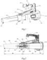
- Fig. 1 shows a blower according to an embodiment of the present invention
- the blower is an axial-flow blower, and comprises a blower body 100 and a blow pipe 300 mounted on the blower body 100.
- a fan, and a drive unit driving the fan to rotate, are accommodated in the blower body 100.
- a user can remove the blow pipe 300 from the blower body 100 to reduce storage space.
- the blower defines an airflow path from an air inlet to an air outlet. The air inlet is formed on the blower body 100, while the air outlet is formed on the blow pipe 300.
- a straight line on which a rotation shaft of the fan in the blower lies is defined as a longitudinal axis, a side facing toward the air outlet is called a far side, and a side facing toward the air inlet is called a near side.
- the blow pipe 300 is connected to the blower body 100 via a snap-fit connector 330 located at the near side thereof. It should be understood that other forms of dismantlable connection are also feasible, and are included in the scope of the present invention.
- the blower body 100 comprises a body housing 200 and a casing that defines the airflow path.
- the body housing 200 may consist of two housing halves, to facilitate dismantling.
- the casing comprises an air-intake-side casing 400 and an air-output-side casing 500.
- a guard 210 is attached to a near-side part of the body housing 200, and defines the air inlet of the blower.
- a protective grille is formed on the guard 210 to prevent foreign objects from entering the body housing 200.
- the grille pattern is designed to help organize disordered external air into a smooth intake airflow.
- the blower body 100 further comprises a handle 220.
- the handle 220 has a gripping part 221 for a user to grip, and a connecting part 222 that connects the gripping part 221 to the body housing 200.
- a control button 223 is provided on the gripping part 221, to enable the user to operate the blower with a single hand.
- the connecting part 222 is pivotably connected to the body housing 220, to allow the user to adjust the orientation of the handle 220 relative to the body housing 200.
- the blower body 100 further comprises a battery pack installation mechanism 230, for attaching a removable battery pack (not shown in the figures).
- a battery pack installation mechanism 230 for attaching a removable battery pack (not shown in the figures).
- the battery pack installation mechanism 230 is arranged on the connecting part 222 of the handle 220. This arrangement has the advantage that the battery pack is installed directly on the handle 220, closer to the gripping part 221, so the user is able to maintain the orientation of the blower steadily while holding the blower in the hand to perform a job.
- the battery pack installation mechanism may be arranged at a lower part or a side of the body housing 200.
- Fig. 2 shows a cross section of the blower. External air enters the blower body 100 through the guard 210 under the driving action of the fan 600, flows sequentially through the air-intake-side casing 400, the air-output-side casing 500 and the blow pipe 300, finally exiting through the air outlet at a far end of the blow pipe 300. Viewed from one side, outer walls 310, 320 of the blow pipe 300 form an angle with respect to the longitudinal axis L. The angle is preferably less than 5 degrees, more preferably less than 2 degrees.
- the upper-side outer wall 310 of the blow pipe 300 extends a greater distance along the longitudinal axis L than the lower-side outer wall 320.
- a bottom support 340 is provided at a near-side part of the blow pipe 300, allowing the blower to be placed stably on the ground, and preventing wear to a blow pipe outer surface.
- a protrusion 350 is provided at the bottom of a far-end edge of the blow pipe; when the blow pipe is placed on its own, the bottom support 340 and the protrusion 350 can support the blow pipe 300 stably.
- a control unit for controlling fan rotation is generally arranged outside the airflow path, e.g. in the handle 220 or in a connection part S of the handle 220 and the body housing 200.
- the control unit must be provided with a means of cooling, because electronic components in the control unit generate heat when the blower is operating.
- the means of cooling includes providing a metal heat sink on the control unit, and at the same time forming a ventilation port on the body housing close to the control unit.
- the metal heat sink is heavy and will be a burden on the user. In environments where there is no wind or only gentle wind, the amount of air entering the housing through the ventilation port is limited, and is unable to rapidly carry away heat from the metal heat sink.
- a control circuit board 800 used as the control unit is arranged in the airflow path, and the control unit is cooled by an airflow generated by the fan 600 when rotating.
- the control circuit board 800 may be arranged close to a motor 700 of the drive unit, e.g. at an end of the motor 700.
- the control circuit board 800 in the airflow direction, is located downstream of the motor 700, while the fan 600 is located upstream of the motor 700. In other embodiments, the control circuit board 800 is located upstream of the motor 700, while the fan 600 is located downstream of the motor 700.
- the control circuit board 800 is located substantially in a middle section of the overall length of the blower.
- the ratio d1/d2 of a distance d1 between the control circuit board 800 and the air inlet defined by the guard 210, and a distance d2 between the control circuit board 800 and the air outlet defined by the blow pipe 300 is 0.7 - 1.3.
- Fig. 3 shows the air-intake-side casing 400 and the air-output-side casing 500 which define the airflow path in the blower body 100.
- a near end of the air-intake-side casing 400 is connected to the guard 210, while a far end of the air-output-side casing 500 is connected to the blow pipe 300.
- a near-side part 410 of the air-intake-side casing 400 is designed to gradually open outward in the near-side direction.
- the air-intake-side casing 40 is substantially cylindrical, and comprises at least one positioning member 420.
- the positioning member 420 may be formed on an outer wall of the air-intake-side casing 400; the positioning member 420 engages with a positioning member formed at a corresponding position on the body housing 200, to ensure that the air-intake-side casing 400 is installed at a predetermined position of the blower body 100.
- a positioning member 511 is also provided on an outer wall of the air-output-side casing 500, and likewise engages with a positioning member formed at a corresponding position on the body housing.
- At least a part of the air-output-side casing 500 and the air-intake-side casing 400 is exposed to the outside environment.
- the air-intake-side casing 400 and the air-output-side casing 500 are located inside the body housing 200, with neither being exposed to the outside environment.
- An elastic positioning member may be provided on the outer wall of the air-intake-side casing 400 and/or the air-output-side casing 500.
- the thickness of the elastic positioning member is slightly greater than a distance between a casing outer wall and a body housing inner wall, such that the elastic positioning member is squeezed between the casing outer wall and the body housing inner wall, thereby positioning the casing in the body housing in a centered fashion, to resist vibration and reduce noise.
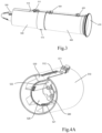
- Figs. 4A and 4B show the structure of the air-output-side casing 500.
- the air-output-side casing 500 comprises an outer ring 510 formed of an outer wall, and an inner ring 520 located inside the outer ring 510.
- the outer ring 510 is connected to the inner ring 520 via multiple static vanes 530.
- the multiple static vanes 530 are spaced apart circumferentially, and used to guide airflow.
- the inner ring 520 defines a motor casing, with a motor assembly accommodated therein.
- a far end of the inner ring 520 is open, while a near end thereof has a motor mounting frame 540.
- Fig. 4B shows that the motor mounting frame 540 has a central hole 541, for a motor shaft to pass through.
- At least one fastener hole 542 is formed in the motor mounting frame 540; a fastener (e.g. a screw) can pass through the fastener hole 542 to fix the motor to the motor mounting frame 540.
- a fastener e.g. a screw
- an opening 543 is formed at the periphery of the motor mounting frame 540, and connects the interior of the motor casing with the outside, allowing air to enter or exit the motor casing.
- a protruding piece 513 is also provided on the outer wall of the air-output-side casing 500; a hole in the protruding piece 513 is used to receive a fastener which fixes the air-intake-side casing 400 to the air-output-side casing 500.
- the air-output-side casing 500 comprises a tapered flow-guiding body 550 which narrows gradually toward the far side.
- Fig. 5 shows the tapered flow-guiding body, which is hollow and comprises at least one connector 551 extending toward a near end.
- the connector 551 in this embodiment is a hook-like member, and is mated with a connector 521 formed at the near side of the inner ring 520, to achieve a fixed connection between the tapered flow-guiding body 550 and the inner ring 520.
- the tapered flow-guiding body 550 and the inner ring 520 may be connected in any way, or the tapered flow-guiding body 550 and the inner ring 520 are integrally formed.
- At least one opening 552 is formed in an outer surface of the tapered flow-guiding body 550, and connects the interior of the tapered flow-guiding body 550 to the outside, allowing air to enter or exit the tapered flow-guiding body.
- the tapered flow-guiding body 550 further comprises a wing part 560.
- the wing part 560 has an inner wall 561, an outer wall 562 located at a radially outer side of the inner wall 561, and a connecting piece 563 which connects the inner wall 561 to the outer wall 562.
- the inner ring 520 and outer ring 510 of the air-output-side casing 500 shown in Fig. 4A are not completely closed circumferentially, having an inner ring slot 522 and an outer ring slot 512 respectively.
- the inner wall 561 and outer wall 562 of the wing part 560 enter the inner ring slot 522 and outer ring slot 512 respectively, and the connecting piece 560 is used as a static vane between the outer ring 510 and the inner ring 520.
- Fig. 6 shows a cross section of the air-output-side casing 500, with the motor assembly and fan 600 accommodated therein.
- the motor assembly comprises the motor 700, and the control circuit board 800 for controlling the operation of the motor.
- the motor assembly is positioned in the motor casing defined by the inner ring 520.
- the fan 600 is located outside the motor casing and at the near side of the motor 700; and the fan 600 is mounted on an output shaft 750 of the motor 700.
- at least a part of the tapered flow-guiding body 550 protrudes beyond the outer ring 510, with the opening 552 being formed in part of the protruding part.
- a near-end edge of the tapered flow-guiding body 550 is aligned with a far-end edge of the inner ring 520; when connected together, the tapered flow-guiding body 550 and the inner ring 520 define a bullet-shaped internal space. It must be explained that although the control circuit board 800 shown in Fig. 6 is located in the inner ring 520, the control circuit board 800 may also be arranged at other positions in the internal space.
- Fig. 7 shows the fan and the motor assembly.
- the fan 600 comprises a hub 610, and blades 620 extending radially outward from the hub 610.
- the hub 610 is substantially aligned with the inner ring 520 of the air-output-side casing 500 in the axial direction.
- a gap between an extremity of the blade 620 and an inner wall 515 (shown in Fig. 4B ) of the outer ring 510 of the air-output-side casing 500 is preferably 0.5 - 2.5 mm, and more preferably 0.8 - 1.5 mm. Too small a gap might result in the blade scraping the casing inner wall; too large a gap would increase noise, and reduce blowing efficiency.
- the control circuit board 800 in the motor assembly is located at the near side of the motor 700.
- the motor 700 is an internal rotor motor; a housing of the motor 700 comprises a first housing part 720 and a second housing part 730, and the control circuit board 800 is connected to the second housing part 730 in a fixed manner.
- Figs. 8A and 8B show the structure of the second housing part 730.
- the second housing part 730 comprises a bottom wall 731 covering one end of the motor 700, and a sidewall 732 surrounding stator laminations 710.
- the second housing part 730 further comprises two sets of fastener holes.
- a first set of fastener holes 735 is formed in the sidewall 732, being aligned with fastener holes formed in a sidewall of the first housing part 720, and configured to receive fasteners 740 (shown in Fig. 7 ) for fixing the first and second housing parts 720, 730.
- a second set of fastener holes 734 is formed in the bottom wall 731, being configured to receive fasteners for fixing the control circuit board 800.
- a a cylindrical part 737 is also formed on the bottom wall 731, and configured to accommodate a motor bearing.
- a central through-hole 733 in the bottom wall 731 allows the motor shaft to pass through.
- the first housing part 720 and second housing part 730 do not completely enclose the motor 700; a portion of the stator laminations 710 are not covered by the first housing part 720 and second housing part 730.
- the non-fully-enclosing motor housing makes it easy for air to come into contact with heat-generating components in the motor, thereby increasing the cooling efficiency.
- at least one opening 736 is formed in the sidewall 732 of the second housing part 730.
- the first housing part 720 may have substantially the same structure as the second housing part 730, including two sets of fastener holes formed on a sidewall and a bottom wall.
- the fastener holes in the bottom wall of the first housing part 720 are aligned with the fastener holes 542 (shown in Fig. 4B ) formed in the motor mounting frame 540 of the air-output-side casing 500, and configured to receive fasteners for fixing the motor.
- Fig. 9 shows the control circuit board 800, on which are arranged various electronic components 801, 802 for controlling motor operation.
- the shape of the control circuit board 800 corresponds to the cross-sectional shape of the motor housing.
- the ratio of the cross-sectional area of the control circuit board 800 to the cross-sectional area of the motor housing is 0.7 - 1.5, more preferably 0.9 - 1.1.
- Fastener holes 820 are formed in the control circuit board 800, being aligned with the second set of fastener holes 734 formed in the bottom wall 731 of the second housing part 730.
- At least one through-hole is also formed in the control circuit board, e.g. a through-hole 810 located in the center and a through-hole 830 close to an edge, or a notch is formed in an edge of the control circuit board.
- These through-holes or notches allow air to pass through the control circuit board 800 and carry away heat generated by the electronic components during operation.
- the through-hole 810 located in the center may also accommodate the motor shaft.
- this shows flow paths of air when the blower is operating.
- An airflow passes through an annular region between the inner ring 520 and the outer ring 510 under the action of the fan, then exits the air-output-side casing 500 under the guiding action of the tapered flow-guiding body 550 and enters the blow pipe 300.
- the inner wall 561 of the wing part 560 of the tapered flow-guiding body 550 does not completely occupy the inner ring slot 522 in the inner ring 520 of the air-output-side casing 500.
- the part of the inner ring slot 522 which is not occupied by the inner wall 561 forms an inner ring hole 524, which connects the annular region with the inner ring 520.
- the outer wall 562 of the wing part 560 does not completely occupy the outer ring slot 512 in the outer ring 510.
- the part of the outer ring slot 512 which is not occupied by the outer wall 562 forms an outer ring hole 514, which connects the air-output-side casing 500 with the body housing 200.
- the outer ring hole 514 and inner ring hole 524 are aligned in a vertical direction. An electric wire connected to the control button on the handle 220 can pass through the outer ring hole 514 and inner ring hole 524 to reach the control circuit board 800.
- the air which exits the air-output-side casing 500 through the annular region is referred to as a main air flow
- the air which enters the motor casing through the inner ring hole 524 is referred to as a cooling air flow, to make it easier to distinguish between the two.
- the control circuit board 800 is positioned close to the motor 700, preferably downstream of the inner ring hole 524, so that the cooling air flow can also cool the control circuit board 800. Since the control circuit board 800 is located in the inner ring 520 of the air-output-side casing 500, it will not affect the main air flow.
- the control circuit board 800 is arranged substantially transversely to the longitudinal axis, i.e. transversely to the flow direction of the cooling air flow. This manner of arrangement increases the area of contact between the control circuit board 800 and the cooling air flow. Furthermore, due to the blocking action of the control circuit board 800, the cooling air flow is not able to exit the inner ring 520 rapidly, which increases the time of contact between the cooling air flow and the control circuit board 800.
- the ratio of the cross-sectional area of the control circuit board 800 to the area enclosed by the inner ring 520 is preferably 0.5 - 0.9, more preferably 0.7 - 0.9.
- the ratio of the cross-sectional area of the control circuit board 800 to the area enclosed by the outer ring 510 is 0.3 - 0.7, more preferably 0.4 - 0.6.
- Fig. 10 is a view of an end face of the tapered flow-guiding body 550. Viewed in a direction from the near side to the far side, three openings 552 in the tapered flow-guiding body 550 are spaced apart circumferentially. Each opening 552 is enclosed by two arcs 553, 554 and two sides. The two arcs 553, 554 are arc sections on two circles of different radii centered at the center of an extremity 570 of the tapered flow-guiding body 550. The openings 552 enable the cooling air flow to rapidly enter the blow pipe 300 through the tapered flow-guiding body 550, thereby carrying away heat generated by the motor 700 and the control circuit board 800.
- the number, shape and manner of arrangement of the openings may be varied; for example, round or annular openings may be chosen.
- an opening may also be formed at the extremity 570 of the tapered flow-guiding body.
- the shape and arrangement of the openings should be designed in such a way that interference to the main air flow from the cooling air flow is avoided as much as possible.
- the manner of arrangement of the openings shown in Fig. 10 is able to achieve this result.
- the motor driving rotation of the fan is a brushless DC motor controlled in a sensorless fashion
- a position sensor e.g. a Hall sensor
- the working airflow generated by fan rotation can be used to effectively cool the control circuit board, thus there is no need for the control circuit board to be provided with a heat sink.
- This can reduce the weight of the blower, reducing the feeling of fatigue experienced by the user when working with the blower held in the hand for a long period of time.
- the control circuit board is located in the air channel, space for accommodating the control circuit board does not need to be left in the blower housing. This helps to optimize the housing design, reducing the overall size of the blower.
Landscapes
- Engineering & Computer Science (AREA)
- Mechanical Engineering (AREA)
- General Engineering & Computer Science (AREA)
- Physics & Mathematics (AREA)
- Thermal Sciences (AREA)
- Microelectronics & Electronic Packaging (AREA)
- Life Sciences & Earth Sciences (AREA)
- Environmental Sciences (AREA)
- Structures Of Non-Positive Displacement Pumps (AREA)
Claims (13)
- Gebläse, umfassend:einen Gebläsekörper (100), der einen Lüfter (600) und eine Antriebseinheit darin untergebracht aufweist, wobei eine Drehwelle des Lüfters eine Längsachse definiert und der Gebläsekörper einen Lufteinlass definiert;ein Gebläserohr (300), das an dem Gebläsekörper (100) angebracht ist und sich entlang der Längsachse erstreckt, wobei das Gebläserohr (300) einen Luftauslass definiert;eine Steuereinheit zum Steuern eines Betriebs der Antriebseinheit, wobei die Antriebseinheit einen Motor (700) umfasst und die Steuereinheit eine Steuerplatine (800) umfasst, die sich an einem Ende des Motors (700) befindet; vorzugsweise in einer Luftströmungsrichtung, wobei sich eines der Steuerplatine (800) und des Lüfters (600) stromabwärts des Motors (700) befindet, während sich das andere stromaufwärts des Motors (700) befindet;wobei das Gebläse einen Luftströmungspfad definiert, der sich von dem Lufteinlass zu dem Luftauslass erstreckt, wobei sich die Steuereinheit mindestens teilweise in dem Luftströmungspfad derart befindet, dass, wenn das Gebläse in Betrieb ist, mindestens ein Anteil einer Luftströmung, die in den Lufteinlass eintritt, die Steuereinheit kühlt und dann durch den Luftauslass abgeführt wird;wobei der Gebläsekörper ein Gehäuse umfasst, in dem sich der Lüfter (600), der Motor (700) und die Steuerplatine (800) befinden, und wobei das Gehäuse einen hohlen konischen Strömungsleitkörper (550) umfasst, wobei der konische Strömungsleitkörper (550) eine Öffnung (552) aufweist, die in einer Oberfläche und/oder einem Ende des konischen Strömungsleitkörpers (550) ausgebildet ist;wobei das Gehäuse einen Außenring (510) und einen Innenring (520) umfasst, wobei der konische Strömungsleitkörper (550) mit dem Innenring (520) verbunden ist und die Steuerplatine (800) in einem Raum angeordnet ist, der durch den konischen Strömungsleitkörper (550) und den Innenring (520) definiert ist;dadurch gekennzeichnet, dass der konische Strömungsleitkörper (550) ferner ein Flügelteil (560) umfasst, wobei das Flügelteil (560) eine Innenwand (561), eine Außenwand (562), die sich an einer radial äußeren Seite der Innenwand (561) befindet, und ein Verbindungsteil (563) aufweist, das die Innenwand (561) mit der Außenwand (562) verbindet; und ein Innenringschlitz (522) und ein Außenringschlitz (512), die mit der Innenwand (561) und der Außenwand (562) zusammenpassen, in dem Innenring (510) beziehungsweise dem Außenring (520) des Gehäuses ausgebildet sind.
- Gebläse nach Anspruch 1, dadurch gekennzeichnet, dass die Steuereinheit nahe der Antriebseinheit angeordnet ist und vorzugsweise im Wesentlichen quer zu der Längsachse ist.
- Gebläse nach Anspruch 1, dadurch gekennzeichnet, dass sich in einer Luftströmungsrichtung eines der Steuerplatine (800) und des Lüfters (600) stromabwärts des Motors (700) befindet, während sich das andere stromaufwärts des Motors (700) befindet.
- Gebläse nach Anspruch 1, dadurch gekennzeichnet, dass mehrere Öffnungen, die in Umfangsrichtung beabstandet sind, in der Oberfläche des konischen Strömungsleitkörpers (550) ausgebildet sind, wobei jede der Öffnungen durch zwei Bögen und zwei Seiten umschlossen ist, die zwei Bögen Bogenabschnitte auf zwei Kreisen mit unterschiedlichen Radien sind, die in dem Zentrum des Endes des konischen Strömungsleitkörpers (550) zentriert sind.
- Gebläse nach Anspruch 1, dadurch gekennzeichnet, dass der Gebläsekörper einen Schutz umfasst, der den Lufteinlass definiert, und in der Richtung der Längsachse das Verhältnis eines Abstands zwischen der Steuerplatine (800) und dem Lufteinlass und eines Abstands zwischen der Steuerplatine (800) und dem Luftauslass 0,7-1,3 beträgt.
- Gebläse nach Anspruch 1, dadurch gekennzeichnet, dass der Motor (700) ein bürstenloser Gleichstrommotor ist, der auf eine sensorlose Weise gesteuert wird, und kein Kühlkörper auf der Steuerplatine (800) vorhanden ist.
- Gebläse nach Anspruch 1, dadurch gekennzeichnet, dass mindestens ein Teil des konischen Strömungsleitkörpers (550) über den Außenring (520) hinausragt, wobei die Öffnung (552) in dem mindestens einen Teil ausgebildet ist.
- Gebläse nach Anspruch 1, dadurch gekennzeichnet, dass ein Teil des Innenringschlitzes (522), der nicht durch die Innenwand (561) eingenommen ist, ein Innenringloch ausbildet, wobei sich die Steuerplatine (800) stromabwärts des Innenringlochs befindet.
- Gebläse nach einem der Ansprüche 1 bis 8,
dadurch gekennzeichnet, dass ein Querschnitt der Steuerplatine (800) einem Querschnitt des Motors (700) entspricht, und vorzugsweise das Verhältnis einer Querschnittsfläche der Steuerplatine (800) zu einer Querschnittsfläche eines Motorgehäuses 0,7 - 1,5, mehr bevorzugt 0,9 - 1,1 beträgt. - Gebläse nach einem der Ansprüche 1 bis 8,
dadurch gekennzeichnet, dass das Verhältnis einer Querschnittsfläche der Steuerplatine (800) zu einer Fläche, die durch den Innenring (520) umschlossen ist, 0,5-0,9, vorzugsweise 0,7 - 0,9 beträgt, und das Verhältnis der Querschnittsfläche der Steuerplatine (800) zu einer Fläche, die durch den Außenring (510) umschlossen ist, 0,3 - 0,7, vorzugsweise 0,4 - 0,6 beträgt. - Gebläse nach einem der Ansprüche 1 - 82 -10,
dadurch gekennzeichnet, dass die Steuerplatine (800) mittels eines Befestigungselements mit einem Motorgehäuse verbunden ist, und mindestens ein Teil des Motors (700) nicht durch das Motorgehäuse abgedeckt ist. - Gebläse nach Anspruch 11, dadurch gekennzeichnet, dass das Motorgehäuse einen ersten Gehäuseteil, der sich an einem Ende des Motors (700) befindet, und einen zweiten Gehäuseteil umfasst, der sich an dem anderen Ende des Motors (700) befindet, wobei die Steuerplatine (800) an dem zweiten Gehäuseteil fixiert ist und der zweite Gehäuseteil eine Bodenwand und eine Seitenwand umfasst; ein erster Satz von Befestigungslöchern in der Seitenwand ausgebildet ist, ein zweiter Satz von Befestigungslöchern in der Bodenwand ausgebildet ist und mindestens eine Öffnung, die in das Innere des Motors (700) führt, in der Seitenwand ausgebildet ist.
- Gebläse nach einem der Ansprüche 1 bis 8,
dadurch gekennzeichnet, dass die Steuerplatine (800) mindestens ein Durchgangsloch und/oder eine Kerbe aufweist, die einer Luftströmung erlaubt, durch die Steuerplatine (800) zu verlaufen.
Applications Claiming Priority (1)
| Application Number | Priority Date | Filing Date | Title |
|---|---|---|---|
| CN202110162588.0A CN114876827A (zh) | 2021-02-05 | 2021-02-05 | 吹风机 |
Publications (3)
| Publication Number | Publication Date |
|---|---|
| EP4039083A1 EP4039083A1 (de) | 2022-08-10 |
| EP4039083C0 EP4039083C0 (de) | 2024-10-23 |
| EP4039083B1 true EP4039083B1 (de) | 2024-10-23 |
Family
ID=79730279
Family Applications (1)
| Application Number | Title | Priority Date | Filing Date |
|---|---|---|---|
| EP22151967.1A Active EP4039083B1 (de) | 2021-02-05 | 2022-01-18 | Blasgerät |
Country Status (5)
| Country | Link |
|---|---|
| US (1) | US11873824B2 (de) |
| EP (1) | EP4039083B1 (de) |
| CN (1) | CN114876827A (de) |
| AU (1) | AU2022200620A1 (de) |
| CA (1) | CA3147971A1 (de) |
Families Citing this family (11)
| Publication number | Priority date | Publication date | Assignee | Title |
|---|---|---|---|---|
| JP7768823B2 (ja) * | 2022-04-20 | 2025-11-12 | 株式会社マキタ | ブロワ |
| USD1046337S1 (en) * | 2022-09-01 | 2024-10-08 | Zhejiang Dadao Electric Appliance Co., Ltd. | Blower |
| CN115467847A (zh) * | 2022-09-26 | 2022-12-13 | 全小华 | 一种改进型电吹风结构 |
| CN121263572A (zh) * | 2023-05-23 | 2026-01-02 | 胡斯华纳有限公司 | 吹叶机 |
| USD1011661S1 (en) * | 2023-06-15 | 2024-01-16 | Ningbo Winbay Technology Co., Ltd. | Leaf blower |
| EP4520166A3 (de) * | 2023-09-07 | 2025-05-21 | Greenworks (Jiangsu) Co., Ltd. | Gebläse |
| USD1071407S1 (en) * | 2024-03-11 | 2025-04-15 | Shanghai Hoto Technology Co., Ltd. | Leaf blower |
| US12431763B1 (en) * | 2024-05-09 | 2025-09-30 | Whisper Aero Inc. | Conductive aerodynamic stator |
| CN119467396B (zh) * | 2024-12-03 | 2025-10-31 | 崇左中电环保有限公司 | 一种高效真空泵机组 |
| USD1081044S1 (en) * | 2025-01-06 | 2025-06-24 | Zhijun Yang | Leaf blower |
| CN120273293B (zh) * | 2025-06-12 | 2026-04-28 | 山西正工电气设备有限公司 | 一种道岔区融雪除冰装置 |
Family Cites Families (79)
| Publication number | Priority date | Publication date | Assignee | Title |
|---|---|---|---|---|
| US4659951A (en) | 1986-02-14 | 1987-04-21 | General Motors Corporation | Brushless blower motor with load proportional cooling for control circuitry |
| US6006400A (en) | 1996-02-26 | 1999-12-28 | Presenza; Tom | Electric backpack blower |
| US6105206A (en) * | 1999-04-13 | 2000-08-22 | Department Of Water And Power City Of Los Angeles | Portable electrically powered blower apparatus |
| US6488475B2 (en) * | 2000-03-30 | 2002-12-03 | Matsushita Electric Industrial Co., Ltd. | Electric blower and electric cleaner with an air cooled power device situated between the impeller and motor |
| TW200740085A (en) | 2006-04-13 | 2007-10-16 | Sunonwealth Electr Mach Ind Co | Heat dissipation structure for base of motor |
| JP4992287B2 (ja) | 2006-04-28 | 2012-08-08 | 日本電産株式会社 | モータ |
| CN101071964B (zh) | 2006-05-10 | 2010-07-14 | 建准电机工业股份有限公司 | 一种马达基座 |
| TWI337437B (en) | 2006-12-22 | 2011-02-11 | Delta Electronics Inc | Fan, motor and fixture thereof |
| WO2008104274A2 (de) | 2007-02-28 | 2008-09-04 | Sew-Eurodrive Gmbh & Co. Kg | Elektromotor |
| JP5013314B2 (ja) | 2007-06-18 | 2012-08-29 | 日立工機株式会社 | 電動工具 |
| DE102008033959B4 (de) * | 2008-07-21 | 2010-07-15 | Siemens Aktiengesellschaft | Elektrische Maschine mit Radialtrennblechen zur Kühlluftführung |
| DE102008044390A1 (de) | 2008-12-05 | 2010-06-10 | Robert Bosch Gmbh | Elektrowerkzeug mit einem Gleichstrommotor und Leistungselektronik |
| WO2010129734A2 (en) * | 2009-05-06 | 2010-11-11 | Munters Corporation | Fan for use in agriculture |
| JP5472683B2 (ja) | 2009-05-11 | 2014-04-16 | 日立工機株式会社 | 電動工具 |
| DE102010025586B4 (de) | 2009-07-01 | 2021-04-15 | Johnson Electric International AG | Elektrowerkzeug |
| TWI426681B (zh) | 2010-09-21 | 2014-02-11 | Delta Electronics Inc | 風扇及其馬達 |
| DE102011121062A1 (de) | 2011-12-14 | 2013-06-20 | Diehl Ako Stiftung & Co. Kg | Antriebsvorrichtung, insbesondere für ein elektronisches Haushaltsgerät |
| JP2013138576A (ja) | 2011-12-28 | 2013-07-11 | Nippon Densan Corp | ファンモータ |
| JP2013187922A (ja) | 2012-03-06 | 2013-09-19 | Nippon Densan Corp | ファンモータ |
| JP5942580B2 (ja) | 2012-05-15 | 2016-06-29 | マックス株式会社 | 電動工具 |
| JP5983929B2 (ja) * | 2012-08-20 | 2016-09-06 | 日立工機株式会社 | 携帯用ブロワ |
| CN202985527U (zh) | 2012-11-07 | 2013-06-12 | 应时立 | 直驱式电动工具 |
| CN202929231U (zh) | 2012-11-19 | 2013-05-08 | 上海大学 | 一种滤光片自动排片机 |
| CN102969861A (zh) | 2012-12-03 | 2013-03-13 | 常州格力博有限公司 | 无刷电机 |
| CN202926689U (zh) | 2012-12-12 | 2013-05-08 | 瑞安市日正汽车部件有限公司 | 一种智能型鼓风机 |
| CN203313001U (zh) | 2013-05-23 | 2013-11-27 | 冼锡彬 | 电风扇电机 |
| KR102124513B1 (ko) | 2014-01-29 | 2020-06-18 | 삼성전자주식회사 | 모터 |
| CN106133329B (zh) * | 2014-03-17 | 2020-01-17 | 胡斯华纳有限公司 | 动力设备冷却系统 |
| EP2961038B1 (de) | 2014-06-05 | 2019-12-11 | Samsung Electronics Co., Ltd. | Staubsauger mit motoranordnung |
| EP3158202A4 (de) | 2014-06-19 | 2018-03-07 | Gentherm Automotive Systems (China) Ltd. | Luftumwälzerschaltung und nachgiebiges glied |
| DE102014009146A1 (de) | 2014-06-20 | 2015-12-24 | Ziehl-Abegg Se | Elektromotor mit einem Rotor, einem Stator und einem Elektronikgehäuse sowie Lüfterrad für einen Elektromotor |
| JP2016112523A (ja) * | 2014-12-16 | 2016-06-23 | 株式会社マキタ | 送風作業機 |
| CN105822595B (zh) | 2015-01-09 | 2019-11-08 | 日本电产株式会社 | 电动送风机及包含该电动送风机的电动扫除机 |
| US10348158B2 (en) | 2015-02-04 | 2019-07-09 | Makita Corporation | Power tool |
| WO2016158154A1 (ja) | 2015-03-30 | 2016-10-06 | 株式会社デンソー | 送風装置 |
| CN204669169U (zh) | 2015-06-26 | 2015-09-23 | 卧龙电气集团股份有限公司 | 一种一体式风机专用变频电机用pcb板安装结构 |
| US11035381B2 (en) | 2015-09-16 | 2021-06-15 | Regal Beloit America, Inc. | Blower, electric machine and associated method |
| DE102015219150A1 (de) | 2015-10-02 | 2017-04-06 | Ziehl-Abegg Se | Motor für Lüfter bzw. Ventilatoren, Pumpen oder Kompressoren, Verfahren zum Betrieb eines solchen Motors und Ventilatorsystem mit einem oder mehreren Motor(en)/Ventilator(en) |
| US10786894B2 (en) | 2015-10-14 | 2020-09-29 | Black & Decker Inc. | Brushless motor system for power tools |
| CN106685124B (zh) | 2015-11-06 | 2019-05-03 | 中达电子零组件(吴江)有限公司 | 马达的定子组件及其绕线结构 |
| EP3377272B1 (de) | 2015-11-20 | 2020-11-18 | TTI (Macao Commercial Offshore) Limited | Elektrowerkzeuge mit leiterplatten |
| KR102038240B1 (ko) * | 2016-01-13 | 2019-10-29 | 미츠비시 히타치 파워 시스템즈 가부시키가이샤 | 날개 인발 장치 및 방법 |
| CN205545053U (zh) | 2016-04-22 | 2016-08-31 | 江苏新安电器有限公司 | 一种集成变频电机控制器 |
| CN107725413B (zh) | 2016-08-12 | 2021-07-13 | 德昌电机(深圳)有限公司 | 风机 |
| US10840771B2 (en) | 2016-09-28 | 2020-11-17 | Mitsubishi Electric Corporation | Motor, blower, air conditioner, and method of producing motor |
| KR101982115B1 (ko) | 2016-12-23 | 2019-05-24 | 엘지전자 주식회사 | 청소기의 노즐 |
| JP2018117505A (ja) | 2017-01-20 | 2018-07-26 | 日本電産株式会社 | モータ及びそれを備えた送風装置 |
| CN206442252U (zh) | 2017-02-10 | 2017-08-25 | 中国第一汽车股份有限公司 | 一种高集成电机控制器总成 |
| EP3580832A4 (de) | 2017-02-13 | 2021-03-03 | Milwaukee Electric Tool Corporation | Bürstenloser gleichstrommotor für elektrowerkzeuge |
| CN206815249U (zh) | 2017-03-16 | 2017-12-29 | 苏州宝时得电动工具有限公司 | 动力工具 |
| US20180263446A1 (en) | 2017-03-17 | 2018-09-20 | Nidec Corporation | Blower and vacuum cleaner |
| CN108696057B (zh) | 2017-04-12 | 2021-06-25 | 德昌电机(深圳)有限公司 | 电机及具有该电机的用电设备 |
| CN108964363A (zh) | 2017-05-17 | 2018-12-07 | 德昌电机(深圳)有限公司 | 一种电机、控制电路板及应用该电机的引擎冷却模组 |
| CN110754015B (zh) * | 2017-06-09 | 2022-11-04 | 胡斯华纳有限公司 | 具有改进的电池冷却的鼓风机 |
| JP6901948B2 (ja) | 2017-09-29 | 2021-07-14 | 株式会社マキタ | 電動作業機 |
| JPWO2019064897A1 (ja) | 2017-09-29 | 2020-10-15 | 日本電産株式会社 | モータ |
| JP2019068687A (ja) | 2017-10-04 | 2019-04-25 | 日本電産株式会社 | 送風装置、及び、掃除機 |
| US10348153B2 (en) | 2017-10-24 | 2019-07-09 | Denso International America, Inc. | HVAC blower motor assembly |
| US20190159640A1 (en) | 2017-11-24 | 2019-05-30 | Nidec Corporation | Blower and cleaner |
| JP2019103205A (ja) | 2017-11-30 | 2019-06-24 | 日本電産株式会社 | 回路基板、モータ、及びファンモータ |
| JP2019100314A (ja) | 2017-12-07 | 2019-06-24 | 日本電産株式会社 | 送風装置 |
| JP2019129543A (ja) | 2018-01-19 | 2019-08-01 | 日本電産株式会社 | モータ、送風装置及び掃除機 |
| JP2019180195A (ja) | 2018-03-30 | 2019-10-17 | 日本電産サーボ株式会社 | モータ、遠心ファン |
| JP2019180196A (ja) | 2018-03-30 | 2019-10-17 | 日本電産サーボ株式会社 | モータ |
| CN208930176U (zh) | 2018-05-02 | 2019-06-04 | 大成电机股份有限公司 | 具有整合式电路板的电动工具 |
| TWI706623B (zh) | 2018-06-07 | 2020-10-01 | 車王電子股份有限公司 | 無刷馬達總成 |
| CN110620476B (zh) | 2018-06-20 | 2022-06-21 | 车王电子股份有限公司 | 无刷马达总成 |
| TWI678867B (zh) | 2018-07-09 | 2019-12-01 | 群光電能科技股份有限公司 | 變頻器整合馬達 |
| JP7136902B2 (ja) | 2018-09-03 | 2022-09-13 | 本田技研工業株式会社 | 電動パワーユニット、および作業機 |
| CN209244874U (zh) | 2018-09-28 | 2019-08-13 | 日本电产株式会社 | 送风机 |
| JP7135801B2 (ja) | 2018-12-03 | 2022-09-13 | 日本電産株式会社 | モータおよびファンモータ |
| CN115085439A (zh) | 2019-01-11 | 2022-09-20 | 台达电子工业股份有限公司 | 马达结构 |
| CN113395925B (zh) * | 2019-03-15 | 2022-04-19 | 工机控股株式会社 | 送风机 |
| US20220183241A1 (en) * | 2019-03-27 | 2022-06-16 | Positec Power Tools (Suzhou) Co., Ltd | Garden blower |
| WO2020208790A1 (ja) | 2019-04-11 | 2020-10-15 | 三菱電機株式会社 | 電動送風機、電気掃除機およびハンドドライヤー |
| CN110425161A (zh) | 2019-07-24 | 2019-11-08 | 河北驰马拓电机科技有限公司 | 一种低风阻的高流速轴流风机及送风设备 |
| CN211449186U (zh) | 2019-11-08 | 2020-09-08 | 日本电产株式会社 | 送风装置和电气设备 |
| CN211474470U (zh) | 2019-11-08 | 2020-09-11 | 日本电产株式会社 | 送风装置和电气设备 |
| CN211648591U (zh) | 2019-12-11 | 2020-10-09 | 鼎朋企业股份有限公司 | 吸尘装置的抽风马达 |
-
2021
- 2021-02-05 CN CN202110162588.0A patent/CN114876827A/zh active Pending
-
2022
- 2022-01-18 EP EP22151967.1A patent/EP4039083B1/de active Active
- 2022-01-31 AU AU2022200620A patent/AU2022200620A1/en active Pending
- 2022-02-03 US US17/592,224 patent/US11873824B2/en active Active
- 2022-02-03 CA CA3147971A patent/CA3147971A1/en active Pending
Also Published As
| Publication number | Publication date |
|---|---|
| US11873824B2 (en) | 2024-01-16 |
| EP4039083C0 (de) | 2024-10-23 |
| EP4039083A1 (de) | 2022-08-10 |
| CN114876827A (zh) | 2022-08-09 |
| AU2022200620A1 (en) | 2022-08-25 |
| US20220252076A1 (en) | 2022-08-11 |
| CA3147971A1 (en) | 2022-08-05 |
Similar Documents
| Publication | Publication Date | Title |
|---|---|---|
| EP4039083B1 (de) | Blasgerät | |
| US10774487B2 (en) | Handheld blower having engine cooling flow | |
| AU2021101003A4 (en) | Blower | |
| JP6127840B2 (ja) | 電動工具 | |
| EP1398864A2 (de) | Elektrowerkzeug | |
| JP7516221B2 (ja) | 電動送風機及びそれを備えた電気掃除機 | |
| CN215392873U (zh) | 交流无刷切割工具 | |
| CN113775544A (zh) | 一种电风机及清洁设备 | |
| CN113775547A (zh) | 一种电风机及清洁设备 | |
| CN113775545A (zh) | 一种电风机及清洁设备 | |
| CN211880253U (zh) | 电机结构 | |
| CN210007527U (zh) | 电机及应用该电机的吹风机 | |
| CN215521343U (zh) | 一种电风机及清洁设备 | |
| CN117120727A (zh) | 带有冷却组件的电马达 | |
| US20120152504A1 (en) | Handheld power tool with air-guiding element | |
| CN212077761U (zh) | 吹风机 | |
| CN117188370A (zh) | 吹风机 | |
| JP2003074496A (ja) | ファンモータ装置 | |
| CN215596000U (zh) | 扩压器组件、电风机及清洁设备 | |
| JP7477432B2 (ja) | 電動送風機及びそれを備えた電気掃除機 | |
| JP7500345B2 (ja) | 電動送風機及びそれを備えた電気掃除機 | |
| JP7795026B2 (ja) | 電動送風機、及び、それを備えた電気掃除機 | |
| JP2024530743A (ja) | 電動ファン及び掃除装置 | |
| CN220673571U (zh) | 一种电机外风扇结构及电机 | |
| CN113733249B (zh) | 一种电动工具 |
Legal Events
| Date | Code | Title | Description |
|---|---|---|---|
| PUAI | Public reference made under article 153(3) epc to a published international application that has entered the european phase |
Free format text: ORIGINAL CODE: 0009012 |
|
| STAA | Information on the status of an ep patent application or granted ep patent |
Free format text: STATUS: THE APPLICATION HAS BEEN PUBLISHED |
|
| AK | Designated contracting states |
Kind code of ref document: A1 Designated state(s): AL AT BE BG CH CY CZ DE DK EE ES FI FR GB GR HR HU IE IS IT LI LT LU LV MC MK MT NL NO PL PT RO RS SE SI SK SM TR |
|
| STAA | Information on the status of an ep patent application or granted ep patent |
Free format text: STATUS: REQUEST FOR EXAMINATION WAS MADE |
|
| 17P | Request for examination filed |
Effective date: 20230209 |
|
| RBV | Designated contracting states (corrected) |
Designated state(s): AL AT BE BG CH CY CZ DE DK EE ES FI FR GB GR HR HU IE IS IT LI LT LU LV MC MK MT NL NO PL PT RO RS SE SI SK SM TR |
|
| GRAP | Despatch of communication of intention to grant a patent |
Free format text: ORIGINAL CODE: EPIDOSNIGR1 |
|
| STAA | Information on the status of an ep patent application or granted ep patent |
Free format text: STATUS: GRANT OF PATENT IS INTENDED |
|
| INTG | Intention to grant announced |
Effective date: 20240604 |
|
| GRAS | Grant fee paid |
Free format text: ORIGINAL CODE: EPIDOSNIGR3 |
|
| GRAA | (expected) grant |
Free format text: ORIGINAL CODE: 0009210 |
|
| STAA | Information on the status of an ep patent application or granted ep patent |
Free format text: STATUS: THE PATENT HAS BEEN GRANTED |
|
| AK | Designated contracting states |
Kind code of ref document: B1 Designated state(s): AL AT BE BG CH CY CZ DE DK EE ES FI FR GB GR HR HU IE IS IT LI LT LU LV MC MK MT NL NO PL PT RO RS SE SI SK SM TR |
|
| REG | Reference to a national code |
Ref country code: GB Ref legal event code: FG4D |
|
| REG | Reference to a national code |
Ref country code: CH Ref legal event code: EP |
|
| REG | Reference to a national code |
Ref country code: DE Ref legal event code: R096 Ref document number: 602022006929 Country of ref document: DE |
|
| REG | Reference to a national code |
Ref country code: IE Ref legal event code: FG4D |
|
| U01 | Request for unitary effect filed |
Effective date: 20241101 |
|
| U07 | Unitary effect registered |
Designated state(s): AT BE BG DE DK EE FI FR IT LT LU LV MT NL PT RO SE SI Effective date: 20241113 |
|
| U20 | Renewal fee for the european patent with unitary effect paid |
Year of fee payment: 4 Effective date: 20250127 |
|
| PG25 | Lapsed in a contracting state [announced via postgrant information from national office to epo] |
Ref country code: HR Free format text: LAPSE BECAUSE OF FAILURE TO SUBMIT A TRANSLATION OF THE DESCRIPTION OR TO PAY THE FEE WITHIN THE PRESCRIBED TIME-LIMIT Effective date: 20241023 Ref country code: IS Free format text: LAPSE BECAUSE OF FAILURE TO SUBMIT A TRANSLATION OF THE DESCRIPTION OR TO PAY THE FEE WITHIN THE PRESCRIBED TIME-LIMIT Effective date: 20250223 |
|
| PG25 | Lapsed in a contracting state [announced via postgrant information from national office to epo] |
Ref country code: ES Free format text: LAPSE BECAUSE OF FAILURE TO SUBMIT A TRANSLATION OF THE DESCRIPTION OR TO PAY THE FEE WITHIN THE PRESCRIBED TIME-LIMIT Effective date: 20241023 |
|
| PG25 | Lapsed in a contracting state [announced via postgrant information from national office to epo] |
Ref country code: NO Free format text: LAPSE BECAUSE OF FAILURE TO SUBMIT A TRANSLATION OF THE DESCRIPTION OR TO PAY THE FEE WITHIN THE PRESCRIBED TIME-LIMIT Effective date: 20250123 |
|
| PG25 | Lapsed in a contracting state [announced via postgrant information from national office to epo] |
Ref country code: GR Free format text: LAPSE BECAUSE OF FAILURE TO SUBMIT A TRANSLATION OF THE DESCRIPTION OR TO PAY THE FEE WITHIN THE PRESCRIBED TIME-LIMIT Effective date: 20250124 |
|
| PG25 | Lapsed in a contracting state [announced via postgrant information from national office to epo] |
Ref country code: PL Free format text: LAPSE BECAUSE OF FAILURE TO SUBMIT A TRANSLATION OF THE DESCRIPTION OR TO PAY THE FEE WITHIN THE PRESCRIBED TIME-LIMIT Effective date: 20241023 |
|
| PG25 | Lapsed in a contracting state [announced via postgrant information from national office to epo] |
Ref country code: RS Free format text: LAPSE BECAUSE OF FAILURE TO SUBMIT A TRANSLATION OF THE DESCRIPTION OR TO PAY THE FEE WITHIN THE PRESCRIBED TIME-LIMIT Effective date: 20250123 |
|
| PG25 | Lapsed in a contracting state [announced via postgrant information from national office to epo] |
Ref country code: SM Free format text: LAPSE BECAUSE OF FAILURE TO SUBMIT A TRANSLATION OF THE DESCRIPTION OR TO PAY THE FEE WITHIN THE PRESCRIBED TIME-LIMIT Effective date: 20241023 |
|
| PG25 | Lapsed in a contracting state [announced via postgrant information from national office to epo] |
Ref country code: SK Free format text: LAPSE BECAUSE OF FAILURE TO SUBMIT A TRANSLATION OF THE DESCRIPTION OR TO PAY THE FEE WITHIN THE PRESCRIBED TIME-LIMIT Effective date: 20241023 |
|
| PG25 | Lapsed in a contracting state [announced via postgrant information from national office to epo] |
Ref country code: CZ Free format text: LAPSE BECAUSE OF FAILURE TO SUBMIT A TRANSLATION OF THE DESCRIPTION OR TO PAY THE FEE WITHIN THE PRESCRIBED TIME-LIMIT Effective date: 20241023 |
|
| PLBE | No opposition filed within time limit |
Free format text: ORIGINAL CODE: 0009261 |
|
| REG | Reference to a national code |
Ref country code: CH Ref legal event code: PL |
|
| STAA | Information on the status of an ep patent application or granted ep patent |
Free format text: STATUS: NO OPPOSITION FILED WITHIN TIME LIMIT |
|
| PG25 | Lapsed in a contracting state [announced via postgrant information from national office to epo] |
Ref country code: MC Free format text: LAPSE BECAUSE OF FAILURE TO SUBMIT A TRANSLATION OF THE DESCRIPTION OR TO PAY THE FEE WITHIN THE PRESCRIBED TIME-LIMIT Effective date: 20241023 |
|
| 26N | No opposition filed |
Effective date: 20250724 |
|
| PG25 | Lapsed in a contracting state [announced via postgrant information from national office to epo] |
Ref country code: CH Free format text: LAPSE BECAUSE OF NON-PAYMENT OF DUE FEES Effective date: 20250131 |
|
| PG25 | Lapsed in a contracting state [announced via postgrant information from national office to epo] |
Ref country code: IE Free format text: LAPSE BECAUSE OF NON-PAYMENT OF DUE FEES Effective date: 20250118 |
|
| U20 | Renewal fee for the european patent with unitary effect paid |
Year of fee payment: 5 Effective date: 20260127 |
|
| PGFP | Annual fee paid to national office [announced via postgrant information from national office to epo] |
Ref country code: GB Payment date: 20260127 Year of fee payment: 5 |