EP4039122A1 - Supports de boucle d'oreille et boucle d'oreille dotée d'un support - Google Patents
Supports de boucle d'oreille et boucle d'oreille dotée d'un support Download PDFInfo
- Publication number
- EP4039122A1 EP4039122A1 EP22154800.1A EP22154800A EP4039122A1 EP 4039122 A1 EP4039122 A1 EP 4039122A1 EP 22154800 A EP22154800 A EP 22154800A EP 4039122 A1 EP4039122 A1 EP 4039122A1
- Authority
- EP
- European Patent Office
- Prior art keywords
- backing
- earring
- hole
- post
- trough
- Prior art date
- Legal status (The legal status is an assumption and is not a legal conclusion. Google has not performed a legal analysis and makes no representation as to the accuracy of the status listed.)
- Granted
Links
Images


Classifications
-
- A—HUMAN NECESSITIES
- A44—HABERDASHERY; JEWELLERY
- A44C—PERSONAL ADORNMENTS, e.g. JEWELLERY; COINS
- A44C7/00—Ear-rings; Devices for piercing the ear-lobes
- A44C7/003—Ear-studs or their catch devices
-
- A—HUMAN NECESSITIES
- A44—HABERDASHERY; JEWELLERY
- A44B—BUTTONS, PINS, BUCKLES, SLIDE FASTENERS, OR THE LIKE
- A44B9/00—Hat, scarf, or safety pins or the like
- A44B9/02—Simple pins
- A44B9/10—Safety devices
Definitions
- the invention relates to a backing for an earring and to an earring with a backing.
- the backing is particularly suitable for a stud earring but is not limited to those applications and can also be used for a drop earring or hook earring if desired.
- a traditional earring is a continuous loop (or ring) of metal which passes through a hole which has been pierced through a user's ear lobe. Because the loop is continuous it is typically intended that the earring is worn for extended periods, i.e. it is not usually intended that the user will remove and re-insert the earring every day for example.
- a stud earring dispenses with the loop of metal and instead uses a rigid post. Nevertheless, the term “ring” is still used in the name of such articles.
- a stud or other jewellery item is mounted at one end of the post and the post passes through the piercing in the earlobe.
- Stud earrings are often worn by users who do not wish to wear an earring for an extended period of time, i.e. the user can insert and remove the stud earring as and when desired. Stud earrings have the additional benefit that a user may have many different designs of stud earrings and can choose which design to wear for a particular occasion.
- a "stud earring” is defined herein as an earring which includes a rigid post which can be removably passed through a piercing in a user's ear lobe.
- a stud is mounted to the post, and can take any desired form, for example a precious stone, article of jewellery or the like.
- the post is secured to the ear lobe by a backing, for example a butterfly clasp or a plastic disc.
- earring is a "hook earring".
- This type of earring has a post in the form of a hook which can pass through the piercing in the user's ear lobe. A part of the hook is visible at the front of the user's ear, and a dropper (typically a jewel or the like) is mounted to the hook.
- the hook earring may be designed for use without a backing, in which case the hook extends downwardly sufficiently far at the back of the user's ear to retain the earring. Alternatively, the hook earring can be retained by a backing for additional security.
- a “drop earring” is another general type of earring in which a dropper is suspended from the post.
- the dropper may be directly suspended from the post or indirectly suspended by way of a chain or the like, but in both cases the dropper can move relative to the post (the relative movement of the dropper being the major distinction between a "drop earring” and a "stud earring”).
- the post is secured to the user's ear lobe by a backing as in a stud earring.
- the backing for a drop earring will often need to be more firmly secured to the post than the backing of a stud earring because of the offset weight (and perhaps greater weight) of the dropper, as well as the possible swinging movement of the dropper.
- stud earrings being removable and therefore interchangeable with a different design
- many users would nevertheless wish to wear a stud earring for an extended period of time, for example for several days. It is not always comfortable to do so, however, and in particular it is typically uncomfortable to lie in bed with stud earrings in place. If the user lies upon her side, the free end of the post will likely be pressed into the user's neck. The free end of the post is relatively sharp and this can be very uncomfortable for the user. It is therefore unusual for a user to seek to sleep whilst wearing stud earrings, and instead the stud earrings will typically be removed before sleep, and then reinserted the following day.
- a butterfly clasp can make the earring sufficiently secure to avoid the earring being inadvertently removed as the wearer moves during sleep.
- a butterfly clasp is substantially rigid and relatively bulky and can be particularly uncomfortable to wear in bed. It is also known to secure the earring with a backing in the form of a plastic disc but the known plastic backings are understood to be no more comfortable to wear in bed than a butterfly clasp.
- the user may also experience discomfort whilst wearing stud earrings and using a telephone for example, the free end of the post often being pressed into the user's neck as the user presses the telephone against her ear. It is in particular understood that many businesswomen for example (and others who expect to make frequent telephone calls) have ceased to wear stud earrings because of their discomfort during telephone calls (and the impracticality of the alternative option of removing a stud earring before a telephone call is made).
- GB 2 572 067 seeks to overcome the above problems by providing a stud earring in which the post is bent through approximately 90° between a linear first portion and a linear second or end portion.
- the end portion can therefore lie approximately parallel to the skin on the user's neck and is significantly more comfortable when pressed against the user's neck than a traditional stud earring.
- the backing of GB 2 572 067 is a substantially flat disc with a central hole to accommodate the post.
- the earring is secured to the user's ear by passing the backing along the end portion of the post, around the bend and onto the first portion of the post.
- the disc is made of a resilient material and provides a frictional grip upon the post.
- a frictional grip is generally preferred by users as it enables the backing to be fitted and removed relatively easily and can readily accommodate different ear lobe thicknesses.
- the backing is not retained just by the frictional grip but also by the bend in the post.
- the backing of GB 2 572 067 can be removed by applying a force to the stud, in particular a force which pulls the stud downwardly at the front of the ear lobe.
- a force which pulls the stud downwardly at the front of the ear lobe.
- the stud earring rotates relative to the ear lobe and the bend in the post is pulled through the ear lobe (with substantially the opposite movement to that with which it was inserted).
- the backing is effectively pushed along and off the post as the post is pulled through the ear lobe. Since it is possible for a user to apply such a force inadvertently the inadvertent removal of the earring is possible.
- the inventor wishes to improve the security of the backing and thereby to reduce the likelihood of inadvertent removal of the earring.
- the inventor also wishes to improve the comfort of the earrings, for example whilst wearing the stud earring in bed.
- the invention also makes a stud earring more comfortable on other occasions. It will also be appreciated that the invention has applicability also for hook earrings and drop earrings and will generally make those types of earring more comfortable to wear and/or more secure, notwithstanding for example that a user will be less likely to seek to sleep whilst wearing those types of earring.
- a backing adapted to fit to the post of an earring, the backing having a hole which is sized to accommodate the post and to be a frictional fit upon the post, the backing having a substantially planar surface which lies against the user's ear lobe in use, the hole extending in a direction which is substantially aligned with the substantially planar surface.
- the orientation of the hole in the backing of the present invention is therefore approximately perpendicular to the orientation of the hole in the backing of GB 2 572 067 (and similarly approximately perpendicular to the orientation of the holes in other known backings).
- the benefit of this is that the backing is fitted to and secured to the second or end portion of the bent post rather than to the first portion.
- the user holds the stud and pulls the backing along and off the second portion, the removal force being applied in the direction along the second portion.
- the weight of the earring tends to apply a force to the backing along the direction of the first portion. Because the post is bent the weight of the earring therefore acts in a direction different to that required to remove the backing, resulting in the present backing being better able to withstand the force applied by the weight of the earring.
- a particular backing can therefore be used with larger and heavier earrings, including drop earrings and hook earrings.
- the dimensions of the hole do not therefore need to accommodate the bend in the post during fitment and removal.
- the hole in the backing can therefore be made longer, increasing the length (and area) of the backing in frictional contact with the post.
- Increasing the length of the hole can in practice increase the resistance to unwanted movement of the backing and make the earring more secure. This in turn allows the backing to be used with larger and heavier earrings, including drop earrings and hook earrings.
- reference herein to the hole extending in a direction which is substantially aligned with the substantially planar surface will embrace a large range of angles, including those which are tens of degrees away from precisely parallel.
- a range of angles up to and around 30° away from precisely parallel is within the scope of the invention, and it will be recognised that there is no definite demarcation between an angle which is suitable in practice and an angle which is not suitable, although a hole aligned very close to parallel (and ideally precisely parallel) with the front surface is preferred.
- the hole extends in a direction which is less than 30° away from precisely parallel with the substantially planar surface, conveniently less than 20° away from precisely parallel and preferably less than 10° away from precisely parallel.
- first portion In common with the known stud earrings it is also not necessary for the first portion to be precisely linear and it is sufficient for the first portion to be substantially straight. Similarly, the second portion can be precisely linear although it is sufficient for the second portion to be substantially linear without departing from the present invention.
- the hole also does not need to be precisely linear, but in preferred embodiments the hole is precisely linear and has a longitudinal axis which is aligned substantially parallel with the substantially planar surface.
- the backing has another surface opposing the substantially planar surface.
- the substantially planar surface lies against the user's ear lobe and can be referred to as the "front" surface of the backing.
- the opposing surface can therefore be referred to as the "back” surface and faces away from the wearer's ear lobe and towards the wearer's neck in use.
- the opposing surface is preferably shaped, ideally domed, to increase the aesthetic appeal of the backing, and also to increase the wearer's comfort in use.
- the backing has a trough and the hole extends from an end of the trough.
- the end of the trough surrounding the hole is inclined towards the hole whereby to provide a lead-in to the hole for the free end of the post.
- the trough extends part-way across the backing, ideally extending from the approximate centre of the backing to the peripheral edge of the backing.
- the trough is preferably open to the substantially planar surface.
- the substantially planar surface is therefore discontinuous. It will be understood that the remainder of the surface does not need to be precisely planar, and small undulations and/or imperfections will not avoid the benefits of the invention.
- the term "substantially planar" embraces the discontinuity provided by the trough as well as small undulations and imperfections.
- the trough preferably extends only part-way through the backing, i.e. it is open to the front surface of the backing but is not open to the opposing back surface.
- the trough extends through the backing from the front surface to the back surface.
- the back surface can also be substantially planar whereby the backing is reversible in use (with either surface lying against the wearer's ear lobe).
- the hole can be closer to one of the surfaces than the other surface whereby reversing the backing adjusts the spacing between the fitted backing and the earring and is suited to different thickness ear lobes.
- the side walls of the trough are not parallel to each other but rather taper towards the hole whereby to provide a tapered guide for the insertion of the free end of the post.
- the backing preferably has a single hole but another embodiment has two holes.
- the other embodiment preferably has two troughs and a hole extends from an end of a respective trough.
- the two holes are preferably arranged substantially at right angles to each other.
- an earring with a backing having a bent post with a first portion, a second portion and a bend between the first portion and the second portion, the backing having a hole which is sized to accommodate the post and to be a frictional fit upon the post, the backing having a substantially planar surface which lies against the user's ear lobe in use, the hole extending in a direction which is substantially parallel with the substantially planar surface.
- the bend is an approximate right angle so that the first portion is approximately perpendicular to the second portion.
- the longitudinal axis of the hole is therefore substantially perpendicular to the first portion when fitted.
- the force applied by the weight of the earring, which force acts to inadvertently remove the backing is in a direction along the first portion; that force therefore acts in a direction which is approximately perpendicular to the direction of removal of the backing.
- the substantially planar surface of the backing preferably substantially surrounds the hole so that the surface can contact the user's earlobe around the piercing and provide a relatively large area of support for the earring. Providing contact and support around the piercing, and in particular relatively large-area support, is desirable as this reduces the likelihood that the ear lobe will be distorted by the earring. In particular, larger area backings can be provided for heavier earrings to provide the greater support required.
- the backing may be a disc, preferably a generally circular disc, with the hole extending to its approximate centre.
- the backing is preferably flexible and resilient and made of a skin safe material.
- backings of plastic are known to be used to retain traditional stud earrings (and also hook earrings and drop earrings) and backings of the same material can also be used with the present invention if desired.
- An alternative skin safe material can also be used, for example silicone.
- the known plastic backings have a body with a substantially central hole to accommodate the post. The hole is sized to be a tight sliding fit over the post so that the backing is retained in place by way of its frictional grip upon the post. The frictional grip must be sufficient to directly retain the earring in position, noting that the force exerted by the weight of the earring can act along the post in the direction of removal of the backing.
- the different structure of the present backing and in particular the different orientation of the hole, means that the friction grip is not required to directly oppose the force exerted by the weight of the earring; if desired the frictional grip provided by the present backing may be reduced so that it is easier and more comfortable to pass the backing along the post.
- the backing of the present invention can be made of silicone.
- the silicone can be combined with other materials to make it more aesthetically pleasing, for example various colourants to seek to match various users' skin tones.
- the silicone can be combined with a decorative material.
- a suitable decorative material is silver and this has the additional benefit of being an antibacterial agent.
- a silicone backing has another potential benefit in that it can be made to be relatively compressible, permitting a particular backing to be used with a larger range of ear lobe thicknesses than a less compressible plastic material.
- the hole extends to the peripheral edge of the backing.
- the length of the hole may be greater than the length of the second portion in which case the end of the post lies within the hole (and within the body of the backing) during use. This has the benefit that the whole of the second portion is encased within the backing and cannot be pressed against the user's neck.
- the length of the hole is less than the length of the second portion so that the free end of the post projects from the hole in use. Whilst the projecting part of the post can be pressed against the user's neck, it can be arranged that the projecting part may be only around 1 mm long so that it is not likely to cause any discomfort in practice. Allowing the free end of the post to project from the backing enables the user to locate the free end by touch alone.
- the hole may extend from an opening at the periphery of the disc to an opening at the approximate centre of the disc.
- the opening at the approximate centre of the disc may be provided at the end of a trough which is open to both of the front and back surfaces of the backing.
- the backing is reversible in that both of the (substantially planar) surfaces of the disc can lie against the user's ear lobe in use.
- the hole can be offset from the central plane of the backing, i.e. it is closer to one of the (substantially flat) surfaces. An offset hole enables a single backing to be suitable for users with different thickness ear lobes.
- the trough is open only to the front surface of the disc. It has been found that it is easier for a user to correctly manipulate and orient the backing if the trough extends only to the front surface of the backing.
- the back surface of the backing can be made continuous and therefore more aesthetically pleasing.
- the continuous back surface can be domed or otherwise shaped differently to the substantially planar front surface so that the user can readily distinguish between those opposing surfaces (and can therefore more readily orient the backing) by touch alone.
- the stud earring 10 comprises a stud 12 mounted to a post 14.
- the post 14 is preferably of circular cross-section throughout its length.
- the stud 12 in these examples is represented as a substantially spherical component mounted directly to the post 14, but can be any suitable form, for example a rigidly mounted jewel.
- the earring can be a "hook earring” (in which case the post is extended downwardly to the left-hand and right-hand sides of the ear lobe 20 as viewed), or a "drop earring” (in which case a dropper is suspended directly or by way of a chain to the left-hand end of the post 14) as desired.
- the post 14 has a linear first portion 16 which passes through a piercing 18 in a user's ear lobe 20. Whilst the drawings show the piercing 18 as a relatively tight fit around the post 14 that is not always the case and the wearing of heavy earrings in particular can over time stretch the piercing, increasing the requirement for a secure backing.
- a backing 22 is fitted to the post 14 and secures the post in position relative to the ear lobe 20.
- a gap is shown between the stud 12 and the ear lobe 20
- another gap is shown between the backing 22 and the ear lobe 20, that is solely for the purpose of clarity and in practice in the prior art and in the present invention the ear lobe 20 will preferably be clamped between the stud 12 and backing 22.
- the post 14 has a bend 24 between the first portion 16 and a second portion 26.
- the bend 24 is a 90° bend but it will be understood that a bend of precisely 90° is not required and angles several degrees more or less than 90° are within the scope of the present invention.
- the backing 22 has a substantially planar (front) surface 30 which in use lies against the user's ear lobe 20.
- the backing 22 has a hole 32 therethrough which can accommodate the post 14.
- the backing 22 is made from a flexible and resilient material (in this embodiment silicone) and forms a friction grip upon the post 14.
- the weight of the stud 12 can distort the ear lobe 20 so that the earlobe moves in the anticlockwise direction from the orientation shown in Fig.2 and a component of the weight of the stud 12 acts to pull the earring 10 through the piercing 18 in the relative direction W, and consequently acts to pull the backing 22 in that relative direction also. Since the backing 22 cannot pass the ear lobe 20 the weight of the stud effectively acts to move the backing 22 relative to the post 14 in the direction -W.
- the weight of the stud 12 does not act directly to remove the backing 22 from the post 14 and consequently the frictional grip of the backing upon the post is not required to directly oppose the weight of the stud.
- the frictional resistance to forced (or inadvertent) movement of the backing 22 along the post 14 is not dependent upon the contact area between the backing and the post. Nevertheless, experience suggests that increasing the length of the hole increases the resistance to unwanted movement of the backing and makes the earring more secure.
- the length of the hole 32 is dependent upon the cross-sectional area (in this embodiment the approximate radius) of the backing 22 rather than the thickness of the backing and in practice the length of the hole 32 (and therefore the contact area between the backing and the post) can be significantly greater than for a prior art plastic backing.
- the backing 22 is not required to pass around the bend 14 during fitment and removal.
- the dimensions of the hole 32, and the flexibility of the material from which the backing 22 is made, can therefore be determined by the required friction grip upon the post without the potential compromise of the backing having to pass around the bend.
- the backing 22 according to the present invention is not stretched repeatedly as it passes around the bend during fitment and removal it suffers significantly less strain and is thereby likely to remain usable for a much greater period of time.
- a post with an angle between the first portion and the second portion which is as small as 60° might be acceptable for some stud earrings (with the hole in the backing oriented at a corresponding angle (30° in this example) relative to the surface 30).
- Bend angles significantly greater than 90° can also be provided, again with the hole in the backing oriented at a corresponding angle relative to the surface 30. Larger bend angles will increase the security provided by the backing but will increase the difficulty of fitting the backing to the post.
- the length of the hole in the backing exceeds the length of the second portion 26 so that the free end of the post lies within the body of the backing 22.
- the hole 32 does not need to extend to the peripheral edge of the backing. It will also be possible for the user of a backing 22 to push the backing only part-way along the portion 26 of the post so that the free end of the post remains within the body of the backing 22 if that is desired.
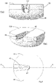
- Figs. 3-5 show views of an alternative backing 122 according to the present invention. It will be seen that the surface 130 is substantially planar except for a trough 40 formed in the backing 122.
- the trough 40 extends from a peripheral edge of the backing to a wall 42 which lies at the approximate centre of the backing 122.
- the hole 132 extends from the wall 42 to the peripheral edge of the backing 122.
- the hole 132 has a longitudinal axis A-A and in this embodiment the trough 40 shares the same longitudinal axis.
- the wall 42 surrounding the end of the hole 132 slopes towards the hole so as to provide a guide or lead-in for the free end of the post 14 during fitment.
- the side walls of the trough are angled relative to each other and taper towards the hole 132.
- the bottom of the trough 40 is aligned with the (bottom) edge of the hole 132.
- the tapering side walls and the bottom wall of the trough can thereby also act to guide the free end of the post 14 towards the hole during fitment.
- the backing 122 is a substantially circular disc.
- the periphery of the disc has two parallel flats 44, the flats 44 being aligned with the longitudinal axis A-A.
- the purpose of the flats 44 is to assist the user in aligning the trough 40 and hole 132 with the second portion 26 of the post during fitment.
- An alternative embodiment does not include flats and the backing is a circular disc.
- Fig.3 shows that the backing 122 has a domed (back) surface 46 opposing the planar (front) surface 130.
- the domed surface 46 helps to minimise localised regions of high pressure which might otherwise occur at the periphery of the back surface in the event that the backing is pressed against the user's neck, and which regions might cause discomfort over time (for example during sleeping).
- the domed surface 46 also helps the user to distinguish between the surfaces 130 and 46 by feel alone, and thereby to properly orient the backing 122 during fitment even if it is not visible.
- the depth of the trough 40 is less than the thickness of the backing 122, so that the trough does not extend all the way to the domed surface 46.
- the domed surface 46 is therefore continuous and aesthetically pleasing.
- the backing can if desired be made flesh coloured so as to be unobtrusive, being provided in a number of colours to suit different skin colours if desired.
- the trough is extended all the way through the backing 22 so that the surface 50 (which opposes the surface 30) is similarly discontinuous.
- the surface 50 is substantially planar.
- Fitting the backing 22 in its alternative orientation therefore varies the spacing between the portion 26 of the post 14 and the user's ear lobe 20. Accordingly, the backing 22 can be worn by users having different-thickness ear lobes, and/or can be used with earrings 10 having a different spacing between the stud 12 and the bend 24.
- the backing 122 of Figs. 3-5 cannot be reoriented.
- a range of backings with different thicknesses suited to different users and/or earrings can nevertheless be provided.
- washers or spacers can be used as required with different thickness ear lobes and/or different earrings.
- two (or perhaps more) pairs of backings 122 could be provided with each pair of stud earrings, the pairs of backings having different thicknesses suited to users with different thickness ear lobes.
- the significant cost benefit over a traditional butterfly clasp for example is expected to make it cost-effective to provide multiple backings with a set of earrings.
- the trough 40 can readily be located and positioned by touch alone; tests have demonstrated that some users find it easier to fit a backing 122 (with a trough which is open at the front surface of the backing only) than a backing 22 (with a trough which is open at the front and back surfaces of the backing).
- a backing 122 with a trough which is open at the front surface of the backing only
- a backing 22 with a trough which is open at the front and back surfaces of the backing.
- the bottom of the trough 40 is used to guide the free end of the post towards the hole as the backing is fitted to the post.
- Fig.6 shows a backing 222 which is similar to the backing 122 of Figs. 3-5 except that it does not have the flats 44 and instead is a disc with a circular periphery.
- the curvature of the back surface 246 has been extended and terminates adjacent to the hole 232. It will be understood that alternative embodiments could have an oval periphery, or a periphery comprising a number of straight edges (and combinations of these alternative shapes are also possible).
- Figs. 7 and 8 show another embodiment of backing 322 according to the present invention, which shares the reversible and offset hole features of the embodiment of Fig.2 and the ease of fitment features of Figs. 3-5 .
- the backing 322 is a substantially circular disc with a substantially planar first surface 330 and a substantially planar second surface 430.
- the backing 322 has a first trough 340 and a first hole 332.
- the first trough 340 is open to the first surface 330 of the backing but is not open to the second surface 430.
- the backing 322 has a second trough 440 and a second hole 432.
- the second trough 440 is open to the second surface 430 of the backing but in not open to the first surface 330. Because both of the troughs 340, 440 are open to only one of the opposing surfaces the user is better able to position and align the chosen trough and hole with the earring post in use.
- first trough 340 and first hole 332 are oriented at approximately 90° to the second trough 440 and second hole 432.
- a 90° separation has been found to be ideal for enabling a user to correctly position and align the chosen trough and hole (and for example a 180° separation has been found to cause potential confusion for the user).
- the depth of the first and second troughs differs whereby to provide some adjustment for the user.
- the first trough 340 has a depth D1 (i.e. from the first surface 330) and the second trough 440 has a depth D2 (i.e. from the second surface 430).
- the difference between the depths D1 and D2 might be around 1 mm for example, enabling the backing 322 to be used with ear lobe thicknesses differing by around 1 mm.
- the backing 322 can be used with a larger range of ear lobe thicknesses if it is made of a relatively compressible material (such as a soft silicone), and one or both of the depths D1 and D2 could be increased for example. Similarly, the thicknesses of the backings 22, 122 and 222 could be increased when a relatively compressible material is used.
- a relatively compressible material such as a soft silicone
- FIGs. 7 and 8 show a relatively sharp corner between the first surface 330 and the peripheral edge of the disc, and similarly a relatively sharp corner between the second surface 430 and the peripheral edge of the disc, in practice those corners would be rounded to increase the comfort for the user.
- the holes 32, 132, 232, 332, 432 are slightly smaller than the post 14 in order to provide the desired frictional grip.
- Practical embodiments of the invention have a backing 22, 122, 222 comprising a substantially circular disc with a diameter of between approx. 5 mm and 10 mm (larger diameter backings being suitable for heavier earrings).
- the hole 32, 232, 332, 432 may be around 0.5 mm in diameter and between approx. 2 and approx. 5 mm long (although the hole diameter in particular is dependent upon the flexibility and stretchability of the backing material). It is expected that such backings could be used with posts 14 having a diameter of approx. 0.6 mm to approx. 1 mm.
- the hole 32, 132, 232, 332, 432 extends to the approximate centre of the respective backing 22, 122, 222, 322. Accordingly, and as with the prior art arrangement of Fig.1 , the backing substantially surrounds the first portion 16 of the post 14 and consequently substantially surrounds the piercing 18. Such an arrangement is not essential and it would alternatively be possible for the hole to extend from one peripheral edge of the backing to the opposing peripheral edge. It is, however, preferable for the backing to surround the piercing as shown.
Landscapes
- Adornments (AREA)
Applications Claiming Priority (1)
| Application Number | Priority Date | Filing Date | Title |
|---|---|---|---|
| GBGB2101452.7A GB202101452D0 (en) | 2021-02-03 | 2021-02-03 | Backing for Earring, and Earring with a Backing |
Publications (3)
| Publication Number | Publication Date |
|---|---|
| EP4039122A1 true EP4039122A1 (fr) | 2022-08-10 |
| EP4039122C0 EP4039122C0 (fr) | 2025-08-06 |
| EP4039122B1 EP4039122B1 (fr) | 2025-08-06 |
Family
ID=74865469
Family Applications (1)
| Application Number | Title | Priority Date | Filing Date |
|---|---|---|---|
| EP22154800.1A Active EP4039122B1 (fr) | 2021-02-03 | 2022-02-02 | Supports de boucle d'oreille et boucle d'oreille dotée d'un support |
Country Status (3)
| Country | Link |
|---|---|
| US (2) | US20220330666A1 (fr) |
| EP (1) | EP4039122B1 (fr) |
| GB (1) | GB202101452D0 (fr) |
Cited By (1)
| Publication number | Priority date | Publication date | Assignee | Title |
|---|---|---|---|---|
| US20220330666A1 (en) * | 2021-02-03 | 2022-10-20 | Claire Lavinia Hewitt | Backing for an earring, and earring with a backing |
Families Citing this family (1)
| Publication number | Priority date | Publication date | Assignee | Title |
|---|---|---|---|---|
| FR3112067B1 (fr) * | 2020-07-03 | 2022-10-14 | Julie Genet | Système de maintien d'un piercing sans fermoir |
Citations (3)
| Publication number | Priority date | Publication date | Assignee | Title |
|---|---|---|---|---|
| US5201197A (en) * | 1992-06-01 | 1993-04-13 | Bakker Johann G | Pierced earring mount locking member |
| EP1498043A1 (fr) * | 2002-04-11 | 2005-01-19 | Nobuyuki Umehara | Mecanisme pour broche de verrouillage destinee aux ornements personnels |
| GB2572067A (en) | 2018-02-21 | 2019-09-18 | Lavinia Hewitt Claire | Stud earring |
Family Cites Families (20)
| Publication number | Priority date | Publication date | Assignee | Title |
|---|---|---|---|---|
| US483214A (en) * | 1892-09-27 | Ear-ring | ||
| US293958A (en) * | 1884-02-19 | Peters | ||
| US280726A (en) * | 1883-07-03 | William e | ||
| US3071938A (en) * | 1956-03-29 | 1963-01-08 | Davidson Frank Hodge | Ornament for pierced ears having pendant attaching means |
| US3446033A (en) * | 1964-12-18 | 1969-05-27 | Jesse L Driscoll | Earring including loss-preventing attaching device |
| CA1072759A (fr) * | 1977-11-01 | 1980-03-04 | Sheila Chicckine | Support pour boucles d'oreille |
| US4214456A (en) * | 1978-08-04 | 1980-07-29 | Hannum Evelyn J | Earring with unitary fastener |
| US4497186A (en) * | 1983-08-25 | 1985-02-05 | Mason Harry N | Earring with pendant and circumjacent spiral portion |
| US5170542A (en) * | 1990-10-29 | 1992-12-15 | Greenberg William H | Jewelry clutch |
| US5170641A (en) * | 1992-05-14 | 1992-12-15 | Didomenico Joseph | Pin adaptor for pierced earrings |
| US5582037A (en) * | 1993-06-07 | 1996-12-10 | Didomenico; Joseph | Pierced earring assembly |
| US5638700A (en) * | 1996-01-11 | 1997-06-17 | Shechter; Jaime | Earring post |
| US6925838B1 (en) * | 2002-03-25 | 2005-08-09 | Jacqueline M. Carmack | Earring support device |
| US20050092022A1 (en) * | 2002-04-11 | 2005-05-05 | Nobuyuki Umehara | Mechanism for locking pin for personal ornaments |
| US7337632B2 (en) * | 2005-10-19 | 2008-03-04 | Findings Incorporated | Earring with floating decorative element |
| US8695183B2 (en) * | 2007-07-18 | 2014-04-15 | Melecy M. Kent | Earring backing |
| US20100024479A1 (en) * | 2008-07-29 | 2010-02-04 | Yvonne Palko Corona | Fastener for securing jewelry item |
| US9392849B1 (en) * | 2013-12-11 | 2016-07-19 | Richline Group | Multifunctional decorative jewelry element |
| GB202101452D0 (en) * | 2021-02-03 | 2021-03-17 | Hewitt Claire Lavinia | Backing for Earring, and Earring with a Backing |
| US11399602B1 (en) * | 2021-02-23 | 2022-08-02 | Carmela Max Ciatto Corso | Earring back supporter with additional ornament |
-
2021
- 2021-02-03 GB GBGB2101452.7A patent/GB202101452D0/en not_active Ceased
-
2022
- 2022-02-02 EP EP22154800.1A patent/EP4039122B1/fr active Active
- 2022-02-03 US US17/591,645 patent/US20220330666A1/en not_active Abandoned
-
2024
- 2024-07-08 US US18/765,414 patent/US20240358125A1/en not_active Abandoned
Patent Citations (3)
| Publication number | Priority date | Publication date | Assignee | Title |
|---|---|---|---|---|
| US5201197A (en) * | 1992-06-01 | 1993-04-13 | Bakker Johann G | Pierced earring mount locking member |
| EP1498043A1 (fr) * | 2002-04-11 | 2005-01-19 | Nobuyuki Umehara | Mecanisme pour broche de verrouillage destinee aux ornements personnels |
| GB2572067A (en) | 2018-02-21 | 2019-09-18 | Lavinia Hewitt Claire | Stud earring |
Cited By (2)
| Publication number | Priority date | Publication date | Assignee | Title |
|---|---|---|---|---|
| US20220330666A1 (en) * | 2021-02-03 | 2022-10-20 | Claire Lavinia Hewitt | Backing for an earring, and earring with a backing |
| US20240358125A1 (en) * | 2021-02-03 | 2024-10-31 | Claire Lavinia Hewitt | Backing for an earring, and earring with a backing |
Also Published As
| Publication number | Publication date |
|---|---|
| US20220330666A1 (en) | 2022-10-20 |
| GB202101452D0 (en) | 2021-03-17 |
| US20240358125A1 (en) | 2024-10-31 |
| EP4039122C0 (fr) | 2025-08-06 |
| EP4039122B1 (fr) | 2025-08-06 |
Similar Documents
| Publication | Publication Date | Title |
|---|---|---|
| US20240358125A1 (en) | Backing for an earring, and earring with a backing | |
| US4593540A (en) | Pierced earring with slidable plastic post and backing | |
| US5946943A (en) | Body piercing jewelry | |
| EP2166893B1 (fr) | Support de boucle d'oreille | |
| US4704878A (en) | Earring | |
| US5444994A (en) | Pressure displacement device | |
| US5454829A (en) | Pierced ear lobe saver | |
| US4796443A (en) | Comfort earring clip | |
| US20260007214A1 (en) | Backing for an earring, and earring with a backing | |
| GB2572067A (en) | Stud earring | |
| JP3310466B2 (ja) | 装身用ピアス | |
| US8752402B1 (en) | Jewelry and method of wearing | |
| US20200253342A1 (en) | Ornamental earring backing without hole | |
| JP3169358U (ja) | 磁石を用いた耳飾り用脱落防止金具、及びそれを備えた耳飾り | |
| JP3214012U (ja) | ピアスの取付具 | |
| US20100122553A1 (en) | Pierced jewelry retainment system | |
| WO2009009517A1 (fr) | Adaptateur pour bijoux | |
| CN204351220U (zh) | 吊坠固定座及首饰 | |
| JP3247867U (ja) | 高密着イヤリング | |
| JP3022781B2 (ja) | イヤリング | |
| JP3026056U (ja) | 耳飾り | |
| GB2321385A (en) | Decorative ear accessory | |
| JP2012034833A (ja) | イヤリングの止め具 | |
| JP3014560U (ja) | 耳のピアス装着時に穴あけした穴の収縮を防止し、耳たぶの厚みに対応して止め幅が調整可能で、かつ、金属アレルギーを引き起こす確率の極めて低い材料を使用して製造したファッションピアス | |
| JP3035500U (ja) | 耳掛け用イヤリング |
Legal Events
| Date | Code | Title | Description |
|---|---|---|---|
| PUAI | Public reference made under article 153(3) epc to a published international application that has entered the european phase |
Free format text: ORIGINAL CODE: 0009012 |
|
| STAA | Information on the status of an ep patent application or granted ep patent |
Free format text: STATUS: THE APPLICATION HAS BEEN PUBLISHED |
|
| AK | Designated contracting states |
Kind code of ref document: A1 Designated state(s): AL AT BE BG CH CY CZ DE DK EE ES FI FR GB GR HR HU IE IS IT LI LT LU LV MC MK MT NL NO PL PT RO RS SE SI SK SM TR |
|
| STAA | Information on the status of an ep patent application or granted ep patent |
Free format text: STATUS: REQUEST FOR EXAMINATION WAS MADE |
|
| 17P | Request for examination filed |
Effective date: 20230512 |
|
| RBV | Designated contracting states (corrected) |
Designated state(s): AL AT BE BG CH CY CZ DE DK EE ES FI FR GB GR HR HU IE IS IT LI LT LU LV MC MK MT NL NO PL PT RO RS SE SI SK SM TR |
|
| GRAP | Despatch of communication of intention to grant a patent |
Free format text: ORIGINAL CODE: EPIDOSNIGR1 |
|
| STAA | Information on the status of an ep patent application or granted ep patent |
Free format text: STATUS: GRANT OF PATENT IS INTENDED |
|
| INTG | Intention to grant announced |
Effective date: 20250226 |
|
| GRAS | Grant fee paid |
Free format text: ORIGINAL CODE: EPIDOSNIGR3 |
|
| GRAA | (expected) grant |
Free format text: ORIGINAL CODE: 0009210 |
|
| STAA | Information on the status of an ep patent application or granted ep patent |
Free format text: STATUS: THE PATENT HAS BEEN GRANTED |
|
| AK | Designated contracting states |
Kind code of ref document: B1 Designated state(s): AL AT BE BG CH CY CZ DE DK EE ES FI FR GB GR HR HU IE IS IT LI LT LU LV MC MK MT NL NO PL PT RO RS SE SI SK SM TR |
|
| RAP3 | Party data changed (applicant data changed or rights of an application transferred) |
Owner name: HEWITT, CLAIRE LAVINIA |
|
| REG | Reference to a national code |
Ref country code: GB Ref legal event code: FG4D |
|
| RIN1 | Information on inventor provided before grant (corrected) |
Inventor name: HEWITT, CLAIRE LAVINIA |
|
| REG | Reference to a national code |
Ref country code: CH Ref legal event code: EP |
|
| REG | Reference to a national code |
Ref country code: IE Ref legal event code: FG4D |
|
| REG | Reference to a national code |
Ref country code: DE Ref legal event code: R096 Ref document number: 602022018690 Country of ref document: DE |
|
| U01 | Request for unitary effect filed |
Effective date: 20250807 |
|
| U07 | Unitary effect registered |
Designated state(s): AT BE BG DE DK EE FI FR IT LT LU LV MT NL PT RO SE SI Effective date: 20250813 |
|
| U1N | Appointed representative for the unitary patent procedure changed after the registration of the unitary effect |
Representative=s name: STEVENS HEWLETT & PERKINS; GB |
|
| PG25 | Lapsed in a contracting state [announced via postgrant information from national office to epo] |
Ref country code: IS Free format text: LAPSE BECAUSE OF FAILURE TO SUBMIT A TRANSLATION OF THE DESCRIPTION OR TO PAY THE FEE WITHIN THE PRESCRIBED TIME-LIMIT Effective date: 20251206 |
|
| PGFP | Annual fee paid to national office [announced via postgrant information from national office to epo] |
Ref country code: GB Payment date: 20251210 Year of fee payment: 5 |
|
| PG25 | Lapsed in a contracting state [announced via postgrant information from national office to epo] |
Ref country code: NO Free format text: LAPSE BECAUSE OF FAILURE TO SUBMIT A TRANSLATION OF THE DESCRIPTION OR TO PAY THE FEE WITHIN THE PRESCRIBED TIME-LIMIT Effective date: 20251106 |
|
| U20 | Renewal fee for the european patent with unitary effect paid |
Year of fee payment: 5 Effective date: 20251210 |
|
| PG25 | Lapsed in a contracting state [announced via postgrant information from national office to epo] |
Ref country code: HR Free format text: LAPSE BECAUSE OF FAILURE TO SUBMIT A TRANSLATION OF THE DESCRIPTION OR TO PAY THE FEE WITHIN THE PRESCRIBED TIME-LIMIT Effective date: 20250806 |
|
| PG25 | Lapsed in a contracting state [announced via postgrant information from national office to epo] |
Ref country code: GR Free format text: LAPSE BECAUSE OF FAILURE TO SUBMIT A TRANSLATION OF THE DESCRIPTION OR TO PAY THE FEE WITHIN THE PRESCRIBED TIME-LIMIT Effective date: 20251107 |
|
| PG25 | Lapsed in a contracting state [announced via postgrant information from national office to epo] |
Ref country code: PL Free format text: LAPSE BECAUSE OF FAILURE TO SUBMIT A TRANSLATION OF THE DESCRIPTION OR TO PAY THE FEE WITHIN THE PRESCRIBED TIME-LIMIT Effective date: 20250806 |
|
| PG25 | Lapsed in a contracting state [announced via postgrant information from national office to epo] |
Ref country code: RS Free format text: LAPSE BECAUSE OF FAILURE TO SUBMIT A TRANSLATION OF THE DESCRIPTION OR TO PAY THE FEE WITHIN THE PRESCRIBED TIME-LIMIT Effective date: 20251106 |
|
| PG25 | Lapsed in a contracting state [announced via postgrant information from national office to epo] |
Ref country code: ES Free format text: LAPSE BECAUSE OF FAILURE TO SUBMIT A TRANSLATION OF THE DESCRIPTION OR TO PAY THE FEE WITHIN THE PRESCRIBED TIME-LIMIT Effective date: 20250806 |
|
| PG25 | Lapsed in a contracting state [announced via postgrant information from national office to epo] |
Ref country code: SM Free format text: LAPSE BECAUSE OF FAILURE TO SUBMIT A TRANSLATION OF THE DESCRIPTION OR TO PAY THE FEE WITHIN THE PRESCRIBED TIME-LIMIT Effective date: 20250806 |