EP4039150B1 - Procédé de nettoyage à l'aide d'un robot nettoyeur et robot nettoyeur - Google Patents
Procédé de nettoyage à l'aide d'un robot nettoyeur et robot nettoyeur Download PDFInfo
- Publication number
- EP4039150B1 EP4039150B1 EP22150881.5A EP22150881A EP4039150B1 EP 4039150 B1 EP4039150 B1 EP 4039150B1 EP 22150881 A EP22150881 A EP 22150881A EP 4039150 B1 EP4039150 B1 EP 4039150B1
- Authority
- EP
- European Patent Office
- Prior art keywords
- cleaning
- cleaning robot
- dpu
- robot
- max
- Prior art date
- Legal status (The legal status is an assumption and is not a legal conclusion. Google has not performed a legal analysis and makes no representation as to the accuracy of the status listed.)
- Active
Links
Images


Classifications
-
- A—HUMAN NECESSITIES
- A47—FURNITURE; DOMESTIC ARTICLES OR APPLIANCES; COFFEE MILLS; SPICE MILLS; SUCTION CLEANERS IN GENERAL
- A47L—DOMESTIC WASHING OR CLEANING; SUCTION CLEANERS IN GENERAL
- A47L9/00—Details or accessories of suction cleaners, e.g. mechanical means for controlling the suction or for effecting pulsating action; Storing devices specially adapted to suction cleaners or parts thereof; Carrying-vehicles specially adapted for suction cleaners
-
- A—HUMAN NECESSITIES
- A47—FURNITURE; DOMESTIC ARTICLES OR APPLIANCES; COFFEE MILLS; SPICE MILLS; SUCTION CLEANERS IN GENERAL
- A47L—DOMESTIC WASHING OR CLEANING; SUCTION CLEANERS IN GENERAL
- A47L9/00—Details or accessories of suction cleaners, e.g. mechanical means for controlling the suction or for effecting pulsating action; Storing devices specially adapted to suction cleaners or parts thereof; Carrying-vehicles specially adapted for suction cleaners
- A47L9/28—Installation of the electric equipment, e.g. adaptation or attachment to the suction cleaner; Controlling suction cleaners by electric means
- A47L9/2836—Installation of the electric equipment, e.g. adaptation or attachment to the suction cleaner; Controlling suction cleaners by electric means characterised by the parts which are controlled
- A47L9/2852—Elements for displacement of the vacuum cleaner or the accessories therefor, e.g. wheels, casters or nozzles
-
- A—HUMAN NECESSITIES
- A47—FURNITURE; DOMESTIC ARTICLES OR APPLIANCES; COFFEE MILLS; SPICE MILLS; SUCTION CLEANERS IN GENERAL
- A47L—DOMESTIC WASHING OR CLEANING; SUCTION CLEANERS IN GENERAL
- A47L9/00—Details or accessories of suction cleaners, e.g. mechanical means for controlling the suction or for effecting pulsating action; Storing devices specially adapted to suction cleaners or parts thereof; Carrying-vehicles specially adapted for suction cleaners
- A47L9/009—Carrying-vehicles; Arrangements of trollies or wheels; Means for avoiding mechanical obstacles
-
- A—HUMAN NECESSITIES
- A47—FURNITURE; DOMESTIC ARTICLES OR APPLIANCES; COFFEE MILLS; SPICE MILLS; SUCTION CLEANERS IN GENERAL
- A47L—DOMESTIC WASHING OR CLEANING; SUCTION CLEANERS IN GENERAL
- A47L9/00—Details or accessories of suction cleaners, e.g. mechanical means for controlling the suction or for effecting pulsating action; Storing devices specially adapted to suction cleaners or parts thereof; Carrying-vehicles specially adapted for suction cleaners
- A47L9/28—Installation of the electric equipment, e.g. adaptation or attachment to the suction cleaner; Controlling suction cleaners by electric means
- A47L9/2868—Arrangements for power supply of vacuum cleaners or the accessories thereof
- A47L9/2884—Details of arrangements of batteries or their installation
-
- G—PHYSICS
- G05—CONTROLLING; REGULATING
- G05D—SYSTEMS FOR CONTROLLING OR REGULATING NON-ELECTRIC VARIABLES
- G05D1/00—Control of position, course, altitude or attitude of land, water, air or space vehicles, e.g. using automatic pilots
- G05D1/02—Control of position or course in two dimensions
- G05D1/021—Control of position or course in two dimensions specially adapted to land vehicles
- G05D1/0212—Control of position or course in two dimensions specially adapted to land vehicles with means for defining a desired trajectory
- G05D1/0223—Control of position or course in two dimensions specially adapted to land vehicles with means for defining a desired trajectory involving speed control of the vehicle
-
- A—HUMAN NECESSITIES
- A47—FURNITURE; DOMESTIC ARTICLES OR APPLIANCES; COFFEE MILLS; SPICE MILLS; SUCTION CLEANERS IN GENERAL
- A47L—DOMESTIC WASHING OR CLEANING; SUCTION CLEANERS IN GENERAL
- A47L2201/00—Robotic cleaning machines, i.e. with automatic control of the travelling movement or the cleaning operation
-
- A—HUMAN NECESSITIES
- A47—FURNITURE; DOMESTIC ARTICLES OR APPLIANCES; COFFEE MILLS; SPICE MILLS; SUCTION CLEANERS IN GENERAL
- A47L—DOMESTIC WASHING OR CLEANING; SUCTION CLEANERS IN GENERAL
- A47L2201/00—Robotic cleaning machines, i.e. with automatic control of the travelling movement or the cleaning operation
- A47L2201/04—Automatic control of the travelling movement; Automatic obstacle detection
Definitions
- the present invention relates to a method for cleaning a floor area in a private household using a cleaning robot.
- the invention also relates to a cleaning robot for carrying out the method.
- Cleaning robots such as vacuum or mop robots are increasingly being used in private households to clean floors. Due to their light weight and small construction volume, household cleaning robots can also clean floors in narrow spaces. There are also commercially used cleaning robots for industrial cleaning, for example in airports and halls, which are equipped with very large battery capacity and dirt absorption capacity for autonomous cleaning of corresponding large areas. Industrial cleaning robots are therefore correspondingly heavy and have a large construction volume.
- the object of the invention is to be able to clean apartments in private households in an improved manner.
- the object of the invention is achieved with a method having the features of the first claim.
- a cleaning robot comprises the features of the secondary claim for carrying out the method.
- a method for cleaning an area in a private household with a cleaning robot that is equipped with at least one sensor for detecting obstacles and for mapping the environment and/or carries out a cleaning run according to a route planned on the basis of sensor signals from the sensor.
- the cleaning robot has wheels for moving in a direction of travel and a cleaning mechanism for cleaning.
- the wheels and the cleaning mechanism are driven by at least one electric motor that is supplied with electrical energy using at least one battery of the cleaning robot.
- the wheels allow the cleaning robot to be moved without a user having to pull or push the cleaning robot for cleaning.
- the height of the cleaning robot is between 0.12 m and 0.5 m.
- the cleaning robot cannot therefore vacuum under pieces of furniture under which cleaning robots with a height of, for example, 10 cm or less vacuum. can.
- the weight W of the cleaning robot is less than 20 kg.
- the maximum possible operating speed of the cleaning robot is less than 1.50 km/h.
- the cleaning robot cannot therefore be moved faster than 1.50 km/h during automated cleaning.
- the area performance A of the cleaning robot is at least 220 m 2 at DPU>50%.
- the area performance is less than 950 m 2 .
- the area performance A with the unit [m 2 ] describes the size of an area that can be cleaned after all batteries of the cleaning robot have been fully charged at DPU > 50% or at the maximum speed v max at DPU > 50%.
- a cleaning robot in the sense of the present disclosure is a robot that can pick up particles.
- a cleaning robot can clean a surface without a user being required during the cleaning process.
- the cleaning robot can be a vacuum robot or a mop robot.
- a mop robot has a wiping element, for example a rag, mop, sponge or cleaning fabric.
- the wiping element can pick up water.
- a mop robot can have a fan for sucking up dirt and/or be set up so that the wiping element can be moved translationally and/or rotationally relative to the housing of the mop robot in order to pick up dirt particles.
- the wiping element is detachably attached to the mop robot and can be removed and replaced by the user for cleaning.
- a vacuum robot can independently clean a surface by vacuuming.
- the vacuum robot has a fan through which air can be sucked in.
- the vacuum robot has a container in which sucked-up particles are collected.
- the vacuum robot has at least one filter through which sucked-in air laden with particles is separated from dust. The air cleaned in this way is then blown out of the vacuum robot. If the vacuum robot essentially cleans a surface by sucking in dirt through a nozzle or suction opening, the cleaning width can correspond to the width of the nozzle or suction opening.
- Such vacuum robots can be used, for example, to clean laminate flooring. For cleaning carpets or areas with carpet and hard floors, for example, a vacuum robot preferably has a sweeping unit that helps pick up particles. Even a cleaning robot that cannot vacuum has a sweeping unit in one design.
- the sweeping unit can be a sweeping roller that is rotatably mounted and driven by the motor during cleaning.
- a sweeping roller is provided in particular with protruding bristles, strips and/or knobs in order to be able to transport particles into a vacuum robot.
- the cleaning width can be simplified to be the same as the width of the sweeping roller.
- the sweeping unit can comprise one or two corner brushes.
- a corner brush can rotate around a vertical axis of rotation like a cup brush.
- a sweeping unit can consist of two corner brushes without a sweeping roller. With such a cleaning mechanism, the dirt is brushed under or into the cleaning robot by the corner brushes with or without suction.
- a cleaning robot can be designed for different applications.
- cleaning robots for industrial use that are designed to clean large areas, for example an airport or halls, and therefore clean areas of 500 m 2 and more.
- such industrial cleaning robots are particularly powerful and can be moved particularly quickly.
- the usual maximum possible operating speeds S max of such industrial cleaning robots are significantly more than 1.50 km/h.
- a cleaning robot designed for industrial purposes is therefore large and heavy compared to a cleaning robot that is intended for cleaning private households.
- the maximum running time T is the operating time that is possible with a full charge of the battery or batteries of the cleaning robot at the maximum speed v max that just meets the criterion DPU > 50% over the cleaning width.
- Full charge means that all of the cleaning robot's batteries are fully charged at the start of a time measurement.
- DPU means the dust pickup.
- the measurement can be taken on a hard floor, preferably made of untreated laminated pine plywood, in particular with a thickness of at least 15 mm.
- the measurement can be taken on carpet, preferably Wilton carpet, in particular in accordance with IEC TS 62885-1.
- a preferred measurement setup for both hard floors and carpets is specified in the IEC-62885-7 standard in the version valid on the filing date, especially for medium debris. This also applies to the other parameters such as fiber pickup, coarse debris pickup, maximum speed at DPU > 50% and the corresponding parameters for determining the area performance.
- DPU stands for "dust pick-up rate".
- DPU>50% means that the dust pickup from the area to be cleaned is more than 50%.
- the cleaning width is the width transverse to the direction of travel, which the cleaning robot is able to clean when moving forward in the direction of travel during a cleaning run with DPU > 50%.
- a cleaning robot for a household should also be able to vacuum under pieces of furniture such as beds and sofas. For this reason, a low installation height is desired for such a cleaning robot.
- the diameter of such a cleaning robot or its maximum extent parallel to the area to be cleaned should be relatively small so that it can also drive into narrow spaces in order to be able to clean there.
- the performance is low and the maximum possible operating speed is less than 1.50 km/h.
- An example of such a household cleaning robot is the VR300 from Vortechnik, which is already considered to be particularly powerful among household cleaning robots.
- the area performance A of the VR300 cleaning robot, ie with DPU > 50%, is 129.6 m 2 . Its maximum possible operating speed is 1.2 km/h.
- the area is cleaned by the cleaning robot at least twice a day for at least one week, with at least one piece of furniture with a clearance height of no more than 10 cm on the area to be cleaned.
- the invention is based on the knowledge explained below.
- a cleaning robot can therefore only remove dust from under the piece of furniture if the height of the cleaning robot is less than 10 cm.
- the height of more than 0.12 m ensures that the The cleaning robot according to the invention does not clean areas into which dust and particles do not directly reach.
- a maximum possible operating speed of the cleaning robot of less than 1.50 km/h ensures that the cleaning robot cannot be moved at an excessively high speed during cleaning. An excessively high speed could damage furniture in private households. This is avoided by limiting the speed.
- the stopping distance can thus be reduced and safety increased. This is particularly important in this case because the mass of the cleaning robot is comparatively large compared to conventional household cleaning robots.
- the area performance is at least 220 m 2 at a DPU of 50%.
- a relatively large width of the sweeping roller is therefore regularly required in order to achieve the area performance despite the relatively low speed.
- a cleaning robot according to the invention is therefore generally wider than conventional cleaning robots used in private households. Therefore, not only areas under pieces of furniture with a low clearance height are necessarily excluded from cleaning, but also narrow areas, which are also typically not immediately and therefore hardly soiled.
- the area to be cleaned is cleaned by the cleaning robot at least twice a day for at least a week, the areas that get dirty easily and repeatedly are cleaned at a high frequency. Due to the design of the cleaning robot, areas that hardly get dirty are necessarily excluded, and especially not if adjacent areas, i.e. adjacent surfaces, are cleaned at a high frequency.
- the invention therefore ensures that cleaning is carried out where it is required and that unnecessary areas are excluded without having to program this. Unnecessary cleaning is thus avoided to save time. Disturbances caused by frequent cleaning are thus minimized.
- the cleaning robot according to the invention It is therefore important for the cleaning robot according to the invention that it achieves a large surface area performance in order to cause as little disruption as possible, since according to the invention it is basically used at least twice a day for a longer period of time. On the other hand, it is not important that such a cleaning robot has complicated navigation properties in order to reliably clean narrow spaces, for example.
- the design of the cleaning robot basically ensures that time-consuming maneuvering due to narrow spaces is minimized.
- the construction height is preferably no more than 0.5 m in order to be able to vacuum under dining tables.
- the construction height is particularly preferably no more than 0.4 m in order to be able to vacuum under normal high chairs.
- the invention also relates to a cleaning robot for carrying out the method.
- the cleaning robot is equipped with at least one sensor for detecting obstacles and for mapping the environment and/or for carrying out a cleaning run according to a route planned on the basis of sensor signals from the sensor.
- Sensor signals can be analog or digital signals.
- the sensor preferably emits analog measured values.
- a signal processing unit can be provided to process the analog measured values and provide digital sensor signals.
- the sensor signals contain information about a distance, an obstacle and/or a particular geometric environmental property.
- Such a cleaning robot is therefore a so-called "intelligent" cleaning robot with a mapping system.
- there is also another class of cleaning robots which, to put it simply, essentially always drive straight ahead and only change direction when they collide with an obstacle in order to drive over an area to be cleaned in a random manner.
- the cleaning robot has wheels for moving in a direction of travel and a cleaning mechanism for cleaning.
- the wheels and the cleaning mechanism are driven by at least one motor, which is supplied with electrical energy by means of at least one battery of the cleaning robot.
- the cleaning robot is a vacuum robot, it comprises a Fan through which air can be sucked in, a container in which sucked-in particles are collected, and at least one filter through which sucked-in particle-laden air is separated from dust.
- the vacuum robot can comprise a sweeping unit driven by the motor, which as a component of the cleaning mechanism supports the collection of particles.
- the sweeping unit in a vacuum robot is a sweeping roller. The sweeping roller rotates during cleaning. This allows particles on the surface to be cleaned to be picked up and transported into the vacuum robot.
- the cleaning robot can be a sweeping robot that cannot vacuum.
- the cleaning mechanism then comprises a sweeping unit that can be moved by the motor and has one or more sweeping brushes, such as corner brushes, with which dirt particles (without suction) on the surface to be cleaned are picked up and transported into the cleaning robot.
- the cleaning robot can be a mopping robot in which the cleaning mechanism comprises a mopping element for cleaning by wet mopping.
- the height of the cleaning robot is 0.12 m to 0.5 m.
- the weight W of the cleaning robot is less than 20 kg.
- the maximum possible operating speed of the cleaning robot is less than 1.50 km/h.
- the maximum possible operating speed is preferably achieved by a controlled reduction in speed, so that on floors with higher frictional resistance, e.g. carpets, the same maximum possible operating speed can be achieved as on floors with lower frictional resistance, e.g. hard floors.
- the area performance A at DPU>50% of the cleaning robot is 220 m 2 to 950 m 2 .
- the cleaning width is the width transverse to the direction of travel that the cleaning robot is able to clean when moving forward in the direction of travel during a cleaning run.
- the special feature of the cleaning robot is that it is optimized for the application of cleaning the areas in a private household that are easily soiled at high frequency. Its design ensures that areas that are not easily soiled are regularly left out. In order for the cleaning robot to be able to vacuum at high frequency, its The area performance is large compared to the area performance of conventional cleaning robots that are used in private households.
- the cleaning robot according to the invention differs from conventional industrial cleaning robots primarily in its relatively low maximum possible operating speed.
- the maximum energy content per battery is 100 Wh. In one embodiment, the total energy content of the one battery or of the multiple batteries is at least 100 Wh and/or at most 200 Wh.
- the energy content therefore relates to the sum of the batteries if multiple batteries are provided. This selection has proven to be particularly suitable for being able to use the cleaning robot in the manner mentioned.
- the energy content of such a battery is significantly greater than the energy content of a battery for a cleaning robot that is usually intended for use in private households.
- the energy content of the battery is significantly lower than the energy content of a battery as is regularly provided for an industrial cleaning robot.
- the cleaning robot is supplied with electrical energy by exactly two batteries.
- a battery is a battery that can be recharged.
- a battery is a structural unit that can be arranged spatially separate from another battery in the cleaning robot.
- the battery can be manually removed from the cleaning robot by the user for charging and reinserted.
- a permanently installed battery is also possible, which is charged, for example, via a cable or electrical contacts for connecting to a station.
- a battery can also be referred to as a battery pack.
- the provision of exactly two or more than two battery packs has the advantage that the weight of the batteries can be suitably distributed.
- the battery or batteries are preferably designed so that they can be fully recharged within three hours. This also ensures that the cleaning robot can clean an area of a floor in a private household several times a day.
- the weight W of the cleaning robot is more than 5 kg, preferably at least 6 kg, and/or at most 18 kg.
- the desired properties can be provided by this.
- the weight W of the cleaning robot is in particular, not more than 13 kg. Tests have shown that a cleaning robot weighing, for example, 8 kg achieves the desired properties in a particularly optimal manner. The weight of the cleaning robot therefore exceeds the weight of a conventional cleaning robot that is intended to vacuum in private households.
- the weight can be influenced by the selection of batteries to provide a desired energy content.
- the filter area of a cleaning robot is at least 329 cm 2 , particularly preferably more than 450 cm 2 .
- the cleaning robot according to the invention takes advantage of the fact that it is relatively large compared to conventional cleaning robots for private households and can therefore also provide space for a large filter area. Large filter areas have the advantage that air flow losses can be kept low.
- the filter area specified above can be used to achieve a maximum speed and a maximum running time T to achieve an area performance of between at least 300 m 2 and/or at most 950 m 2 particularly reliably at DPU > 50%.
- the maximum running time T can also be determined mathematically using the total energy content (or a capacity value) of the battery(s) and the power consumption of the cleaning robot for cleaning an area at DPU > 50% instead of using a measurement.
- the filter area refers to the area of the filter or filters intended for filtering dirty air that is sucked in.
- the filter area is therefore not contributed to, for example, by a filter frame made of plastic or cardboard, but only by a filter material, for example a filter membrane of the filter.
- the filter material is designed in such a way that it efficiently and effectively filters dirt from air that flows through the filter material.
- the filter area refers in particular to the filter, i.e. the filter component that can be changed or cleaned by the user, e.g. a dust bag or a dust separator.
- the filter area refers to the air passage area through one or more filtering materials of the filter.
- a filter component for replacement has a structure that includes a double membrane or several filter membrane layers one behind the other, all of which extend over a common air passage area
- this filter has the same filter area as a single-membrane filter with the same air passage area.
- the filter area refers to the unfolded area.
- a HEPA filter material is used, preferably certified according to the EN 1822 standard.
- the filter material contains or is fleece.
- the filter or the filter material is or contains a porous fluoroplastic film, preferably a PTFE membrane, for air filters.
- the filter or the filter material is or contains spunbound non-woven fabric, preferably one or two layers, each weighing at least 5 g/m 2 and/or at most 100 g/m 2 .
- the thickness of the filter material is preferably at least 0.1 mm and/or at most 1 mm.
- the filter material is preferably folded in a zigzag shape and/or fastened in a preferably rectangular frame.
- a multi-layer or multi-layer arrangement is provided, preferably with three or exactly three layers.
- the separation efficiency of the filter is at least 80%, preferably at least 90%, particularly preferably approximately or exactly 99.97%, in particular with a particle size of 0.3 to 0.5 ⁇ m.
- a filter with a pressure drop (at the filter surface) of at least 130 Pa and/or at most 220 Pa is provided, particularly preferably with a pressure drop of approximately or exactly 170 Pa.
- a thickness of a layer of the filter material is 0.32 mm or the total thickness of a multi-layer filter material is 0.32 mm.
- the filter material or the filter surface has a weight of 85 g / m 2 .
- the filter area of the cleaning robot is preferably no more than 900 cm 2 , particularly preferably no more than 700 cm 2 .
- Such a filter area is smaller than a filter area that can be provided for an industrial cleaning robot. This avoids the cleaning robot having to be built excessively large, which would be disadvantageous for its intended use in private households.
- the maximum blower power of a cleaning robot designed in particular as a vacuum robot is at least 25 W. It has proven to be expedient to select a blower power of at least 25 W. A maximum blower power of, for example, 27 watts is also provided for other cleaning robots that are used in private households.
- the blower power of the cleaning robot according to the invention can therefore be comparable to the blower power of a cleaning robot that is used in a private household is used. The reason is that the cleaning robot according to the invention is also intended to be used in a private household and consequently comparable requirements in terms of particle absorption must be met.
- the battery capacity that would be needed for a higher blower power is used in this case for a longer cleaning range or to reduce the battery capacity and thus the weight in order to support the effect according to the invention particularly effectively.
- the maximum blower power is preferably no more than 30 W. This means that the blower power is in the same order of magnitude as that provided for in other cleaning robots that are used in private households. Blower power in industrial cleaning robots can be significantly higher, since other requirements may have to be taken into account here.
- the construction volume BV of the cleaning robot is more than 10 L (liters), preferably at least 11 L, preferably at least 15 L.
- the construction volume is therefore larger than the construction volume of conventional cleaning robots that are used in private households.
- Construction volume means the volume that is determined from the external dimensions.
- the cleaning robot according to the invention is not built too small so that it spends as little time as possible cleaning areas that only need to be cleaned rarely.
- the construction volume of the cleaning robot is preferably BV ⁇ 40 L, particularly preferably BV ⁇ 30 L, since the cleaning robot according to the invention should not be built too large for its intended use in a private household.
- the construction volume of an industrial cleaning robot can be significantly larger than 40 L.
- the volume flow at the suction nozzle of the cleaning robot can be 10 to 14 l/s (liters per second). This is the volume flow that is typical for a cleaning robot for private households.
- the suction nozzle can be a suction opening on the cleaning robot through which dirt is sucked up from the floor and transported to the filter.
- the volume flow has been selected because the cleaning robot is intended to be used in private households and is therefore intended to remove particles that usually occur in private households in the form of dirt.
- the volume flow can be significantly higher because industrial use may have other requirements that may require larger volume flows at the nozzle.
- the volume flow of the blower can be at least 20 l/s and/or up to a maximum of 40 l/s or a maximum of 60 l/s (litres per second).
- this volume flow corresponds to the volume flow that is usual for cleaning robots that are intended for use in private households.
- larger volume flows can be provided due to other requirements.
- the cleaning width is at least 25 cm, preferably at least 28 cm, and/or at most 35 cm, preferably at most 32 cm.
- the cleaning robot comprises a sweeping roller
- the sweeping roller has a width of at least 25 cm, preferably at least 28 cm, and/or at most 35 cm, preferably at most 32 cm.
- the range between 25 cm and 35 cm corresponds to the range between usual cleaning widths of robot cleaners used in private households.
- Usual sweeping rollers of robot cleaners used in the industrial sector often have a width of at least 32 cm. The fact is taken into account that areas are to be cleaned in one day that lie between the areas that a cleaning robot for the private household is usually to clean daily and the areas that an industrial cleaning robot is usually to clean daily.
- the maximum speed v max is at least 0.3 m/s at DPU > 50%. This enables particularly efficient cleaning of remote locations to which dirt is usually transported by air currents. The slower the cleaning robot moves in the direction of travel, the greater the DPU value, and the faster the cleaning robot moves in the direction of travel, the lower the DPU value accordingly.
- the maximum speed at DPU > 50% is exactly the speed at which the cleaning robot just about achieves at least DPU > 50%.
- a cleaning robot that is usually used in private households can usually only achieve cleaning with DPU > 50% at slower speeds of, for example, 0.2 m/s.
- the maximum speed v max is approximately or at most 0.415 m/s at DPU > 50%.
- the area performance A of the cleaning robot is preferably at least 500 m 2 , particularly preferably at least 600 m 2 with DPU>50%.
- An upper limit for the stated application is an area performance of no more than 900 m 2 , since in practice there is basically no need for even higher area performances.
- the area performance with a value of 500 m 2 or more of the The cleaning robot according to the invention is therefore significantly higher than the area performance of conventional cleaning robots used in private households.
- an upper limit of 900 m 2 the area performance of the cleaning robot according to the invention does not come close to the area performance that industrial cleaning robots can usually achieve.
- the maximum dust absorption DPU is less than 80%, preferably less than 70%. Since the cleaning robot according to the invention is intended for frequent use, there is no problem of having to remove dirt that has been trodden on. The maximum dust absorption can therefore be limited to 80% or 70% in order to be able to keep the technical effort for the cleaning robot according to the invention within reasonable limits.
- the maximum dust absorption DPU is measured in particular in accordance with the IEC 62885 standard. In a technically more complex embodiment, the maximum dust absorption is at most 99%.
- the fiber uptake is preferably at least 60% (category 3 of 5 - Good), preferably at least 70%, particularly preferably 80% (category 4 of 5 - Very Good). A minimum value of 60% contributes to reliable area performance.
- the fiber uptake is in particular at most 90%. A limitation to 90% enables a simple structure and lower weight of the cleaning robot. In a technically more complex design, the fiber uptake is at most 100% (category 5 of 5 - Excellent).
- the fiber uptake is measured on hard floors or - especially if the cleaning robot is a vacuum robot - on carpet (Wilton BIC3) in accordance with the IEC 62885 standard (for example based on a classification in categories 1 to 5).
- the maximum running time at DPU>50% is greater than 60 minutes, preferably at least 80 minutes, particularly preferably more than 100 minutes.
- the robot vacuum cleaner according to the invention can be used several times a day without any problems at this value. It was recognized that a value of more than 180 minutes is not necessary for the intended purpose and to achieve the effect described above, but at the same time would increase the weight due to the additional energy required for this by batteries. Therefore, in one embodiment, the maximum running time at DPU>50% is limited to less than 180 minutes.
- a quality factor Q of the cleaning robot is at least 1.3 m 2 /Wh, preferably more than 1.8 m 2 /Wh, particularly preferably more than 2 m 2 /Wh and/or at most 4.7 m 2 /Wh.
- the area performance A has already been defined above and the method of calculation explained.
- the energy content E with the unit Wh is the total energy content of at least one battery of the cleaning robot after a full charge. This total energy content is sufficient to provide the area performance A , i.e. to clean the area with size A at DPU > 50%.
- Vortechnik VR200 cleaning robot achieves a quality factor of 0.76 m 2 /Wh and its successor model VR300 achieves a quality factor of 0.91 m 2 /Wh.
- the Neato D7 cleaning robot achieves a configuration value Q of 0.75 m 2 /Wh. In particular, Q is less than 4 m 2 /Wh. A higher Q value would require a highly complex structure and therefore an excessively high manufacturing effort.
- the maximum dust pickup DPU is 49% for the VR 300, 41% for the VR 200 and 30% for the Neato D7. These and the following values were determined on Wilton carpet.
- the coarse material pickup G was 99% for the VR 300 and VR 200 and 91% for the Neato D7.
- the maximum speed at DPU > 50% is 0.2 m/s for the VR 300, VR 200 and Neato D7 and the fiber pickup is 80% for all three devices.
- the cleaning width essentially corresponded to the width of the sweeping roller, i.e.
- the cleaning time or maximum running time at DPU > 50% was 1 hour for both devices for the VR200 and VR300 and 0.9 hours for the Neato D7.
- a configuration characteristic value K of the cleaning robot is at least 180 Wh -1 , preferably K > 200 Wh -1 , particularly preferably K > 220 Wh -1 , most particularly preferably K > 240 Wh -1 .
- K is less than 935 Wh -1 , because a higher K value would lead to an excessively high manufacturing effort due to the complex structure of the cleaning robot required for this.
- the variables A , E and R are therefore defined analogously to the quality index.
- the construction height H describes the construction height of the cleaning robot in [m], i.e. meters.
- the construction height is the clear height of the cleaning robot during operation, which indicates the clearance height under objects such as furniture that the cleaning robot can still pass without play.
- the dust container volume V is the container volume of the container in which vacuumed particles are collected, with the unit [m 3 ], i.e. cubic meters.
- a dust container can be a dust bag.
- the dust container volume V is at least 0.0009 m 3 and/or at most 0.0025 m 3 .
- the height of the VR200 and VR300 is 8 cm and the weight W is 5 kg.
- the area performance A of the VR200 and VR300, ie, with DPU > 50%, is 129.6 m 2 and the dust container volume is 0.00053 m 3 , i.e. 0.53 L.
- the previous embodiment with the quality factor Q and the embodiment with the configuration characteristic value K can each be separate aspects of the invention, which can relate to a cleaning robot for carrying out the method according to the aspect of the invention described at the beginning. Both aspects of the invention specify a cleaning robot using a parameter range for the quality factor Q or the configuration characteristic value K. This provides a guide that makes it possible to coordinate the relevant device features in an optimal ratio for the intended use explained above.
- the cleaning robot is designed in such a way that the specified minimum value for the quality factor Q or the configuration characteristic value K is achieved, this cleaning robot can always keep an apartment and its floor area (as described in connection with the aspect of the method according to the invention described at the beginning) in a state free of dirt in a particularly resource-efficient manner.
- the features, embodiments and definitions described in connection with the previously described aspects of the invention can therefore also be applied to these aspects of the invention with the quality factor Q or the configuration characteristic value K.
- the cleaning robot is equipped with at least one sensor for detecting obstacles and for mapping the environment and/or is set up to carry out a cleaning run according to a route planned on the basis of sensor signals from the sensor.
- the cleaning robot has wheels for moving in a direction of travel and a cleaning mechanism for cleaning.
- the wheels and the cleaning mechanism are driven by at least one motor, which is supplied with electrical energy using at least one battery of the cleaning robot.
- the cleaning robot is a vacuum robot, it comprises a fan through which air can be sucked in, a container in which sucked-in particles are collected, and at least one filter through which sucked-in particles with Particle-laden air is separated from dust.
- the vacuum robot can comprise a sweeping unit driven by the motor, which as a component of the cleaning mechanism supports the collection of particles.
- the sweeping unit in a vacuum robot is a sweeping roller. The sweeping roller rotates during cleaning.
- the cleaning robot can be a sweeping robot that cannot vacuum.
- the cleaning mechanism then comprises a sweeping unit that can be moved by the motor and has one or more sweeping brushes, such as corner brushes, with which dirt particles (without suction) on the surface to be cleaned are picked up and transported into the cleaning robot.
- the cleaning robot can be a mopping robot, in which the cleaning mechanism comprises a mopping element for cleaning by wet mopping.
- the cleaning robot has a weight W of less than 20 kg and a maximum possible operating speed of less than 1.50 km/h.
- the cleaning robot has a D-shape when viewed from above.
- the D-shape enables the invention to be implemented in a particularly effective manner.
- the cleaning robot preferably has a straight front contour at the front, i.e. in the direction of travel, and/or a curved or C-shaped outer contour at the rear.
- the cleaning robot comprises an interface for wireless data transmission. This enables the sensor signals of the sensor to be transmitted to an external computer unit and/or data for the cleaning run to be received from an external computer unit to the cleaning robot.
- a user can be shown a map of the surroundings created on the basis of the sensor signals from the sensor or a route for a cleaning trip on a smartphone.
- mapping and/or creating a map of the surroundings can take place on a server computer.
- the cleaning robot can follow a route for the cleaning trip calculated by the server computer.
- the cleaning robot can independently detect an obstacle using the sensor and react to it by changing the route.
- the cleaning robot has a control unit.
- a processor and a memory for digital information are provided.
- the control unit is set up in such a way that it causes the cleaning robot to execute the commands based on commands that can be stored in the memory, for example.
- Figure 1 shows a schematic, isometric representation of a cleaning robot 1 from the front.
- the cleaning robot 1 is equipped with a sensor 2 for detecting obstacles and a sensor 3 for mapping the environment.
- a control unit (not shown) determines a route based on the sensor signals of the sensor 3, optionally also the sensor signals of the sensor 2.
- the route planned in this way can be driven automatically by the cleaning robot 1.
- the energy is provided by batteries 7.
- the sensor 2 is a distance sensor that can record measured values for determining distances to obstacles, such as pieces of furniture or room boundaries.
- the sensor 2 is arranged on the front 10.
- the sensor 3 is preferably on the top 16 of the Cleaning robot 1.
- the sensor 2 and/or the sensor 3 preferably work without contact, for example with the aid of light, infrared radiation and/or ultrasound.
- the senor 3 is set up for a 360° distance measurement, for example with an optical triangulation system which is arranged on a platform rotating about a vertical axis or the like.
- a disk-shaped cover 6 protects the sensor 3 from above.
- inward rotating brushes 4 can be provided in order to transport coarse dirt under the cleaning robot.
- the cleaning robot 1 moves in the direction of travel 5, i.e. forwards, over the area 9 to be cleaned.
- the cleaning robot 1 has a D-shape when viewed from above.
- the cleaning robot shown is in particular a vacuum robot, which was preferably operated on Wilton carpet for measurements.
- the height H is 0.175 m and the dust container volume V is 0.0012 m 3 , i.e. 1.2 L.
- the Figure 2 shows a cleaning robot 1 from below.
- One or two brushes 4 are optionally provided.
- the cleaning robot 1 is a vacuum robot without a sweeping unit.
- the first element 11 of the cleaning mechanism is in this Design a nozzle for sucking in dirt from the surface 9
- the second element 12 of the cleaning mechanism is a dust container
- the third element 13 of the cleaning mechanism is a filter. Downstream of the third element 13 of the cleaning mechanism is the motor 14 and the fan driven by the motor 14 as well as an interface 15 for discharging the sucked in and filtered air.
- the cleaning robot 1 is a vacuum robot with a sweeping unit.
- the first element 11 of the cleaning mechanism in this embodiment comprises a sweeping roller driven by the motor 14 and a suction opening.
- the sweeping roller with radially protruding bristles removes dirt from the surface 9 to be cleaned and moves the dirt by means of a rotational movement to the suction opening, which extends in particular elongated and/or parallel to the axis of rotation of the cleaning roller.
- the second element 12 of the cleaning mechanism is a dust container and the third element 13 of the cleaning mechanism is a filter. Downstream of the third element 13 of the cleaning mechanism is the motor 14 and the fan driven by the motor 14 as well as an interface 15 for discharging the sucked in and filtered air.
- the cleaning robot 1 is the Figure 1 a cleaning robot 1 according to this embodiment.
- the cleaning robot 1 is a sweeping robot.
- the brushes 4 are driven by the motor 14.
- the dirt that is picked up using the dirt collector goes into the dust container, which represents the second element 12 of the cleaning mechanism and stores the dirt.
- the third element 13 of the cleaning mechanism is the holder for the second element 12 for holding the second element 12 in the cleaning robot 1 in a way that is immovable but can be manually released by the user.
- the interface 15 can in particular comprise electrical contacts for charging the at least one battery 7.
- the cleaning robot 1 is a wiping robot.
- the first element 11 of the cleaning mechanism is a wiping element in this embodiment.
- the first element 11 can be driven by the motor 14 to carry out a relative movement relative to the front side 10 of the cleaning robot 1.
- the wiping element is in particular a substantially rectangularly shaped element made of a fabric or sponge material, which is moved translationally and/or vibrated by the motor 14.
- the wiping element can also have an elongated roller shape with a surface made of fabric or sponge material and can be rotated by the motor 14.
- the wiping element, in particular the fabric or sponge material is intended for absorbing and temporarily storing water so that the surface 9 can be cleaned with a damp cloth.
- the material for absorbing water is preferably a cloth or mop.
- the wiping element can comprise a holder for the water-absorbing material and the water-absorbing material.
- the water-absorbing material can be changed manually by the user.
- the brushes 4 can also be designed as wiping elements, which can then be rotated about a vertical axis from the motor to the center of the cleaning robot 1.
- the first element 11 can be a holder for the dirt.
- the second element 12 of the cleaning mechanism represents a dust container that stores the dust and dirt that has been wiped up with a damp cloth.
- the second element 12 can also comprise another mopping element.
- the third element 13 of the cleaning mechanism comprises in particular a tank for cleaning liquid, which in the simplest case is water, for example.
- the interface 15 can be used to fill the tank and/or comprise electrical contacts for charging the at least one battery 7.
- the cleaning robot 1 is a mopping robot in which the first element 11 of the cleaning mechanism comprises a mopping element (as in the previously described embodiment) and a suction opening for sucking up dirt.
- the second element 12 of the cleaning mechanism is a dust container and the third element 13 of the cleaning mechanism is a filter. Downstream of the third element 13 of the cleaning mechanism are the motor 14 and the fan driven by the motor 14 as well as an interface 15 for discharging the sucked in and filtered air.
- the cleaning robot 1 has, in comparison to the Figure 1
- the height H was reduced to 16.2 cm.
- the other parameters of the cleaning robot 1 in this design essentially correspond to the values specified for the Figure 1 shown cleaning robot 1 above.
- the wiping robot of this design creates a greater frictional resistance than the cleaning robot 1 of the Figure 1 .
- the cleaning robot 1 configured in this way is therefore also suitable and set up for the intended use according to the invention.
- the Figure 3 illustrates the cleaning width S B when a cleaning robot 1 travels in the direction of travel 5 straight ahead over an area 9 to be cleaned that is dirty (as symbolized by the hatching).
- the cleaning robot 1 optionally has a sensor 3 on the top 16, which is protected by a cover 6. In particular, two batteries 7 are provided.
- brushes 4 move coarse dirt under the cleaning robot 1.
- DPU dust pick-up value
- only the width of the suction opening is used as a basis for the cleaning width S B in accordance with IEC-62885.
- the cleaning width S B is in Figure 3 illustrated by a strip without hatching behind the cleaning robot 1, which was cleaned by the cleaning robot 1 with a DPU value of > 50% when driving over it.
Landscapes
- Engineering & Computer Science (AREA)
- Mechanical Engineering (AREA)
- Aviation & Aerospace Engineering (AREA)
- Radar, Positioning & Navigation (AREA)
- Remote Sensing (AREA)
- Physics & Mathematics (AREA)
- General Physics & Mathematics (AREA)
- Automation & Control Theory (AREA)
- Electric Vacuum Cleaner (AREA)
- Electric Suction Cleaners (AREA)
Claims (15)
- Procédé pour nettoyer une surface (9) dans une maison privée avec un robot de nettoyage (1) qui est équipé d'au moins un capteur (2, 3) pour la détection d'obstacles et pour la cartographie de l'environnement et/ou effectue un trajet de nettoyage selon un itinéraire planifié sur la base des signaux de capteur du capteur (2, 3), dans lequel le robot de nettoyage (1) présente des roues (8) pour le déplacement dans une direction de déplacement (5) et un mécanisme de nettoyage pour le nettoyage, dans lequel les roues (8) et le mécanisme de nettoyage sont entraînés par au moins un moteur (14) qui est alimenté en énergie électrique à l'aide d'au moins un accumulateur (7) du robot de nettoyage (1), caractérisé en ce que le robot de nettoyage (1) présente une hauteur de construction H de 0,12 m à 0,5 m, un poids W inférieur à 20 kg, une vitesse de fonctionnement maximale possible Smax inférieure à 1,50 km/h et un rendement de surface A de 220 m2 à 950 m2 pour un taux d'absorption de poussière, abrégé DPU, de la surface à nettoyer (9) de DPU > 50%, dans lequel le rendement de surface A avec l'unité [m2] décrit la taille d'une surface qui peut être nettoyée après une charge complète de tous les accumulateurs (7) du robot de nettoyage (1) à DPU > 50% ou qui est selon la formule rendement de surface A = vmax · sB · T · 3600 avec une vitesse maximale vmax à DPU > 50%, avec vmax = vitesse maximale en [m/s] à DPU > 50%, sB = largeur de nettoyage du robot de nettoyage (1) en [m] ainsi que T = durée de fonctionnement maximale en [h] à la vitesse maximale vmax à DPU > 50%, dans lequel la durée de fonctionnement maximale T est la durée de fonctionnement qui est possible avec une charge complète du accumulateur (7) ou des accumulateurs (7) du robot de nettoyage (1) à la vitesse maximale vmax, avec laquelle le critère DPU > 50% sur la largeur de nettoyage sB est tout juste satisfait, dans lequel la largeur de nettoyage est la largeur transversale à la direction de déplacement (5) que le robot de nettoyage (1) est en mesure de nettoyer lors d'un mouvement d'avance dans la direction de déplacement (5) pendant un trajet de nettoyage, dans lequel la surface (9) est nettoyée par le robot de nettoyage (1) pendant au moins une semaine au moins deux fois par jour, dans lequel au moins un meuble ayant une hauteur de passage ne dépassant pas 10 cm est présent sur la surface (9) à nettoyer.
- Procédé selon l'une des revendications précédentes, caractérisé en ce que le contenu énergétique total E de l'un accumulateur (7) ou des plusieurs accumulateurs (7) est au total d'au moins 100 Wh et/ou d'au plus 200 Wh.
- Procédé selon l'une des revendications précédentes, caractérisé en ce que le robot de nettoyage (1) est alimenté en énergie électrique par exactement deux accumulateurs (7).
- Robot de nettoyage (1) pour la mise en oeuvre du procédé selon l'une des revendications précédentes, dans lequel le robot de nettoyage (1) est équipé d'au moins un capteur (2, 3) pour la détection d'obstacles et pour la cartographie de l'environnement et/ou est aménagé pour effectuer un trajet de nettoyage selon un itinéraire planifié sur la base des signaux de capteur du capteur (2, 3), dans lequel le robot de nettoyage (1) présente des roues (8) pour le déplacement dans une direction de déplacement (5) et un mécanisme de nettoyage pour le nettoyage, dans lequel les roues (8) et le mécanisme de nettoyage sont entraînés par au moins un moteur (14) qui est alimenté en énergie électrique à l'aide d'au moins un accumulateur (7) du robot de nettoyage (1), caractérisé en ce que le robot de nettoyage (1) présente une hauteur de construction H de 0,12 m à 0,5 m, un poids W inférieur à 20 kg, une vitesse de fonctionnement maximale possible inférieure à 1,50 km/h et un rendement de surface A de 220 m2 à 950 m2 pour un taux d'absorption de poussière, abrégé DPU, de la surface à nettoyer (9) de DPU > 50%, dans lequel le rendement de surface A avec l'unité [m2] décrit la taille d'une surface qui peut être nettoyée après une charge complète de tous les accumulateurs (7) du robot de nettoyage (1) à DPU > 50% ou qui est selon la formule rendement de surface A = vmax · sB · T · 3600 avec une vitesse maximale vmax à DPU > 50%, avec vmax = vitesse maximale en [m/s] à DPU > 50%, sB = largeur de nettoyage du robot de nettoyage (1) en [m] ainsi que T = durée de fonctionnement maximale en [h] à la vitesse maximale vmax à DPU > 50%, dans lequel la durée de fonctionnement maximale T est la durée de fonctionnement qui est possible avec une charge complète du accumulateur (7) ou des accumulateurs (7) du robot de nettoyage (1) à la vitesse maximale vmax, avec laquelle le critère DPU > 50% sur la largeur de nettoyage sB est tout juste satisfait, dans lequel la largeur de nettoyage est la largeur transversale à la direction de déplacement (5) que le robot de nettoyage (1) est en mesure de nettoyer lors d'un mouvement d'avance dans la direction de déplacement (5) pendant un trajet de nettoyage.
- Robot de nettoyage (1) selon l'une des revendications précédentes, caractérisé en ce que le poids W est compris entre 5 et 18 kg.
- Robot de nettoyage (1) selon l'une des revendications précédentes, caractérisé en ce que son volume de construction BV est supérieur à 11 L et inférieur à 40 L, de préférence de 15 à 30 L.
- Robot de nettoyage (1) selon l'une des revendications précédentes, caractérisé en ce que la largeur de nettoyage sB est d'au moins 25 cm, de préférence d'au moins 28 cm, et d'au plus 35 cm, de préférence d'au plus 32 cm.
- Robot de nettoyage (1) selon l'une des revendications précédentes, caractérisé en ce que la vitesse maximale vmax à DPU > 50% est d'au moins 0,3 m/s.
- Robot de nettoyage (1) selon l'une des revendications précédentes, caractérisé en ce que l'absorption de fibres F est d'au moins 80 %.
- Robot de nettoyage (1) selon l'une des revendications précédentes, caractérisé en ce que l'absorption de matières grossières G est de 100%.
- Robot de nettoyage (1) selon l'une des revendications précédentes, caractérisé en ce que le temps de fonctionnement maximal T est d'au moins 80 minutes à DPU > 50%.
- Robot de nettoyage (1) notamment selon l'une des revendications précédentes pour la mise en oeuvre du procédé selon la revendication 1, dans lequel le robot de nettoyage (1) est équipé d'au moins un capteur (2, 3) pour la détection d'obstacles et la cartographie de l'environnement et/ou est agencé pour effectuer un trajet de nettoyage selon un itinéraire planifié sur la base des signaux de capteur du capteur (2, 3), dans lequel le robot de nettoyage (1) présente des roues (8) pour le déplacement dans une direction de déplacement (5) et un mécanisme de nettoyage pour le nettoyage, dans lequel les roues (8) et le mécanisme de nettoyage sont entraînés par au moins un moteur (14) qui est alimenté en énergie électrique à l'aide d'au moins un accumulateur (7) du robot de nettoyage (1), dans lequel le robot de nettoyage (1) a un poids W inférieur à 20 kg et une vitesse de fonctionnement maximale possible inférieure à 1,50 km/h, dans lequel le robot de nettoyage (1) présente un facteur de qualité Q d'au moins 1,3 m2/Wh, dans lequel

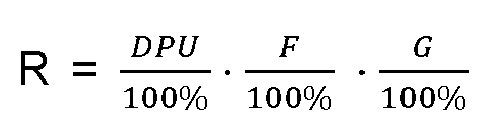
- Robot de nettoyage (1) selon la revendication précédente, dans lequel une valeur caractéristique de configuration K, qui est définie par la formule


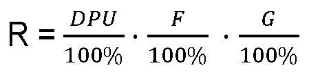
- Robot de nettoyage (1) selon l'une des revendications précédentes 4 à 13, caractérisé en ce que le robot de nettoyage (1) présente une forme en D vu de dessus.
- Robot de nettoyage (1) selon l'une des revendications précédentes 4 à 14, caractérisé en ce que le robot de nettoyage (1) comprend une interface pour une transmission de données sans fil.
Applications Claiming Priority (1)
| Application Number | Priority Date | Filing Date | Title |
|---|---|---|---|
| DE102021200757.0A DE102021200757A1 (de) | 2021-01-28 | 2021-01-28 | Verfahren für ein Reinigen mit einem Reinigungsroboter und Reinigungsroboter |
Publications (3)
| Publication Number | Publication Date |
|---|---|
| EP4039150A1 EP4039150A1 (fr) | 2022-08-10 |
| EP4039150C0 EP4039150C0 (fr) | 2024-11-20 |
| EP4039150B1 true EP4039150B1 (fr) | 2024-11-20 |
Family
ID=79316907
Family Applications (1)
| Application Number | Title | Priority Date | Filing Date |
|---|---|---|---|
| EP22150881.5A Active EP4039150B1 (fr) | 2021-01-28 | 2022-01-11 | Procédé de nettoyage à l'aide d'un robot nettoyeur et robot nettoyeur |
Country Status (3)
| Country | Link |
|---|---|
| US (1) | US20220233043A1 (fr) |
| EP (1) | EP4039150B1 (fr) |
| DE (1) | DE102021200757A1 (fr) |
Families Citing this family (3)
| Publication number | Priority date | Publication date | Assignee | Title |
|---|---|---|---|---|
| CA2917900C (fr) * | 2009-03-13 | 2019-01-08 | Omachron Intellectual Property Inc. | Appareil de nettoyage de surface portable |
| CN117184353B (zh) * | 2023-09-25 | 2024-05-24 | 江苏云洲智能科技有限公司 | 一种用于船舶除锈的爬壁小车 |
| WO2025233654A1 (fr) * | 2024-05-06 | 2025-11-13 | Abu Dhabi Gas Development Company Limited | Robot d'aspiration de soufre |
Family Cites Families (9)
| Publication number | Priority date | Publication date | Assignee | Title |
|---|---|---|---|---|
| JP3904236B2 (ja) * | 1995-11-24 | 2007-04-11 | コーニンクレッカ フィリップス エレクトロニクス エヌ ヴィ | 臭気フィルタを有する真空掃除機 |
| KR101247933B1 (ko) | 2005-02-18 | 2013-03-26 | 아이로보트 코퍼레이션 | 습식 및 건식 청소를 위한 자동 표면 청소 로봇 |
| EP1913856B1 (fr) | 2006-10-20 | 2011-07-27 | Wessel-Werk GmbH | Appareil compact pour le nettoyage autonome par aspiration de revêtements de sol |
| DE202007003807U1 (de) | 2007-02-24 | 2007-06-06 | Wessel-Werk Gmbh & Co. Kg | Kompaktes Saugreinigungsgerät |
| AT10154U1 (de) * | 2007-08-20 | 2008-10-15 | Infrasport Ag | Roboter |
| US9233472B2 (en) * | 2013-01-18 | 2016-01-12 | Irobot Corporation | Mobile robot providing environmental mapping for household environmental control |
| KR20160058594A (ko) * | 2014-11-17 | 2016-05-25 | 삼성전자주식회사 | 로봇 청소기, 단말장치 및 그 제어 방법 |
| KR102683536B1 (ko) * | 2019-03-28 | 2024-07-11 | 삼성전자주식회사 | 청소 로봇 및 그 제어방법, 청소 로봇 충전 시스템 |
| US20220233040A1 (en) * | 2021-01-26 | 2022-07-28 | Xiwang Qi | Dual Function Robotic Cleaning Device |
-
2021
- 2021-01-28 DE DE102021200757.0A patent/DE102021200757A1/de active Pending
-
2022
- 2022-01-11 EP EP22150881.5A patent/EP4039150B1/fr active Active
- 2022-01-14 US US17/576,474 patent/US20220233043A1/en not_active Abandoned
Also Published As
| Publication number | Publication date |
|---|---|
| US20220233043A1 (en) | 2022-07-28 |
| DE102021200757A1 (de) | 2022-07-28 |
| EP4039150A1 (fr) | 2022-08-10 |
| EP4039150C0 (fr) | 2024-11-20 |
Similar Documents
| Publication | Publication Date | Title |
|---|---|---|
| EP4039150B1 (fr) | Procédé de nettoyage à l'aide d'un robot nettoyeur et robot nettoyeur | |
| EP3047783B1 (fr) | Robot aspirateur | |
| DE69512414T2 (de) | Automatische maschine und vorrichtung zur bodenentstaubung | |
| EP2982285B1 (fr) | Appareil de nettoyage de sol destine au nettoyage sec et humide et procede de fonctionnement d'un appareil de nettoyage de sol automobile | |
| DE69224666T2 (de) | Teppichreinigungsmaschine für teilchenbeseitigung | |
| EP3047771B1 (fr) | Robot aspirateur | |
| EP3454715B1 (fr) | Systeme et procede de nettoyage d'un sol avec un robot de nettoyage | |
| EP3733037B1 (fr) | Système comprenant un appareil de traitement du sol guidé à la main, un appareil de traitement du sol à fonctionnement entièrement automatique et un dispositif de calcul | |
| EP1098587A1 (fr) | Robot menager pour aspiration automatique de la poussiere sur des sols | |
| EP3409165B1 (fr) | Dispositif de support sur un robot de nettoyage | |
| EP3243418B1 (fr) | Système et procédé de nettoyage d'un plancher à l'aide d'un robot de nettoyage | |
| EP3409168A1 (fr) | Module de nettoyage d'angle pour robots de nettoyage modulaires | |
| EP3047781A1 (fr) | Aspirateur-traîneau à activation autonome, procédé d'aspiration de poussières et utilisation d'un aspirateur-traîneau utilisable à activation autonome | |
| DE102023107579A1 (de) | Minimierung der lachenbildung für autonomen nassreinigungsroboter | |
| EP3047772B1 (fr) | Robot aspirateur | |
| DE102017208960A1 (de) | Staubsauger mit einem motorisch betriebenen Dichtmittel | |
| DE102018116225A1 (de) | Reinigungsgerät | |
| WO2022152736A1 (fr) | Procédé de traitement autonome de surfaces de sol | |
| DE102007014548A1 (de) | Verfahrbares Haushalts-Bodenfeuchtreinigungsgerät | |
| DE20116069U1 (de) | Autonomer, von räumlichem Erinnerungsvermögen freier, selbstfahrender und selbststeuernder Reinigungsroboter | |
| DE102018212166B4 (de) | Automatische Reinigung einer Bodenfläche | |
| EP4461190B1 (fr) | Procédé et dispositif d'essuyage d'une accumulation de liquide | |
| DE102024206119B3 (de) | Verfahren zum Reinigen einer Seitenbürste | |
| DE202011000433U1 (de) | Nasssauger und Saugerkopf für einen Nasssauger | |
| DE102022200465A1 (de) | Verfahren zum Betrieb eines mobilen, selbstfahrenden Geräts |
Legal Events
| Date | Code | Title | Description |
|---|---|---|---|
| PUAI | Public reference made under article 153(3) epc to a published international application that has entered the european phase |
Free format text: ORIGINAL CODE: 0009012 |
|
| STAA | Information on the status of an ep patent application or granted ep patent |
Free format text: STATUS: THE APPLICATION HAS BEEN PUBLISHED |
|
| AK | Designated contracting states |
Kind code of ref document: A1 Designated state(s): AL AT BE BG CH CY CZ DE DK EE ES FI FR GB GR HR HU IE IS IT LI LT LU LV MC MK MT NL NO PL PT RO RS SE SI SK SM TR |
|
| STAA | Information on the status of an ep patent application or granted ep patent |
Free format text: STATUS: REQUEST FOR EXAMINATION WAS MADE |
|
| 17P | Request for examination filed |
Effective date: 20221017 |
|
| RBV | Designated contracting states (corrected) |
Designated state(s): AL AT BE BG CH CY CZ DE DK EE ES FI FR GB GR HR HU IE IS IT LI LT LU LV MC MK MT NL NO PL PT RO RS SE SI SK SM TR |
|
| GRAP | Despatch of communication of intention to grant a patent |
Free format text: ORIGINAL CODE: EPIDOSNIGR1 |
|
| STAA | Information on the status of an ep patent application or granted ep patent |
Free format text: STATUS: GRANT OF PATENT IS INTENDED |
|
| INTG | Intention to grant announced |
Effective date: 20240321 |
|
| RIN1 | Information on inventor provided before grant (corrected) |
Inventor name: HAYN, HENNING Inventor name: MOSEBACH, ANDREJ |
|
| GRAJ | Information related to disapproval of communication of intention to grant by the applicant or resumption of examination proceedings by the epo deleted |
Free format text: ORIGINAL CODE: EPIDOSDIGR1 |
|
| STAA | Information on the status of an ep patent application or granted ep patent |
Free format text: STATUS: REQUEST FOR EXAMINATION WAS MADE |
|
| INTC | Intention to grant announced (deleted) | ||
| GRAP | Despatch of communication of intention to grant a patent |
Free format text: ORIGINAL CODE: EPIDOSNIGR1 |
|
| STAA | Information on the status of an ep patent application or granted ep patent |
Free format text: STATUS: GRANT OF PATENT IS INTENDED |
|
| INTG | Intention to grant announced |
Effective date: 20240808 |
|
| GRAS | Grant fee paid |
Free format text: ORIGINAL CODE: EPIDOSNIGR3 |
|
| GRAA | (expected) grant |
Free format text: ORIGINAL CODE: 0009210 |
|
| STAA | Information on the status of an ep patent application or granted ep patent |
Free format text: STATUS: THE PATENT HAS BEEN GRANTED |
|
| AK | Designated contracting states |
Kind code of ref document: B1 Designated state(s): AL AT BE BG CH CY CZ DE DK EE ES FI FR GB GR HR HU IE IS IT LI LT LU LV MC MK MT NL NO PL PT RO RS SE SI SK SM TR |
|
| REG | Reference to a national code |
Ref country code: GB Ref legal event code: FG4D Free format text: NOT ENGLISH |
|
| REG | Reference to a national code |
Ref country code: CH Ref legal event code: EP |
|
| REG | Reference to a national code |
Ref country code: DE Ref legal event code: R096 Ref document number: 502022002136 Country of ref document: DE |
|
| REG | Reference to a national code |
Ref country code: IE Ref legal event code: FG4D Free format text: LANGUAGE OF EP DOCUMENT: GERMAN |
|
| U01 | Request for unitary effect filed |
Effective date: 20241211 |
|
| U07 | Unitary effect registered |
Designated state(s): AT BE BG DE DK EE FI FR IT LT LU LV MT NL PT RO SE SI Effective date: 20241220 |
|
| U20 | Renewal fee for the european patent with unitary effect paid |
Year of fee payment: 4 Effective date: 20250220 |
|
| PG25 | Lapsed in a contracting state [announced via postgrant information from national office to epo] |
Ref country code: IS Free format text: LAPSE BECAUSE OF FAILURE TO SUBMIT A TRANSLATION OF THE DESCRIPTION OR TO PAY THE FEE WITHIN THE PRESCRIBED TIME-LIMIT Effective date: 20250320 Ref country code: HR Free format text: LAPSE BECAUSE OF FAILURE TO SUBMIT A TRANSLATION OF THE DESCRIPTION OR TO PAY THE FEE WITHIN THE PRESCRIBED TIME-LIMIT Effective date: 20241120 |
|
| PG25 | Lapsed in a contracting state [announced via postgrant information from national office to epo] |
Ref country code: ES Free format text: LAPSE BECAUSE OF FAILURE TO SUBMIT A TRANSLATION OF THE DESCRIPTION OR TO PAY THE FEE WITHIN THE PRESCRIBED TIME-LIMIT Effective date: 20241120 |
|
| PG25 | Lapsed in a contracting state [announced via postgrant information from national office to epo] |
Ref country code: NO Free format text: LAPSE BECAUSE OF FAILURE TO SUBMIT A TRANSLATION OF THE DESCRIPTION OR TO PAY THE FEE WITHIN THE PRESCRIBED TIME-LIMIT Effective date: 20250220 |
|
| PG25 | Lapsed in a contracting state [announced via postgrant information from national office to epo] |
Ref country code: GR Free format text: LAPSE BECAUSE OF FAILURE TO SUBMIT A TRANSLATION OF THE DESCRIPTION OR TO PAY THE FEE WITHIN THE PRESCRIBED TIME-LIMIT Effective date: 20250221 |
|
| PG25 | Lapsed in a contracting state [announced via postgrant information from national office to epo] |
Ref country code: PL Free format text: LAPSE BECAUSE OF FAILURE TO SUBMIT A TRANSLATION OF THE DESCRIPTION OR TO PAY THE FEE WITHIN THE PRESCRIBED TIME-LIMIT Effective date: 20241120 |
|
| PG25 | Lapsed in a contracting state [announced via postgrant information from national office to epo] |
Ref country code: RS Free format text: LAPSE BECAUSE OF FAILURE TO SUBMIT A TRANSLATION OF THE DESCRIPTION OR TO PAY THE FEE WITHIN THE PRESCRIBED TIME-LIMIT Effective date: 20250220 |
|
| PG25 | Lapsed in a contracting state [announced via postgrant information from national office to epo] |
Ref country code: SM Free format text: LAPSE BECAUSE OF FAILURE TO SUBMIT A TRANSLATION OF THE DESCRIPTION OR TO PAY THE FEE WITHIN THE PRESCRIBED TIME-LIMIT Effective date: 20241120 |
|
| PG25 | Lapsed in a contracting state [announced via postgrant information from national office to epo] |
Ref country code: SK Free format text: LAPSE BECAUSE OF FAILURE TO SUBMIT A TRANSLATION OF THE DESCRIPTION OR TO PAY THE FEE WITHIN THE PRESCRIBED TIME-LIMIT Effective date: 20241120 |
|
| PG25 | Lapsed in a contracting state [announced via postgrant information from national office to epo] |
Ref country code: CZ Free format text: LAPSE BECAUSE OF FAILURE TO SUBMIT A TRANSLATION OF THE DESCRIPTION OR TO PAY THE FEE WITHIN THE PRESCRIBED TIME-LIMIT Effective date: 20241120 |
|
| REG | Reference to a national code |
Ref country code: CH Ref legal event code: PL |
|
| PG25 | Lapsed in a contracting state [announced via postgrant information from national office to epo] |
Ref country code: MC Free format text: LAPSE BECAUSE OF FAILURE TO SUBMIT A TRANSLATION OF THE DESCRIPTION OR TO PAY THE FEE WITHIN THE PRESCRIBED TIME-LIMIT Effective date: 20241120 |
|
| PLBE | No opposition filed within time limit |
Free format text: ORIGINAL CODE: 0009261 |
|
| STAA | Information on the status of an ep patent application or granted ep patent |
Free format text: STATUS: NO OPPOSITION FILED WITHIN TIME LIMIT |
|
| PG25 | Lapsed in a contracting state [announced via postgrant information from national office to epo] |
Ref country code: CH Free format text: LAPSE BECAUSE OF NON-PAYMENT OF DUE FEES Effective date: 20250131 |
|
| 26N | No opposition filed |
Effective date: 20250821 |
|
| PG25 | Lapsed in a contracting state [announced via postgrant information from national office to epo] |
Ref country code: IE Free format text: LAPSE BECAUSE OF NON-PAYMENT OF DUE FEES Effective date: 20250111 |
|
| U20 | Renewal fee for the european patent with unitary effect paid |
Year of fee payment: 5 Effective date: 20260128 |
|
| PGFP | Annual fee paid to national office [announced via postgrant information from national office to epo] |
Ref country code: GB Payment date: 20260122 Year of fee payment: 5 |