EP4039459A1 - Structure stratifiée, câble et tube - Google Patents
Structure stratifiée, câble et tube Download PDFInfo
- Publication number
- EP4039459A1 EP4039459A1 EP22155577.4A EP22155577A EP4039459A1 EP 4039459 A1 EP4039459 A1 EP 4039459A1 EP 22155577 A EP22155577 A EP 22155577A EP 4039459 A1 EP4039459 A1 EP 4039459A1
- Authority
- EP
- European Patent Office
- Prior art keywords
- fine particles
- layer
- laminate structure
- light
- mass
- Prior art date
- Legal status (The legal status is an assumption and is not a legal conclusion. Google has not performed a legal analysis and makes no representation as to the accuracy of the status listed.)
- Pending
Links
Images






Classifications
-
- H—ELECTRICITY
- H01—ELECTRIC ELEMENTS
- H01B—CABLES; CONDUCTORS; INSULATORS; SELECTION OF MATERIALS FOR THEIR CONDUCTIVE, INSULATING OR DIELECTRIC PROPERTIES
- H01B7/00—Insulated conductors or cables characterised by their form
- H01B7/17—Protection against damage caused by external factors, e.g. sheaths or armouring
-
- H—ELECTRICITY
- H01—ELECTRIC ELEMENTS
- H01B—CABLES; CONDUCTORS; INSULATORS; SELECTION OF MATERIALS FOR THEIR CONDUCTIVE, INSULATING OR DIELECTRIC PROPERTIES
- H01B7/00—Insulated conductors or cables characterised by their form
- H01B7/02—Disposition of insulation
- H01B7/0208—Cables with several layers of insulating material
- H01B7/0225—Three or more layers
-
- C—CHEMISTRY; METALLURGY
- C08—ORGANIC MACROMOLECULAR COMPOUNDS; THEIR PREPARATION OR CHEMICAL WORKING-UP; COMPOSITIONS BASED THEREON
- C08J—WORKING-UP; GENERAL PROCESSES OF COMPOUNDING; AFTER-TREATMENT NOT COVERED BY SUBCLASSES C08B, C08C, C08F, C08G or C08H
- C08J7/00—Chemical treatment or coating of shaped articles made of macromolecular substances
- C08J7/04—Coating
- C08J7/0427—Coating with only one layer of a composition containing a polymer binder
-
- B—PERFORMING OPERATIONS; TRANSPORTING
- B32—LAYERED PRODUCTS
- B32B—LAYERED PRODUCTS, i.e. PRODUCTS BUILT-UP OF STRATA OF FLAT OR NON-FLAT, e.g. CELLULAR OR HONEYCOMB, FORM
- B32B1/00—Layered products having a non-planar shape
- B32B1/08—Tubular products
-
- A—HUMAN NECESSITIES
- A61—MEDICAL OR VETERINARY SCIENCE; HYGIENE
- A61B—DIAGNOSIS; SURGERY; IDENTIFICATION
- A61B8/00—Diagnosis using ultrasonic, sonic or infrasonic waves
- A61B8/44—Constructional features of the ultrasonic, sonic or infrasonic diagnostic device
- A61B8/4444—Constructional features of the ultrasonic, sonic or infrasonic diagnostic device related to the probe
-
- A—HUMAN NECESSITIES
- A61—MEDICAL OR VETERINARY SCIENCE; HYGIENE
- A61B—DIAGNOSIS; SURGERY; IDENTIFICATION
- A61B8/00—Diagnosis using ultrasonic, sonic or infrasonic waves
- A61B8/56—Details of data transmission or power supply
-
- A—HUMAN NECESSITIES
- A61—MEDICAL OR VETERINARY SCIENCE; HYGIENE
- A61L—METHODS OR APPARATUS FOR STERILISING MATERIALS OR OBJECTS IN GENERAL; DISINFECTION, STERILISATION OR DEODORISATION OF AIR; CHEMICAL ASPECTS OF BANDAGES, DRESSINGS, ABSORBENT PADS OR SURGICAL ARTICLES; MATERIALS FOR BANDAGES, DRESSINGS, ABSORBENT PADS OR SURGICAL ARTICLES
- A61L29/00—Materials for catheters, medical tubing, cannulae, or endoscopes or for coating catheters
- A61L29/04—Macromolecular materials
- A61L29/06—Macromolecular materials obtained otherwise than by reactions only involving carbon-to-carbon unsaturated bonds
-
- A—HUMAN NECESSITIES
- A61—MEDICAL OR VETERINARY SCIENCE; HYGIENE
- A61L—METHODS OR APPARATUS FOR STERILISING MATERIALS OR OBJECTS IN GENERAL; DISINFECTION, STERILISATION OR DEODORISATION OF AIR; CHEMICAL ASPECTS OF BANDAGES, DRESSINGS, ABSORBENT PADS OR SURGICAL ARTICLES; MATERIALS FOR BANDAGES, DRESSINGS, ABSORBENT PADS OR SURGICAL ARTICLES
- A61L29/00—Materials for catheters, medical tubing, cannulae, or endoscopes or for coating catheters
- A61L29/08—Materials for coatings
- A61L29/085—Macromolecular materials
-
- A—HUMAN NECESSITIES
- A61—MEDICAL OR VETERINARY SCIENCE; HYGIENE
- A61L—METHODS OR APPARATUS FOR STERILISING MATERIALS OR OBJECTS IN GENERAL; DISINFECTION, STERILISATION OR DEODORISATION OF AIR; CHEMICAL ASPECTS OF BANDAGES, DRESSINGS, ABSORBENT PADS OR SURGICAL ARTICLES; MATERIALS FOR BANDAGES, DRESSINGS, ABSORBENT PADS OR SURGICAL ARTICLES
- A61L29/00—Materials for catheters, medical tubing, cannulae, or endoscopes or for coating catheters
- A61L29/12—Composite materials, i.e. containing one material dispersed in a matrix of the same or different material
- A61L29/126—Composite materials, i.e. containing one material dispersed in a matrix of the same or different material having a macromolecular matrix
-
- B—PERFORMING OPERATIONS; TRANSPORTING
- B32—LAYERED PRODUCTS
- B32B—LAYERED PRODUCTS, i.e. PRODUCTS BUILT-UP OF STRATA OF FLAT OR NON-FLAT, e.g. CELLULAR OR HONEYCOMB, FORM
- B32B25/00—Layered products comprising a layer of natural or synthetic rubber
- B32B25/02—Layered products comprising a layer of natural or synthetic rubber with fibres or particles being present as additives in the layer
-
- B—PERFORMING OPERATIONS; TRANSPORTING
- B32—LAYERED PRODUCTS
- B32B—LAYERED PRODUCTS, i.e. PRODUCTS BUILT-UP OF STRATA OF FLAT OR NON-FLAT, e.g. CELLULAR OR HONEYCOMB, FORM
- B32B25/00—Layered products comprising a layer of natural or synthetic rubber
- B32B25/04—Layered products comprising a layer of natural or synthetic rubber comprising rubber as the main or only constituent of a layer, which is next to another layer of the same or of a different material
- B32B25/042—Layered products comprising a layer of natural or synthetic rubber comprising rubber as the main or only constituent of a layer, which is next to another layer of the same or of a different material of natural rubber or synthetic rubber
-
- B—PERFORMING OPERATIONS; TRANSPORTING
- B32—LAYERED PRODUCTS
- B32B—LAYERED PRODUCTS, i.e. PRODUCTS BUILT-UP OF STRATA OF FLAT OR NON-FLAT, e.g. CELLULAR OR HONEYCOMB, FORM
- B32B25/00—Layered products comprising a layer of natural or synthetic rubber
- B32B25/04—Layered products comprising a layer of natural or synthetic rubber comprising rubber as the main or only constituent of a layer, which is next to another layer of the same or of a different material
- B32B25/08—Layered products comprising a layer of natural or synthetic rubber comprising rubber as the main or only constituent of a layer, which is next to another layer of the same or of a different material of synthetic resin
-
- B—PERFORMING OPERATIONS; TRANSPORTING
- B32—LAYERED PRODUCTS
- B32B—LAYERED PRODUCTS, i.e. PRODUCTS BUILT-UP OF STRATA OF FLAT OR NON-FLAT, e.g. CELLULAR OR HONEYCOMB, FORM
- B32B25/00—Layered products comprising a layer of natural or synthetic rubber
- B32B25/20—Layered products comprising a layer of natural or synthetic rubber comprising silicone rubber
-
- B—PERFORMING OPERATIONS; TRANSPORTING
- B32—LAYERED PRODUCTS
- B32B—LAYERED PRODUCTS, i.e. PRODUCTS BUILT-UP OF STRATA OF FLAT OR NON-FLAT, e.g. CELLULAR OR HONEYCOMB, FORM
- B32B27/00—Layered products comprising a layer of synthetic resin
- B32B27/18—Layered products comprising a layer of synthetic resin characterised by the use of special additives
-
- B—PERFORMING OPERATIONS; TRANSPORTING
- B32—LAYERED PRODUCTS
- B32B—LAYERED PRODUCTS, i.e. PRODUCTS BUILT-UP OF STRATA OF FLAT OR NON-FLAT, e.g. CELLULAR OR HONEYCOMB, FORM
- B32B27/00—Layered products comprising a layer of synthetic resin
- B32B27/30—Layered products comprising a layer of synthetic resin comprising vinyl (co)polymers; comprising acrylic (co)polymers
- B32B27/304—Layered products comprising a layer of synthetic resin comprising vinyl (co)polymers; comprising acrylic (co)polymers comprising vinyl halide (co)polymers, e.g. PVC, PVDC, PVF, PVDF
-
- B—PERFORMING OPERATIONS; TRANSPORTING
- B32—LAYERED PRODUCTS
- B32B—LAYERED PRODUCTS, i.e. PRODUCTS BUILT-UP OF STRATA OF FLAT OR NON-FLAT, e.g. CELLULAR OR HONEYCOMB, FORM
- B32B27/00—Layered products comprising a layer of synthetic resin
- B32B27/32—Layered products comprising a layer of synthetic resin comprising polyolefins
-
- B—PERFORMING OPERATIONS; TRANSPORTING
- B32—LAYERED PRODUCTS
- B32B—LAYERED PRODUCTS, i.e. PRODUCTS BUILT-UP OF STRATA OF FLAT OR NON-FLAT, e.g. CELLULAR OR HONEYCOMB, FORM
- B32B27/00—Layered products comprising a layer of synthetic resin
- B32B27/32—Layered products comprising a layer of synthetic resin comprising polyolefins
- B32B27/322—Layered products comprising a layer of synthetic resin comprising polyolefins comprising halogenated polyolefins, e.g. PTFE
-
- B—PERFORMING OPERATIONS; TRANSPORTING
- B32—LAYERED PRODUCTS
- B32B—LAYERED PRODUCTS, i.e. PRODUCTS BUILT-UP OF STRATA OF FLAT OR NON-FLAT, e.g. CELLULAR OR HONEYCOMB, FORM
- B32B27/00—Layered products comprising a layer of synthetic resin
- B32B27/40—Layered products comprising a layer of synthetic resin comprising polyurethanes
-
- B—PERFORMING OPERATIONS; TRANSPORTING
- B32—LAYERED PRODUCTS
- B32B—LAYERED PRODUCTS, i.e. PRODUCTS BUILT-UP OF STRATA OF FLAT OR NON-FLAT, e.g. CELLULAR OR HONEYCOMB, FORM
- B32B3/00—Layered products comprising a layer with external or internal discontinuities or unevennesses, or a layer of non-planar shape; Layered products comprising a layer having particular features of form
- B32B3/26—Layered products comprising a layer with external or internal discontinuities or unevennesses, or a layer of non-planar shape; Layered products comprising a layer having particular features of form characterised by a particular shape of the outline of the cross-section of a continuous layer; characterised by a layer with cavities or internal voids ; characterised by an apertured layer
- B32B3/30—Layered products comprising a layer with external or internal discontinuities or unevennesses, or a layer of non-planar shape; Layered products comprising a layer having particular features of form characterised by a particular shape of the outline of the cross-section of a continuous layer; characterised by a layer with cavities or internal voids ; characterised by an apertured layer characterised by a layer formed with recesses or projections, e.g. hollows, grooves, protuberances, ribs
-
- B—PERFORMING OPERATIONS; TRANSPORTING
- B32—LAYERED PRODUCTS
- B32B—LAYERED PRODUCTS, i.e. PRODUCTS BUILT-UP OF STRATA OF FLAT OR NON-FLAT, e.g. CELLULAR OR HONEYCOMB, FORM
- B32B7/00—Layered products characterised by the relation between layers; Layered products characterised by the relative orientation of features between layers, or by the relative values of a measurable parameter between layers, i.e. products comprising layers having different physical, chemical or physicochemical properties; Layered products characterised by the interconnection of layers
- B32B7/02—Physical, chemical or physicochemical properties
- B32B7/023—Optical properties
-
- C—CHEMISTRY; METALLURGY
- C09—DYES; PAINTS; POLISHES; NATURAL RESINS; ADHESIVES; COMPOSITIONS NOT OTHERWISE PROVIDED FOR; APPLICATIONS OF MATERIALS NOT OTHERWISE PROVIDED FOR
- C09D—COATING COMPOSITIONS, e.g. PAINTS, VARNISHES OR LACQUERS; FILLING PASTES; CHEMICAL PAINT OR INK REMOVERS; INKS; CORRECTING FLUIDS; WOODSTAINS; PASTES OR SOLIDS FOR COLOURING OR PRINTING; USE OF MATERIALS THEREFOR
- C09D183/00—Coating compositions based on macromolecular compounds obtained by reactions forming in the main chain of the macromolecule a linkage containing silicon, with or without sulfur, nitrogen, oxygen, or carbon only; Coating compositions based on derivatives of such polymers
-
- C—CHEMISTRY; METALLURGY
- C09—DYES; PAINTS; POLISHES; NATURAL RESINS; ADHESIVES; COMPOSITIONS NOT OTHERWISE PROVIDED FOR; APPLICATIONS OF MATERIALS NOT OTHERWISE PROVIDED FOR
- C09D—COATING COMPOSITIONS, e.g. PAINTS, VARNISHES OR LACQUERS; FILLING PASTES; CHEMICAL PAINT OR INK REMOVERS; INKS; CORRECTING FLUIDS; WOODSTAINS; PASTES OR SOLIDS FOR COLOURING OR PRINTING; USE OF MATERIALS THEREFOR
- C09D183/00—Coating compositions based on macromolecular compounds obtained by reactions forming in the main chain of the macromolecule a linkage containing silicon, with or without sulfur, nitrogen, oxygen, or carbon only; Coating compositions based on derivatives of such polymers
- C09D183/04—Polysiloxanes
-
- C—CHEMISTRY; METALLURGY
- C09—DYES; PAINTS; POLISHES; NATURAL RESINS; ADHESIVES; COMPOSITIONS NOT OTHERWISE PROVIDED FOR; APPLICATIONS OF MATERIALS NOT OTHERWISE PROVIDED FOR
- C09D—COATING COMPOSITIONS, e.g. PAINTS, VARNISHES OR LACQUERS; FILLING PASTES; CHEMICAL PAINT OR INK REMOVERS; INKS; CORRECTING FLUIDS; WOODSTAINS; PASTES OR SOLIDS FOR COLOURING OR PRINTING; USE OF MATERIALS THEREFOR
- C09D5/00—Coating compositions, e.g. paints, varnishes or lacquers, characterised by their physical nature or the effects produced; Filling pastes
- C09D5/32—Radiation-absorbing paints
-
- C—CHEMISTRY; METALLURGY
- C09—DYES; PAINTS; POLISHES; NATURAL RESINS; ADHESIVES; COMPOSITIONS NOT OTHERWISE PROVIDED FOR; APPLICATIONS OF MATERIALS NOT OTHERWISE PROVIDED FOR
- C09D—COATING COMPOSITIONS, e.g. PAINTS, VARNISHES OR LACQUERS; FILLING PASTES; CHEMICAL PAINT OR INK REMOVERS; INKS; CORRECTING FLUIDS; WOODSTAINS; PASTES OR SOLIDS FOR COLOURING OR PRINTING; USE OF MATERIALS THEREFOR
- C09D7/00—Features of coating compositions, not provided for in group C09D5/00; Processes for incorporating ingredients in coating compositions
- C09D7/40—Additives
- C09D7/60—Additives non-macromolecular
- C09D7/61—Additives non-macromolecular inorganic
-
- C—CHEMISTRY; METALLURGY
- C09—DYES; PAINTS; POLISHES; NATURAL RESINS; ADHESIVES; COMPOSITIONS NOT OTHERWISE PROVIDED FOR; APPLICATIONS OF MATERIALS NOT OTHERWISE PROVIDED FOR
- C09D—COATING COMPOSITIONS, e.g. PAINTS, VARNISHES OR LACQUERS; FILLING PASTES; CHEMICAL PAINT OR INK REMOVERS; INKS; CORRECTING FLUIDS; WOODSTAINS; PASTES OR SOLIDS FOR COLOURING OR PRINTING; USE OF MATERIALS THEREFOR
- C09D7/00—Features of coating compositions, not provided for in group C09D5/00; Processes for incorporating ingredients in coating compositions
- C09D7/40—Additives
- C09D7/65—Additives macromolecular
-
- H—ELECTRICITY
- H01—ELECTRIC ELEMENTS
- H01B—CABLES; CONDUCTORS; INSULATORS; SELECTION OF MATERIALS FOR THEIR CONDUCTIVE, INSULATING OR DIELECTRIC PROPERTIES
- H01B1/00—Conductors or conductive bodies characterised by the conductive materials; Selection of materials as conductors
- H01B1/02—Conductors or conductive bodies characterised by the conductive materials; Selection of materials as conductors mainly consisting of metals or alloys
-
- H—ELECTRICITY
- H01—ELECTRIC ELEMENTS
- H01B—CABLES; CONDUCTORS; INSULATORS; SELECTION OF MATERIALS FOR THEIR CONDUCTIVE, INSULATING OR DIELECTRIC PROPERTIES
- H01B3/00—Insulators or insulating bodies characterised by the insulating materials; Selection of materials for their insulating or dielectric properties
- H01B3/18—Insulators or insulating bodies characterised by the insulating materials; Selection of materials for their insulating or dielectric properties mainly consisting of organic substances
- H01B3/30—Insulators or insulating bodies characterised by the insulating materials; Selection of materials for their insulating or dielectric properties mainly consisting of organic substances plastics; resins; waxes
- H01B3/46—Insulators or insulating bodies characterised by the insulating materials; Selection of materials for their insulating or dielectric properties mainly consisting of organic substances plastics; resins; waxes silicones
-
- H—ELECTRICITY
- H01—ELECTRIC ELEMENTS
- H01B—CABLES; CONDUCTORS; INSULATORS; SELECTION OF MATERIALS FOR THEIR CONDUCTIVE, INSULATING OR DIELECTRIC PROPERTIES
- H01B7/00—Insulated conductors or cables characterised by their form
- H01B7/02—Disposition of insulation
- H01B7/0208—Cables with several layers of insulating material
- H01B7/0216—Two layers
-
- A—HUMAN NECESSITIES
- A61—MEDICAL OR VETERINARY SCIENCE; HYGIENE
- A61B—DIAGNOSIS; SURGERY; IDENTIFICATION
- A61B2562/00—Details of sensors; Constructional details of sensor housings or probes; Accessories for sensors
- A61B2562/22—Arrangements of medical sensors with cables or leads; Connectors or couplings specifically adapted for medical sensors
- A61B2562/221—Arrangements of sensors with cables or leads, e.g. cable harnesses
- A61B2562/222—Electrical cables or leads therefor, e.g. coaxial cables or ribbon cables
-
- A—HUMAN NECESSITIES
- A61—MEDICAL OR VETERINARY SCIENCE; HYGIENE
- A61B—DIAGNOSIS; SURGERY; IDENTIFICATION
- A61B8/00—Diagnosis using ultrasonic, sonic or infrasonic waves
- A61B8/44—Constructional features of the ultrasonic, sonic or infrasonic diagnostic device
-
- B—PERFORMING OPERATIONS; TRANSPORTING
- B32—LAYERED PRODUCTS
- B32B—LAYERED PRODUCTS, i.e. PRODUCTS BUILT-UP OF STRATA OF FLAT OR NON-FLAT, e.g. CELLULAR OR HONEYCOMB, FORM
- B32B2250/00—Layers arrangement
- B32B2250/02—2 layers
-
- B—PERFORMING OPERATIONS; TRANSPORTING
- B32—LAYERED PRODUCTS
- B32B—LAYERED PRODUCTS, i.e. PRODUCTS BUILT-UP OF STRATA OF FLAT OR NON-FLAT, e.g. CELLULAR OR HONEYCOMB, FORM
- B32B2250/00—Layers arrangement
- B32B2250/24—All layers being polymeric
-
- B—PERFORMING OPERATIONS; TRANSPORTING
- B32—LAYERED PRODUCTS
- B32B—LAYERED PRODUCTS, i.e. PRODUCTS BUILT-UP OF STRATA OF FLAT OR NON-FLAT, e.g. CELLULAR OR HONEYCOMB, FORM
- B32B2255/00—Coating on the layer surface
- B32B2255/10—Coating on the layer surface on synthetic resin layer or on natural or synthetic rubber layer
-
- B—PERFORMING OPERATIONS; TRANSPORTING
- B32—LAYERED PRODUCTS
- B32B—LAYERED PRODUCTS, i.e. PRODUCTS BUILT-UP OF STRATA OF FLAT OR NON-FLAT, e.g. CELLULAR OR HONEYCOMB, FORM
- B32B2255/00—Coating on the layer surface
- B32B2255/26—Polymeric coating
-
- B—PERFORMING OPERATIONS; TRANSPORTING
- B32—LAYERED PRODUCTS
- B32B—LAYERED PRODUCTS, i.e. PRODUCTS BUILT-UP OF STRATA OF FLAT OR NON-FLAT, e.g. CELLULAR OR HONEYCOMB, FORM
- B32B2264/00—Composition or properties of particles which form a particulate layer or are present as additives
- B32B2264/10—Inorganic particles
- B32B2264/102—Oxide or hydroxide
- B32B2264/1021—Silica
-
- B—PERFORMING OPERATIONS; TRANSPORTING
- B32—LAYERED PRODUCTS
- B32B—LAYERED PRODUCTS, i.e. PRODUCTS BUILT-UP OF STRATA OF FLAT OR NON-FLAT, e.g. CELLULAR OR HONEYCOMB, FORM
- B32B2264/00—Composition or properties of particles which form a particulate layer or are present as additives
- B32B2264/10—Inorganic particles
- B32B2264/102—Oxide or hydroxide
- B32B2264/1022—Titania
-
- B—PERFORMING OPERATIONS; TRANSPORTING
- B32—LAYERED PRODUCTS
- B32B—LAYERED PRODUCTS, i.e. PRODUCTS BUILT-UP OF STRATA OF FLAT OR NON-FLAT, e.g. CELLULAR OR HONEYCOMB, FORM
- B32B2264/00—Composition or properties of particles which form a particulate layer or are present as additives
- B32B2264/12—Mixture of at least two particles made of different materials
-
- B—PERFORMING OPERATIONS; TRANSPORTING
- B32—LAYERED PRODUCTS
- B32B—LAYERED PRODUCTS, i.e. PRODUCTS BUILT-UP OF STRATA OF FLAT OR NON-FLAT, e.g. CELLULAR OR HONEYCOMB, FORM
- B32B2307/00—Properties of the layers or laminate
- B32B2307/10—Properties of the layers or laminate having particular acoustical properties
- B32B2307/102—Insulating
-
- B—PERFORMING OPERATIONS; TRANSPORTING
- B32—LAYERED PRODUCTS
- B32B—LAYERED PRODUCTS, i.e. PRODUCTS BUILT-UP OF STRATA OF FLAT OR NON-FLAT, e.g. CELLULAR OR HONEYCOMB, FORM
- B32B2307/00—Properties of the layers or laminate
- B32B2307/20—Properties of the layers or laminate having particular electrical or magnetic properties, e.g. piezoelectric
- B32B2307/206—Insulating
-
- B—PERFORMING OPERATIONS; TRANSPORTING
- B32—LAYERED PRODUCTS
- B32B—LAYERED PRODUCTS, i.e. PRODUCTS BUILT-UP OF STRATA OF FLAT OR NON-FLAT, e.g. CELLULAR OR HONEYCOMB, FORM
- B32B2307/00—Properties of the layers or laminate
- B32B2307/50—Properties of the layers or laminate having particular mechanical properties
- B32B2307/51—Elastic
-
- B—PERFORMING OPERATIONS; TRANSPORTING
- B32—LAYERED PRODUCTS
- B32B—LAYERED PRODUCTS, i.e. PRODUCTS BUILT-UP OF STRATA OF FLAT OR NON-FLAT, e.g. CELLULAR OR HONEYCOMB, FORM
- B32B2307/00—Properties of the layers or laminate
- B32B2307/50—Properties of the layers or laminate having particular mechanical properties
- B32B2307/538—Roughness
-
- B—PERFORMING OPERATIONS; TRANSPORTING
- B32—LAYERED PRODUCTS
- B32B—LAYERED PRODUCTS, i.e. PRODUCTS BUILT-UP OF STRATA OF FLAT OR NON-FLAT, e.g. CELLULAR OR HONEYCOMB, FORM
- B32B2307/00—Properties of the layers or laminate
- B32B2307/70—Other properties
- B32B2307/71—Resistive to light or to UV
-
- B—PERFORMING OPERATIONS; TRANSPORTING
- B32—LAYERED PRODUCTS
- B32B—LAYERED PRODUCTS, i.e. PRODUCTS BUILT-UP OF STRATA OF FLAT OR NON-FLAT, e.g. CELLULAR OR HONEYCOMB, FORM
- B32B2457/00—Electrical equipment
-
- B—PERFORMING OPERATIONS; TRANSPORTING
- B32—LAYERED PRODUCTS
- B32B—LAYERED PRODUCTS, i.e. PRODUCTS BUILT-UP OF STRATA OF FLAT OR NON-FLAT, e.g. CELLULAR OR HONEYCOMB, FORM
- B32B2457/00—Electrical equipment
- B32B2457/04—Insulators
-
- B—PERFORMING OPERATIONS; TRANSPORTING
- B32—LAYERED PRODUCTS
- B32B—LAYERED PRODUCTS, i.e. PRODUCTS BUILT-UP OF STRATA OF FLAT OR NON-FLAT, e.g. CELLULAR OR HONEYCOMB, FORM
- B32B2597/00—Tubular articles, e.g. hoses, pipes
-
- C—CHEMISTRY; METALLURGY
- C08—ORGANIC MACROMOLECULAR COMPOUNDS; THEIR PREPARATION OR CHEMICAL WORKING-UP; COMPOSITIONS BASED THEREON
- C08J—WORKING-UP; GENERAL PROCESSES OF COMPOUNDING; AFTER-TREATMENT NOT COVERED BY SUBCLASSES C08B, C08C, C08F, C08G or C08H
- C08J2383/00—Characterised by the use of macromolecular compounds obtained by reactions forming in the main chain of the macromolecule a linkage containing silicon with or without sulfur, nitrogen, oxygen, or carbon only; Derivatives of such polymers
- C08J2383/04—Polysiloxanes
-
- C—CHEMISTRY; METALLURGY
- C08—ORGANIC MACROMOLECULAR COMPOUNDS; THEIR PREPARATION OR CHEMICAL WORKING-UP; COMPOSITIONS BASED THEREON
- C08J—WORKING-UP; GENERAL PROCESSES OF COMPOUNDING; AFTER-TREATMENT NOT COVERED BY SUBCLASSES C08B, C08C, C08F, C08G or C08H
- C08J2483/00—Characterised by the use of macromolecular compounds obtained by reactions forming in the main chain of the macromolecule a linkage containing silicon with or without sulfur, nitrogen, oxygen, or carbon only; Derivatives of such polymers
- C08J2483/04—Polysiloxanes
-
- C—CHEMISTRY; METALLURGY
- C08—ORGANIC MACROMOLECULAR COMPOUNDS; THEIR PREPARATION OR CHEMICAL WORKING-UP; COMPOSITIONS BASED THEREON
- C08K—Use of inorganic or non-macromolecular organic substances as compounding ingredients
- C08K3/00—Use of inorganic substances as compounding ingredients
- C08K3/18—Oxygen-containing compounds, e.g. metal carbonyls
- C08K3/20—Oxides; Hydroxides
- C08K3/22—Oxides; Hydroxides of metals
- C08K2003/2237—Oxides; Hydroxides of metals of titanium
- C08K2003/2241—Titanium dioxide
-
- C—CHEMISTRY; METALLURGY
- C08—ORGANIC MACROMOLECULAR COMPOUNDS; THEIR PREPARATION OR CHEMICAL WORKING-UP; COMPOSITIONS BASED THEREON
- C08L—COMPOSITIONS OF MACROMOLECULAR COMPOUNDS
- C08L2205/00—Polymer mixtures characterised by other features
- C08L2205/02—Polymer mixtures characterised by other features containing two or more polymers of the same C08L -group
- C08L2205/025—Polymer mixtures characterised by other features containing two or more polymers of the same C08L -group containing two or more polymers of the same hierarchy C08L, and differing only in parameters such as density, comonomer content, molecular weight, structure
Definitions
- the present invention relates to a laminate structure, a cable and a tube.
- Patent Literature 1 a cable for medical devices made of silicone rubber including fine particles and with a layer that covers a sheath has been known (see Patent Literature 1).
- PVC polyvinyl chloride
- silicone rubber has advantages such as little discoloration over time, but it tends to have low surface slidability.
- the layer of the cable described in Patent Literature 1 is made of silicone rubber including fine particles
- the surface of the cable is formed with irregularities (i.e., unevenness, indentations) derived from fine particles. This uneven surface makes it possible to reduce a contact area when the layer is in contact with other parts, thereby increasing the slidability of the surface of the layer, i.e., the slidability of the cable.
- Patent Literature 1 JP6723489B
- the object of the present invention is to provide a laminate structure with silicone rubber as a base material, which is superior in resistance to UV-C light, and a cable and a tube with an insulator made of the laminate structure.
- a laminate structure comprising:
- another aspect of the present invention provides: a cable or tube comprising an insulator comprising the above laminate structure.
- the present invention it is possible to provide a laminate structure with silicone rubber as a base material, which is superior in resistance to UV-C light, and a cable and a tube with an insulator made of the laminate structure.
- FIG. 1 is a vertical cross-sectional view of a laminate structure 1 according to the first embodiment of the present invention.
- the laminate structure 1 is composed of a first layer 10 including silicone rubber as a base material (i.e., parent material), and a second layer 11 layered on the first layer 10.
- the second layer 11 includes silicone rubber as a base material 111, first fine particles 112 to give irregularities to a surface, and second fine particles 113 to shield UV-C light by absorption and/or scattering.
- the first fine particles 112 are made of a material including Si such as silicone resin and silica that are more resistant to UV-C light than silicone rubber. It is also preferable that an average particle size of the second fine particles 113 is smaller than an average particle size of the first fine particles 112.
- the average particle size of the second fine particles 113 is preferably 1/2 or less of the average particle size of the first fine particles 112, and more preferably 1/5 or less of the average particle size of the first fine particles 112. This allows the second fine particles 113 to be polarized around the first fine particle 112 and the second fine particles 113 to be selectively placed in areas where the first fine particles 112 are not present in an in-plane direction of the second layer 11.
- UV-C light is an ultraviolet light within a wavelength range of 200 to 280 nm.
- Silicone rubber which is the base material for the first layer 10 and the second layer 11, is a kind of silicone resins.
- the silicone rubber is more resistant to ultraviolet light (e.g., UV-A light, UV-B light) than polyvinyl chloride, which is commonly used as a material for cables and tubes to be used in medical applications.
- Silicone rubber also adds the first fine particle, 112, which contains Si, such as silicone resin particles (i.e., fine particles) and silica (silicon oxide) particles (i.e., fine particles), to create a surface that is uneven and irregular, thereby reducing the level of surface stickiness (i.e., tacking), and improving slidability (i.e., sliding properties). Therefore, the second layer 11 including the silicone rubber doped with the first fine particles 112 can be layered on the first layer 10 including the silicone rubber but free of the first fine particles 112 to cover the surface of the first layer 10, thereby reducing the surface stickiness of the silicone rubber and improving the slidability.
- Si such as silicone resin particles (i.e., fine particles) and silica (silicon oxide) particles (i.e., fine particles)
- a silicone rubber that does not include the first fine particles 112 should have a certain thickness to have a performance as a base material (e.g., the function to protect or accommodate other articles) compared to a silicone rubber that includes the first fine particles 112.
- a silicone rubber that includes the first fine particles 112. it is preferable to use the laminate structure 1 as an insulator for cables and tubes, and to form the first layer 10 by extrusion or the like with high productivity, and then laminate the second layer 11 on the first layer 10 by coating or the like.
- the laminate structure 1 may have various forms depending on its application. For example, when used as an insulator for cables and tubes, it is molded in a tubular form, and when used as high UV-resistant sheets for constant temperature greenhouse or UV-shield sheets (UV-shield curtains) to shield against UV leakage from sterilization rooms or the like.
- UV-shield sheets UV-shield curtains
- the second layer 11 includes the first fine particles 112, which create the irregularities on the surface. This results in a smaller contact area and higher slidability, when the second layer 11 comes into contact with a contactant, as compared to a flat surface.
- silicone rubber which is the base material 111 of the second layer 11
- an addition reaction type silicone rubber coating agent or a condensation reaction type silicone rubber coating agent can be used.
- the addition reaction type silicone rubber coating agent it is preferable to use the addition reaction type silicone rubber coating agent in order to ensure adhesion and wear resistance to the first layer 10 including the silicone rubber as the base material.
- a thickness of the second layer 11 is not less than 3 ⁇ m to obtain good slidability and predetermined wipes resistance (i.e., resistance to being wiped off) of the surface of the laminate structure 1 by the second layer 11.
- the second layer 11 may be laminated on both sides of the first layer 10.
- the upper limit of the thickness of the second layer 11 is not particularly limited, it is preferable to be not more than 100 ⁇ m from the viewpoint of productivity, high flexibility and high bending property.
- the first fine particle 112 is, for example, a silicone resin fine particle, a silica particle, or a mixture of these two kinds of particles.
- the first fine particle 112 preferably has a higher hardness than the base material 111 composed of silicone rubber (e.g., the first fine particle 112 has a Shore (durometer A) hardness of not lower than 1.1 times the hardness of the base material 111).
- Silicone resin with fewer reaction groups (e.g., methyl groups) than silicone rubber has a higher hardness than silicone rubber, and silica with no reaction group is more hardness. In terms of mass, silica is the largest, silicone resin is the second largest, and silicone rubber is the smallest.
- silica with high hardness is the most preferable material for the first fine particles 112, and silicone resin is the next preferable material. This is because when a contact causes pressure on the surface of the second layer 11, the harder the first fine particle 112 can reduce the deformation of the surface of the second layer 11. This will reduce the increase in contact area between the second layer 11 and the contactant and maintain the slidability.
- the first fine particle 112 composed of silica is easily precipitated in the silicone rubber coating agent as a base material in the manufacturing process of the second layer 11. It is difficult to disperse the first fine particles 112 in silicone rubber (the second layer 11) compared to the first fine particles 112 composed of the silicone resin. Therefore, from the viewpoint of improving the uniformity of dispersion in silicone rubber (the second layer 11), it is preferable to use the first fine particles 112 composed of silicone resin.
- the first fine particle 112 composed of silicone resin, to maintain the slidability when the second layer 11 comes into contact with the contactant and to achieve the uniformity of the dispersion of the first fine particles 112 in silicone rubber as the base material.
- the average particle size of the first fine particles 112 is e.g., 1 ⁇ m or more and 10 ⁇ m or less.
- the concentration (mass%) of the first fine particles 112 in the second layer 11 is e.g., 10 mass% or more and 60 mass% or less.
- the "average particle size" in the present application is measured by the laser diffraction scattering method.
- the first fine particle 112 is more resistant to UV-C light than the silicone rubber as the base material 111. This is because the bond energy between atoms in the molecular structure of silicone resin or silica, which is the material of the first fine particle 112, is higher than the bond energy between atoms in the molecular structure of silicone rubber.
- the binding energy of C-H bond which is often contained in silicone rubber, is smaller (approximately 4.27 eV) than the energy of UV-C light (approximately 6.2 eV), so that the C-H bond is cut by UV-C light irradiation.
- the binding energy of Si-O bond which is often contained in the silicone resin, is greater (approximately 6.52 eV) than the energy of UV-C light, so that the Si-O bond does not break due to exposure of UV-C light.
- the second fine particle 113 is composed of a material, which has the characteristics of shielding UV-C light by absorbing and/or scattering it, such as titanium oxide (TiO 2 ), carbon (C), zinc oxide (ZnO), and iron oxide (Fe 2 O 3 ). Since the second fine particles 113 shield UV-C light, it is possible to reduce the degradation caused by UV-C light in the base material 111, which is composed of silicone rubber. Titanium oxide as a material of the second fine particle 113 can be either anatase, rutile, or brookite, and can be a mixture of two or more of them. In addition, titanium oxide may be supplemented with niobium oxide to provide stability.
- the average particle size of the second fine particles 113 is smaller than the average particle size of the first fine particles 112.
- the second fine particle 113 can be present in a gap space between the first fine particles 112.
- the second fine particles 113 can be polarized around the first fine particle 112, and the second fine particles 113 can be selectively placed in regions where the first fine particle 112 is not present along the in-plane direction of the second layer 11.
- the second fine particles 113 can be more effectively polarized around the first fine particle 112.
- the lower limit of the average particle size of the second fine particles 113 is not particularly limited, but from the viewpoint of availability, it is preferable that the average particle size of the second fine particles 113 is 10 nm or more.
- the "average particle size" of the second fine particles 113 was measured by laser diffraction scattering method.
- the region in which the first fine particle 112 is not present when the second layer 11 is observed from the surface is a region that is less resistant to UV-C light, where only the base material 111 composed of silicone rubber is present.
- the inventors of the present application found that it is possible to effectively improve resistance to UV-C light by selectively placing the second fine particles 113 in this region and thereby shielding UV-C light.
- the first layer 10 preferably includes a second fine particle 102 to absorb UV-C light, as well as the second layer 11 including the second fine particle 113, so as reduce degradation caused by UV-C light transmitted through the second layer 11.
- the first layer 10 includes a base material 101 composed of silicone rubber and the second fine particles 102 distributed in the base material 101, as shown in FIG. 1 .
- a material of the base material 101 polyethylene, chlorinated polyethylene, chloroprene rubber, polyvinyl chloride (PVC), polyurethanes and the like can be used.
- silicone rubber and chloroprene rubber are preferable from a viewpoint of chemical resistance and heat resistance.
- the first layer 10 may be composed of an insulating material with the addition of common formulations such as various crosslinkers, crosslinking catalysts, anti-aging agents, plasticizers, lubricants, fillers, flame retardants, stabilizers, colorants, and the like. It is also possible to mix organic ultraviolet absorbers instead of the second fine particles 102, which is dispersed in the base material 101.
- the material of the second fine particle 102 may be the same as the material of the second fine particle 113, e.g., titanium oxide, carbon. However, it is preferable that the second fine particles 102 are evenly distributed in the base material 101 so that the resistance to UV-C light in the first layer 10 does not vary depending on the location. For this reason, the average particle size of the second fine particles 102 is not particularly limited, but it is preferable to be, e.g., 10 nm or more and 1 ⁇ m or less. Here, the "average particle size" of the second fine particles 102 was measured by laser diffraction scattering method.
- FIG. 2 is a graph showing preferred ranges of Ti concentration in the first layer 10 including TiO 2 fine particles 102 as the second fine particles and Ti concentration in the second layer 11 including TiO 2 fine particles 113 as the second fine particles.
- the Ti concentration in the first layer 10 is preferably 0.35 mass% or more and 3.0 mass% or less.
- TiO 2 fine particles 102 at a Ti concentration of 0.35 mass% or more in the first layer 10, it is possible to maintain the high elongation at break measured when the tensile test specified in "JIS K6251 (1994)" is performed after UV-C light is irradiated on the cable including the laminate structure 1 as insulators (sheath and its layer).
- the goal was set to achieve an elongation at break of 250% or more after exposure of UV-C light of 1404 J/cm 2 since the elongation at break is at least 250% when the UV-C light was not irradiated to the laminate structure 1 with the second layer 11 that does not include the TiO 2 fine particles 102 (See FIG.8B ).
- the goal was set to achieve an elongation at break of 150% or more even after exposure to UV-C light of 2808 J/cm 2 , since the elongation at break required for general rubber materials is at least 150%.
- the Ti concentration in the first layer 10 is preferably not greater than 3.0 mass%.
- the Ti concentration in the second layer 11 is preferably 1.0 mass% or more and 4.4 mass% or less.
- TiO 2 fine particles 113 at a Ti concentration of 1.0 mass% or more in the second layer 11, it is possible to suppress the formation of cracks, which may reach of the first layer 10, on the surface of the laminate structure 1, due to bending test equivalent to 45% to 50% tensile after exposure to UV-C light at 1404 J/cm 2 .
- the method of the bending test and observation of the presence of cracks will be described below.
- the second layer 11 when the second layer 11 includes TiO 2 fine particles 113 at a Ti concentration greater than 4.4 mass%, the surface roughness of the second layer 11 will be greater. As the surface roughness increases, dirt and bacteria are easily attached and difficult to be removed.
- the second layer 11 includes the first fine particle 112, such as silicone resin fine particles
- the Ti concentration in the second layer 11 is preferably not greater than 4.4 mass%.
- the concentration of TiO 2 fine particle 113 in the second layer 11 is preferably higher than the concentration of TiO 2 fine particle 102 in the first layer 10, i.e., the Ti concentration of the second layer 11 is preferably higher than the Ti concentration of the first layer 10.
- All Ti in the first layer 10 are contained in TiO 2 fine particles 102, and all Ti in the second layer 11 are contained in TiO 2 fine particles 113.
- the Ti concentration in the first layer 10 and the Ti concentration in the second layer 11 are determined as the mean values in a measuring area of 125 ⁇ m wide ⁇ 95 ⁇ m high using an energy dispersive X-ray analyzer (EDS) mounted on a scanning electron microscope (SEM).
- EDS energy dispersive X-ray analyzer
- SEM scanning electron microscope
- the second embodiment of the present invention is a cable or tube with an insulator composed of the laminate structure 1 in the first embodiment.
- the cable to be used as a medical ultrasonic probe cable is described below.
- silicone rubber which has superior heat resistance and chemical resistance, is used as the material for sheath in cables used for medical applications.
- silicone rubber has a problem of poor slidability. Therefore, when silicone rubber is used as the material for the sheath of the cable, the problems that the cable can easily be caught with other parts and that dust can easily get on the surface of the cable will occur.
- FIG. 3 shows a schematic diagram of the configuration of an ultrasonic probe cable 2 in the second embodiment of the present invention.
- an ultrasonic probe 32 is attached to one end of a cable 20 via a boot 31, which protects the one end, as shown in FIG. 3 .
- a connector 33 that connects to a main body of an ultrasonic imaging device is attached to the other end of the cable 20.
- FIG. 4A shows a radial cross-sectional view of the cable 20 of the ultrasonic probe cable 2.
- the cable 20 includes, for example, plural electric wires 21, typically coaxial cables, and a shield 22, such as a braided shield, to cover the plural electric wires 21.
- a sheath 23 is provided to cover the shield 22.
- the cable 20 includes a coating film (i.e., layer) 24 covering a circumference of the sheath 23 and adhering to the sheath 23.
- FIG. 4B shows a radial cross-sectional view of the ultrasonic probe cable 2 cut along a line A-A in FIG.3 .
- the boot 31 is installed over the coating film 24 over an adhesive layer 34 covering the coating film 24 as shown in FIG. 4B .
- the adhesive layer 34 is formed from, e.g., silicone adhesive or epoxy adhesive.
- the boot 31 may be formed from, e.g., PVC, silicone rubber, chloroprene rubber, etc., and the boot 31 preferably includes the second fine particles 102 or organic UV absorbers to shield UV-C light, similarly to the first layer 10.
- Th sheath 23 and the coating film 24 of the cable 20 are respectively composed of the first layer 10 and the second layer 11 of the laminate structure 1.
- the laminate structure 1 is used as the sheath 23 and the coating film 24.
- the coating film 24 composed of the second layer 11, which is superior in sliding property it is possible to suppress the ultrasonic probe cable 2 from being caught due the stickiness of the surface of the sheath 23.
- the thickness of the coating film 24 is 3 ⁇ m or more and 100 ⁇ m or less. The illustration of the second fine particles 102 in the sheath 23 and the first fine particles 112 and the second fine particles 113 in the coating film 24 are omitted.
- the following is an example of a method for manufacturing the ultrasonic probe cable 2 in the present embodiment. First, plural (e.g., 100 or more) of electric wires 31 are bundled together. The shield 22 is then formed to cover the bundle of the electric wires 21.
- the sheath 23 and the coating film 24 are formed.
- the sheath 23 is formed by extrusion molding using e.g., an extruder.
- the coating film 24 is formed by, e.g., dipping, spraying or rolling application method. In the dipping method, the ultrasonic probe cable 2 formed up to the sheath 23 is pulled up through a liquid coating material to form the coating film 24 on a surface of the sheath 23. This dipping method is superior to the spraying or rolling application methods in terms of uniformity of a film thickness of the coating film 24 to be formed.
- the liquid coating agent used in the dipping method is a liquid silicone rubber including the first fine particles 112 and the second fine particles 113 and contains a solvent such as n-heptane.
- a solvent such as n-heptane.
- FIGS. 5A to 5C are cross-sectional views of a medical tube in the second embodiment of the present invention.
- a medical tube 40a shown in FIG. 5A has an outer layer 42 on an outer surface 41a of a tube main body 41.
- a medical tube 40b shown in FIG. 5B has an inner layer 43 on an inner surface 41b of the tube main body 41.
- a medical tube 40c shown in FIG. 5C has an outer layer 42 and an inner layer 43 respectively on an outer surface 41a and an inner surface 41b of the tube main body 41.
- the tube in the present embodiment includes the tube main body 41, and the outer layer 42 covering the outer surface 41a of the tube main body 41 or the inner layer 43 covering the inner surface 41b of the tube main body 41, or alternatively, both the outer layer 42 and the inner layer 43.
- the tube main body 41 of the medical tubes 40a, 40b, and 40c is composed of the first layer 10 of the laminate structure 1, and the outer layer 42 and the inner layer 43 are respectively composed of the second layer 11 of the laminate structure 1.
- the tubes in the present embodiment have excellent slidability at the inner surface or the outer surface, for example, when devices are inserted into the tubes, such as catheters or other medical tubes, smooth insertion and removal of the devices can be achieved.
- the tubes in the present invention may be used as tube sets for endoscopic surgical instruments, tube sets for ultrasonic surgical instruments, blood analyzer tubes, tubes within oxygen concentrators, artificial dialysis blood circuits, artificial cardiopulmonary circuits (artificial heart-lung circuits), endotracheal tubes, and so on.
- the surface has excellent slidability because the second layer 11 includes the first fine particles 112, and the second fine particles 113 are polarized around the first fine particle 112, which makes the laminate structure 1 more resistant to UV-C light.
- the ultrasonic probe cable 2 and the medical tubes 40a, 40b, 40c, etc. in the second embodiment, because the laminate structure 1 is used as an insulator, the ultrasonic probe cable 2 and the medical tubes 40a, 40b, 40c, etc., have excellent surface slidability and are resistant to UV-C light.
- silicone rubber is used as the material for the base material 111 in the second layer 11 of the laminate structure 1.
- rubber components other than silicone rubber such as chloroprene rubber, instead of silicone rubber.
- samples A1 to A4 were prepared to verify the shielding effect of UV-C light in the second layer 11 of the laminate structure 1.
- a cable core was prepared by stranding two-hundreds coaxial cables each with a diameter of about 0.25 mm and covering the stranded cables with a braided wire.
- a sheath material was extruded at a speed of 5 m/min to cover an outer periphery of the cable core, and the sheath 23 with a thickness of 0.8 mm was formed as the first layer 10 of the laminate structure 1 (an outer diameter of the cable was about 8 mm).
- a commonly used PVC was used for the sheath material of the sample A1.
- a color batch including titanium oxide (a mixture of "KE-color-W” and “KE-174-U” made by Shin-Etsu Chemical Co., Ltd.) was used.
- the mixture was adjusted in such a manner that Ti concentration analyzed by an energy dispersive X-ray analyzer (EDS) mounted on a scanning electron microscope (SEM) (average value in the measuring area of 125 ⁇ m wide ⁇ 95 ⁇ m high) is 0.12 mass%.
- EDS energy dispersive X-ray analyzer
- SEM scanning electron microscope
- a material for forming the coating film 24 of the sample A3 was prepared.
- An addition reaction type silicone rubber coating agent (product name: SILMARK-TM, made by Shin-Etsu Chemical Co., Ltd.) was prepared as a rubber component as the base material 111.
- silicone resin fine particles with an average particle size of 5 ⁇ m (product name: X-52-1621, made by Shin-Etsu Chemical Co., Ltd.) were prepared.
- the sheath 23 was then immersed in the above coating solution using the dip coating method, and a coating composed of silicone rubber was formed on the sheath surface. After that, the coating was thoroughly dried and cured at a temperature of 150°C to form the coating film 24 with uneven surface.
- the thickness of the coating film 24 of the sample A3 thus obtained was 15 ⁇ m.
- the sample A3 was prepared by the above process.
- the material for forming the coating film 24 of the A4 sample was prepared.
- the rubber component as the base material 111 and the silicone resin fine particles as the first fine particles 112 were prepared similarly to the materials used for the coating film 24 of the A3 sample.
- titanium oxide (anatase-type TiO 2 ) fine particles with an average particle size of 250 nm were prepared.
- the concentration of titanium oxide fine particles as the second fine particles 113 in the coating film 24 was adjusted in such a manner that Ti concentration in the coating film 24 analyzed by an energy dispersive X-ray analyzer (EDS) mounted on a scanning electron microscope (SEM) (mean value in the measuring area of 125 ⁇ m wide ⁇ 95 ⁇ m high) is 0.6 mass%.
- the content of the first fine particles 112 in the coating film 24 was calculated assuming that the coating agent cures with little or no mass reduction (approximately equivalent to the compound mass ratio).
- the sample A4 was prepared by the above process.
- a tensile test was performed on the samples A1 to A4 before and after UV-C light exposure.
- the sheath 23 of each of the cable-like samples A1 to A4 (the sheath 23 covered with the coating film 24 in the samples A3 and A4) was cut along the length direction, the content in the sheath 23 was removed and the sheath 23 was opened.
- the opened sheath 23 was punched with dumbbell-shaped punch No.6 to form a dumbbell test piece (thickness of 0.8 mm).
- dumbbell test pieces made from the sheaths 23 of the samples A1, A2, A3, and A4 are samples B1, B2, B3, and B4, respectively.
- Table 1 below shows the compositions of the samples B1 to B4.
- Table 1 Sheath Coating film Parent material The second fine particle Parent material The first fine particle The second fine particle B1 PVC - None - - B2 Silicone rubber Anatase TiO 2 (Ti: 0.12 mass%) None - - B3 Silicone rubber Anatase TiO 2 (Ti: 0.12 mass%) Silicone rubber Average particle size: 5 ⁇ m Silicone resin None B4 Silicone rubber Anatase TiO 2 (Ti: 0.12 mass%) Silicone rubber Average particle size: 5 ⁇ m Silicone resin Anatase TiO 2 (Ti: 0.6 mass%)
- the tensile test is a test specified in "JIS K6251 (1994)" and was performed on the above samples B1 to B4 under the condition at an ambient temperature of 15 to 35°C, an ambient humidity of 28 to 65% under an atmospheric pressure.
- UV-C light irradiation was performed by a storage chamber with sterilization lamps (Storage chamber DM-5, lamps GL-10, available from Daishin Kogyo Co., Ltd.,) at a chamber temperature of 25 to 40°C, a chamber humidity of 28% to 65%, a chamber pressure of 1 atm (atmospheric pressure), a wavelength of 253.7 nm, an illuminance of 1.3 mW/cm 2 , and irradiation times of 100 hours and 200 hours.
- the illuminance meter was UVC-254A made by MK Scientific Inc..
- FIG. 6A shows the results of the tensile test of the sample B1.
- "unexposed” shows the sample B1 before being exposed to UV-C light
- “after” shows the sample B1 after being exposed to UV-C light irradiation for 200 hours.
- the strength magnitude of stress when the base member is broken
- the elongation are smaller than before exposure
- the sample B1 deteriorates (changes to break easier) with the exposure of UV-C light.
- the sample B1 was a gray PVC
- 100% elongation indicates that the length of the Dumbbell test piece has doubled from the original length.
- FIG. 6B shows the results of the tensile test of the sample B2.
- "unexposed” shows the sample B2 before being exposed to UV-C light
- “after” shows the sample B2 after being exposed to UV-C light irradiation for 200 hours.
- FIG. 6B it was confirmed that after exposure of UV-C light, the strength and the elongation are smaller than before exposure, and that the sample B2 deteriorates (alters) with the exposure of UV-C light.
- discoloration of the sample B2 (white) composed of silicone rubber due to exposure to UV-C light was not visually confirmed.
- silicone rubber is more affected by UV-C light than PVC.
- the sample B2 includes TiO 2 fine particles as the second fine particles that absorb UV-C light, but at a low level (Ti concentration in the sheath 23 is 0.12 mass%). It is therefore thought that the resistance to UV-C light had little effect. In addition, since the sample B2 does not have a coating film corresponding to the second layer 11, it is inferior in sliding property to the samples B3 and B4.
- FIG. 7A shows the results of the tensile test of the sample B3.
- "unexposed” shows the sample B3 before being exposed to UV-C light
- “after” shows the sample B3 after being exposed to UV-C light irradiation for 200 hours.
- FIG. 7A it was confirmed that after exposure of UV-C light, the strength and the elongation are smaller than before exposure, and that the sample B3 deteriorates with the exposure of UV-C light.
- discoloration of the sample B3 (white) due to exposure to UV-C light was not visually confirmed similarly to the sample B2.
- the coating film 24 of the sample B3 includes silicone resin fine particles as the first fine particle 112, which are resistant to UV-C light. It is therefore thought that the silicone rubber in the region where the silicone resin fine particles are not present deteriorated so that the clacks occurred.
- FIG. 7B shows the results of the tensile test of the sample B4.
- "unexposed” shows the sample B4 before being exposed to UV-C light
- “after” shows the sample B4 after being exposed to UV-C light irradiation for 200 hours.
- FIG. 7B it was confirmed that after exposure of UV-C light, the strength and the elongation are substantially the same before and after exposure, and that deterioration of the sample B4 due to the exposure of UV-C light was effectively suppressed.
- discoloration of the sample B4 (white) due to exposure to UV-C light was not visually confirmed similarly to the sample B2.
- titanium oxide fine particles which are the second fine particles in the coating film corresponding to the second layer 11, have shielded UV-C light and suppressed the degradation.
- FIG. 8A shows the relationship between the irradiation time of UV-C light and the stress at break of the substrate for the samples B1 to B4.
- FIG. 8B shows the relationship between the irradiation time of UV-C light and the elongation at break of the substrate for the samples B1 to B4.
- the sample B3 which does not include titanium oxide fine particles as second fine particles in the coating film corresponding to the second layer 11, has decreased in strength and elongation with increased irradiation time of UV-C light.
- the sample B4 including titanium oxide fine particles as the second fine particles in the coating film corresponding to the second layer 11 has no change in strength and elongation, even if the irradiation time of UV-C light increases.
- the sample B4 has a lower elongation before exposure of UV-C light than the sample B1, but the elongation after 200 hours of exposure of UV-C light is superior to the sample B1.
- Raman mapping analysis was performed to determine the distribution of the second fine particles 113 in the second layer 11 of the laminate structure 1.
- Raman mapping analysis Raman scattering measurements are performed while scanning the laser on the surface of the sample, and the information obtained from Raman scattering spectrum at each measurement point is mapped in two dimensions.
- the Raman mapping analysis was performed using the samples prior to UV-C light exposure.
- Tables 2 and 3 below show the measurement and mapping conditions for the Raman scattering measurements, respectively.
- the Raman scattering measurements were performed using the RAMANforce Standard VIS-NIR-HS made by Nanophoton Corporation.
- the Raman scattering measurements were conducted at an ambient temperature of 15 to 35°C, an ambient humidity of 25 to 65% under atmospheric pressure.
- Table 2 Experiment Excitation wavelength 532.06 nm ND filter 6.27% (200/255) Central wavenumber of 2450.00 cm - 1 the spectrometer Diffraction grating 300 gr/mm Slit width 50 ⁇ m Exposure time 1 s Number of accrual counts 1 Objective lens TU Plan Fluor 100x/ NA 0.90 Measurement mode XY Mapping Z track ON Measurement order Vertical Sample temperature 24.5°C (room temperature) Table 3 Mapping criteria Width of the mapping area 75 pixels Height of the mapping area 75 pixels Total number of pixels 5625 pixels Spectral length 1340 pixels Data size 7537500 pixels Pixel aspect ratio 1.000 Horizontal pixel size 300.0 nm Vertical pixel size 300.0 nm Measuring range (width) 22.5 ⁇ m Measuring range (height) 22.5 ⁇ m
- the mapping analysis for this example was performed on the surface of sheet-like silicone rubber layers (samples E1 to E4) as four types of the second layer 11.
- All samples E1 to E4 includes silicone rubber as the base material 111, silicone resin fine particles with an average particle size of approximately 2 ⁇ m as the first fine particles 112, titanium oxide fine particles, mainly including anatase-type TiO 2 fine particles with an average particle size of approximately 250 nm as the second fine particles 113.
- the content of the silicone resin fine particles in each of the samples E1 to E4 is 60 mass%.
- the content of silicone resin fine particles in each of the samples E1 to E4 was calculated based on the assumption that silicone rubber coating agent cures with little or no mass reduction (approximately equivalent to the compound mass ratio). Specifically, the mass of silicone resin fine particles is divided by the total mass of silicone resin fine particles, titanium oxide fine particles and silicone rubber.
- Table 4 below shows the silicone resin fine particles as the first fine particles 112 and the silicone resin concentration in each sample, and the average particle size of titanium oxide fine particles as the second fine particles 113 and the Ti concentration in each sample, in the samples E1 to E4.
- the Ti concentration in Table 4 was determined by the SEM-EDS (the average value in the measuring area of 125 ⁇ m wide by 95 ⁇ m high).
- the sample E1 is equivalent to the sample A4 (B4).
- the samples E1 to E4 differ in the amount of titanium oxide fine particles as the second fine particles 113.
- the Ti concentrations (as measured by SEM-EDS) of the samples E1, E2, E3, and E4 are 0. 6 mass%, 1.1 mass%, 1. 5 mass%, and 4.4 mass%, respectively.
- FIG. 9 shows an example of the Raman scattering spectrum collected at a point in the sample E1.
- the peak at approximately 640 cm -1 (e.g., 640 +/- 20 cm -1 ) (Hereinafter referred to as "the first peak") in the Raman scattering spectrum is a particularly strong peak in the scattering spectrum of titanium oxide fine particles (mainly including anatase-type TiO 2 fine particles), mainly derived from lattice vibration Eg of the anatase-type TiO 2 .
- the peak at 2915 +/- 33 cm -1 (Hereinafter referred to as "the second peak”) is a particularly strong peak in the scattering spectrum of the silicone resin, which is derived from the CH stretch of the silicone resin.
- titanium oxide fine particles mainly include rutile type TiO 2 fine particles
- a peak at approximately 445 cm -1 e.g., 445 +/- 45cm -1
- titanium oxide fine particles mainly include brookite-type TiO 2 fine particles
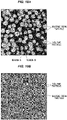
- FIGS. 10A , 11A , 12A , and 13A are respectively mapping images of the samples E1, E2, E3 and E4 obtained from the mapping analysis.
- the size of each mapping image (the mapping area) is 22. 5 ⁇ m ⁇ 22.5 ⁇ m.
- the mapping analysis was performed using the analysis software Raman Viewer Ver. 4.5.54 made by Nanophoton Corporation.
- the tint in the area representing the titanium oxide fine particles in FIGS. 10A , 11A , 12A , and 13A was set within the range of intensity of 20 to 3500 in such a manner that the tint should be darker as the intensity of the first peak increases. Further, the tint was set in such a manner that the titanium oxide fine particles should be present for the values within the range of 1760 to 3500.
- the tint in the area representing the silicone resin fine particles was set within the range of intensity of 400 to 3000 in such a manner that the tint should be darker as the intensity of the second peak increases.
- the tint was set in such a manner that the silicone resin fine particles should be present for the values within the range of 1700 to 3000.
- the titanium oxide fine particles are polarized around the silicone resin fine particle. It can be seen that the area without silicone resin fine particles (the area located between the silicone resin fine particles) is effectively filled. This is because the average particle size of the titanium oxide fine particles is smaller than the average particle size of the silicone resin fine particles (for example, 1/2 or less, preferably 1/5 or less). In addition, as the amount of titanium oxide fine particles increases, the proportion of the area occupied by titanium oxide fine particles in areas where silicone resin fine particles are not present increases, and when the Ti concentration is 1.5 mass% or more, almost all areas in the area where silicone resin fine particles are not present (areas that are less resistant to UV-C light) are occupied by titanium oxide fine particles.
- the second layer 11 includes a region where the intensity of the first peak in the area where silicone resin fine particles are present (a circular white region: Region A in FIGS. 10A , 11A , 12A and 13A ) is less than the intensity of the first peak in the area where silicone resin fine particles are not present (a region located between the silicone resin fine particles: Region B), since titanium oxide fine particles are present predominantly in the area where silicone resin fine particles are not present.
- a region located between the silicone resin fine particles a region located between the silicone resin fine particles
- FIGS. 10B , 11B , 12B , and 13B respectively, show bivaluated analysis images of the mapping images in FIGS. 10A , 11A , 12A , and 13A .
- This bivaluated analysis was performed by the "area ratio analysis" function of the above analysis software, Raman Viewer Ver. 4.5.54.
- an integral intensity of an integral range of 38.7cm -1 at the first peak was applied to calculation as a first peak intensity
- an integral intensity of an integral range of 35.2cm -1 at the second peak was applied to the calculation as a second peak intensity.
- the intensity calculation method for the bivaluated analysis is called "area calculation”.
- a ratio of the area of titanium oxide fine particles to the area other than titanium oxide fine particles is 6.4:93.6, 12.8:87.2, 22.7:77.3, and 35.2:64.8, respectively.
- the ratio of the area of titanium oxide fine particles to the total area of titanium oxide fine particles and silicone resin fine particles in the bivaluated analysis image conducted under the above conditions is 22.7% or more, almost all areas in the area where silicone resin fine particles are not present are occupied by titanium oxide fine particles, and that the second layer 11 has excellent resistance to UV-C light.
- the conditions for this second layer 11 to have excellent resistance to UV-C light would be satisfied even if the silicone resin fine particle as the first fine particle 112 is changed to another fine particle such as silica fine particle, or if the titanium oxide fine particle as the second fine particle 113 is changed to another fine particle such as carbon particle.
- the upper limit of the area of titanium oxide fine particles in the bivaluated analysis image is not less than 50% relative to the total area of titanium oxide fine particles and silicone resin fine particles.
- samples C1 to C11 were prepared to verify the resistance of the laminate structure 1 to UV-C light. All the samples C1 to C11 have the first layer 10 and the second layer 11, and the first layer 10 includes TiO 2 fine particles 102. Of the samples C1 to C11, the samples C1, C6, and C9 do not include TiO 2 fine particles 113 in the second layer 11 and were prepared using processes and materials similar to the sample A3 in Example 1. Also, the samples C2 to C5, C7, C8, C10, C11 include TiO 2 fine particles 113 in the second layer 11 (Ti concentration is within range from 1.1 mass % to 4.4 mass%) and were prepared using processes and materials similar to the sample A4 in Example 1.
- Table 5 below shows the composition of the sheath 23 and the coating film 24 of the samples C1 to C11.
- the thickness of the first layer 10 (sheath 23) was 0.8 mm, and the thickness of the second layer 11 (coating film 24) was 20 ⁇ m.
- UV-C light irradiation was performed by a storage chamber with sterilization lamps (Storage chamber DM-5, lamps GL-10, available from Daishin Kogyo Co., Ltd.) at chamber temperature of 25 to 40°C, chamber humidity of 28% to 65%, chamber pressure of 1 atm (atmospheric pressure), wavelength 253.7 nm, illuminance of 1.3 mW/cm 2 , and irradiation times of 200, 300, 400, and 600 hours.
- the illuminance meter was UVC-254A made by MK Scientific Inc..
- the bending test was also performed on the samples C1 to C11 at an ambient temperature of 15 to 35°C and an ambient humidity of 28 to 65% under atmospheric pressure.
- FIG. 14A shows a schematic diagram of the bending test.
- a sheath piece 50 was a part of the sheath 23 covered with the coating film 24, cut from each of the samples C1 to C11.
- a rectangular sheath piece 50 is cut from each of the samples C1 to C11 and wrapped around a lead wire (metal wire) 51 having a radius of 0.5 mm, then overlapping portions of the sheath piece 50 are fixed by pinching them from both sides (a fixing jig is not shown).
- cable-shape samples C1 to C11 of a length of 1 m were prepared and cut evenly along the cable length from ten locations to provide each piece with a size of 12 mm (in a cable circumferential direction) ⁇ 18 mm (in a cable longitudinal direction).
- the sheath piece 50 was wrapped around the lead wire 51 in such a manner that a cable longitudinal side would be located along a circumferential direction of the lead wire 51 and the second layer 11 would be located on an outer periphery side.
- FIG. 14B shows a cross-sectional view of the lead wire 51 and the sheath piece 50 wrapped around the lead wire 51. If the radius of the lead wire 51 is r and the thickness of sheath piece 50 is t, a longitudinal length of the sheath piece 50 at a neutral surface 50a at any angle ⁇ is (r+ t/2)• ⁇ , and a longitudinal length of an outer surface 50b of the sheath piece 50 is (r+t)• ⁇ , as shown in FIG. 14B .
- the bending test was performed on the sheath pieces 50 cut from the samples C1 to C11.
- the surface of the sheath piece 50 during the bending test (the second layer 11 was affected by an elongation equivalent to 45% to 50%) was observed with a 50X magnification ratio using an optical microscope (Digital Microscope VHX-1000 made by Keyence Corporation).
- FIGS. 15A and 15B show SEM observation images of a surface and a cross section of the sheath piece 50 cut from the sample C6 exposed to UV-C light at irradiation energy of 2808 J/cm 2 .
- FIGS. 16A and 16B show SEM observation images of the surface and a cross section of the sheath piece 50 cut from the sample C7 exposed to UV-C light with irradiation energy of 2808 J/cm 2 .
- cracks 52 that reach the second layer 11 to the first layer 10 were observed.
- FIGS. 15A and 16A were 100X SEM observation images
- FIGS. 15B and 16B are 1000X SEM observation images. They are the SEM observation image of the sheath piece 50 which was removed from the lead wire 51 after the bending test.
- the results of this bending test were used as one of the criteria for determining whether the laminate structure 1 is resistant to UV-C light.
- the sheath pieces 50 were taken from ten locations of each sample exposed to UV-C light.
- the bending test was conducted on each of ten sheath pieces 50, the number of sheath pieces 50 on which the cracks were observed was counted when observing the area of 1.5 mm ⁇ 4.5 mm using an optical microscope to obtain a 50X magnification ratio.
- the laminate structure 1 was determined to be resistant to UV-C light.
- FIG. 17 shows a representative observation image of the surface of the sheath piece 50 when the bending test was performed on the sheath pieces 50 cut from the samples C1 to C11.
- the observation image in FIG. 17 is an image of an area of 1.5 mm ⁇ 4.5 mm on the surface of the sheath piece 50 prepared from the samples C1 to C11, which was observed with a 50X magnification using an optical microscope (Digital Microscope VHX-1000 made by Keyence Corporation). According to FIG.
- a thread-like pattern along the sample longitudinal direction was observed in the samples C10 and C11 after irradiation at 2808 J/cm 2 .
- This pattern is a recess that did not reach the sheath 23 and appeared only in the coating film 24.
- the thickness of the coating film 24 is greater than the depth of the recess.
- Such a recess is not counted as a crack, as described above, because it does not serve as the starting point for the breaking of the sheath 23. It is also possible to determine whether the thread-like pattern is a crack or not by observing whether this pattern has reached the sheath 23 or not from the cross-sectional SEM observation images shown in FIGS. 15B and 16B .
- the number of the areas of 1.5 mm ⁇ 4.5 mm in which the cracks were observed is 3 or less among 10 locations (specifically, 0 (no cracks)), and these samples were found to be resistant to UV-C light.
- the number of the areas of 1.5 mm ⁇ 4.5 mm in which the cracks were observed is 4 or more among 10 locations, and these samples were found to not be resistant to UV-C light.
- UV-C light irradiation was performed by a storage chamber with sterilization lamps (Storage chamber DM-5, lamps GL-10, available from Daishin Kogyo Co., Ltd.) at chamber temperature of 25 to 40°C, chamber humidity of 28% to 65%, chamber pressure of 1 atm (atmospheric pressure), wavelength 253.7 nm, illuminance of 1.3 mW/cm 2 , and irradiation times of 100, 200, 300, 400, and 600 hours.
- sterilization lamps Storage chamber DM-5, lamps GL-10, available from Daishin Kogyo Co., Ltd.
- dumbbell test pieces D1 to D5 and D7 to D11 were respectively prepared from the cable-like samples C1 to C5 and C7 to C11, in a similar way to the method used to prepare the samples B1 to B4 from the samples A1 to A4 in Example 1.
- the tensile test for the samples D1 to D5 and D7 to D11 was performed in the same way and conditions as the test prescribed in "JIS K6251 (1994)" for the samples B1 to B4.
- an ambient temperature was 25 +/- 3°C
- an ambient humidity was 50 +/- 10%
- a pressure was atmospheric pressure.
- the distance between the marks was 20 mm and the tensile speed was 500 mm/min, leading to a break.
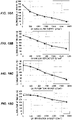
- FIGS. 18A, 18B, 18C and 18D are graphs showing the relationship between an irradiation energy (intensity (W/cm 2 ) x irradiation time (seconds)) of UV-C light and the degree of elongation at break for the samples D1, D3, D4, and D7, respectively.
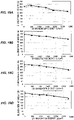
- FIGS. 19A, 19B, 19C, and 19D are graphs showing the relationship between an irradiation energy of UV-C light and the degree of elongation at break for the samples D8, D9, D10, and D11, respectively. Table 6 below shows the numerical values of the plotting points in FIGS.
- the elongation at break of the samples D7 to D11 of the elongation at break of the samples D1, D3, D4 and D7 to D11 is 250% or more, even when the elongation at break of the samples D7 to D11 is 1404 J/cm 2 , and it is confirmed that the samples D7 to D11 have high resistance to UV-C light from the viewpoint of the elongation at break.
- the elongation at break of the samples D7 to D11 of the elongation at break of the samples D1, D3, D4 and D7 to D11 is 200% or more, even when the elongation at break of the samples D7 to D11 is 1872 J/cm 2 , and it is confirmed that the samples D7 to D11 have high resistance to UV-C light from the viewpoint of the elongation at break.
- the elongation at break of the samples D7 to D11 of the elongation at break of the samples D1, D3, D4 and D7 to D11 is 150% or more, even when the elongation at break of the samples D7 to D11 is 2808 J/cm 2 , and it is confirmed that the samples D7 to D11 have high resistance to UV-C light from the viewpoint of the elongation at break.
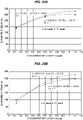
- FIGS. 18A to 18D , 19A to 19D and Table 6 It is found from the results shown in FIGS. 18A to 18D , 19A to 19D and Table 6 that it is effective to increase the amount of TiO 2 fine particles in the first layer 10 in order to increase the elongation at break of the laminate structure 1. Also, as shown in FIGS. 20A and 20B , the relationship between Ti concentration (content of TiO 2 fine particles) in the first layer 10 and the elongation at break (result of D3, D7, D10, D4, D8, and D11) is plotted, and polynomial approximations were performed.
- FIG. 20A shows the result after exposure to UV-C light at 1404 J/cm 2 .
- FIG. 20B shows the result after exposure to UV-C light at 2808 J/cm 2 .
- the Ti concentration in the first layer 10 should be 0.4 mass% or more to ensure that the elongation at break is at least 250% even after being exposed to UV-C light of 1404 J/cm 2 . In addition, it is found that the Ti concentration in the first layer 10 should be 0.35 mass% or more to ensure that the elongation at break is at least 150% even after being exposed to UV-C light of 2808 J/cm 2 .
- sample C11 including a TiO 2 fine particles 113 at a concentration of 1.9 mass% in the second layer 11 as the coating film 24 and a sample including TiO 2 fine particles 113 at a concentration of 4.4 mass% in the second layer 11 (sample C12) which was prepared similarly to the sample C11.
- sample preparation and testing for the wipe test were carried out in the same way as Japanese Patent No. 6723489 .
- Preparation of samples for measuring the static friction coefficient before and after the wipe test and measurement were performed using the same method as for Japanese Patent No. 6723489 .
- the ambient temperature was 25 +/- 3°C
- the ambient humidity was 50 +/- 10%
- the pressure was atmospheric pressure at the wiping test site and the static friction coefficient measurement site.
- Table 7 shows the values of the static friction coefficients of the coating film 24 of the measured samples C11, C12. Table 7 Before the wipe test After the wipe test The difference before and after the test (Absolute value) C11 0.167 0.188 0.019 C12 0.122 0.169 0.047
- FIGS. 21A and 21B show 1000X images of the surface before the wipe test of the samples C11 and C12, respectively.
- FIGS. 22A and 22B show the surface observations after the wipe test of the samples C11 and C12, respectively.
- Spherical particles and white powder particles around the spherical particle observed in the observation images in FIGS. 21A, 21B , 22A and 22B are the fine particles 112 and TiO 2 fine particles 113, respectively.
- the voids were more observed in the coating film 24 of the sample C12 than in the coating film 24 of the sample C11.
- the drop of fine particles 112 in the coating film of the sample C12 was more than that in the coating film 24 of the sample C11.
- concentration of TiO 2 fine particles 113 in the coating film 24 (second layer 11) of the sample C12 was too high.
- the presence of more TiO 2 fine particles 113 around the fine particle 112 has resulted in a smaller contact area between the base material 111 composed of the silicone rubber and the fine particle 112. This may have resulted in reduced adhesion.
- the upper limit of Ti concentration in the coating film 24 is 4.4 mass%.
- the preferred ranges of Ti concentrations of the first layer 10 including TiO 2 fine particles 102 and the second layer 11 including TiO 2 fine particle 113, described in the first embodiment with referring to FIG. 2 are derived from the results of tests in this example.
Landscapes
- Chemical & Material Sciences (AREA)
- Life Sciences & Earth Sciences (AREA)
- Health & Medical Sciences (AREA)
- Engineering & Computer Science (AREA)
- Materials Engineering (AREA)
- Organic Chemistry (AREA)
- Wood Science & Technology (AREA)
- Veterinary Medicine (AREA)
- Public Health (AREA)
- General Health & Medical Sciences (AREA)
- Animal Behavior & Ethology (AREA)
- Physics & Mathematics (AREA)
- Chemical Kinetics & Catalysis (AREA)
- Epidemiology (AREA)
- Inorganic Chemistry (AREA)
- Spectroscopy & Molecular Physics (AREA)
- Heart & Thoracic Surgery (AREA)
- Nuclear Medicine, Radiotherapy & Molecular Imaging (AREA)
- Medical Informatics (AREA)
- Molecular Biology (AREA)
- Surgery (AREA)
- Biophysics (AREA)
- Biomedical Technology (AREA)
- Radiology & Medical Imaging (AREA)
- Pathology (AREA)
- Computer Networks & Wireless Communication (AREA)
- Mechanical Engineering (AREA)
- Medicinal Chemistry (AREA)
- Polymers & Plastics (AREA)
- Composite Materials (AREA)
- Laminated Bodies (AREA)
- Investigating, Analyzing Materials By Fluorescence Or Luminescence (AREA)
- Insulated Conductors (AREA)
Priority Applications (2)
| Application Number | Priority Date | Filing Date | Title |
|---|---|---|---|
| EP23155000.5A EP4212328B1 (fr) | 2021-02-09 | 2022-02-08 | Structure stratifiée, câble et tube |
| EP25171206.3A EP4585418A3 (fr) | 2021-02-09 | 2022-02-08 | Structure stratifiée, câble et tube |
Applications Claiming Priority (2)
| Application Number | Priority Date | Filing Date | Title |
|---|---|---|---|
| JP2021019099A JP7567533B2 (ja) | 2021-02-09 | 2021-02-09 | 積層構造体、ケーブル及びチューブ |
| JP2021098350A JP7635645B2 (ja) | 2021-06-11 | 2021-06-11 | 積層構造体、ケーブル及びチューブ |
Related Child Applications (2)
| Application Number | Title | Priority Date | Filing Date |
|---|---|---|---|
| EP25171206.3A Division EP4585418A3 (fr) | 2021-02-09 | 2022-02-08 | Structure stratifiée, câble et tube |
| EP23155000.5A Division EP4212328B1 (fr) | 2021-02-09 | 2022-02-08 | Structure stratifiée, câble et tube |
Publications (1)
| Publication Number | Publication Date |
|---|---|
| EP4039459A1 true EP4039459A1 (fr) | 2022-08-10 |
Family
ID=80595146
Family Applications (3)
| Application Number | Title | Priority Date | Filing Date |
|---|---|---|---|
| EP23155000.5A Active EP4212328B1 (fr) | 2021-02-09 | 2022-02-08 | Structure stratifiée, câble et tube |
| EP25171206.3A Pending EP4585418A3 (fr) | 2021-02-09 | 2022-02-08 | Structure stratifiée, câble et tube |
| EP22155577.4A Pending EP4039459A1 (fr) | 2021-02-09 | 2022-02-08 | Structure stratifiée, câble et tube |
Family Applications Before (2)
| Application Number | Title | Priority Date | Filing Date |
|---|---|---|---|
| EP23155000.5A Active EP4212328B1 (fr) | 2021-02-09 | 2022-02-08 | Structure stratifiée, câble et tube |
| EP25171206.3A Pending EP4585418A3 (fr) | 2021-02-09 | 2022-02-08 | Structure stratifiée, câble et tube |
Country Status (4)
| Country | Link |
|---|---|
| US (2) | US12073964B2 (fr) |
| EP (3) | EP4212328B1 (fr) |
| KR (1) | KR102802797B1 (fr) |
| CN (1) | CN114940772A (fr) |
Citations (5)
| Publication number | Priority date | Publication date | Assignee | Title |
|---|---|---|---|---|
| JPH0423489B2 (fr) | 1981-10-25 | 1992-04-22 | Rohm Kk | |
| US5346760A (en) * | 1990-10-31 | 1994-09-13 | Total Ruffinage Distribution S.A. | Composite material based on rubbers of the silicone type and of the ethylene-propylene copolymer or terpolymer type |
| JP2013225405A (ja) * | 2012-04-20 | 2013-10-31 | Auto Network Gijutsu Kenkyusho:Kk | 絶縁電線 |
| JP2018073830A (ja) * | 2016-10-27 | 2018-05-10 | 日星電気株式会社 | 絶縁電線 |
| CN109762338A (zh) * | 2019-01-14 | 2019-05-17 | 国网西藏电力有限公司 | 添加纳米颗粒的耐紫外辐射复合绝缘子材料及制备方法 |
Family Cites Families (27)
| Publication number | Priority date | Publication date | Assignee | Title |
|---|---|---|---|---|
| US3862082A (en) * | 1973-10-31 | 1975-01-21 | Toshiba Silicone Kabushiki Kai | Flame retardant silicone rubber compositions |
| US4061503A (en) * | 1976-09-29 | 1977-12-06 | Union Carbide Corporation | Silane treatment of titanium dioxide pigment |
| DE3831479A1 (de) * | 1988-09-16 | 1990-03-29 | Wacker Chemie Gmbh | Zum beschichten der oberflaeche von elektrischen hochspannungsisolatoren geeignete massen |
| JP2670855B2 (ja) * | 1989-06-26 | 1997-10-29 | 日本合成ゴム株式会社 | シリコーン複合ゴム組成物およびその用途 |
| JPH0767784B2 (ja) * | 1990-10-11 | 1995-07-26 | 信越化学工業株式会社 | シリコーンゴム積層体及びその製造方法 |
| JP3299669B2 (ja) * | 1996-01-16 | 2002-07-08 | 信越化学工業株式会社 | 白色系の難燃性シリコーンゴム組成物 |
| FR2757869B1 (fr) * | 1996-12-31 | 1999-05-21 | Rhodia Chimie Sa | Utilisation de melanges a base de pt et de composes de metaux de transition autres que le pt pour ameliorer les proprietes de resistance a l'arc des elastomeres silicones |
| JP2000267488A (ja) * | 1999-01-11 | 2000-09-29 | Canon Inc | ロール部材およびそれを用いた定着装置 |
| FR2833937B1 (fr) * | 2001-12-26 | 2004-11-12 | Rhodia Chimie Sa | Silices a faible reprise en eau |
| US8697205B2 (en) * | 2005-05-17 | 2014-04-15 | St. Jude Medical Ab | Elastomeric tube and method of making same |
| FR2899905B1 (fr) * | 2006-04-12 | 2008-07-18 | Rhodia Recherches & Tech | Compositions polyorganosiloxanes vulcanisables a chaud utilisables notamment pour la fabrication de fils ou cables electriques |
| US20070254000A1 (en) * | 2006-04-28 | 2007-11-01 | Xiaoping Guo | Biocompatible self-lubricating polymer compositions and their use in medical and surgical devices |
| ES2414629T3 (es) * | 2008-09-29 | 2013-07-22 | E. I. Du Pont De Nemours And Company | Productos basados en polímeros que presentan una reflectancia solar mejorada y protección UV |
| GB2477932A (en) * | 2010-02-17 | 2011-08-24 | Tioxide Europe Ltd | Layered coloured reflector containing particles with rutile crystal habit and specified size |
| JP6157118B2 (ja) * | 2010-03-23 | 2017-07-05 | 株式会社朝日ラバー | 可撓性反射基材、その製造方法及びその反射基材に用いる原材料組成物 |
| JP6699119B2 (ja) * | 2015-01-22 | 2020-05-27 | 株式会社リコー | 素子及び発電装置 |
| US9665049B2 (en) * | 2015-02-26 | 2017-05-30 | Canon Kabushiki Kaisha | Member for electrophotography, method for manufacturing member for electrophotography, and image-forming apparatus |
| US20170011820A1 (en) * | 2015-07-10 | 2017-01-12 | General Electric Company | Insulated windings and methods of making thereof |
| US10258765B2 (en) * | 2016-08-02 | 2019-04-16 | Hitachi Metals, Ltd. | Cable and medical hollow tube |
| US10465270B1 (en) * | 2017-01-30 | 2019-11-05 | General Cable Technologies Corporation | Cables having conductive elements formed from aluminum alloys processed with high shear deformation processes |
| KR102387358B1 (ko) * | 2018-05-17 | 2022-04-14 | 히타치 긴조쿠 가부시키가이샤 | 케이블 및 의료용 중공관 |
| WO2020022407A1 (fr) * | 2018-07-25 | 2020-01-30 | ダウ・東レ株式会社 | Composition de caoutchouc de silicone et procédé de production de stratifié de caoutchouc de silicone fluorée et caoutchouc de silicone |
| KR102229141B1 (ko) | 2019-09-13 | 2021-03-17 | 히타치 긴조쿠 가부시키가이샤 | 케이블 및 의료용 중공관 |
| JP6723489B1 (ja) | 2019-09-13 | 2020-07-15 | 日立金属株式会社 | ケーブルおよび医療用中空管 |
| US11779193B2 (en) | 2019-09-13 | 2023-10-10 | Proterial, Ltd. | Molded article and hollow tube |
| US11069460B1 (en) * | 2020-08-11 | 2021-07-20 | Prysmian S.P.A. | Fire resistant cable with dual insulation layer arrangement |
| US11987024B2 (en) * | 2020-09-25 | 2024-05-21 | Carefusion 303, Inc. | Multilayer tubing having intermediate layer with additives |
-
2022
- 2022-02-07 US US17/666,190 patent/US12073964B2/en active Active
- 2022-02-08 EP EP23155000.5A patent/EP4212328B1/fr active Active
- 2022-02-08 EP EP25171206.3A patent/EP4585418A3/fr active Pending
- 2022-02-08 EP EP22155577.4A patent/EP4039459A1/fr active Pending
- 2022-02-08 KR KR1020220016204A patent/KR102802797B1/ko active Active
- 2022-02-08 CN CN202210133630.0A patent/CN114940772A/zh active Pending
-
2024
- 2024-04-25 US US18/646,595 patent/US20240296971A1/en active Pending
Patent Citations (5)
| Publication number | Priority date | Publication date | Assignee | Title |
|---|---|---|---|---|
| JPH0423489B2 (fr) | 1981-10-25 | 1992-04-22 | Rohm Kk | |
| US5346760A (en) * | 1990-10-31 | 1994-09-13 | Total Ruffinage Distribution S.A. | Composite material based on rubbers of the silicone type and of the ethylene-propylene copolymer or terpolymer type |
| JP2013225405A (ja) * | 2012-04-20 | 2013-10-31 | Auto Network Gijutsu Kenkyusho:Kk | 絶縁電線 |
| JP2018073830A (ja) * | 2016-10-27 | 2018-05-10 | 日星電気株式会社 | 絶縁電線 |
| CN109762338A (zh) * | 2019-01-14 | 2019-05-17 | 国网西藏电力有限公司 | 添加纳米颗粒的耐紫外辐射复合绝缘子材料及制备方法 |
Also Published As
| Publication number | Publication date |
|---|---|
| EP4585418A3 (fr) | 2025-10-15 |
| US20240296971A1 (en) | 2024-09-05 |
| EP4212328A1 (fr) | 2023-07-19 |
| EP4585418A2 (fr) | 2025-07-16 |
| US20220254543A1 (en) | 2022-08-11 |
| KR20220115523A (ko) | 2022-08-17 |
| EP4212328B1 (fr) | 2025-06-25 |
| US12073964B2 (en) | 2024-08-27 |
| KR102802797B1 (ko) | 2025-05-02 |
| CN114940772A (zh) | 2022-08-26 |
Similar Documents
| Publication | Publication Date | Title |
|---|---|---|
| JP7094427B2 (ja) | ケーブル、医療用中空管、成形体及び中空管 | |
| JP7848906B2 (ja) | 積層構造体、ケーブル、チューブ及び積層構造体の製造方法 | |
| JP6723489B1 (ja) | ケーブルおよび医療用中空管 | |
| CN110504065B (zh) | 电缆和医疗用中空管 | |
| EP4039459A1 (fr) | Structure stratifiée, câble et tube | |
| CN114334246A (zh) | 电缆和医疗用中空管 | |
| Ahmad et al. | AC performance of HTV-SR and its hybrids loaded with nano-/micro-silica/ATH fillers | |
| US11401439B2 (en) | Molded article and hollow tube | |
| US20230077911A1 (en) | Resin composition quality controlling method, cable and tube quality controlling method, determination device, inspection system, cable, and tube | |
| JP7816450B2 (ja) | 積層構造体の製造方法、ケーブルの製造方法及びチューブの製造方法 | |
| JP7321111B2 (ja) | ケーブルおよび医療用中空管 | |
| US20240110077A1 (en) | Resin composition, laminate structure, cable, tube, and method for manufacturing resin composition | |
| JP7459695B2 (ja) | シリコーンゴムの品質管理方法、ケーブル又はチューブの品質管理方法、並びに積層構造体の製造方法 | |
| CN121825403A (zh) | 有机硅涂膜、层叠结构体及层叠结构体的制造方法 |
Legal Events
| Date | Code | Title | Description |
|---|---|---|---|
| PUAI | Public reference made under article 153(3) epc to a published international application that has entered the european phase |
Free format text: ORIGINAL CODE: 0009012 |
|
| STAA | Information on the status of an ep patent application or granted ep patent |
Free format text: STATUS: THE APPLICATION HAS BEEN PUBLISHED |
|
| AK | Designated contracting states |
Kind code of ref document: A1 Designated state(s): AL AT BE BG CH CY CZ DE DK EE ES FI FR GB GR HR HU IE IS IT LI LT LU LV MC MK MT NL NO PL PT RO RS SE SI SK SM TR |
|
| STAA | Information on the status of an ep patent application or granted ep patent |
Free format text: STATUS: REQUEST FOR EXAMINATION WAS MADE |
|
| 17P | Request for examination filed |
Effective date: 20230210 |
|
| RBV | Designated contracting states (corrected) |
Designated state(s): AL AT BE BG CH CY CZ DE DK EE ES FI FR GB GR HR HU IE IS IT LI LT LU LV MC MK MT NL NO PL PT RO RS SE SI SK SM TR |
|
| RAP3 | Party data changed (applicant data changed or rights of an application transferred) |
Owner name: PROTERIAL, LTD. |
|
| STAA | Information on the status of an ep patent application or granted ep patent |
Free format text: STATUS: EXAMINATION IS IN PROGRESS |
|
| 17Q | First examination report despatched |
Effective date: 20251218 |