EP4039523B1 - Elektromobilitätssystem für ein fahrzeug - Google Patents
Elektromobilitätssystem für ein fahrzeug Download PDFInfo
- Publication number
- EP4039523B1 EP4039523B1 EP21155124.7A EP21155124A EP4039523B1 EP 4039523 B1 EP4039523 B1 EP 4039523B1 EP 21155124 A EP21155124 A EP 21155124A EP 4039523 B1 EP4039523 B1 EP 4039523B1
- Authority
- EP
- European Patent Office
- Prior art keywords
- battery pack
- sub
- pack arrangement
- electromobility
- converter
- Prior art date
- Legal status (The legal status is an assumption and is not a legal conclusion. Google has not performed a legal analysis and makes no representation as to the accuracy of the status listed.)
- Active
Links
Images

Classifications
-
- B—PERFORMING OPERATIONS; TRANSPORTING
- B60—VEHICLES IN GENERAL
- B60L—PROPULSION OF ELECTRICALLY-PROPELLED VEHICLES; SUPPLYING ELECTRIC POWER FOR AUXILIARY EQUIPMENT OF ELECTRICALLY-PROPELLED VEHICLES; ELECTRODYNAMIC BRAKE SYSTEMS FOR VEHICLES IN GENERAL; MAGNETIC SUSPENSION OR LEVITATION FOR VEHICLES; MONITORING OPERATING VARIABLES OF ELECTRICALLY-PROPELLED VEHICLES; ELECTRIC SAFETY DEVICES FOR ELECTRICALLY-PROPELLED VEHICLES
- B60L1/00—Supplying electric power to auxiliary equipment of vehicles
- B60L1/003—Supplying electric power to auxiliary equipment of vehicles to auxiliary motors, e.g. for pumps, compressors
-
- B—PERFORMING OPERATIONS; TRANSPORTING
- B60—VEHICLES IN GENERAL
- B60K—ARRANGEMENT OR MOUNTING OF PROPULSION UNITS OR OF TRANSMISSIONS IN VEHICLES; ARRANGEMENT OR MOUNTING OF PLURAL DIVERSE PRIME-MOVERS IN VEHICLES; AUXILIARY DRIVES FOR VEHICLES; INSTRUMENTATION OR DASHBOARDS FOR VEHICLES; ARRANGEMENTS IN CONNECTION WITH COOLING, AIR INTAKE, GAS EXHAUST OR FUEL SUPPLY OF PROPULSION UNITS IN VEHICLES
- B60K1/00—Arrangement or mounting of electrical propulsion units
-
- B—PERFORMING OPERATIONS; TRANSPORTING
- B60—VEHICLES IN GENERAL
- B60K—ARRANGEMENT OR MOUNTING OF PROPULSION UNITS OR OF TRANSMISSIONS IN VEHICLES; ARRANGEMENT OR MOUNTING OF PLURAL DIVERSE PRIME-MOVERS IN VEHICLES; AUXILIARY DRIVES FOR VEHICLES; INSTRUMENTATION OR DASHBOARDS FOR VEHICLES; ARRANGEMENTS IN CONNECTION WITH COOLING, AIR INTAKE, GAS EXHAUST OR FUEL SUPPLY OF PROPULSION UNITS IN VEHICLES
- B60K1/00—Arrangement or mounting of electrical propulsion units
- B60K1/04—Arrangement or mounting of electrical propulsion units of the electric storage means for propulsion
-
- B—PERFORMING OPERATIONS; TRANSPORTING
- B60—VEHICLES IN GENERAL
- B60L—PROPULSION OF ELECTRICALLY-PROPELLED VEHICLES; SUPPLYING ELECTRIC POWER FOR AUXILIARY EQUIPMENT OF ELECTRICALLY-PROPELLED VEHICLES; ELECTRODYNAMIC BRAKE SYSTEMS FOR VEHICLES IN GENERAL; MAGNETIC SUSPENSION OR LEVITATION FOR VEHICLES; MONITORING OPERATING VARIABLES OF ELECTRICALLY-PROPELLED VEHICLES; ELECTRIC SAFETY DEVICES FOR ELECTRICALLY-PROPELLED VEHICLES
- B60L1/00—Supplying electric power to auxiliary equipment of vehicles
-
- B—PERFORMING OPERATIONS; TRANSPORTING
- B60—VEHICLES IN GENERAL
- B60L—PROPULSION OF ELECTRICALLY-PROPELLED VEHICLES; SUPPLYING ELECTRIC POWER FOR AUXILIARY EQUIPMENT OF ELECTRICALLY-PROPELLED VEHICLES; ELECTRODYNAMIC BRAKE SYSTEMS FOR VEHICLES IN GENERAL; MAGNETIC SUSPENSION OR LEVITATION FOR VEHICLES; MONITORING OPERATING VARIABLES OF ELECTRICALLY-PROPELLED VEHICLES; ELECTRIC SAFETY DEVICES FOR ELECTRICALLY-PROPELLED VEHICLES
- B60L50/00—Electric propulsion with power supplied within the vehicle
- B60L50/50—Electric propulsion with power supplied within the vehicle using propulsion power supplied by batteries or fuel cells
- B60L50/60—Electric propulsion with power supplied within the vehicle using propulsion power supplied by batteries or fuel cells using power supplied by batteries
-
- B—PERFORMING OPERATIONS; TRANSPORTING
- B60—VEHICLES IN GENERAL
- B60L—PROPULSION OF ELECTRICALLY-PROPELLED VEHICLES; SUPPLYING ELECTRIC POWER FOR AUXILIARY EQUIPMENT OF ELECTRICALLY-PROPELLED VEHICLES; ELECTRODYNAMIC BRAKE SYSTEMS FOR VEHICLES IN GENERAL; MAGNETIC SUSPENSION OR LEVITATION FOR VEHICLES; MONITORING OPERATING VARIABLES OF ELECTRICALLY-PROPELLED VEHICLES; ELECTRIC SAFETY DEVICES FOR ELECTRICALLY-PROPELLED VEHICLES
- B60L58/00—Methods or circuit arrangements for monitoring or controlling batteries or fuel cells, specially adapted for electric vehicles
- B60L58/10—Methods or circuit arrangements for monitoring or controlling batteries or fuel cells, specially adapted for electric vehicles for monitoring or controlling batteries
- B60L58/18—Methods or circuit arrangements for monitoring or controlling batteries or fuel cells, specially adapted for electric vehicles for monitoring or controlling batteries of two or more battery modules
- B60L58/20—Methods or circuit arrangements for monitoring or controlling batteries or fuel cells, specially adapted for electric vehicles for monitoring or controlling batteries of two or more battery modules having different nominal voltages
-
- H—ELECTRICITY
- H02—GENERATION; CONVERSION OR DISTRIBUTION OF ELECTRIC POWER
- H02J—ELECTRIC POWER NETWORKS; CIRCUIT ARRANGEMENTS OR SYSTEMS FOR SUPPLYING OR DISTRIBUTING ELECTRIC POWER; SYSTEMS FOR STORING ELECTRIC ENERGY
- H02J1/00—Circuit arrangements for DC mains or DC distribution networks
- H02J1/10—Parallel operation of DC sources
-
- H—ELECTRICITY
- H02—GENERATION; CONVERSION OR DISTRIBUTION OF ELECTRIC POWER
- H02J—ELECTRIC POWER NETWORKS; CIRCUIT ARRANGEMENTS OR SYSTEMS FOR SUPPLYING OR DISTRIBUTING ELECTRIC POWER; SYSTEMS FOR STORING ELECTRIC ENERGY
- H02J7/00—Circuit arrangements for charging or discharging batteries or for supplying loads from batteries
- H02J7/34—Parallel operation in networks using both storage and other DC sources, e.g. providing buffering
- H02J7/342—The other DC source being a battery actively interacting with the first one, i.e. battery to battery charging
-
- B—PERFORMING OPERATIONS; TRANSPORTING
- B60—VEHICLES IN GENERAL
- B60L—PROPULSION OF ELECTRICALLY-PROPELLED VEHICLES; SUPPLYING ELECTRIC POWER FOR AUXILIARY EQUIPMENT OF ELECTRICALLY-PROPELLED VEHICLES; ELECTRODYNAMIC BRAKE SYSTEMS FOR VEHICLES IN GENERAL; MAGNETIC SUSPENSION OR LEVITATION FOR VEHICLES; MONITORING OPERATING VARIABLES OF ELECTRICALLY-PROPELLED VEHICLES; ELECTRIC SAFETY DEVICES FOR ELECTRICALLY-PROPELLED VEHICLES
- B60L2200/00—Type of vehicles
- B60L2200/36—Vehicles designed to transport cargo, e.g. trucks
-
- B—PERFORMING OPERATIONS; TRANSPORTING
- B60—VEHICLES IN GENERAL
- B60L—PROPULSION OF ELECTRICALLY-PROPELLED VEHICLES; SUPPLYING ELECTRIC POWER FOR AUXILIARY EQUIPMENT OF ELECTRICALLY-PROPELLED VEHICLES; ELECTRODYNAMIC BRAKE SYSTEMS FOR VEHICLES IN GENERAL; MAGNETIC SUSPENSION OR LEVITATION FOR VEHICLES; MONITORING OPERATING VARIABLES OF ELECTRICALLY-PROPELLED VEHICLES; ELECTRIC SAFETY DEVICES FOR ELECTRICALLY-PROPELLED VEHICLES
- B60L2200/00—Type of vehicles
- B60L2200/40—Working vehicles
-
- B—PERFORMING OPERATIONS; TRANSPORTING
- B60—VEHICLES IN GENERAL
- B60L—PROPULSION OF ELECTRICALLY-PROPELLED VEHICLES; SUPPLYING ELECTRIC POWER FOR AUXILIARY EQUIPMENT OF ELECTRICALLY-PROPELLED VEHICLES; ELECTRODYNAMIC BRAKE SYSTEMS FOR VEHICLES IN GENERAL; MAGNETIC SUSPENSION OR LEVITATION FOR VEHICLES; MONITORING OPERATING VARIABLES OF ELECTRICALLY-PROPELLED VEHICLES; ELECTRIC SAFETY DEVICES FOR ELECTRICALLY-PROPELLED VEHICLES
- B60L2210/00—Converter types
- B60L2210/10—DC to DC converters
-
- B—PERFORMING OPERATIONS; TRANSPORTING
- B60—VEHICLES IN GENERAL
- B60Y—INDEXING SCHEME RELATING TO ASPECTS CROSS-CUTTING VEHICLE TECHNOLOGY
- B60Y2200/00—Type of vehicle
- B60Y2200/10—Road Vehicles
- B60Y2200/14—Trucks; Load vehicles, Busses
- B60Y2200/142—Heavy duty trucks
- B60Y2200/1422—Multi-axle trucks
-
- H—ELECTRICITY
- H02—GENERATION; CONVERSION OR DISTRIBUTION OF ELECTRIC POWER
- H02J—ELECTRIC POWER NETWORKS; CIRCUIT ARRANGEMENTS OR SYSTEMS FOR SUPPLYING OR DISTRIBUTING ELECTRIC POWER; SYSTEMS FOR STORING ELECTRIC ENERGY
- H02J2105/00—Networks for supplying or distributing electric power characterised by their spatial reach or by the load
- H02J2105/30—Networks for supplying or distributing electric power characterised by their spatial reach or by the load the load networks being external to vehicles, i.e. exchanging power with vehicles
- H02J2105/33—Networks for supplying or distributing electric power characterised by their spatial reach or by the load the load networks being external to vehicles, i.e. exchanging power with vehicles exchanging power with road vehicles
- H02J2105/37—Networks for supplying or distributing electric power characterised by their spatial reach or by the load the load networks being external to vehicles, i.e. exchanging power with vehicles exchanging power with road vehicles exchanging power with electric vehicles [EV] or with hybrid electric vehicles [HEV]
-
- H—ELECTRICITY
- H02—GENERATION; CONVERSION OR DISTRIBUTION OF ELECTRIC POWER
- H02M—APPARATUS FOR CONVERSION BETWEEN AC AND AC, BETWEEN AC AND DC, OR BETWEEN DC AND DC, AND FOR USE WITH MAINS OR SIMILAR POWER SUPPLY SYSTEMS; CONVERSION OF DC OR AC INPUT POWER INTO SURGE OUTPUT POWER; CONTROL OR REGULATION THEREOF
- H02M3/00—Conversion of DC power input into DC power output
- H02M3/22—Conversion of DC power input into DC power output with intermediate conversion into AC
- H02M3/24—Conversion of DC power input into DC power output with intermediate conversion into AC by static converters
- H02M3/28—Conversion of DC power input into DC power output with intermediate conversion into AC by static converters using discharge tubes with control electrode or semiconductor devices with control electrode to produce the intermediate AC
- H02M3/325—Conversion of DC power input into DC power output with intermediate conversion into AC by static converters using discharge tubes with control electrode or semiconductor devices with control electrode to produce the intermediate AC using devices of a triode or a transistor type requiring continuous application of a control signal
- H02M3/335—Conversion of DC power input into DC power output with intermediate conversion into AC by static converters using discharge tubes with control electrode or semiconductor devices with control electrode to produce the intermediate AC using devices of a triode or a transistor type requiring continuous application of a control signal using semiconductor devices only
- H02M3/33507—Conversion of DC power input into DC power output with intermediate conversion into AC by static converters using discharge tubes with control electrode or semiconductor devices with control electrode to produce the intermediate AC using devices of a triode or a transistor type requiring continuous application of a control signal using semiconductor devices only with automatic control of the output voltage or current, e.g. flyback converters
- H02M3/33523—Conversion of DC power input into DC power output with intermediate conversion into AC by static converters using discharge tubes with control electrode or semiconductor devices with control electrode to produce the intermediate AC using devices of a triode or a transistor type requiring continuous application of a control signal using semiconductor devices only with automatic control of the output voltage or current, e.g. flyback converters with galvanic isolation between input and output of both the power stage and the feedback loop
-
- H—ELECTRICITY
- H02—GENERATION; CONVERSION OR DISTRIBUTION OF ELECTRIC POWER
- H02M—APPARATUS FOR CONVERSION BETWEEN AC AND AC, BETWEEN AC AND DC, OR BETWEEN DC AND DC, AND FOR USE WITH MAINS OR SIMILAR POWER SUPPLY SYSTEMS; CONVERSION OF DC OR AC INPUT POWER INTO SURGE OUTPUT POWER; CONTROL OR REGULATION THEREOF
- H02M3/00—Conversion of DC power input into DC power output
- H02M3/22—Conversion of DC power input into DC power output with intermediate conversion into AC
- H02M3/24—Conversion of DC power input into DC power output with intermediate conversion into AC by static converters
- H02M3/28—Conversion of DC power input into DC power output with intermediate conversion into AC by static converters using discharge tubes with control electrode or semiconductor devices with control electrode to produce the intermediate AC
- H02M3/325—Conversion of DC power input into DC power output with intermediate conversion into AC by static converters using discharge tubes with control electrode or semiconductor devices with control electrode to produce the intermediate AC using devices of a triode or a transistor type requiring continuous application of a control signal
- H02M3/335—Conversion of DC power input into DC power output with intermediate conversion into AC by static converters using discharge tubes with control electrode or semiconductor devices with control electrode to produce the intermediate AC using devices of a triode or a transistor type requiring continuous application of a control signal using semiconductor devices only
- H02M3/33569—Conversion of DC power input into DC power output with intermediate conversion into AC by static converters using discharge tubes with control electrode or semiconductor devices with control electrode to produce the intermediate AC using devices of a triode or a transistor type requiring continuous application of a control signal using semiconductor devices only having several active switching elements
- H02M3/33576—Conversion of DC power input into DC power output with intermediate conversion into AC by static converters using discharge tubes with control electrode or semiconductor devices with control electrode to produce the intermediate AC using devices of a triode or a transistor type requiring continuous application of a control signal using semiconductor devices only having several active switching elements having at least one active switching element at the secondary side of an isolation transformer
- H02M3/33584—Bidirectional converters
-
- Y—GENERAL TAGGING OF NEW TECHNOLOGICAL DEVELOPMENTS; GENERAL TAGGING OF CROSS-SECTIONAL TECHNOLOGIES SPANNING OVER SEVERAL SECTIONS OF THE IPC; TECHNICAL SUBJECTS COVERED BY FORMER USPC CROSS-REFERENCE ART COLLECTIONS [XRACs] AND DIGESTS
- Y02—TECHNOLOGIES OR APPLICATIONS FOR MITIGATION OR ADAPTATION AGAINST CLIMATE CHANGE
- Y02T—CLIMATE CHANGE MITIGATION TECHNOLOGIES RELATED TO TRANSPORTATION
- Y02T10/00—Road transport of goods or passengers
- Y02T10/60—Other road transportation technologies with climate change mitigation effect
- Y02T10/70—Energy storage systems for electromobility, e.g. batteries
Definitions
- the present invention relates to an electromobility system for a vehicle.
- the invention further relates to a method for operating an electromobility system in a vehicle, a computer program, a computer readable medium and to a vehicle.
- a vehicle typically comprises an engine or machine for propelling the vehicle.
- the engine may be powered by various means, such as e.g. by a liquid or gaseous fuel in an internal combustion engine, or by electric power to an electric machine.
- hybrid solutions exist in which e.g. the vehicle is propelled both by an internal combustion engine and an electric machine. In either way, an energy storage device is used to store the energy needed in order to propel the vehicle. Energy storage devices may further be used to power auxiliary loads and auxiliary equipment in the vehicle.
- the energy storage devices are comprised in an energy storage system, wherein the energy storage system is configured to power an engine or machine for propelling the vehicle, and any auxiliary loads via an electromobility system.
- an auxiliary equipment typically being a bodybuilder application such as e.g. a lifting arrangement or cement mixer, is in need of electrical powering.
- the electromobility system of the vehicle may be configured to operate the electric machine as well as any electrically driven auxiliary equipment or bodybuilder application.
- WO2017/173420 and US2020/001720 disclose electromobility systems comprising a first and second battery systems in which the two battery systems may be operated independently of each other to power high voltage loads and low voltage loads.
- US 2010/133900 A1 discloses an electromobility system for a vehicle comprising a primary sub-system including at least a first battery pack arrangement configured to power an electric machine for propelling the vehicle, a secondary sub-system including at least a second battery pack arrangement configured to power an auxiliary equipment, and a DC/DC-converter arranged and configured to galvanically separate the first sub-system from the second sub-system.
- the auxiliary equipment or bodybuilder application may be an add-on to the vehicle, and thus be installed subsequently to designing and manufacturing the vehicle itself.
- the current electromobility system of the vehicle is often used also to power the added auxiliary equipment or bodybuilder application.
- the electrical properties, and power requirements typically vary depending on the nature of the add-on, and as the current electromobility system of the vehicle has certain limitations, the auxiliary equipment or bodybuilder application added to vehicle must be carefully chosen and/or requires cumbersome retrofitting of the vehicle's electromobility system. There is thus a need in the industry for an improved electromobility system of the vehicle.
- an electromobility system for a vehicle is provided as defined in claim 1.
- the primary sub-system may be operated autonomously of the secondary sub-system.
- different secondary sub-systems may be connected via the DC/DC-converter to the primary sub-system, without changing the configuration, design or operational power of the primary sub-system.
- the secondary sub-system may change without changing the configuration, design or operational power of the primary sub-system.
- the primary sub-system may be designed and manufactured together with the vehicle without any adaptions being made for any later connected secondary sub-system or the secondary battery pack arrangement, potentially except for the DC/DC-converter.
- the secondary sub-system may be designed and adapted to the auxiliary equipment without any adaptions being made for the primary sub-system and the functionality of powering the electric machine for propelling the vehicle.
- the auxiliary equipment being for example a bodybuilder application, may be varied without concerns of the primary sub-system and the functionality of powering the electric machine for propelling the vehicle, as the adaption in relation to the various auxiliary equipment is made by the secondary sub-system.
- isolation, inductance and capacitance are split in two sub-systems (primary and secondary) with their respective sub-system properties.
- the properties of the primary sub-system are not impacted by the auxiliary equipment, and the properties of the primary sub-system may thus be better tuned to be compatible with e.g. the capacitance restrictions imposed from connection to the charging infrastructure.
- the properties of secondary sub-system allow for larger variations of contribution to such properties from the auxiliary equipment.
- the electromobility system may be simply referred to as an electrical system, or an electrical system for a vehicle.
- a particular property of the electromobility system is harmonics.
- Switching power electronic converter units create harmonics (voltage ripple), which propagate along cables in the system. Harmonics from different sources add up to complex harmonics and may lead to durability issues and/or functional breakdown.
- a DC/DC-converter arranged and configured to galvanically separate the primary sub-system from the secondary sub-system, the insensitivity to harmonic disturbances between the auxiliary equipment and components of the primary sub-system is improved.
- a further advantage of galvanically separating the primary sub-system from the secondary sub-system is that the risk of unwanted interference by the auxiliary equipment is reduced. For example, containment of a fault in the auxiliary equipment and/or the secondary sub-system is improved resulting in a reduced the risk of jeopardizing the functionality of the primary sub-system.
- the vehicle's electromobility system typically comprises a protective system to avoid electric shock or arcing events causing disturbances or even interruption of the propulsion of the vehicle
- conventional addition of unknown auxiliary equipment to the system requires that the added auxiliary equipment is fully compliant with the existing protective systems, which is quite constraining to the added auxiliary equipment.
- the electric machine in the primary sub-system and the auxiliary equipment in the secondary sub-system may be operated independently in the first state.
- the auxiliary equipment may be operated in accordance with a base load.
- more power than what is provided by the secondary sub-system may be used to power the auxiliary equipment, for example during a high or maximum load of the auxiliary equipment.
- the capacity of DC/DC-converter can be more freely chosen, with maintained functionality of the system.
- the DC/DC-converter can be reduced in size and capacity compared to a system in which the auxiliary equipment is not powered by a battery pack arrangement configured to power the auxiliary equipment independently of the primary sub-system.
- At least one battery pack in the second battery pack arrangement powers the auxiliary equipment
- at least one battery pack in the second battery pack arrangement powers the auxiliary equipment together with at least one battery pack of the first battery pack arrangement.
- the battery pack(s) of the second battery pack arrangement may be referred to as second battery pack(s) or secondary battery pack(s) and/or the second battery pack arrangement may be referred to as a secondary battery pack arrangement.
- the second battery pack arrangement is, in the electromobility system, arranged to be galvanically separated by means of the DC/DC-converter from the first battery pack arrangement, while still being operable to power the auxiliary equipment in the secondary sub-system.
- at least one battery pack of the second battery pack arrangement is, in the electromobility system, arranged to be galvanically separated by means of the DC/DC-converter from at least one battery pack of the first battery pack arrangement, while still being operable to power the auxiliary equipment in the secondary sub-system.
- all of the battery packs in the second battery pack arrangement are, in the electromobility system, galvanically separated by means of the DC/DC-converter from all of the battery packs in the first battery pack arrangement.
- the system is configured to, in the first state, power the electric machine by the first battery pack arrangement of the primary sub-system independently of the second battery pack arrangement, and power the auxiliary equipment by the second battery pack arrangement in the secondary sub-system independently of the first battery pack arrangement.
- the system in the second state, is configured to power the auxiliary equipment by the second battery pack arrangement and the first battery pack arrangement, wherein power from the first battery pack arrangement is transferred via the DC/DC-converter.
- the auxiliary equipment in the second state, is powered by the secondary sub-system and the primary sub-system.
- the DC/DC-converter in the first state, is not transferring power, and may be referred to as being in an inactive condition.
- the electric machine is powered by the first battery pack arrangement independently of the DC/DC-converter
- the auxiliary equipment is powered by the second battery pack arrangement independently of the DC/DC-converter.
- the DC/DC-converter In the second state, the DC/DC-converter is transferring power from the primary sub-system to the secondary sub-system, and may be referred to as being in an active condition.
- the system is configured to, in the second state, power the electric machine by the first battery pack arrangement of the primary sub-system in addition to transferring power to the secondary sub-system via the DC/DC-converter.
- the primary sub-system is configured to galvanically connect the first battery pack arrangement with the electric machine
- the secondary sub-system is configured to galvanically connect the second battery pack arrangement with the auxiliary equipment.
- the electromobility system may e.g. comprise a network of cables or similar that galvanically connects the electrical components as the battery packs and loads.
- the network of cables is divided into a first network of cables for connecting electrical components in the primary sub-system, and a second network of cables for connecting electrical components in the secondary sub-system.
- one or more busbars and/or one or more junction boxes may be used in the network of cables.
- a first junction box is used within the first network of cables and a second junction box is used within with the second network of cables.
- the network of cables has a daisy chain arrangement.
- the auxiliary equipment is galvanically separated from the primary sub-system. According to at least one non-claimed example, the auxiliary equipment is separated from the primary sub-system. According to at least one non-claimed example, the auxiliary equipment is not part of the primary sub-system.
- the DC/DC-converter is a galvanically separating DC/DC-converter.
- the primary sub-system and the secondary sub-system are galvanically separated by means of the galvanically separating DC/DC-converter.
- the galvanically separating DC/DC-converter may be referred to as an isolating DC/DC-converter.
- the first battery pack arrangement is galvanically connected to the electric machine and galvanically separated or isolated from the auxiliary equipment by means of the galvanically isolated DC/DC-converter
- the second battery pack arrangement is galvanically connected to the auxiliary equipment, and galvanically separated or isolated from the electric machine by means of the galvanically isolated DC/DC-converter.
- the DC/DC-converter is a unidirectional DC/DC-converter configured to transfer power from the primary sub-system to the secondary sub-system.
- the DC/DC-converter may be made less complex while still serving the purpose of transferring power from the primary sub-system to the auxiliary equipment in the second state.
- the DC/DC-converter is a bidirectional DC/DC-converter configured to transfer power from the primary sub-system to the secondary sub-system, and from the secondary sub-system to the primary sub-system.
- the system may be configured to, in a third state, supply power to the primary sub-system, e.g. powering an auxiliary load or the electric machine, from the second battery pack arrangement of the secondary sub-system via the DC/DC-converter.
- the battery pack(s) of the first battery pack arrangement may be charged by means of the secondary battery pack arrangement via the DC/DC-converter (e.g. in the third state, or in a separate alternative third state).
- the system is configured to charge the second battery pack arrangement of the secondary sub-system by the primary sub-system via the DC/DC-converter.
- Charging of the second battery pack arrangement of the secondary sub-system by the primary sub-system via the DC/DC-converter may e.g. be performed by the first battery pack arrangement or a charging interface. Such charging is typically performed in the second state, or in a separate alternative second state.
- the operating voltage of the secondary sub-system is between 60 V and 850 V.
- the secondary sub-system is configured to power corresponding electrical components or loads, such as the auxiliary equipment.
- the secondary sub-system is typically configured for direct current (DC).
- the operating voltage of the secondary sub-system is between 80 V and 850 V, or between 100 V and 850 V, or between 120 V and 850 V, or between 220 V and 850 V, or between 400 V and 850 V.
- the operating voltage of the secondary sub-system is between 80 V and 400 V, or between 80 V and 220 V, or between 80 V and 120 V, or between 80 V and 100 V.
- the secondary sub-system is a high voltage sub-system.
- the second battery pack arrangement is a high voltage battery pack arrangement of between 60 V and 850 V.
- the operating voltage of the primary sub-system is between 500 V and 1500 V.
- the operating voltage of the primary sub-system is between 550 V and 1500 V, or between 580 V and 1500 V, or between 750 V and 1500 V, or between 850 V and 1500 V, or between 1000 V and 1500 V.
- the operating voltage of the secondary sub-system is between 500 V and 850 V, such as e.g. between 580 V and 850 V or between 550 V and 750 V.
- the operating voltage of the primary sub-system is higher than then operating voltage of the secondary sub-system. According to at least one example embodiment, the operating voltage of the primary sub-system is at least twice as high as the operating voltage of the secondary sub-system.
- the auxiliary equipment is a vehicle bodybuilder application.
- the vehicle bodybuilder application is at least one of the following: cement mixer, refuse truck equipment, crane, hook lift, tipper, refrigeration (e.g. heat pump and/or fans), car transporter lifter and ramps, sewage/slurry truck pump, bulk compressor, access vehicle ladder and firetruck equipment.
- the bodybuilder application may be a truck bodybuilder application.
- the power requirement of the auxiliary equipment or vehicle bodybuilder application is at least 10 kW, or at least 20 kW.
- the auxiliary equipment is referred to as a bodybuilder equipment.
- the auxiliary equipment is a high voltage equipment or a high voltage auxiliary equipment.
- the auxiliary equipment is different to an auxiliary load of the primary sub-system.
- Such auxiliary load of the primary sub-system may be one of the following: coolant pumps, coolant fans, coolant heater, air compressor (for brakes), AC compressor (climate), heat pumps (in cooling system), defrosters, cab climate units, cab living equipment (lamp, microwave, TV, etc.).
- the electrical properties of the first battery pack arrangement is different to the electrical properties of the second battery pack arrangement.
- the electrical properties of the battery pack(s) in the first battery pack arrangement is different to the electrical properties of the battery pack(s) in the second battery pack arrangement.
- the different electrical properties may here be referring to different operating voltage, different internal resistance, different energy storage capacity, different charge/discharge power abilities, different cell chemistry and/or different electro-chemical properties.
- the electromobility system comprises a switch arranged in parallel to the DC/DC-converter and configured to galvanically connect the primary sub-system with the secondary sub-system in coupled state.
- the primary sub-system and the secondary sub-system may be galvanically connected, e.g. by providing a low-ohmic connection between the primary and the secondary sub-systems.
- the system may be configured to, in the coupled state, galvanically connect the primary sub-system with the secondary sub-system.
- a galvanically connected system of the primary and secondary sub-systems can be realised at will by applying the switch, and the advantages of a galvanically connected system assimilated.
- a galvanic separation of the primary and secondary sub-systems can be realised at will by applying the switch, and the disadvantages of having a galvanically connected system avoided.
- the switch may typically comprise a contactor, or other electrically controlled switch.
- the secondary sub-system may be changed without effecting the primary sub-system.
- the galvanically separated sub-systems provide for the possibility to change, adapt or exchange the secondary sub-system without changing the configuration, design or operational power of the primary sub-system.
- a method for operating an electromobility system in a vehicle is provided as defined in claim 10.
- the method comprises charging the second battery pack of the secondary sub-system by the primary sub-system via the DC/DC-converter.
- the charging may be performed by the first battery pack arrangement or a charging interface of the primary sub-system which is connected to the grid. Such charging may e.g. be performed in the second state.
- the DC/DC-converter may be a bidirectional DC/DC-converter configured to transfer power from the primary sub-system to the secondary sub-system, and from the secondary sub-system to the primary sub-system.
- the method may comprise, in a third state, supplying power to the primary sub-system, e.g. powering an auxiliary load or the electric machine, from the second battery pack arrangement of the secondary sub-system via the DC/DC-converter.
- the method may comprise charging the battery pack(s) of the first battery pack arrangement by means of the secondary battery pack arrangement via the DC/DC-converter (e.g. in the third state, or in a separate alternative third state).
- a computer program comprising program code means for performing the method according to the second aspect of the invention, when the program is run on a computer, is provided.
- a computer readable medium carrying a computer program comprising program code means for performing the method according the first aspect of the invention, when the program product is run on a computer, is provided.
- a vehicle comprising an electromobility system according to the first aspect of the invention is provided.
- the vehicle comprises a computer, e.g. in the form of an electrical control unit, ECU, comprising a computer program in accordance with the third aspect of the invention, and/or a computer readable medium carrying a computer program comprising program code means in accordance with the fourth aspect of the invention.
- a computer e.g. in the form of an electrical control unit, ECU, comprising a computer program in accordance with the third aspect of the invention, and/or a computer readable medium carrying a computer program comprising program code means in accordance with the fourth aspect of the invention.
- the vehicle is an electric vehicle, for example an electric truck, or an electric construction machine or an electric working machine.
- the secondary sub-system may comprise at least one of the following configurations and/or functionalities: an isolation resistance monitoring, a high voltage interlock loop switch or circuitry for protection against unintentional access to the auxiliary equipment, a continuity test application and discharge functionality.
- each battery pack comprises a plurality of series-connected battery cells, and may simply be referred to as a battery.
- the batteries may be adapted for a vehicle, such as e.g. a heavy duty truck.
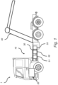
- a vehicle 1, here embodied as a heavy duty truck 1, for which an electromobility system 15 of a kind disclosed in the present invention is advantageous.
- the electromobility system 15 may as well be implemented in other types of vehicles, such as in busses, light-weight trucks, passenger cars, marine applications etc.
- the vehicle 1 is an electric vehicle, such as a full electric vehicle or a hybrid, comprising at least one electric machine 20, an energy storage system 30 comprising three energy storage devices 31, 32, 33, in the form of battery packs, the energy storage system 30 being arranged and configured to power the electric machine 20 by means of the electromobility system 15.
- the vehicle 1 comprises an auxiliary equipment 40 arranged and configured for being powered by the energy storage system 30, the auxiliary equipment 40 being e.g. a lifting equipment.
- the energy storage system 30 and the electromobility system 15 are arranged and configured to supply at least two different loads 20, 40 with electric power, the first load being the electric machine 20, and the second load being the auxiliary equipment 40.
- the energy storage system 30 may be connected to an electrical energy source via an energy transfer means (not shown), typically a cable for transferring electrical energy to the battery packs 31, 32, 33.
- the battery packs 31, 32, 33 may be charged with electrical energy.
- the vehicle 1 typically further comprises other parts of the powertrain such as transmission, drive shafts and wheels (not shown in detail).
- Fig. 2 is a schematic view of an example embodiment of the electromobility system 115 comprising an energy storage system 130, which may be implemented as the electromobility system 15 as shown in Fig. 1 .
- the electromobility system 115 comprises a primary sub-system 115A including a first battery pack arrangement 130A configured to power an electric machine 120 (as for example the electric machine 20 shown in Fig. 1 ) for propelling the vehicle, and a secondary sub-system 115B including a second battery pack arrangement 130B configured to power an auxiliary equipment 140, e.g. a vehicle bodybuilder application (as for example the lifting equipment 40 shown in Fig. 1 ).
- auxiliary equipment 140 e.g. a vehicle bodybuilder application
- the first battery pack arrangement 130A comprises a first primary battery pack 131 and a second primary battery pack 132
- the second battery pack arrangement 130B comprises a first secondary battery pack 133, however other configurations with different number of battery packs are within the scope of the invention.
- the electromobility system 115 of Fig. 2 further comprises a DC/DC-converter 150 arranged and configured to galvanically separate the primary sub-system 115A from the secondary sub-system 115B.
- the DC/DC-converter 150 is a galvanically separating DC/DC-converter 150.
- the primary sub-system 115A comprises a primary junction box 160, a charging interface 162, a traction voltage system 164 including any primary auxiliary load, and an electric machine 120 coupled to the transmission 101 of the vehicle.
- the electric machine 120 may refer to one or more electric machines and any associated control electronics.
- the primary sub-system comprises a first network of cables 168 connecting the components in the primary sub-system 115A and the DC/DC-converter 150.
- the components in the primary sub-system 115A is galvanically connected to each other, as e.g. the first battery pack arrangement 130A is galvanically connected with the electric machine 120.
- the operating voltage of the first sub-system 115A is between 500 V and 1500 V.
- the secondary sub-system 115B comprises a secondary junction box 170, and a second network of cables 172 connecting the components in the secondary sub-system 115B and the DC/DC-converter 150.
- the components in the secondary sub-system 115B is galvanically connected to each other, as e.g. the second battery pack arrangement 130B is galvanically connected with the auxiliary equipment 140.
- the operating voltage of the secondary sub-system 115B is between 60 V and 850 V.
- the electromobility system 115 is configured to, in a first state, power the electric machine 120 by the first battery pack arrangement 130A of the primary sub-system 115A independently of the secondary sub-system 115B, and is configured to power the auxiliary equipment 140 by the second battery pack arrangement 130B in the secondary sub-system 115B independently of the primary sub-system 115A. This is possible owing to the DC/DC-converter 150 separating the primary sub-system 115A and the secondary sub-system 115B.
- the electromobility system 115 is configured to, in a second state, power the auxiliary equipment 140 by the second battery pack arrangement 130B of the secondary sub-system 115B and, via the DC/DC-converter 150, the first battery pack arrangement 130A of the primary sub-system 115A. That is, in the second state, power is transferred from the primary sub-system 115A to the secondary sub-system 115B via the DC/DC-converter 150.
- the DC/DC-converter 150 may be bidirectional or unidirectional. In the latter case, the DC/DC-converter is configured to transfer power from the primary sub-system 115A to the secondary sub-system 115B.
- the second battery pack arrangement 130B may be charged by the first battery pack arrangement 130A (or the charging interface 162) of the primary sub-system 115A via the DC/DC-converter 150.
- the second battery pack arrangement 130B may be charged by the primary sub-system 115A via the DC/DC-converter 150.
- the electrical properties of the first battery pack arrangement 130A is different to the electrical properties of the second battery pack arrangement 130B.
- the electrical properties of the first primary battery pack 131 and the second primary battery pack 132 are different to the electrical properties of the first secondary battery pack 133.
- the primary and secondary battery packs have different capacitance, different cell chemistry and/or different electro-chemical properties.
- the electromobility system 115 comprise a switch 180 arranged in parallel to the DC/DC-converter 150 and being configured to galvanically connect the primary sub-system 115A with the secondary sub-system 115B in coupled state.
- the switch 180 may e.g. be an electrically-controlled switch or contactor.
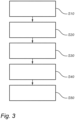
- the electromobility system referred to in the flow chart of Fig. 3 comprises a primary sub-system including at least a first battery pack arrangement configured to power an electric machine for propelling the vehicle, a secondary sub-system including at least a second battery pack arrangement configured to power an auxiliary equipment, and a DC/DC-converter arranged and configured to galvanically separate the primary sub-system from the secondary sub-system (as the embodiment shown in Fig. 2 ).
- a first step S10 the electric machine is powered by the first battery pack arrangement of the primary sub-system independently of the secondary sub-system.
- auxiliary equipment is powered by the second battery pack arrangement of the secondary sub-system independently of the primary sub-system.
- the first and second steps S10, S20 may be performed in a first state of the electromobility system. In the first state, the DC/DC-converter does not transfer any power.
- auxiliary equipment is powered by the second battery pack arrangement of the secondary sub-system and, via the DC/DC-converter, the first battery pack arrangement of the primary sub-system.
- the second battery pack arrangement is charged by means of the primary sub-system and via the DC/DC-converter, e.g. by utilising the first battery pack arrangement.
- the third step S30, and optional fourth step S40, may be performed in a second state of the electromobility system.
- the DC/DC-converter In the second state, the DC/DC-converter is transferring power from the primary sub-system to the secondary sub-system.
- step S50 power is transferred from the secondary sub-system to the primary sub-system to aid in powering a load, and/or charging the first battery pack arrangement.
- the optional fifth step S50 may be performed in third state of the electromobility system.
- the DC/DC-converter is transferring power from the secondary sub-system to the primary sub-system.
- the naming of the steps not necessarily, but might according to at least one example embodiment, relate to the order in which the steps are carried out.
- the order of the steps may be different than that explained here, and the electromobility system 115 of Fig. 2 may be configured to carry out one or several of the steps.
- one or more of the steps may be combined and carried out simultaneously.
- electromobility system 115 of Fig. 2 may be implemented as the electromobility system 15 in vehicle 1 of Fig. 1 , and may comprise a control unit having a computer program comprising program code means for performing at least some of the method steps described with reference to Fig. 3
Landscapes
- Engineering & Computer Science (AREA)
- Power Engineering (AREA)
- Transportation (AREA)
- Mechanical Engineering (AREA)
- Life Sciences & Earth Sciences (AREA)
- Sustainable Development (AREA)
- Sustainable Energy (AREA)
- Chemical & Material Sciences (AREA)
- Combustion & Propulsion (AREA)
- Electric Propulsion And Braking For Vehicles (AREA)
- Charge And Discharge Circuits For Batteries Or The Like (AREA)
Claims (14)
- Elektromobilitätssystem (15, 115) für ein Fahrzeug (1) umfassend:- ein primäres Teilsystem (115A), das mindestens eine erste Batteriepackanordnung (130A) enthält, die konfiguriert ist, um eine elektrische Maschine (20, 120) für den Antrieb des Fahrzeugs mit Energie zu versorgen,- ein sekundäres Teilsystem (115B), das ein Hochspannungs-Teilsystem ist und mindestens eine zweite Batteriepackanordnung (130B) enthält, die eine Hochspannungs-Batteriepackanordnung mit einer Spannung zwischen 60 V und 850 V ist und konfiguriert ist, um eine Hilfseinrichtung (40, 140) mit Energie zu versorgen,- einen DC/DC-Wandler (150), der angeordnet und konfiguriert ist, um das primäre Teilsystem (115A) von dem sekundären Teilsystem (115B) galvanisch zu trennen, wobei das System konfiguriert ist, umin einem ersten Zustand die elektrische Maschine (20, 120) durch die erste Batteriepackanordnung (130A) des primären Teilsystems (115A) unabhängig von dem sekundären Teilsystem (115B) mit Energie zu versorgen, und die Hilfseinrichtung (40, 140) durch die zweite Batteriepackanordnung (130B) in dem sekundären Teilsystem (115B) unabhängig von dem primären Teilsystem (115A) mit Energie zu versorgen; undin einem zweiten Zustand die Hilfseinrichtung (40, 140) durch die zweite Batteriepackanordnung (130B) des sekundären Teilsystems (115B) und die erste Batteriepackanordnung (130A) des primären Teilsystems (115A) mit Energie zu versorgen, wobei Energie von der ersten Batteriepackanordnung über den DC/DC-Wandler übertragen wird.
- Elektromobilitätssystem (15, 115) nach Anspruch 1, wobei das primäre Teilsystem (115A) konfiguriert ist, um die erste Batteriepackanordnung (130A) galvanisch mit der elektrischen Maschine (20, 120) zu verbinden, und das sekundäre Teilsystem (115B) konfiguriert ist, um die zweite Batteriepackanordnung (130B) galvanisch mit der Hilfseinrichtung (40, 140) zu verbinden.
- Elektromobilitätssystem (15, 115) nach einem der vorhergehenden Ansprüche, wobei der DC/DC-Wandler (150) ein galvanisch trennender DC/DC-Wandler ist.
- Elektromobilitätssystem (15, 115) nach einem der vorhergehenden Ansprüche, wobei der DC/DC-Wandler (150) ein unidirektionaler DC/DC-Wandler ist, der konfiguriert ist, um Energie von dem primären Teilsystem (115A) zu dem sekundären Teilsystem (115B) zu übertragen.
- Elektromobilitätssystem (15, 115) nach einem der vorhergehenden Ansprüche, wobei das System konfiguriert ist, um die zweite Batteriepackanordnung (130B) des sekundären Teilsystems (115B) durch das primäre Teilsystem (115A) über den DC/DC-Wandler (150) zu laden.
- Elektromobilitätssystem (15, 115) nach einem der vorhergehenden Ansprüche, wobei die Betriebsspannung des sekundären Teilsystems (115B) zwischen 60 V und 850 V liegt.
- Elektromobilitätssystem (15, 115) nach einem der vorhergehenden Ansprüche, wobei es sich bei der Hilfseinrichtung (40, 140) um eine Fahrzeugaufbauanwendung (40) handelt, bei der es sich um mindestens eine der folgenden handelt: Zementmischer, Müllwagenausrüstung, Kran, Hakenlift, Kipper, Kühlung (z. B. Wärmepumpe und/oder Ventilatoren), Hebebühne und Rampen für Autotransporter, Abwasser-/Schlammpumpe, Schüttgutkompressor, Leiter für Zugangsfahrzeuge und Feuerwehrausrüstung.
- Elektromobilitätssystem (15, 115) nach einem der vorhergehenden Ansprüche, wobei sich die elektrischen Eigenschaften der ersten Batteriepackanordnung (130A) von den elektrischen Eigenschaften der zweiten Batteriepackanordnung (130B) unterscheiden.
- Elektromobilitätssystem (15, 115) nach einem der vorhergehenden Ansprüche, umfassend einen Schalter (180), der parallel zum DC/DC-Wandler (150) angeordnet und konfiguriert ist, um das primäre Teilsystem (115A) mit dem sekundären Teilsystem (115B) im gekoppelten Zustand galvanisch zu verbinden.
- Verfahren zum Betreiben eines Elektromobilitätssystems in einem Fahrzeug, wobei das Elektromobilitätssystem ein primäres Teilsystem umfasst, das mindestens eine erste Batteriepackanordnung enthält, die konfiguriert ist, um eine elektrische Maschine zum Antreiben des Fahrzeugs mit Energie zu versorgen, ein sekundäres Teilsystem, das ein Hochspannungs-Teilsystem ist und mindestens eine zweite Batteriepackanordnung enthält, die eine Hochspannungs-Batteriepackanordnung mit einer Spannung zwischen 60 V und 850 V ist und konfiguriert ist, um eine Hilfseinrichtung mit Energie zu versorgen, und einen DC/DC-Wandler, der angeordnet und konfiguriert ist, um das primäre Teilsystem galvanisch von dem sekundären Teilsystem zu trennen, wobei das Verfahren umfasst:
in einem ersten Zustand, Versorgen (S10) der elektrischen Maschine durch die erste Batteriepackanordnung des primären Teilsystems unabhängig von dem sekundären Teilsystem, und Versorgen (S20) der Hilfseinrichtung durch die zweite Batteriepackanordnung des sekundären Teilsystems unabhängig von dem primären Teilsystem; und in einem zweiten Zustand, Versorgen (S30) der Hilfseinrichtung durch die zweite Batteriepackanordnung des sekundären Teilsystems und die erste Batteriepackanordnung des primären Teilsystems, wobei Energie von der ersten Batteriepackanordnung über den DC/DC-Wandler übertragen wird. - Verfahren nach Anspruch 10, das das Laden (S40) des zweiten Batteriepacks des sekundären Teilsystems durch das primäre Teilsystem über den DC/DC-Wandler umfasst.
- Computerprogramm, das Programmcodemittel zum Durchführen des Verfahrens nach einem der Ansprüche 10-11 umfasst, wenn das Programm auf einem Computer ausgeführt wird.
- Computerlesbares Medium mit einem Computerprogramm, das Programmcodemittel zum Durchführen des Verfahrens nach einem der Ansprüche 10-11 umfasst, wenn das Programm auf einem Computer ausgeführt wird.
- Fahrzeug (1) umfassend ein Elektromobilitätssystem (15, 115) nach einem der Ansprüche 1-9.
Priority Applications (3)
| Application Number | Priority Date | Filing Date | Title |
|---|---|---|---|
| EP21155124.7A EP4039523B1 (de) | 2021-02-04 | 2021-02-04 | Elektromobilitätssystem für ein fahrzeug |
| US17/649,126 US11667213B2 (en) | 2021-02-04 | 2022-01-27 | Electromobility system for a vehicle |
| CN202210107281.5A CN114851849A (zh) | 2021-02-04 | 2022-01-28 | 用于车辆的电动移动系统 |
Applications Claiming Priority (1)
| Application Number | Priority Date | Filing Date | Title |
|---|---|---|---|
| EP21155124.7A EP4039523B1 (de) | 2021-02-04 | 2021-02-04 | Elektromobilitätssystem für ein fahrzeug |
Publications (3)
| Publication Number | Publication Date |
|---|---|
| EP4039523A1 EP4039523A1 (de) | 2022-08-10 |
| EP4039523B1 true EP4039523B1 (de) | 2024-10-09 |
| EP4039523C0 EP4039523C0 (de) | 2024-10-09 |
Family
ID=74553599
Family Applications (1)
| Application Number | Title | Priority Date | Filing Date |
|---|---|---|---|
| EP21155124.7A Active EP4039523B1 (de) | 2021-02-04 | 2021-02-04 | Elektromobilitätssystem für ein fahrzeug |
Country Status (3)
| Country | Link |
|---|---|
| US (1) | US11667213B2 (de) |
| EP (1) | EP4039523B1 (de) |
| CN (1) | CN114851849A (de) |
Families Citing this family (2)
| Publication number | Priority date | Publication date | Assignee | Title |
|---|---|---|---|---|
| WO2021199118A1 (ja) * | 2020-03-30 | 2021-10-07 | 三菱電機株式会社 | エレベーター |
| EP4039523B1 (de) * | 2021-02-04 | 2024-10-09 | Volvo Truck Corporation | Elektromobilitätssystem für ein fahrzeug |
Citations (2)
| Publication number | Priority date | Publication date | Assignee | Title |
|---|---|---|---|---|
| US20160241028A1 (en) * | 2015-02-18 | 2016-08-18 | Zee.Aero Inc. | Electric vehicle power distribution system |
| US20200001720A1 (en) * | 2018-06-28 | 2020-01-02 | Ambarella, Inc. | Auxiliary power supply system for high power loads in a hybrid/electric vehicle |
Family Cites Families (33)
| Publication number | Priority date | Publication date | Assignee | Title |
|---|---|---|---|---|
| EP1458083B1 (de) | 1999-06-09 | 2012-04-04 | Lear Corporation Holding Spain S.L. | Elektrisches verteilungssystem mit doppelspannung |
| US8120308B2 (en) * | 2005-08-24 | 2012-02-21 | Ward Thomas A | Solar panel charging system for electric vehicle that charges individual batteries with direct parallel connections to solar panels |
| US20120146572A1 (en) * | 2005-08-24 | 2012-06-14 | Ward Thomas A | Solar panel charging system for electric vehicle that charges individual battery cells with direct parallel connections to solar panels and interconnected charge controllers |
| JP4417948B2 (ja) * | 2006-11-24 | 2010-02-17 | 株式会社日立製作所 | 鉄道車両の駆動制御装置 |
| JP4995005B2 (ja) * | 2007-08-24 | 2012-08-08 | 株式会社日本自動車部品総合研究所 | 車両用dcdcコンバータ装置 |
| US7960857B2 (en) * | 2008-12-02 | 2011-06-14 | General Electric Company | System and method for vehicle based uninterruptable power supply |
| JP5308268B2 (ja) * | 2009-08-05 | 2013-10-09 | 本田技研工業株式会社 | 電力供給システム |
| EP2535218B1 (de) * | 2010-02-09 | 2019-01-09 | Toyota Jidosha Kabushiki Kaisha | Stromversorgungssystem für elektrofahrzeug und steuerverfahren dafür |
| CN103492214B (zh) * | 2011-04-21 | 2015-09-30 | 丰田自动车株式会社 | 电动车辆的电源装置及其控制方法 |
| ES2692524T3 (es) * | 2011-07-26 | 2018-12-04 | Gogoro Inc. | Aparato, método y artículo para proporcionar datos de diagnóstico de vehículo |
| US9008879B2 (en) * | 2012-07-05 | 2015-04-14 | General Electric Company | System and method for operating a hybrid vehicle system |
| US20140097792A1 (en) * | 2012-10-04 | 2014-04-10 | Ut-Battelle, Llc | Electric vehicle recharging and or supplying electrical power |
| CN103029593B (zh) * | 2012-11-05 | 2015-10-28 | 荣成华泰汽车有限公司 | 电动汽车动力系统的供电控制方法和装置及供电装置 |
| KR101459900B1 (ko) * | 2013-05-07 | 2014-11-10 | 현대자동차주식회사 | 연료전지차량의 스타트 스탑 제어방법 |
| BR112016002592B1 (pt) * | 2013-08-06 | 2022-06-14 | Volvo Truck Corporation | Sistema de energia híbrido em um veículo, método para operação de sistema de energia híbrido em um veículo, e veículo compreendendo sistema de energia híbrido |
| EP3110652B1 (de) * | 2014-02-24 | 2017-12-20 | Volvo Truck Corporation | Elektrisches speichersystem für fahrzeug und verfahren zu dessen steuerung |
| WO2015192133A2 (en) * | 2014-06-13 | 2015-12-17 | University Of Maryland | An integrated dual-output grid-to-vehicle (g2v) and vehicle-to-grid (v2g) onboard charger for plug-in electric vehicles |
| US9796288B2 (en) | 2014-10-30 | 2017-10-24 | Ford Global Technologies, Llc | Bus pre-charge with vehicle power converter |
| DE102016200097A1 (de) | 2016-01-07 | 2017-07-13 | Robert Bosch Gmbh | Bordnetz |
| WO2017173420A1 (en) * | 2016-04-01 | 2017-10-05 | Faraday & Future Inc. | Electric vehicle battery management |
| US20170282747A1 (en) * | 2016-04-05 | 2017-10-05 | Ford Global Technologies, Llc | Charging system for vehicle battery |
| US10279695B2 (en) * | 2016-08-08 | 2019-05-07 | Hyundai Motor Company | Electric vehicle parallel charging method and apparatus |
| US11305663B2 (en) * | 2017-03-27 | 2022-04-19 | General Electric Company | Energy efficient hands-free electric vehicle charger for autonomous vehicles in uncontrolled environments |
| DE102018208754A1 (de) * | 2018-06-04 | 2019-12-05 | Volkswagen Aktiengesellschaft | Kraftfahrzeugbordnetz, Verfahren zum Betreiben eines derartigen Kraftfahrzeugbordnetzes sowie Sicherungsvorrichtung für ein Kraftfahrzeugbordnetz |
| DE102018221195A1 (de) * | 2018-12-07 | 2020-06-10 | Robert Bosch Gmbh | Bidirektionaler DC/DC-Wandler und Verfahren zum Betreiben des DC/DC Wandlers |
| EP3942662A1 (de) * | 2019-03-22 | 2022-01-26 | Eaton Intelligent Power Limited | Leistungsverteilung und schaltungsschutz für eine mobile anwendung mit einem hocheffizienten wechselrichter |
| JP2021191231A (ja) * | 2020-06-04 | 2021-12-13 | トランスポーテーション アイピー ホールディングス,エルエルシー | 電気供給システム |
| US11424640B2 (en) * | 2020-09-25 | 2022-08-23 | Apple Inc. | Integrated high-voltage-low-voltage DC-DC converter and charger with active filter |
| GB2599386B (en) * | 2020-09-30 | 2024-06-05 | Jaguar Land Rover Ltd | Electrical vehicle circuitry |
| GB2599388B (en) * | 2020-09-30 | 2024-11-27 | Jaguar Land Rover Ltd | Electrical vehicle circuitry |
| CN114512977A (zh) * | 2020-11-17 | 2022-05-17 | 台达电子企业管理(上海)有限公司 | 功率变换系统和控制方法 |
| EP4039523B1 (de) * | 2021-02-04 | 2024-10-09 | Volvo Truck Corporation | Elektromobilitätssystem für ein fahrzeug |
| EP4046847A1 (de) * | 2021-02-17 | 2022-08-24 | Volvo Truck Corporation | System und verfahren zur handhabung des aus- und einkuppelns zwischen einem zapfwellensystem und einem traktionssystem in einem zumindest teilweise elektrisch betriebenen fahrzeug |
-
2021
- 2021-02-04 EP EP21155124.7A patent/EP4039523B1/de active Active
-
2022
- 2022-01-27 US US17/649,126 patent/US11667213B2/en active Active
- 2022-01-28 CN CN202210107281.5A patent/CN114851849A/zh active Pending
Patent Citations (2)
| Publication number | Priority date | Publication date | Assignee | Title |
|---|---|---|---|---|
| US20160241028A1 (en) * | 2015-02-18 | 2016-08-18 | Zee.Aero Inc. | Electric vehicle power distribution system |
| US20200001720A1 (en) * | 2018-06-28 | 2020-01-02 | Ambarella, Inc. | Auxiliary power supply system for high power loads in a hybrid/electric vehicle |
Also Published As
| Publication number | Publication date |
|---|---|
| US20220242275A1 (en) | 2022-08-04 |
| US11667213B2 (en) | 2023-06-06 |
| EP4039523A1 (de) | 2022-08-10 |
| CN114851849A (zh) | 2022-08-05 |
| EP4039523C0 (de) | 2024-10-09 |
Similar Documents
| Publication | Publication Date | Title |
|---|---|---|
| CN109808497B (zh) | 燃料电池车辆系统及其控制方法 | |
| US11014451B2 (en) | Reconfigurable electrical power conversion system | |
| EP2413452B1 (de) | Bidirektionaler polyphasen-multimodewandler, der hochsetz- und tiefsetz-hochsetz-modi umfasst | |
| KR102419697B1 (ko) | 자동차용 저장 배터리 충전 장치, 온보드 저장 배터리 충전 장치를 동작시키는 방법, 고전압 차량 전기 시스템, 및 저장 배터리 충전 장치의 사용 | |
| US10081257B2 (en) | Method and apparatus for charging multiple energy storage devices | |
| CN101357593B (zh) | 使用双端逆变器系统用整流器对能源充电 | |
| EP3030440B1 (de) | Hybridfahrzeug | |
| CN110549890B (zh) | Dc/dc转换单元 | |
| US10118495B2 (en) | Vehicle power distribution having relay with integrated voltage converter | |
| US8378623B2 (en) | Apparatus and method for charging an electric vehicle | |
| US12409758B2 (en) | Control unit for an electric power transmission system | |
| CN115158015B (zh) | 一种功率转换装置和电动汽车 | |
| CN108215878A (zh) | 用于对电动车辆直流快速充电的车辆充电系统 | |
| US20190337394A1 (en) | Vehicle exportable power | |
| CN102386666A (zh) | 用于对插电式混合动力车再充电的系统及控制方法 | |
| US11667213B2 (en) | Electromobility system for a vehicle | |
| WO2024017137A1 (en) | A high-voltage battery pack | |
| US11996534B2 (en) | Electric power module system | |
| US12266952B2 (en) | Method for reducing wear of an energy storage device | |
| WO2021001048A1 (en) | An electric power module system | |
| CN120710378A (zh) | 转换控制装置及车辆 | |
| CN113135153A (zh) | 非车载逆变器车辆接口系统 |
Legal Events
| Date | Code | Title | Description |
|---|---|---|---|
| PUAI | Public reference made under article 153(3) epc to a published international application that has entered the european phase |
Free format text: ORIGINAL CODE: 0009012 |
|
| STAA | Information on the status of an ep patent application or granted ep patent |
Free format text: STATUS: THE APPLICATION HAS BEEN PUBLISHED |
|
| AK | Designated contracting states |
Kind code of ref document: A1 Designated state(s): AL AT BE BG CH CY CZ DE DK EE ES FI FR GB GR HR HU IE IS IT LI LT LU LV MC MK MT NL NO PL PT RO RS SE SI SK SM TR |
|
| STAA | Information on the status of an ep patent application or granted ep patent |
Free format text: STATUS: REQUEST FOR EXAMINATION WAS MADE |
|
| 17P | Request for examination filed |
Effective date: 20230118 |
|
| RBV | Designated contracting states (corrected) |
Designated state(s): AL AT BE BG CH CY CZ DE DK EE ES FI FR GB GR HR HU IE IS IT LI LT LU LV MC MK MT NL NO PL PT RO RS SE SI SK SM TR |
|
| STAA | Information on the status of an ep patent application or granted ep patent |
Free format text: STATUS: EXAMINATION IS IN PROGRESS |
|
| 17Q | First examination report despatched |
Effective date: 20230823 |
|
| RIC1 | Information provided on ipc code assigned before grant |
Ipc: H02M 3/335 20060101ALI20240322BHEP Ipc: H02J 1/10 20060101ALI20240322BHEP Ipc: H02M 1/10 20060101ALI20240322BHEP Ipc: B60W 30/188 20120101ALI20240322BHEP Ipc: B60K 25/00 20060101ALI20240322BHEP Ipc: H02J 7/34 20060101ALI20240322BHEP Ipc: B60K 1/00 20060101ALI20240322BHEP Ipc: B60K 1/04 20190101ALI20240322BHEP Ipc: B60K 6/28 20071001ALI20240322BHEP Ipc: B60L 58/20 20190101ALI20240322BHEP Ipc: B60L 1/00 20060101AFI20240322BHEP |
|
| GRAP | Despatch of communication of intention to grant a patent |
Free format text: ORIGINAL CODE: EPIDOSNIGR1 |
|
| STAA | Information on the status of an ep patent application or granted ep patent |
Free format text: STATUS: GRANT OF PATENT IS INTENDED |
|
| INTG | Intention to grant announced |
Effective date: 20240507 |
|
| GRAS | Grant fee paid |
Free format text: ORIGINAL CODE: EPIDOSNIGR3 |
|
| GRAA | (expected) grant |
Free format text: ORIGINAL CODE: 0009210 |
|
| STAA | Information on the status of an ep patent application or granted ep patent |
Free format text: STATUS: THE PATENT HAS BEEN GRANTED |
|
| AK | Designated contracting states |
Kind code of ref document: B1 Designated state(s): AL AT BE BG CH CY CZ DE DK EE ES FI FR GB GR HR HU IE IS IT LI LT LU LV MC MK MT NL NO PL PT RO RS SE SI SK SM TR |
|
| REG | Reference to a national code |
Ref country code: CH Ref legal event code: EP |
|
| REG | Reference to a national code |
Ref country code: DE Ref legal event code: R096 Ref document number: 602021019761 Country of ref document: DE |
|
| REG | Reference to a national code |
Ref country code: IE Ref legal event code: FG4D |
|
| U01 | Request for unitary effect filed |
Effective date: 20241029 |
|
| U07 | Unitary effect registered |
Designated state(s): AT BE BG DE DK EE FI FR IT LT LU LV MT NL PT RO SE SI Effective date: 20241111 |
|
| U20 | Renewal fee for the european patent with unitary effect paid |
Year of fee payment: 5 Effective date: 20250224 |
|
| PG25 | Lapsed in a contracting state [announced via postgrant information from national office to epo] |
Ref country code: IS Free format text: LAPSE BECAUSE OF FAILURE TO SUBMIT A TRANSLATION OF THE DESCRIPTION OR TO PAY THE FEE WITHIN THE PRESCRIBED TIME-LIMIT Effective date: 20250209 Ref country code: HR Free format text: LAPSE BECAUSE OF FAILURE TO SUBMIT A TRANSLATION OF THE DESCRIPTION OR TO PAY THE FEE WITHIN THE PRESCRIBED TIME-LIMIT Effective date: 20241009 |
|
| PG25 | Lapsed in a contracting state [announced via postgrant information from national office to epo] |
Ref country code: ES Free format text: LAPSE BECAUSE OF FAILURE TO SUBMIT A TRANSLATION OF THE DESCRIPTION OR TO PAY THE FEE WITHIN THE PRESCRIBED TIME-LIMIT Effective date: 20241009 |
|
| PG25 | Lapsed in a contracting state [announced via postgrant information from national office to epo] |
Ref country code: NO Free format text: LAPSE BECAUSE OF FAILURE TO SUBMIT A TRANSLATION OF THE DESCRIPTION OR TO PAY THE FEE WITHIN THE PRESCRIBED TIME-LIMIT Effective date: 20250109 |
|
| PG25 | Lapsed in a contracting state [announced via postgrant information from national office to epo] |
Ref country code: GR Free format text: LAPSE BECAUSE OF FAILURE TO SUBMIT A TRANSLATION OF THE DESCRIPTION OR TO PAY THE FEE WITHIN THE PRESCRIBED TIME-LIMIT Effective date: 20250110 |
|
| PG25 | Lapsed in a contracting state [announced via postgrant information from national office to epo] |
Ref country code: PL Free format text: LAPSE BECAUSE OF FAILURE TO SUBMIT A TRANSLATION OF THE DESCRIPTION OR TO PAY THE FEE WITHIN THE PRESCRIBED TIME-LIMIT Effective date: 20241009 |
|
| PG25 | Lapsed in a contracting state [announced via postgrant information from national office to epo] |
Ref country code: RS Free format text: LAPSE BECAUSE OF FAILURE TO SUBMIT A TRANSLATION OF THE DESCRIPTION OR TO PAY THE FEE WITHIN THE PRESCRIBED TIME-LIMIT Effective date: 20250109 |
|
| PG25 | Lapsed in a contracting state [announced via postgrant information from national office to epo] |
Ref country code: SM Free format text: LAPSE BECAUSE OF FAILURE TO SUBMIT A TRANSLATION OF THE DESCRIPTION OR TO PAY THE FEE WITHIN THE PRESCRIBED TIME-LIMIT Effective date: 20241009 |
|
| PG25 | Lapsed in a contracting state [announced via postgrant information from national office to epo] |
Ref country code: SK Free format text: LAPSE BECAUSE OF FAILURE TO SUBMIT A TRANSLATION OF THE DESCRIPTION OR TO PAY THE FEE WITHIN THE PRESCRIBED TIME-LIMIT Effective date: 20241009 |
|
| PG25 | Lapsed in a contracting state [announced via postgrant information from national office to epo] |
Ref country code: CZ Free format text: LAPSE BECAUSE OF FAILURE TO SUBMIT A TRANSLATION OF THE DESCRIPTION OR TO PAY THE FEE WITHIN THE PRESCRIBED TIME-LIMIT Effective date: 20241009 |
|
| PLBE | No opposition filed within time limit |
Free format text: ORIGINAL CODE: 0009261 |
|
| STAA | Information on the status of an ep patent application or granted ep patent |
Free format text: STATUS: NO OPPOSITION FILED WITHIN TIME LIMIT |
|
| PG25 | Lapsed in a contracting state [announced via postgrant information from national office to epo] |
Ref country code: MC Free format text: LAPSE BECAUSE OF FAILURE TO SUBMIT A TRANSLATION OF THE DESCRIPTION OR TO PAY THE FEE WITHIN THE PRESCRIBED TIME-LIMIT Effective date: 20241009 |
|
| 26N | No opposition filed |
Effective date: 20250710 |
|
| REG | Reference to a national code |
Ref country code: CH Ref legal event code: PL |
|
| PG25 | Lapsed in a contracting state [announced via postgrant information from national office to epo] |
Ref country code: CH Free format text: LAPSE BECAUSE OF NON-PAYMENT OF DUE FEES Effective date: 20250228 |
|
| GBPC | Gb: european patent ceased through non-payment of renewal fee |
Effective date: 20250204 |
|
| PG25 | Lapsed in a contracting state [announced via postgrant information from national office to epo] |
Ref country code: GB Free format text: LAPSE BECAUSE OF NON-PAYMENT OF DUE FEES Effective date: 20250204 |
|
| PG25 | Lapsed in a contracting state [announced via postgrant information from national office to epo] |
Ref country code: IE Free format text: LAPSE BECAUSE OF NON-PAYMENT OF DUE FEES Effective date: 20250204 |
|
| U20 | Renewal fee for the european patent with unitary effect paid |
Year of fee payment: 6 Effective date: 20260224 |