EP4039567B1 - Jambe mécanique à double mode de jambe de roue et robot - Google Patents
Jambe mécanique à double mode de jambe de roue et robot Download PDFInfo
- Publication number
- EP4039567B1 EP4039567B1 EP21838701.7A EP21838701A EP4039567B1 EP 4039567 B1 EP4039567 B1 EP 4039567B1 EP 21838701 A EP21838701 A EP 21838701A EP 4039567 B1 EP4039567 B1 EP 4039567B1
- Authority
- EP
- European Patent Office
- Prior art keywords
- calf
- wheel
- unit
- pin
- rotary shaft
- Prior art date
- Legal status (The legal status is an assumption and is not a legal conclusion. Google has not performed a legal analysis and makes no representation as to the accuracy of the status listed.)
- Active
Links
Images




Classifications
-
- B—PERFORMING OPERATIONS; TRANSPORTING
- B62—LAND VEHICLES FOR TRAVELLING OTHERWISE THAN ON RAILS
- B62D—MOTOR VEHICLES; TRAILERS
- B62D57/00—Vehicles characterised by having other propulsion or other ground- engaging means than wheels or endless track, alone or in addition to wheels or endless track
- B62D57/02—Vehicles characterised by having other propulsion or other ground- engaging means than wheels or endless track, alone or in addition to wheels or endless track with ground-engaging propulsion means, e.g. walking members
- B62D57/028—Vehicles characterised by having other propulsion or other ground- engaging means than wheels or endless track, alone or in addition to wheels or endless track with ground-engaging propulsion means, e.g. walking members having wheels and mechanical legs
-
- B—PERFORMING OPERATIONS; TRANSPORTING
- B62—LAND VEHICLES FOR TRAVELLING OTHERWISE THAN ON RAILS
- B62D—MOTOR VEHICLES; TRAILERS
- B62D57/00—Vehicles characterised by having other propulsion or other ground- engaging means than wheels or endless track, alone or in addition to wheels or endless track
- B62D57/02—Vehicles characterised by having other propulsion or other ground- engaging means than wheels or endless track, alone or in addition to wheels or endless track with ground-engaging propulsion means, e.g. walking members
- B62D57/032—Vehicles characterised by having other propulsion or other ground- engaging means than wheels or endless track, alone or in addition to wheels or endless track with ground-engaging propulsion means, e.g. walking members with alternately or sequentially lifted supporting base and legs; with alternately or sequentially lifted feet or skid
Definitions
- This application relates to the field of robots, and in particular, to a wheel-footed bimodal mechanical leg and a robot.
- the robot refers to a robot having both footed and wheeled movement modes.
- a common robot is a robot with two, three, four, or six mechanical legs.
- a quadruped robot is provided in the related art.
- Four mechanical legs are mounted on the quadruped robot. Traveling wheels are mounted at ends of calves of the four mechanical legs, to enable the quadruped robot to have both footed and wheeled movement modes.
- the end of the calf of the foregoing mechanical leg is a wheeled structure, the end of the calf has poor grip and balance.
- CN 101219683 B provides a wheel-footed dual-purpose mobile robot, which adopts footed and wheeled movement modes.
- CN 110304167 A provides a wheel-leg composite structure and a wheel-leg composite four-foot bio-robot.
- Embodiments of this application provide a wheel-footed bimodal mechanical leg and a robot.
- the technical solutions are as follows: According to an aspect of this application, a wheel-footed bimodal mechanical leg is provided according to claim 1. Optional features are set out in dependent claims 2 to 12.
- a robot is provided according to claim 13.
- the traveling wheel is arranged at a joint between the thigh unit and the calf unit.
- the calf unit In the footed mode, the calf unit is fixedly connected to the rotary shaft by the locking component, and the calf unit is driven by the rotary shaft to implement footed traveling. Because the traveling wheel is located at the j oint between the thigh unit and the calf unit and do not touch the ground, the calf unit may maintain better grip and balance.
- all or some of the calf units are rotatably connected to the rotary shafts. The traveling wheels on the rotary shafts implement wheeled traveling.
- the length of the thigh unit can ensure a ground clearance of the body part, the passing ability and passing speed of the robot in the wheeled mode are improved.
- the foregoing robot features a compact structure, high dexterity, and a light weight.
- Environmental adaptability of the robot may be enhanced to a large extent by flexibly switching between the wheeled mode and the footed mode.
- Embodiments of this application provide a robot.
- the robot can travel in a wheeled mode or a footed mode.
- FIG. 1 is a schematic diagram of a robot 10 according to an exemplary embodiment of this application.
- the robot 10 includes: a body part 12 and n wheel-footed bimodal mechanical legs 14 connected to the body part 12, where n is a positive integer not less than 2.
- the wheel-footed bimodal mechanical leg 14 includes a driving apparatus 1, a thigh unit 2, and a calf unit 3.
- a joint end of the thigh unit 2 is hingedly connected to a joint end of the calf unit 3 by a rotary shaft 4.
- the rotary shaft 4 is transmission-connected to the traveling wheel 5.
- the calf unit 3 includes a locking component for locking or unlocking relative positions of the calf unit 3 and the rotary shaft 4.
- the locking component locks the relative positions of the calf unit 3 and the rotary shaft 4
- the calf unit 3 is fixedly connected to the rotary shaft 4.
- the movement of the calf unit 3 is controlled by the rotation of the rotary shaft 4 and switches from the wheeled mode to the footed mode.
- the locking component unlocks the relative positions of the calf unit 3 and the rotary shaft 4
- the movement of the calf unit 3 is not controlled by the rotation of the rotary shaft 4 and switches from the footed mode to the wheeled mode.
- the calf units 3 and the rotary shafts 4 in the n wheel-footed bimodal mechanical legs 14 are fixedly connected to each other.
- the robot 10 drives, through the rotary shafts 4, the calf units 3 to travel in a footed movement mode.
- the rotary shaft 4 drives the traveling wheel 5 to rotate forward
- the calf unit 3 is also driven to rotate forward.
- the rotary shaft 4 drives the traveling wheel 5 to rotate backward
- the calf unit 3 is also driven to rotate backward.
- the footed movement can be implemented by repeatedly performing the foregoing process.
- the calf units 3 and the rotary shafts 4 in at least two wheel-footed bimodal mechanical legs 14 are rotatably connected to each other.
- the rotary shaft 4 and the traveling wheel 5 may freely rotate relative to the calf unit 3. Therefore, the rotary shaft 4 drives the traveling wheel 5 to rotate forward, thereby implementing the wheeled movement.
- the rotary shaft 4 in a process of switching from the footed mode to the wheeled mode, because the robot 10 touches the ground using an end of the calf unit 3 in the footed mode, the rotary shaft 4 first drives the calf unit 3 to rotate in a first direction of approaching the thigh unit 2. After the traveling wheel 5 touches the ground, the rotary shaft 4 continues to drive the calf unit 3 toward the thigh unit 2 for folding them together. After the calf unit 3 and the thigh unit 2 are folded together, the end of the calf unit 3 is in an off-ground state. The locking component unlocks the relative positions of the calf unit 3 and the rotary shaft 4. The footed mode is switched to the wheeled mode. Subsequently, in the wheeled mode, the rotary shaft 4 drives the traveling wheel 5 to perform the wheeled movement forward or backward.
- the rotary shaft 4 in a process of switching from the wheeled mode to the footed mode, because the robot 10 touches the ground using the traveling wheel 5 to the wheeled mode, the rotary shaft 4 first drives the calf unit 3 to rotate in a second direction away from the thigh unit 2. After the end of the calf unit 3 touches the ground, the rotary shaft 4 continues to drive the calf unit 3 to rotate in the second direction, thereby supporting the body part 12 of the robot 10 to rise, and then the traveling wheel 5 is in an off-ground state.
- the locking component locks the relative positions of the calf unit 3 and the rotary shaft 4. In this case, the wheeled mode is switched to the footed mode. Subsequently, in the footed mode, the rotary shaft 4 drives the calf unit 3 to perform the footed movement forward or backward.
- the traveling wheel is arranged at a joint between the thigh unit and the calf unit.
- the calf unit In the footed mode, the calf unit is fixedly connected to the rotary shaft, and the calf unit is driven by the rotary shaft to implement footed traveling. Because the traveling wheel is located at the joint between the thigh unit and the calf unit and do not touch the ground, the calf unit may maintain better grip and balance.
- all or some of the calf units are rotatably connected to the rotary shafts. The traveling wheels on the rotary shafts implement wheeled traveling. Because the length of the thigh unit can ensure a ground clearance of the body part, the passing ability of the robot in the wheeled mode is improved.
- the number of the wheel-footed bimodal mechanical legs 14 of the robot 10 may be two, three, four, six, etc., and the present application does not limit the number of the wheel-footed bimodal mechanical legs 14.
- FIG. 2 shows a three-dimensional view of a robot 10 according to another exemplary embodiment of this application.
- the robot 10 includes: a body part 12, and 4 wheel-footed bimodal mechanical legs 14 connected to the body part 12.
- the wheel-footed bimodal mechanical leg 14 includes a driving apparatus 1, a thigh unit 2, and a calf unit 3.
- the driving apparatus 1 includes at least one of a first thigh driving apparatus 151, a second thigh driving apparatus 152, or a calf driving apparatus 153.
- the first thigh driving apparatus 151, the second thigh driving apparatus 152, and the calf driving apparatus 153 constitute a combined driving apparatus.
- the calf driving apparatus 153 is further connected to a root end 201 of the thigh unit 2.
- a joint end 202 of the thigh unit 2 is connected to a joint end 301 of the calf unit 3.
- An auxiliary wheel 9 is disposed on a side surface of the calf unit 3 close to the ground (referred to as a near-ground side).
- a sole portion 8 is disposed at an end 22 of the calf unit 3.
- the first thigh driving apparatus 151, the second thigh driving apparatus 152, and the calf driving apparatus 153 are all motors.
- Each motor includes a stator portion and a rotor portion. The rotor portion can rotate relative to the stator portion.
- FIG. 4 is a top view of the robot 10
- FIG. 5 is a side view of the robot 10.
- the first thigh driving apparatus 151 is configured to drive the thigh unit 2 to rotate along two sides of the body part 12.
- a first stator portion of the first thigh driving apparatus 151 is connected to the body part 12.
- a first rotor portion of the first thigh driving apparatus 151 is connected to a side surface of a second stator portion of the second thigh driving apparatus 152.
- a central axis of a first rotor portion is parallel to a central axis of the body part 12.
- the second thigh driving apparatus 152 is configured to drive the thigh unit 2 to swing along the front/rear of the body part 12.
- a second rotor portion of the second thigh driving apparatus 152 is connected to a third stator portion of the calf driving apparatus 153.
- the second rotor portion faces an outer side of the body part 12.
- the second stator portion faces an inner side of the body part 12.
- a central axis of the second rotor portion is perpendicular to the central axis of the body part 12.
- the third stator portion of the calf driving apparatus 153 is connected to the root end 201 of the thigh unit 2.
- a third rotor portion of the calf driving apparatus 153 is connected to the rotary shaft 4 by a transmission apparatus.
- a central axis of the third rotor portion coincides with or is parallel to the central axis of the second rotor portion.
- the robot 10 has at least three movement modes: a footed mode, a first wheeled mode, and a second wheeled mode.
- the calf unit 3 and the rotary shaft 4 in each wheel-footed bimodal mechanical leg 14 are fixedly connected to each other.
- the second rotor portion of the second thigh driving apparatus 152 drives the thigh unit 2 to swing along the front/rear of the body part 12.
- the third rotor portion of the calf driving apparatus 153 rotates, and drives the traveling wheel 5 and the calf unit 3 through the rotary shaft 4 to travel in the footed movement mode.
- the calf driving apparatus 153 drives the traveling wheel 5 through the rotary shaft 4 to rotate forward
- the calf unit 3 is also driven to rotate forward.
- the calf driving apparatus 153 drives the traveling wheel 5 through the rotary shaft 4 to rotate backward
- the calf unit 3 is also driven to rotate backward.
- the footed movement can be implemented by repeatedly performing the foregoing process.
- the calf unit 3 and the rotary shaft 4 in each wheel-footed bimodal mechanical leg 14 are rotatably connected to each other.
- the calf driving apparatus 153 drives the traveling wheel 5 through the rotary shaft 4 to rotate without driving the calf unit 3 to rotate.
- the calf unit 3 may include a first magnetic component 91 thereon, and the thigh unit 2 may include a second magnetic component 92 thereon.
- One of the first magnetic component 91 and the second magnetic component 92 is a magnet, and the other of the first magnetic component 91 and the second magnetic component 92 is a magnet or an iron block.
- the first magnetic component 91 may be attracted to the second magnetic component 92.
- the calf unit 3 and the thigh unit 2 are in a contracted and closed state, the calf unit 3 and the thigh unit 2 are fixed by a magnetic force between the magnetic components, thereby reducing interference of the calf unit 3 in the first wheeled mode.
- the end of the calf unit 3 faces upward, so that the body part 12 has a relatively appropriate ground clearance, less wind resistance, better passing ability, and a higher passing speed.
- the contracted and closed state means that after the calf unit 3 is contracted in a direction of the thigh unit 2, the calf unit 3 and the thigh unit 2 are in a state of being close to each other and folded together.
- An auxiliary wheel 9 is further disposed on a near-ground side of the calf unit 3.
- the calf units 3 and the rotary shafts 4 in m wheel-footed bimodal mechanical legs 14 located at a same end 02 (a front end or a rear end) of the body part 12 are rotatably connected to each other.
- the calf units 3 and the rotary shafts 4 in the remaining n-m wheel-footed bimodal mechanical legs 14 located at an other end 04 of the body part 12 are fixedly connected to each other.
- the calf units 3 and the rotary shafts 4 in two wheel-footed bimodal mechanical legs 14 located at the rear end 02 of the body part 12 are rotatably connected to each other.
- the calf units 3 and the rotary shafts 4 in two wheel-footed bimodal mechanical legs 14 located at the front end 04 of the body part 12 are fixedly connected to each other.
- the robot 10 may be supported by only 2 mechanical legs to move forward or backward in the wheeled mode.
- the auxiliary wheels 9 provide support and the ability to assist rolling during wheeled forward or backward movement.
- the two traveling wheels 5 move under the driving of a driving force.
- the two auxiliary wheels 9 move with the movement of the traveling wheels 5.
- the two traveling wheels 5 and the two auxiliary wheels 9 provide four force application points to ensure the stability of the robot 10 during traveling.
- the calf units 3 and the thigh units 2 in the two wheel-footed bimodal mechanical legs 14 located at the rear end 02 of the body part 12 may be attracted to each other through the magnetic components.
- the robot 10 performs wheeled forward or backward movement through the two wheel-footed bimodal mechanical legs 14 located at the rear end 02 of the body part 12. During the wheeled forward or backward movement, the robot 10 may further perform other actions, such as opening a door, transporting an object, or photographing, etc., through the two wheel-footed bimodal mechanical legs 14 located at the front end 04 of the body part 12.
- the calf unit 3 and the rotary shaft 4 may be switched between a fixed connection and a rotatable connection, or, in other words, switched between a fixed state and a rotatable state or switched between the footed mode and the wheeled mode.
- the calf unit 3 includes a locking component 7 (or a pin component 7) therein. The locking component 7 is configured to implement the switching between the fixed connection and the rotatable connection.
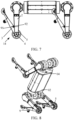
- FIG. 9 is a schematic diagram of a wheel-footed bimodal mechanical leg 14 according to an exemplary embodiment of this application.
- the mechanical leg includes a driving apparatus 1, a thigh unit 2, and a calf unit 3.
- a root end 201 of the thigh unit 2 is connected to the driving apparatus 1.
- a joint end 202 of the thigh unit 2 is hingedly connected (e.g., hinged) to a joint end 301 of the calf unit 3 by a rotary shaft 4.
- the rotary shaft 4 is transmission-connected to a traveling wheel 5.
- the driving apparatus 1 is connected to the traveling wheel 5 by a transmission apparatus 6.
- a traveling wheel 5 is fixed on at least one position of two ends or a middle position of the rotary shaft 4. There may be one or more traveling wheels 5.
- the calf unit 3 includes a locking component (not shown in FIG. 9 , refer to FIG. 10 or FIG. 15 ).
- the calf unit 3 and the traveling wheel 5 are locked to each other.
- the calf unit 3 is fixedly connected to the rotary shaft 4 by the traveling wheel 5, so that the driving apparatus 1 drives the traveling wheel 5 and the calf unit 3 through the rotary shaft 4 to travel in the footed movement mode.
- the calf unit 3 and the traveling wheel 5 are unlocked from each other.
- the calf unit 3 is rotatably connected to the rotary shaft 4, so that the driving apparatus 1 drives the traveling wheel 5 through the rotary shaft 4 to travel in the wheeled movement mode without driving the calf unit 3 to move.
- the working principles of the foregoing wheel-footed bimodal mechanical leg 14 include: When the locking component is in the locked state, the calf unit 3 is fixedly connected to the rotary shaft 4 through the traveling wheel 5. When the driving apparatus 1 drives the traveling wheel 5 through the rotary shaft 4 to rotate forward, the calf unit 3 is also driven to rotate forward. When the driving apparatus 1 drives the traveling wheel 5 through the rotary shaft 4 to rotate backward, the calf unit 3 is also driven to rotate backward.
- the footed movement can be implemented by repeatedly performing the foregoing process.
- the calf unit 3 When the locking component is in the unlocked state, the calf unit 3 is rotatably connected to the rotary shaft 4. That is, the rotary shaft 4 and the traveling wheel 5 can freely rotate relative to the calf unit 3.
- the driving apparatus 1 drives the traveling wheel 5 through the rotary shaft 4 to rotate forward, thereby implementing the wheeled movement.
- the locking component is arranged in the calf unit, so that the calf unit and the traveling wheel are locked to each other when the locking component is in the locked state.
- the calf unit is fixedly connected to the rotary shaft by the traveling wheel, so that the driving apparatus drives the traveling wheel through the rotary shaft to drive the calf unit to travel in the footed mode.
- the calf unit and the traveling wheel are unlocked from each other.
- the calf unit is rotatably connected to the rotary shaft, so that the driving apparatus drives the traveling wheel through the rotary shaft to travel in the wheeled mode.
- only one driving apparatus is needed to implement the wheel-footed bimodal mechanical leg, which simplifies the structure of the mechanical leg, and is beneficial to the miniaturization and portability of the mechanical leg.
- the locking component 7 includes a flat pin, and a pin hole is designed on the traveling wheel 5, as shown in FIG. 10 .
- the locking component 7 includes a double-shaft pin.
- the pin hole is designed on the rotary shaft 4, as shown in FIG. 15 .
- the pin hole is designed on the traveling wheel 5.
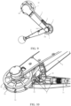
- FIG. 10 is a structural diagram of a locking component 7 according to an exemplary embodiment of this application.
- the locking component 7 is configured for locking or unlocking between the calf unit 3 and traveling wheel 5.
- the locking component 7 includes a linear motor 71 and a flat pin 72.
- the linear motor 71 is a transmission apparatus that converts electrical energy into mechanical energy for a linear movement.
- the calf unit 3 includes a motor fixing base 33 therein.
- the motor fixing base 33 fixes the linear motor 71 to an inner wall of the calf unit 3.
- the flat pin 72 is fixed to an output end of the linear motor 71.
- the traveling wheel 5 includes at least one pin groove 74 thereon.
- the flat pin 72 is inserted into the pin groove 74 or pulled out from the pin groove 74 under the driving of the linear motor 71.
- the locking component 7 is in the locked state when the flat pin 72 is inserted into the pin groove 74.
- the calf unit 3 and the traveling wheel 5 are locked to each other.
- the calf unit 3 is fixedly connected to the rotary shaft 4 by the traveling wheel 5, as shown in FIG. 11 .
- the rotary shaft 4 drives the traveling wheel 5 to rotate, the calf unit 3 also rotates with the traveling wheel 5.
- the locking component 7 is in the unlocked state.
- the calf unit 3 and the traveling wheel 5 are unlocked from each other.
- the calf unit 3 is rotatably connected to the rotary shaft 4.
- the rotary shaft 4 drives the traveling wheel 5 to rotate, the calf unit 3 does not rotate with the traveling wheel 5.
- each pin groove 74 is distributed along a radial direction of the traveling wheel 5. That is, the traveling wheel 5 includes at least two pin grooves 74 distributed in the radial direction thereon. The at least two pin grooves 74 may be uniformly distributed or non-uniformly distributed.
- the traveling wheel 5 includes at least one traveling wheel.
- An example in which the traveling wheel includes a first traveling wheel 51 and a second traveling wheel 52 is used for description in this embodiment.
- the first traveling wheel 51 and the second traveling wheel 52 are relatively fixed.
- the pin groove 74 is formed on a first wheel surface of the first traveling wheel 51 facing the second traveling wheel 52.
- the pin groove 74 is formed on a second wheel surface of the second traveling wheel 52 facing the first traveling wheel 51.
- the number and grooving positions of the pin grooves 74 on the first wheel surface and the second wheel surface are the same.
- the locking component provided in this embodiment is locked by inserting the flat pin 72 into the pin groove 74 of the traveling wheel 5 under the driving of the linear motor 71, and is unlocked by pulling the flat pin 72 out from the pin groove 74 of the traveling wheel 5 under the driving the linear motor 71.
- the linear motor 71 is hidden inside the calf unit 3, so that the structure is relatively simple, which can better ensure the miniaturization and portability of the calf unit 3.
- FIG. 12 and FIG. 13 are respectively exploded views of a wheel-footed bimodal mechanical leg 14 according to another exemplary embodiment of this application from two viewing angles.
- the wheel-footed bimodal mechanical leg 14 includes at least a driving apparatus 1, a thigh unit 2, a calf unit 3, a rotary shaft 4, a traveling wheel 5, a transmission apparatus 6, and a locking component 7.
- the driving apparatus 1 includes a third stator portion 531 and a third rotor portion 532.
- the third stator portion 531 is configured to provide a rotational driving force.
- a transmission wheel 533 is fixed to an output end of the third rotor portion 532.
- the transmission wheel 533 is connected to the transmission apparatus 6.
- the transmission apparatus 6 is a belt or a chain. An example in which the transmission apparatus 6 is the belt is used for description in this embodiment.
- a gear is further formed on a surface of the transmission wheel 533 to increase a transmission force between the transmission wheel 533 and the belt.
- a root end 201 of the thigh unit 2 is fixed to the third stator portion 531.
- a joint end 202 of the thigh unit 2 is hingedly connected to a joint end 301 of the calf unit 3 by the rotary shaft 4.
- the thigh unit 2 includes a first thigh portion 220 and a second thigh portion 240 that are detachably connected to each other.
- the first thigh portion 220 and the second thigh portion 240 are in a plugged connection, or are connected by using a screw or a nut.
- the first thigh portion 220 and the second thigh portion 240 enclose a casing portion of the thigh unit 2, and form an inner accommodation cavity of the thigh unit 2.
- the first thigh portion 220 is located on a first side of the transmission apparatus 6.
- the second thigh portion 240 is located on a second side of the transmission apparatus 6.
- the first thigh portion 220 is located on an outer side of the transmission apparatus 6.
- the second thigh portion 240 is located on an inner side of the transmission apparatus 6.
- the thigh unit 2 further includes a belt pressing apparatus 23 inside. The belt pressing apparatus 23 is in pressing contact with an outer surface of the belt.
- the calf unit 3 includes a first calf portion 320 and a second calf portion 340 that are detachably connected to each other.
- the first calf portion 320 and the second calf portion 340 are in plugged connection, or are connected by using a screw or a nut.
- the first calf portion 320 and the second calf portion 340 enclose a casing portion of the calf unit 3, and form an inner accommodation cavity of the calf unit 3.
- the first calf portion 320 is located on a first side of the transmission apparatus 6.
- the second calf portion 340 is located on a second side of the transmission apparatus 6. Referring to FIG.
- the first calf portion 320 is located on an outer side of the transmission apparatus 6, and the second calf portion 340 is located on an inner side of the transmission apparatus 6.
- an end 22 of the calf unit 3 is configured to connect a sole portion 8.
- the material of the sole portion 8 may be a wear-resistant material such as rubber or wood.
- the sole portion 8 is in a semicircular hoof shape. In some other embodiments, the sole portion 8 is spherical.
- first thigh portion 220, the second thigh portion 240, the first calf portion 320, and the second calf portion 340 are sleeved on the rotary shaft 4 through bearings.
- a first spacer 31 is further sleeved between the first thigh portion 220 and the first calf portion 320.
- the first spacer 31 is configured to separate a bearing inner ring of the bearing corresponding to the first thigh portion 220 from a bearing inner ring of the bearing corresponding to the first calf portion 320, to avoid direct friction between the two.
- a second spacer 32 is further sleeved between the second thigh portion 240 and the second calf portion 340.
- the second spacer 32 is configured to separate a bearing inner ring of the bearing corresponding to the second thigh portion 240 from a bearing inner ring of the bearing corresponding to the second calf portion 340, to avoid direct friction between the two.
- the first spacer 31 and the second spacer 32 also play an axial positioning role.
- the joint end 301 of the calf unit 3 is clamped between the first thigh portion 220 and the second thigh portion 240.
- the rotary shaft 4 is clamped between the first calf portion 320 and the second calf portion 340.
- the traveling wheel 5 is clamped between the first calf portion 320 and the second calf portion 340.
- the traveling wheel 5 includes a first traveling wheel 51 and a second traveling wheel 52.
- the first traveling wheel 51 and the second traveling wheel 52 and the driving wheel 34 are fixedly connected.
- the traveling wheel includes the first traveling wheel 51 and the second traveling wheel 52.
- the pin groove 74 is formed on a first wheel surface of the first traveling wheel 51 facing the second traveling wheel 52.
- the pin groove 74 is formed on a second wheel surface of the second traveling wheel 52 facing the first traveling wheel 51.
- the number and grooving positions of the pin grooves 74 on the first wheel surface and the second wheel surface are the same. In some embodiments, there are at least two pin grooves 74.
- Each pin groove 74 is distributed along a radial direction of the traveling wheel 5.
- the traveling wheel 5 includes at least two pin grooves 74 distributed in the radial direction thereon.
- the at least two pin grooves 74 may be uniformly distributed or non-uniformly distributed.
- the number of traveling wheels 5 may be one, or more than three, which is not limited in this application.
- the traveling wheel 5 may alternatively be disposed an outer side of a joint of the joint end 301 relative to the robot 10, or disposed an inner side of the joint of the joint end 301 relative to the robot 10.
- the traveling wheel 5 in addition to the first traveling wheel 51 and the second traveling wheel 52, the traveling wheel 5 further includes a third traveling wheel 53 located on the outer side of the joint.
- a wheel diameter of a third traveling wheel 53 is the same as or different from that of the first traveling wheel 51 (and/or the second traveling wheel 52).
- a driving wheel 34 is further fixed to the rotary shaft 4. Schematically, the driving wheel 34 is located between the first traveling wheel 51 and the second traveling wheel 52. The driving wheel 34 is connected to the transmission wheel 533 by the transmission apparatus 6. Using an example in which the transmission apparatus 6 is a belt, the driving wheel 34 is connected to the transmission wheel 533 by the belt. When the third rotor portion 532 of the calf driving apparatus 153 rotates, the transmission wheel 533 also rotates. The driving wheel 533 drives the driving wheel 34 to rotate through the belt. The driving wheel 34 drives the rotary shaft 4 and the traveling wheel 5 to rotate simultaneously, thereby transmitting a driving force.
- the inner accommodating cavity of the calf unit 3 further includes a locking component 7 therein.
- the locking component 7 is configured to lock or unlock the calf unit 3 and the traveling wheel 5, to switch between the wheeled mode and the footed mode.
- the locking component 7 includes a linear motor 71 and a flat pin 72.
- the linear motor 71 is a transmission apparatus that converts electrical energy into mechanical energy for a linear movement.
- the calf unit 3 includes a motor fixing base 33 therein.
- the motor fixing base 33 fixes the linear motor 71 to an inner wall of the calf unit 3.
- the flat pin 72 is fixed to an output end of the linear motor 71.
- the traveling wheel 5 includes at least one pin groove 74 thereon.
- the flat pin 72 is inserted into the pin groove 74 or pulled out from the pin groove 74 under the driving of the linear motor 71.
- the locking component 7 is in the locked state when the flat pin 72 is inserted into the pin groove 74.
- the calf unit 3 and the traveling wheel 5 are locked.
- the calf unit 3 is fixedly connected to the rotary shaft 4 by the traveling wheel 5, as shown in FIG. 4 .
- the rotary shaft 4 drives the traveling wheel 5 to rotate, the calf unit 3 also rotates with the traveling wheel 5.
- the locking component 7 is in the unlocked state.
- the calf unit 3 and the traveling wheel 5 are unlocked.
- the calf unit 3 is rotatably connected to the rotary shaft 4.
- the rotary shaft 4 drives the traveling wheel 5 to rotate, the calf unit 3 does not rotate with the traveling wheel 5.
- the thigh unit 2 and the rotary shaft 4 are always rotatably connected.
- the traveling wheel 5 can rotate forward or backward relative to the thigh unit 2.
- the calf unit 3 includes a first magnetic component 91 thereon, and the thigh unit 2 includes a second magnetic component 92 thereon.
- the first magnetic component 91 and the second magnetic component 92 are attracted to each other, so that the thigh unit 2 and the calf unit 3 keep the contracted and closed state during the wheeled movement, to avoid the calf unit 3 from shaking in a bumping process and affecting a movement posture of the robot 10.
- the contracted and closed state means that, after the calf unit 3 is contracted in a direction of the thigh unit 2, the calf unit 3 and the thigh unit 2 are in a state of being close to each other and folded together.
- One of the first magnetic component 91 and the second magnetic component 92 is a magnet, and the other of the first magnetic component 91 and the second magnetic component 92 is a magnet or an iron block.
- an example in which the first magnetic component 91 is a magnet and the second magnetic component 92 is an iron block is used for description.
- a magnetic attraction force between the first magnetic component 91 and the second magnetic component 92 is smaller than a maximum driving force provided by the calf driving apparatus 153.
- the locking component is arranged in the calf unit, so that the calf unit and the traveling wheel are locked to each other when the locking component is in the locked state.
- the calf unit is fixedly connected to the rotary shaft by the traveling wheel, so that the driving apparatus drives the traveling wheel through the rotary shaft to drive the calf unit to travel in the footed mode.
- the calf unit and the traveling wheel are unlocked from each other.
- the calf unit is rotatably connected to the rotary shaft, so that the driving apparatus drives the traveling wheel through the rotary shaft to travel in the wheeled mode.
- the locking component provided in this embodiment is locked by inserting the flat pin into the pin groove of the traveling wheel under the driving of the linear motor, and is unlocked by pulling the flat pin out from the pin groove of the traveling wheel under the driving of the linear motor.
- the linear motor is hidden inside the calf unit, so that the structure is relatively simple, which can better ensure the miniaturization and portability of the calf unit.
- a belt pressing apparatus provided in this embodiment can ensure that the belt in the transmission apparatus is kept in a pressed state, thereby ensuring the driving force applied by the driving apparatus to the traveling wheel.
- the first magnetic component and the second magnetic component provided in this embodiment can fix the thigh unit and the calf unit when the wheel-footed bimodal mechanical leg is in the wheeled mode, so that the calf unit does not affect normal traveling of the traveling wheel.
- the pin hole is designed on the rotary shaft 4.
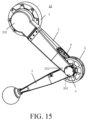
- FIG. 15 is a schematic diagram of a wheel-footed bimodal mechanical leg 14 according to an exemplary embodiment of this application.
- the wheel-footed bimodal mechanical leg includes a driving apparatus 1, a thigh unit 2, and a calf unit 3.
- a root end 201 of the thigh unit 2 is connected to the driving apparatus 1.
- a joint end 202 of the thigh unit 2 is hingedly connected to a joint end 301 of the calf unit 3 by a rotary shaft 4.
- the rotary shaft 4 is transmission-connected to a traveling wheel 5.
- a pin hole is formed on the rotary shaft 4.
- the driving apparatus 1 is connected to the traveling wheel 5 by a transmission apparatus 6.
- a traveling wheel 5 is fixed on at least one position of two ends or a middle position of the rotary shaft 4. There may be one or more traveling wheels 5.
- the calf unit 3 includes a locking component.
- the locking component (not shown in FIG. 14 , refer to FIG. 15 ) is provided inside the calf unit 3.
- a first mode in which the locking component is inserted into the pin hole on the rotary shaft 4, the calf unit 3 and the rotary shaft 4 are locked to each other.
- the calf unit 3 is fixedly connected to the rotary shaft 4, so that the calf driving apparatus 153 drives the calf unit 3 through the rotary shaft 4 to travel in the footed movement mode.
- a second mode in which the locking component is pulled out from the pin hole on the rotary shaft 4, the calf unit 3 and the rotary shaft 4 are unlocked from each other.
- the calf unit 3 is rotatably connected to the rotary shaft 4, so that the calf driving apparatus 153 drives the traveling wheel 5 through the rotary shaft 4 to travel in the wheeled movement mode without driving the calf unit 3 to move.
- Working principles of the foregoing wheel-footed bimodal mechanical leg 14 include: In the first mode in which the locking component is inserted into the pin hole on the rotary shaft 4, the calf unit 3 is fixedly connected to the rotary shaft 4. When the driving apparatus 1 drives the traveling wheel 5 through the rotary shaft 4 to rotate forward, the calf unit 3 is also driven to rotate forward. When the driving apparatus 1 drives the traveling wheel 5 through the rotary shaft 4 to rotate backward, the calf unit 3 is also driven to rotate backward.
- the footed movement can be implemented by repeatedly performing the foregoing process.
- the calf unit 3 is rotatably connected to the rotary shaft 4, that is, the rotary shaft 4 and the traveling wheel 5 may freely rotate relative to the calf unit 3.
- the driving apparatus 1 drives the traveling wheel 5 through the rotary shaft 4 to rotate forward, thereby implementing the wheeled movement.
- the locking component is arranged in the calf unit.
- the calf unit is fixedly connected to the rotary shaft, so that the driving apparatus drives the calf unit through the rotary shaft to travel in the footed mode.
- the calf unit is rotatably connected to the rotary shaft, so that the driving apparatus drives the traveling wheel through the rotary shaft to travel in the wheeled mode.
- only one driving apparatus is needed to implement the wheel-footed bimodal mechanical leg, which simplifies the structure of the wheel-footed bimodal mechanical leg, and is beneficial to the miniaturization and portability of the wheel-footed bimodal mechanical leg.
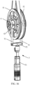
- FIG. 16 is a structural diagram of a locking component 7 according to an exemplary embodiment of this application.
- the locking component 7 is configured to perform locking or unlocking between the calf unit 3 and rotary shaft 4.
- the locking component 7 includes a linear motor 71 and a flat pin 72.
- the linear motor 71 is a transmission apparatus that converts electrical energy into mechanical energy for a linear movement.
- the calf unit 3 includes a motor fixing base therein.
- the motor fixing base fixes the linear motor 71 to an inner wall of the calf unit 3.
- the flat pin 72 is fixed to an output end of the linear motor 71.
- the calf unit 3 is fixedly connected to the rotary shaft 4.
- the calf unit 3 is rotatably connected to the rotary shaft 4.
- the calf unit 3 and the rotary shaft 4 are locked to each other, and the calf unit 3 is fixedly connected to the rotary shaft 4.
- the rotary shaft 4 drives the traveling wheel 5 to rotate, the calf unit 3 also rotates correspondingly.
- the calf unit 3 and the rotary shaft 4 are unlocked from each other, and the calf unit 3 is rotatably connected to the rotary shaft 4.
- the rotary shaft 4 drives the traveling wheel 5 to rotate, the calf unit 3 does not rotate correspondingly.
- At least two sets of the pin holes 4 are distributed on the rotary shaft along a radial direction.
- Each set of pin holes 43 includes two parallel pin holes 43.
- an angle between each set of pin holes 43 is 90 degrees.
- the flat pin 72 includes two parallel pin shafts 73.
- the pin shaft 73 corresponds to the pin hole. That is, a spacing (e.g., distance, separation etc.) between the two parallel pin shafts 73 is equal to a spacing between two parallel pin holes 43.
- An end shape of the pin shaft 73 matches the pin hole shape of the pin hole 43.
- At least two sets of pin holes 43 may be uniformly distributed or non-uniformly distributed along a radial direction of the rotary shaft.
- the traveling wheel 5 includes at least one traveling wheel.
- the locking component provided in this embodiment is locked by inserting the flat pin 72 into the pin hole 43 of the traveling wheel 5 under the driving of the linear motor 71, and is unlocked by pulling the flat pin 72 out from the pin hole 43 of the traveling wheel 5 under the driving of the linear motor 71.
- the linear motor 71 is hidden inside the calf unit 3, so that the structure is relatively simple, which can better ensure the miniaturization and portability of the calf unit 3.
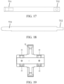
- FIG. 17 and FIG. 18 are respectively a front view and a top view of a pin shaft 73 according to an exemplary embodiment of this application.
- the pin shaft 73 includes an end 731 and a fixed end 732.
- An end shape of the end 731 is a first wedge shape for the end 731 to be inserted into the pin hole 43.
- a fixed hole is formed on the fixed end 732.
- the fixed end 732 is configured to be fixed on a base of the flat pin 72 of the linear motor 71.
- the base of the flat pin 72 may include 2 parallel fixed beams. The two fixed beams clamp the fixed ends 732 of the two pin shafts 73 on the upper and lower sides, and are fixed with a rivet or a screw. Middle portions of the two fixed beams are fixed to an output end of the linear motor 71.
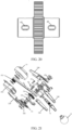
- FIG. 19 and FIG. 20 are respectively a cross-sectional view and a front view of a rotary shaft 4 according to an exemplary embodiment of this application.
- a driving wheel 34 is fixed to or formed in a middle portion of the rotary shaft 4.
- Four sets of pin holes 43 are formed on shaft bodies located on both sides of the driving wheel 34.
- Each set of pin holes 43 includes two pin holes 43.
- the pin holes 43 are in a shape of a second wedge shape. The first wedge shape and the second wedge shape match each other.
- the pin hole shape of the pin hole 43 matches the end shape of the pin shaft 73. That is, the pin hole shape of the pin hole 43 snugly fits the end shape of the pin shaft 73.
- the pin shaft 73 and the pin hole 43 that are provided in this embodiment and that are of wedge-shaped structures (15 and 16) that match each other can ensure that the pin shaft and the rotary shaft implement snug fitting without a gap. In this way, the robot dog does not loosen or has a gap during the wheeled or footed movement.
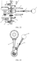
- FIG. 21 and FIG. 22 are respectively exploded views of a wheel-footed bimodal mechanical leg 14 according to another exemplary embodiment of this application from two viewing angles.
- the wheel-footed bimodal mechanical leg includes: a driving apparatus 1, a thigh unit 2, a calf unit 3, a rotary shaft 4, a traveling wheel 5, a transmission apparatus 6, a locking component 7, and a sole portion 8.
- the driving apparatus 1 includes a rotary motor 11 and a transmission wheel 533.
- the rotary motor 11 is fixedly connected to the transmission wheel 533.
- the rotary motor 11 is configured to provide a rotational driving force.
- the transmission wheel 533 is connected to the transmission apparatus 6.
- the transmission apparatus 6 is a belt or a chain.
- the belt is used as an example for description in this embodiment.
- the thigh unit 2 includes a first thigh portion 220 and a second thigh portion 240 that are detachably connected to each other.
- the first thigh portion 220 and the second thigh portion 240 are in a plugged connection, or are connected by using a screw or a nut.
- the first thigh portion 220 and the second thigh portion 240 enclose a casing portion of the thigh unit 2, and form an inner accommodation cavity of the thigh unit 2.
- the first thigh portion 220 is located on a first side of the transmission apparatus 6.
- the second thigh portion 240 is located on a second side of the transmission apparatus 6.
- the thigh unit 2 further includes a belt pressing apparatus 23 inside.
- the belt pressing apparatus 23 is in pressing contact with an outer surface of the belt.
- the calf unit 3 includes a first calf portion 320 and a second calf portion 340 that are detachably connected to each other.
- the first calf portion 320 and the second calf portion 340 are in plugged connection, or are connected by using a screw or a nut.
- the first calf portion 320 and the second calf portion 340 enclose a casing portion of the calf unit 3, and form an inner accommodation cavity of the calf unit 3.
- the first calf portion 320 is located on a first side of the transmission apparatus 6.
- the second calf portion 340 is located on a second side of the transmission apparatus 6.
- An other end of the calf unit 3 is connected to a sole portion 8.
- the material of the sole portion 8 may be a wear-resistant material such as rubber or wood.
- At least one of the first thigh portion 220, the second thigh portion 240, the first calf portion 320, or the second calf portion 340 is formed by splicing two plate-like structures belonging to a same side.
- the two plate-like structures are in a riveted, snap-fit plugged, or screwed connection.
- the first thigh portion 220 in the figure includes the two plate-like structures, to facilitate maintenance and replacement.
- the first thigh portion 220, the second thigh portion 240, the first calf portion 320, and the second calf portion 340 are sleeved on the rotary shaft 4 through bearings.
- a first shaft sleeve 41 is further sleeved between the first thigh portion 220 and the first calf portion 320.
- the shaft sleeve 41 is configured to separate a bearing inner ring of the bearing corresponding to the first thigh portion 220 from a bearing inner ring of the bearing corresponding to the first calf portion 320, to avoid direct friction between the two.
- a second shaft sleeve 42 is further sleeved between the second thigh portion 240 and the second calf portion 340.
- the second shaft sleeve 42 is configured to separate a bearing inner ring of the bearing corresponding to the second thigh portion 240 from a bearing inner ring of the bearing corresponding to the second calf portion 340, to avoid direct friction between the two.
- the first shaft sleeve 41 and the shaft sleeve 42 further play an axial positioning role.
- the joint end 301 of the calf unit 3 is clamped between the first thigh portion 220 and the second thigh portion 240.
- the rotary shaft 4 is clamped between the first calf portion 320 and the second calf portion 340.
- the traveling wheel 5 is clamped between the first calf portion 320 and the second 340.
- a driving wheel 34 is fixed to or formed in a middle portion of the rotary shaft 4.
- the driving wheel 34 is connected to the calf driving apparatus 153 by the transmission apparatus 6.
- the transmission apparatus 6 is a belt
- the driving wheel 34 is connected to the transmission wheel 533 by the belt.
- Four sets of pin holes 43 are formed on shaft bodies located on both sides of the driving wheel 34. Each set of pin holes 43 includes two pin holes 43.
- the traveling wheel 5 includes a first traveling wheel 51 and a second traveling wheel 52.
- the first traveling wheel 51 and the second traveling wheel 52 and the driving wheel 34 are fixedly connected.
- the traveling wheel 5 may alternatively be disposed an outer side of a joint of the joint end 301 relative to the robot 10, or disposed an inner side of the joint of the joint end 301 relative to the robot 10.
- the traveling wheel 5 in addition to the first traveling wheel 51 and the second traveling wheel 52, further includes a third traveling wheel 53 located on the outer side of the joint.
- a wheel diameter of a third traveling wheel 53 is the same as or different from that of the first traveling wheel 51 (and/or the second traveling wheel 52).
- the calf unit 3 further includes a locking component 7.
- the locking component 7 includes a linear motor 71 and a flat pin 72.
- the linear motor 71 is a transmission apparatus that converts electrical energy into mechanical energy for a linear movement.
- the calf unit 3 includes a motor fixing base 33 therein.
- the motor fixing base 33 fixes the linear motor 71 to an inner wall of the calf unit 3.
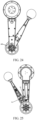
- an end of the sole portion 8 is in a plug connection with an end of the linear motor 71, and is clamped and fixed by the first calf portion 320 and the second calf portion 340, as shown in FIG. 23 .
- the flat pin 72 is fixed to an output end of the linear motor 71.
- a base of the flat pin 72 may include two parallel fixed beams.
- the two fixed beams clamp the fixed ends 732 of the two pin shafts 73 on the upper and lower sides, and are fixed with a rivet or a screw. Middle portions of the two fixed beams are fixed to an output end of the linear motor 71.
- a magnetic encoder 44 is further provided on the rotary shaft 4. As shown in FIG. 24 , the magnetic encoder 44 is configured to record a rotational position of the rotary shaft 4 in real time, so that a controller electrically connected to the magnetic encoder 44 can perform control to accurately insert the two pin shafts 73 into the pin hole 43.
- the pin hole shape of the pin hole 43 matches the end shape of the pin shaft 73. That is, the pin hole shape of the pin hole 43 snugly fits the end shape of the pin shaft 73.
- the locking component 7 is inserted into the pin hole on the rotary shaft.
- the calf unit 3 and the traveling wheel 5 are locked to each other, and the calf unit 3 is fixedly connected to the rotary shaft 4.
- the rotary shaft 4 drives the traveling wheel 5 to rotate, the calf unit 3 also rotates with the traveling wheel 5.
- the locking component 7 is pulled out from the pin hole on the rotary shaft.
- the calf unit 3 and the traveling wheel 5 are unlocked.
- the calf unit 3 is rotatably connected to the rotary shaft 4.
- the rotary shaft 4 drives the traveling wheel 5 to rotate, the calf unit 3 does not rotate with the traveling wheel 5.
- the thigh unit 2 and the rotary shaft 4 are always rotatably connected.
- the traveling wheel 5 can rotate forward or backward relative to the thigh unit 2.
- the calf unit 3 may include a first magnetic component 91 thereon, and the thigh unit 2 may include a second magnetic component 92 thereon.
- the first magnetic component 91 and the second magnetic component 92 may be attracted to each other.
- One of the first magnetic component 91 and the second magnetic component 92 is a magnet, and the other of the first magnetic component 91 and the second magnetic component 92 is a magnet or an iron block.
- the locking component is arranged in the calf unit, so that when the locking component is inserted into the pin hole of the rotary shaft, the calf unit and the rotary shaft are locked.
- the calf unit is fixedly connected to the rotary shaft, so that the driving apparatus drives the calf unit through the rotary shaft to travel in the footed mode.
- the calf unit is rotatably connected to the rotary shaft, so that the driving apparatus drives the traveling wheel through the rotary shaft to travel in the wheeled mode.
- only one driving apparatus is needed to implement the wheel-footed bimodal mechanical leg, which simplifies the structure of the wheel-footed bimodal mechanical leg, and is beneficial to the miniaturization and portability of the wheel-footed bimodal mechanical leg.
- the locking component provided in this embodiment locks by driving the flat pin to be inserted into the pin hole of the traveling wheel through the linear motor, and unlocks by driving the flat pin to be pulled out from the pin hole of the traveling wheel through the linear motor.
- the linear motor is hidden inside the calf unit, so that the structure is relatively simple, which can better ensure the miniaturization and portability of the calf unit.
- a belt pressing apparatus provided in this embodiment can ensure that the belt in the transmission apparatus is kept in a pressed state, thereby ensuring the driving force applied by the driving apparatus to the traveling wheel.
- the first magnetic component and the second magnetic component provided in this embodiment can fix the thigh unit and the calf unit when the wheel-footed bimodal mechanical leg is in the wheeled mode, so that the calf unit does not affect normal traveling of the traveling wheel.
- the program may be stored in a computer-readable storage medium.
- the storage medium may be: a ROM, a magnetic disk, or an optical disc.
Landscapes
- Engineering & Computer Science (AREA)
- Chemical & Material Sciences (AREA)
- Combustion & Propulsion (AREA)
- Transportation (AREA)
- Mechanical Engineering (AREA)
- Manipulator (AREA)
Claims (13)
- Jambe mécanique bimodale à pied avec roue (14), comprenant : un appareil d'entraînement (1), une unité cuisse (2), et une unité mollet (3),une extrémité articulation (202) de l'unité cuisse (2) est reliée de façon articulée à une extrémité articulation (301) de l'unité mollet (3) par un arbre rotatif (4), l'arbre rotatif (4) étant relié de façon fixe à une roue de déplacement (5) pour réaliser un mouvement en mode roue lorsque la roue de déplacement (5) touche le sol, et l'appareil d'entraînement (1) est relié à l'arbre rotatif (4) par un appareil de transmission (6) ;l'unité mollet (3) comprend un composant de verrouillage (7) ;l'unité mollet (3) est reliée de façon fixe à l'arbre rotatif lorsque le composant de verrouillage (7) est dans un état verrouillé ; etl'unité mollet (3) est reliée de façon rotative à l'arbre rotatif lorsque le composant de verrouillage (7) est dans un état déverrouillé ;caractérisée en ce que l'unité mollet (3) est reliée de façon fixe à l'arbre rotatif (4) par la roue de déplacement (5) lorsque le composant de verrouillage (7) est dans l'état verrouillé ; ou,un trou de broche (43) est formé sur l'arbre rotatif (4), l'unité mollet (3) est reliée de façon fixe à l'arbre rotatif (4) dans un état verrouillé dans lequel le composant de verrouillage (7) est inséré dans le trou de broche (43), et l'unité mollet (3) est reliée de façon rotative à l'arbre rotatif (4) dans un état déverrouillé dans lequel le composant de verrouillage (7) est extrait du trou de broche (43).
- Jambe mécanique bimodale à pied avec roue (14) selon la revendication 1, dans laquelle la roue de déplacement (5) comprend une rainure de broche (74) sur celle-ci, le composant de verrouillage (7) comprend un moteur linéaire (71) et une broche plate (72), et la broche plate (72) est fixée à une extrémité de sortie du moteur linéaire (71),le composant de verrouillage (7) est dans l'état verrouillé lorsque la broche plate (72) est insérée dans la rainure de broche (74) ; etle composant de verrouillage (7) est dans l'état déverrouillé lorsque la broche plate (72) quitte la rainure de broche (74).
- Jambe mécanique bimodale à pied avec roue (14) selon la revendication 2, dans laquelle au moins deux rainures de broche (74) sont radialement distribuées sur la roue de déplacement (5), dans laquelle, de préférence :les au moins deux rainures de broche (74) incluent une première rainure de broche et une seconde rainure de broche, la roue de déplacement (5) comprend une première roue de déplacement (51) et une seconde roue de déplacement (52) ; etla première rainure de broche est formée sur une première surface de roue de la première roue de déplacement (51) faisant face à la seconde roue de déplacement (52), et la seconde rainure de broche est formée sur une seconde surface de roue de la seconde roue de déplacement (52) faisant face à la première roue de déplacement (51), dans laquelle le nombre et les positions de rainurage des rainures de broche (74) sur la première surface de roue et la seconde surface de roue sont les mêmes.
- Jambe mécanique bimodale à pied avec roue (14) selon la revendication 1, dans laquelle le composant de verrouillage (7) comprend un moteur linéaire (71) et une broche plate (72), et la broche plate (72) est fixée à une extrémité de sortie du moteur linéaire (71) ;l'unité mollet (3) est reliée de façon fixe à l'arbre rotatif (4) dans l'état verrouillé dans lequel la broche plate (72) est insérée dans le trou de broche (43) ; etl'unité mollet (3) est reliée de façon rotative à l'arbre rotatif (4) dans l'état déverrouillé dans lequel la broche plate (72) est extraite du trou de broche (43).
- Jambe mécanique bimodale à pied avec roue (14) selon la revendication 4, dans laquelleau moins deux ensembles de trous de broche (43) sont distribués sur l'arbre rotatif (4) le long d'une direction radiale, chaque ensemble de trous de broche (43) comprenant deux trous de broche parallèles (43) ; etla broche plate (72) comprend deux tiges de broche parallèles (73), les tiges de broche (73) correspondant aux trous de broche ;dans laquelle une forme d'extrémité de la tige de broche (73) est une première forme de cale, une forme de trou de broche du trou de broche (43) est une seconde forme de cale, et la première forme de cale correspond à la seconde forme de cale.
- Jambe mécanique bimodale à pied avec roue (14) selon l'une quelconque des revendications 2 à 5, dans laquelle l'unité mollet (3) comprend une base de fixation de moteur (33) dans celle-ci, et la base de fixation de moteur (33) fixe le moteur linéaire (71) à une paroi intérieure de l'unité mollet (3).
- Jambe mécanique bimodale à pied avec roue (14) selon l'une quelconque des revendications 1 à 6, dans laquelle l'arbre rotatif (4) est en outre relié de façon fixe à une roue d'entraînement (34) ; etla roue d'entraînement (34) est reliée à l'appareil d'entraînement (1) par l'appareil de transmission (6),dans laquelle l'appareil de transmission (6) comprend une courroie ; l'unité cuisse (2) comprend un appareil de pression de courroie (23) ; etla roue d'entraînement est reliée à l'appareil d'entraînement (1) par la courroie, et l'appareil de pression de courroie (23) est en contact de pression avec une autre surface de la courroie.
- Jambe mécanique bimodale à pied avec roue (14) selon l'une quelconque des revendications 1 à 6, dans laquellel'unité mollet (3) comprend un premier composant magnétique (91) sur celle-ci, et l'unité cuisse (2) comprend un second composant magnétique (92) sur celle-ci ; et le premier composant magnétique (91) et le second composant magnétique (92) sont attirés l'un vers l'autre lorsque le composant de verrouillage (7) est dans l'état déverrouillé, et l'unité cuisse (2) et l'unité mollet (3) sont dans un état contracté et fermé ; etun du premier composant magnétique (91) et du second composant magnétique (92) est un aimant, et l'un du premier composant magnétique (91) et du second composant magnétique (92) est un aimant ou un bloc de fer.
- Jambe mécanique bimodale à pied avec roue (14) selon l'une quelconque des revendications 1 à 6, dans laquelle l'unité cuisse (2) comprend une première partie de cuisse (220) et une seconde partie de cuisse (240) qui sont reliées de façon détachable l'une à l'autre, et l'unité mollet (3) comprend une première partie de mollet (320) et une seconde unité mollet (340) qui sont reliées de façon détachable l'une à l'autre ; et
la première partie de cuisse (220) et la première partie de mollet (320) sont situées sur un premier côté de l'appareil de transmission (6), et la seconde partie de cuisse (240) et la seconde partie de mollet (340) sont situées sur un second côté de l'appareil de transmission (6). - Jambe mécanique bimodale à pied avec roue (14) selon la revendication 9, dans laquelle l'extrémité articulation (301) de l'unité mollet (3) est serrée entre la première partie de cuisse (220) et la seconde partie de cuisse (240), et l'arbre rotatif (4) est serré entre la première partie de mollet (320) et la seconde partie de mollet (340).
- Jambe mécanique bimodale à pied avec roue (14) selon la revendication 9, dans laquelle la roue de déplacement (5) est serrée entre la première partie de mollet (320) et la seconde partie de mollet (340).
- Jambe mécanique bimodale à pied avec roue (14) selon la revendication 6, dans laquelle un premier manchon d'arbre (41) et un second manchon d'arbre (42) sont en outre montés sur l'arbre rotatif (4) ;le premier manchon d'arbre (41) est monté entre la première partie de cuisse (220) et la première partie de mollet (320) ; etle second manchon d'arbre (42) est monté entre la seconde partie de cuisse (240) et la seconde partie de mollet (340).
- Robot, comprenant :
la jambe mécanique bimodale à pied avec roue (14) selon l'une quelconque des revendications 1 à 12.
Applications Claiming Priority (4)
| Application Number | Priority Date | Filing Date | Title |
|---|---|---|---|
| CN202010663751.7A CN113911228B (zh) | 2020-07-10 | 2020-07-10 | 轮足双模态机械腿以及机器人 |
| CN202010662698.9A CN111731405B (zh) | 2020-07-10 | 2020-07-10 | 机器人 |
| CN202010769371.1A CN111891251B (zh) | 2020-08-03 | 2020-08-03 | 机械腿以及机器狗 |
| PCT/CN2021/093698 WO2022007499A1 (fr) | 2020-07-10 | 2021-05-13 | Jambe mécanique à double mode de jambe de roue et robot |
Publications (4)
| Publication Number | Publication Date |
|---|---|
| EP4039567A1 EP4039567A1 (fr) | 2022-08-10 |
| EP4039567A4 EP4039567A4 (fr) | 2023-11-01 |
| EP4039567B1 true EP4039567B1 (fr) | 2025-02-12 |
| EP4039567C0 EP4039567C0 (fr) | 2025-02-12 |
Family
ID=79553683
Family Applications (1)
| Application Number | Title | Priority Date | Filing Date |
|---|---|---|---|
| EP21838701.7A Active EP4039567B1 (fr) | 2020-07-10 | 2021-05-13 | Jambe mécanique à double mode de jambe de roue et robot |
Country Status (4)
| Country | Link |
|---|---|
| US (1) | US12485979B2 (fr) |
| EP (1) | EP4039567B1 (fr) |
| JP (1) | JP7542637B2 (fr) |
| WO (1) | WO2022007499A1 (fr) |
Families Citing this family (23)
| Publication number | Priority date | Publication date | Assignee | Title |
|---|---|---|---|---|
| CN114275072B (zh) * | 2022-01-19 | 2023-04-07 | 西湖机器人科技(杭州)有限公司 | 一种可以实现机器人轮足两种状态切换的装置 |
| CN114435022B (zh) * | 2022-01-28 | 2024-08-13 | 德清县浙工大莫干山研究院 | 一种轮足复合式轮子 |
| JP7715654B2 (ja) * | 2022-02-16 | 2025-07-30 | 鹿島建設株式会社 | 比抵抗測定装置及び比抵抗測定方法 |
| CN114852207A (zh) * | 2022-04-26 | 2022-08-05 | 中国北方车辆研究所 | 一种轴传动的三自由度轮足行走机构 |
| KR102645781B1 (ko) * | 2022-06-17 | 2024-03-08 | 양수상 | 보행모드와 주행모드의 전환이 가능한 이동 로봇 |
| CN114953876B (zh) * | 2022-07-01 | 2025-04-08 | 北京理工大学 | 一种用于轮腿式车辆的减振机构及其轮腿式结构 |
| CN116985930A (zh) * | 2022-07-25 | 2023-11-03 | 腾讯科技(深圳)有限公司 | 机器人的控制方法、装置、机器人、存储介质及程序产品 |
| CN116991090B (zh) * | 2022-07-25 | 2025-07-15 | 腾讯科技(深圳)有限公司 | 机器人的运动起摆方法、装置、机器人、存储介质及产品 |
| JP1762281S (ja) * | 2022-10-19 | 2024-01-25 | ロボット | |
| CN116001943A (zh) * | 2022-12-14 | 2023-04-25 | 东莞市本末科技有限公司 | 机械腿及机器人 |
| CA223389S (en) * | 2023-03-06 | 2024-10-30 | Hangzhou Yushu Tech Co Ltd | Quadruped robot |
| CN116279891B (zh) * | 2023-03-20 | 2024-09-27 | 大连理工大学 | 一种轮足复合机器人及其控制方法 |
| CN116238615A (zh) * | 2023-04-12 | 2023-06-09 | 吉林大学 | 一种小型可折叠轮腿式移动机器人 |
| US20240351710A1 (en) * | 2023-04-19 | 2024-10-24 | Hyundai Motor Company | Hybrid vehicle for use in lunar exploration |
| USD1055129S1 (en) * | 2023-04-28 | 2024-12-24 | Hengzhi Future (Chongqing) Innovation Technology Co., Ltd. | Robot dog |
| CN116902106B (zh) * | 2023-07-13 | 2025-11-28 | 浙江海洋大学 | 一种用于仿生机器人的伸缩型移动结构 |
| CN116985932B (zh) * | 2023-08-23 | 2026-04-17 | 昆明理工大学 | 一种行星齿轮差速原理的轮足复合机器人腿部结构、轮足复合机器人 |
| CN117508401A (zh) * | 2023-12-23 | 2024-02-06 | 深圳逐际动力科技有限公司 | 双足机器人的腿结构、人形机器人、机器人 |
| CN117444934B (zh) * | 2023-12-25 | 2024-03-26 | 国仪大为(北京)智能科技有限公司 | 一种康养陪护变形机器人 |
| KR20250132780A (ko) * | 2024-02-29 | 2025-09-05 | 삼성전자주식회사 | 이동 로봇 |
| CN120663293A (zh) * | 2024-03-18 | 2025-09-19 | 北京有竹居网络技术有限公司 | 机器人运动控制方法、装置、机器人和存储介质 |
| CN119389324B (zh) * | 2024-11-04 | 2025-11-18 | 洛阳润禾测控技术有限公司 | 一种具有切换行走方式的机器狗 |
| CN121180325A (zh) * | 2025-11-26 | 2025-12-23 | 复旦大学 | 一种轮足复合式多模态机器人及其工作方法 |
Family Cites Families (35)
| Publication number | Priority date | Publication date | Assignee | Title |
|---|---|---|---|---|
| JPS6243370A (ja) * | 1985-08-22 | 1987-02-25 | Mitsubishi Heavy Ind Ltd | 脚車輪形移動ロボツトの制御方法 |
| US6481512B1 (en) | 1999-01-28 | 2002-11-19 | Sony Corporation | Joint device for robot device and leg- walking robot device |
| JP2004230499A (ja) * | 2003-01-29 | 2004-08-19 | Tostem Corp | 自走撮影ロボット及び家屋の床下撮影診断システム |
| JP4258456B2 (ja) * | 2004-09-14 | 2009-04-30 | トヨタ自動車株式会社 | ロボット |
| CN101219683B (zh) * | 2008-01-25 | 2010-09-08 | 清华大学 | 轮足两用式移动机器人 |
| CN101224764B (zh) | 2008-02-01 | 2010-09-08 | 清华大学 | 仿生轮足两用式机器人 |
| CN101298260B (zh) | 2008-06-11 | 2010-06-02 | 清华大学 | 低功耗双足步行移动系统及其步行控制方法 |
| US9233017B2 (en) * | 2009-09-28 | 2016-01-12 | Tokyo University Of Science Foundation | Lower back assistance apparatus |
| CN201626257U (zh) | 2010-02-25 | 2010-11-10 | 好孩子儿童用品有限公司 | 童车车轮的定向机构及童车 |
| CN103001151B (zh) | 2012-12-05 | 2015-12-02 | 国网山东省电力公司电力科学研究院 | 具有越障功能的线路机器人驱动臂 |
| JP6069146B2 (ja) * | 2013-09-12 | 2017-02-01 | 本田技研工業株式会社 | 脚式移動ロボットの脚体構造 |
| CN104029745B (zh) | 2014-05-21 | 2016-01-06 | 浙江大学 | 一种腿轮混合式液压机械腿 |
| CN104443104B (zh) | 2014-12-10 | 2017-01-25 | 山东大学 | 轮足式机器人腿结构及具有该腿结构的轮足式机器人 |
| CN104608837B (zh) * | 2015-01-16 | 2017-04-26 | 燕山大学 | 轮腿混合式四足机器人 |
| KR101731731B1 (ko) | 2015-12-03 | 2017-04-28 | 서강대학교산학협력단 | 다족 주행로봇 |
| CN105711675B (zh) * | 2016-01-25 | 2017-10-20 | 东南大学 | 一种应用于轮腿复合式机器人的轮腿机构及控制方法 |
| CN105946483B (zh) | 2016-05-06 | 2018-01-30 | 重庆大学 | 具有变胞式机械腿的两栖多足机器人 |
| CN106428284B (zh) | 2016-08-30 | 2018-11-02 | 陆任行 | 多足独立移动运载装置 |
| CN107856753B (zh) * | 2017-11-28 | 2023-06-06 | 华中科技大学 | 一种基于多传感器融合的隧道渗水检测机器人 |
| CN107933728A (zh) | 2017-12-22 | 2018-04-20 | 华南理工大学广州学院 | 清洁爬壁机器人的腿部结构 |
| CN108340985A (zh) | 2018-04-07 | 2018-07-31 | 吉林大学 | 一种多适应性轮足切换移动平台 |
| CN110304167A (zh) * | 2019-07-16 | 2019-10-08 | 深圳市爱因派科技有限公司 | 轮腿复合结构及轮腿复合四足仿生机器人 |
| CN110549341A (zh) | 2019-09-24 | 2019-12-10 | 山东省智能机器人应用技术研究院 | 工业机器人坐标定位系统和方法 |
| CN110962955B (zh) | 2019-11-19 | 2020-11-20 | 北京空间飞行器总体设计部 | 一种用于星球探测的少驱动轮腿式复合机器人 |
| CN111301550B (zh) * | 2019-11-28 | 2021-07-13 | 江汉大学 | 一种移动机器人轮足结构及其控制方法 |
| CN111204382A (zh) * | 2020-03-17 | 2020-05-29 | 杭州云深处科技有限公司 | 一种轮腿结合的四足机器人 |
| CN111391937A (zh) | 2020-04-13 | 2020-07-10 | 高路平 | 一种具有柔性脊柱的四足仿生机器人 |
| CN111591363B (zh) * | 2020-05-27 | 2021-04-27 | 中国人民解放军国防科技大学 | 一种高集成轮腿复合机构及运载平台 |
| CN111891251B (zh) * | 2020-08-03 | 2023-11-03 | 腾讯科技(深圳)有限公司 | 机械腿以及机器狗 |
| CN111731405B (zh) * | 2020-07-10 | 2023-12-01 | 腾讯科技(深圳)有限公司 | 机器人 |
| EP4331777A4 (fr) * | 2021-04-26 | 2025-03-05 | Lifehub Inc. | Dispositif mobile |
| CN115447690B (zh) * | 2021-06-09 | 2025-01-21 | 腾讯科技(深圳)有限公司 | 一种机械腿和机器人 |
| CN113602378A (zh) * | 2021-07-28 | 2021-11-05 | 南方科技大学 | 一种仿生四足机器人 |
| CN116118892B (zh) * | 2021-11-12 | 2024-10-01 | 腾讯科技(深圳)有限公司 | 轮足双模态机械腿和机器人 |
| KR102854802B1 (ko) * | 2023-07-05 | 2025-09-04 | 국민대학교산학협력단 | 다족 보행 로봇의 보행 시스템 및 보행 제어 방법 |
-
2021
- 2021-05-13 JP JP2022552628A patent/JP7542637B2/ja active Active
- 2021-05-13 WO PCT/CN2021/093698 patent/WO2022007499A1/fr not_active Ceased
- 2021-05-13 EP EP21838701.7A patent/EP4039567B1/fr active Active
-
2022
- 2022-05-18 US US17/747,915 patent/US12485979B2/en active Active
Also Published As
| Publication number | Publication date |
|---|---|
| JP7542637B2 (ja) | 2024-08-30 |
| JP2023517001A (ja) | 2023-04-21 |
| EP4039567C0 (fr) | 2025-02-12 |
| US12485979B2 (en) | 2025-12-02 |
| US20220274657A1 (en) | 2022-09-01 |
| EP4039567A4 (fr) | 2023-11-01 |
| WO2022007499A1 (fr) | 2022-01-13 |
| EP4039567A1 (fr) | 2022-08-10 |
Similar Documents
| Publication | Publication Date | Title |
|---|---|---|
| EP4039567B1 (fr) | Jambe mécanique à double mode de jambe de roue et robot | |
| CN111731405B (zh) | 机器人 | |
| CN111891251B (zh) | 机械腿以及机器狗 | |
| CN110217311B (zh) | 一种基于同轴并联机构的敏捷四足机器人 | |
| Tu et al. | FreeSN: A freeform strut-node structured modular self-reconfigurable robot-design and implementation | |
| US9097325B2 (en) | Motorized drive system and method for articulating a joint | |
| US6323615B1 (en) | Modular articulated robot structure | |
| US6686717B2 (en) | Modular articulated structure | |
| US20020166404A1 (en) | Robotic manipulator | |
| CN113911228B (zh) | 轮足双模态机械腿以及机器人 | |
| CN206811948U (zh) | 机器人下肢 | |
| CN110406613B (zh) | 一种多自由度轻型单腿机构 | |
| CN112223340B (zh) | 适用于自重构机器人的多爪抓取机构 | |
| Kalouche | Design for 3d agility and virtual compliance using proprioceptive force control in dynamic legged robots | |
| WO2018209763A1 (fr) | Membre inférieur robotique | |
| CN112849295A (zh) | 一种多相位三维凸轮式仿生足式机器人 | |
| US20050039556A1 (en) | Rotational apparatus | |
| WO2004051188A2 (fr) | Systeme de propulsion induite par couple | |
| HK40029474A (en) | Robot | |
| HK40029474B (zh) | 机器人 | |
| CN115520301B (zh) | 一种可分离的仿生蜈蚣机器人及其接合分离方法 | |
| Ren et al. | Xiaotian-hybrid: a novel wheeled-quadruped platform | |
| CN113291387B (zh) | 一种具有躯干关节的四足机器人 | |
| CN214724346U (zh) | 一种机器人的肩关节以及机器人 | |
| CN113635989A (zh) | 一种集成式多足机器人 |
Legal Events
| Date | Code | Title | Description |
|---|---|---|---|
| STAA | Information on the status of an ep patent application or granted ep patent |
Free format text: STATUS: THE INTERNATIONAL PUBLICATION HAS BEEN MADE |
|
| PUAI | Public reference made under article 153(3) epc to a published international application that has entered the european phase |
Free format text: ORIGINAL CODE: 0009012 |
|
| STAA | Information on the status of an ep patent application or granted ep patent |
Free format text: STATUS: REQUEST FOR EXAMINATION WAS MADE |
|
| 17P | Request for examination filed |
Effective date: 20220503 |
|
| AK | Designated contracting states |
Kind code of ref document: A1 Designated state(s): AL AT BE BG CH CY CZ DE DK EE ES FI FR GB GR HR HU IE IS IT LI LT LU LV MC MK MT NL NO PL PT RO RS SE SI SK SM TR |
|
| DAV | Request for validation of the european patent (deleted) | ||
| DAX | Request for extension of the european patent (deleted) | ||
| A4 | Supplementary search report drawn up and despatched |
Effective date: 20231002 |
|
| RIC1 | Information provided on ipc code assigned before grant |
Ipc: B62D 57/032 20060101ALI20230926BHEP Ipc: B62D 57/028 20060101AFI20230926BHEP |
|
| STAA | Information on the status of an ep patent application or granted ep patent |
Free format text: STATUS: EXAMINATION IS IN PROGRESS |
|
| 17Q | First examination report despatched |
Effective date: 20240621 |
|
| 17Q | First examination report despatched |
Effective date: 20240626 |
|
| GRAP | Despatch of communication of intention to grant a patent |
Free format text: ORIGINAL CODE: EPIDOSNIGR1 |
|
| STAA | Information on the status of an ep patent application or granted ep patent |
Free format text: STATUS: GRANT OF PATENT IS INTENDED |
|
| INTG | Intention to grant announced |
Effective date: 20241106 |
|
| GRAS | Grant fee paid |
Free format text: ORIGINAL CODE: EPIDOSNIGR3 |
|
| GRAA | (expected) grant |
Free format text: ORIGINAL CODE: 0009210 |
|
| STAA | Information on the status of an ep patent application or granted ep patent |
Free format text: STATUS: THE PATENT HAS BEEN GRANTED |
|
| AK | Designated contracting states |
Kind code of ref document: B1 Designated state(s): AL AT BE BG CH CY CZ DE DK EE ES FI FR GB GR HR HU IE IS IT LI LT LU LV MC MK MT NL NO PL PT RO RS SE SI SK SM TR |
|
| REG | Reference to a national code |
Ref country code: GB Ref legal event code: FG4D |
|
| REG | Reference to a national code |
Ref country code: CH Ref legal event code: EP |
|
| REG | Reference to a national code |
Ref country code: DE Ref legal event code: R096 Ref document number: 602021026132 Country of ref document: DE |
|
| REG | Reference to a national code |
Ref country code: IE Ref legal event code: FG4D |
|
| U01 | Request for unitary effect filed |
Effective date: 20250228 |
|
| U07 | Unitary effect registered |
Designated state(s): AT BE BG DE DK EE FI FR IT LT LU LV MT NL PT RO SE SI Effective date: 20250310 |
|
| U20 | Renewal fee for the european patent with unitary effect paid |
Year of fee payment: 5 Effective date: 20250520 |
|
| PG25 | Lapsed in a contracting state [announced via postgrant information from national office to epo] |
Ref country code: RS Free format text: LAPSE BECAUSE OF FAILURE TO SUBMIT A TRANSLATION OF THE DESCRIPTION OR TO PAY THE FEE WITHIN THE PRESCRIBED TIME-LIMIT Effective date: 20250512 |
|
| PG25 | Lapsed in a contracting state [announced via postgrant information from national office to epo] |
Ref country code: PL Free format text: LAPSE BECAUSE OF FAILURE TO SUBMIT A TRANSLATION OF THE DESCRIPTION OR TO PAY THE FEE WITHIN THE PRESCRIBED TIME-LIMIT Effective date: 20250212 |
|
| PG25 | Lapsed in a contracting state [announced via postgrant information from national office to epo] |
Ref country code: ES Free format text: LAPSE BECAUSE OF FAILURE TO SUBMIT A TRANSLATION OF THE DESCRIPTION OR TO PAY THE FEE WITHIN THE PRESCRIBED TIME-LIMIT Effective date: 20250212 |
|
| PG25 | Lapsed in a contracting state [announced via postgrant information from national office to epo] |
Ref country code: NO Free format text: LAPSE BECAUSE OF FAILURE TO SUBMIT A TRANSLATION OF THE DESCRIPTION OR TO PAY THE FEE WITHIN THE PRESCRIBED TIME-LIMIT Effective date: 20250512 Ref country code: IS Free format text: LAPSE BECAUSE OF FAILURE TO SUBMIT A TRANSLATION OF THE DESCRIPTION OR TO PAY THE FEE WITHIN THE PRESCRIBED TIME-LIMIT Effective date: 20250612 |
|
| PG25 | Lapsed in a contracting state [announced via postgrant information from national office to epo] |
Ref country code: HR Free format text: LAPSE BECAUSE OF FAILURE TO SUBMIT A TRANSLATION OF THE DESCRIPTION OR TO PAY THE FEE WITHIN THE PRESCRIBED TIME-LIMIT Effective date: 20250212 |
|
| PG25 | Lapsed in a contracting state [announced via postgrant information from national office to epo] |
Ref country code: GR Free format text: LAPSE BECAUSE OF FAILURE TO SUBMIT A TRANSLATION OF THE DESCRIPTION OR TO PAY THE FEE WITHIN THE PRESCRIBED TIME-LIMIT Effective date: 20250513 |
|
| PG25 | Lapsed in a contracting state [announced via postgrant information from national office to epo] |
Ref country code: SM Free format text: LAPSE BECAUSE OF FAILURE TO SUBMIT A TRANSLATION OF THE DESCRIPTION OR TO PAY THE FEE WITHIN THE PRESCRIBED TIME-LIMIT Effective date: 20250212 |
|
| PG25 | Lapsed in a contracting state [announced via postgrant information from national office to epo] |
Ref country code: CZ Free format text: LAPSE BECAUSE OF FAILURE TO SUBMIT A TRANSLATION OF THE DESCRIPTION OR TO PAY THE FEE WITHIN THE PRESCRIBED TIME-LIMIT Effective date: 20250212 |
|
| PG25 | Lapsed in a contracting state [announced via postgrant information from national office to epo] |
Ref country code: SK Free format text: LAPSE BECAUSE OF FAILURE TO SUBMIT A TRANSLATION OF THE DESCRIPTION OR TO PAY THE FEE WITHIN THE PRESCRIBED TIME-LIMIT Effective date: 20250212 |
|
| PLBE | No opposition filed within time limit |
Free format text: ORIGINAL CODE: 0009261 |
|
| STAA | Information on the status of an ep patent application or granted ep patent |
Free format text: STATUS: NO OPPOSITION FILED WITHIN TIME LIMIT |
|
| REG | Reference to a national code |
Ref country code: CH Ref legal event code: H13 Free format text: ST27 STATUS EVENT CODE: U-0-0-H10-H13 (AS PROVIDED BY THE NATIONAL OFFICE) Effective date: 20251223 |
|
| REG | Reference to a national code |
Ref country code: CH Ref legal event code: L10 Free format text: ST27 STATUS EVENT CODE: U-0-0-L10-L00 (AS PROVIDED BY THE NATIONAL OFFICE) Effective date: 20251224 |
|
| PG25 | Lapsed in a contracting state [announced via postgrant information from national office to epo] |
Ref country code: CH Free format text: LAPSE BECAUSE OF NON-PAYMENT OF DUE FEES Effective date: 20250531 |
|
| 26N | No opposition filed |
Effective date: 20251113 |
|
| PG25 | Lapsed in a contracting state [announced via postgrant information from national office to epo] |
Ref country code: MC Free format text: LAPSE BECAUSE OF FAILURE TO SUBMIT A TRANSLATION OF THE DESCRIPTION OR TO PAY THE FEE WITHIN THE PRESCRIBED TIME-LIMIT Effective date: 20250212 |
|
| PGFP | Annual fee paid to national office [announced via postgrant information from national office to epo] |
Ref country code: GB Payment date: 20260324 Year of fee payment: 6 |
|
| PG25 | Lapsed in a contracting state [announced via postgrant information from national office to epo] |
Ref country code: IE Free format text: LAPSE BECAUSE OF NON-PAYMENT OF DUE FEES Effective date: 20250513 |