EP4039952A1 - Module de traitement des gaz d'échappement pour un syst?me d'échappement des gaz d'un moteur à combustion interne - Google Patents
Module de traitement des gaz d'échappement pour un syst?me d'échappement des gaz d'un moteur à combustion interne Download PDFInfo
- Publication number
- EP4039952A1 EP4039952A1 EP22150107.5A EP22150107A EP4039952A1 EP 4039952 A1 EP4039952 A1 EP 4039952A1 EP 22150107 A EP22150107 A EP 22150107A EP 4039952 A1 EP4039952 A1 EP 4039952A1
- Authority
- EP
- European Patent Office
- Prior art keywords
- exhaust gas
- housing
- gas treatment
- treatment unit
- locking
- Prior art date
- Legal status (The legal status is an assumption and is not a legal conclusion. Google has not performed a legal analysis and makes no representation as to the accuracy of the status listed.)
- Pending
Links
Images



Classifications
-
- F—MECHANICAL ENGINEERING; LIGHTING; HEATING; WEAPONS; BLASTING
- F01—MACHINES OR ENGINES IN GENERAL; ENGINE PLANTS IN GENERAL; STEAM ENGINES
- F01N—GAS-FLOW SILENCERS OR EXHAUST APPARATUS FOR MACHINES OR ENGINES IN GENERAL; GAS-FLOW SILENCERS OR EXHAUST APPARATUS FOR INTERNAL-COMBUSTION ENGINES
- F01N13/00—Exhaust or silencing apparatus characterised by constructional features
- F01N13/18—Construction facilitating manufacture, assembly, or disassembly
- F01N13/1838—Construction facilitating manufacture, assembly, or disassembly characterised by the type of connection between parts of exhaust or silencing apparatus, e.g. between housing and tubes, between tubes and baffles
- F01N13/1844—Mechanical joints
-
- F—MECHANICAL ENGINEERING; LIGHTING; HEATING; WEAPONS; BLASTING
- F01—MACHINES OR ENGINES IN GENERAL; ENGINE PLANTS IN GENERAL; STEAM ENGINES
- F01N—GAS-FLOW SILENCERS OR EXHAUST APPARATUS FOR MACHINES OR ENGINES IN GENERAL; GAS-FLOW SILENCERS OR EXHAUST APPARATUS FOR INTERNAL-COMBUSTION ENGINES
- F01N13/00—Exhaust or silencing apparatus characterised by constructional features
- F01N13/18—Construction facilitating manufacture, assembly, or disassembly
- F01N13/1888—Construction facilitating manufacture, assembly, or disassembly the housing of the assembly consisting of two or more parts, e.g. two half-shells
-
- F—MECHANICAL ENGINEERING; LIGHTING; HEATING; WEAPONS; BLASTING
- F01—MACHINES OR ENGINES IN GENERAL; ENGINE PLANTS IN GENERAL; STEAM ENGINES
- F01N—GAS-FLOW SILENCERS OR EXHAUST APPARATUS FOR MACHINES OR ENGINES IN GENERAL; GAS-FLOW SILENCERS OR EXHAUST APPARATUS FOR INTERNAL-COMBUSTION ENGINES
- F01N13/00—Exhaust or silencing apparatus characterised by constructional features
- F01N13/009—Exhaust or silencing apparatus characterised by constructional features having two or more separate purifying devices arranged in series
- F01N13/0097—Exhaust or silencing apparatus characterised by constructional features having two or more separate purifying devices arranged in series the purifying devices are arranged in a single housing
-
- F—MECHANICAL ENGINEERING; LIGHTING; HEATING; WEAPONS; BLASTING
- F01—MACHINES OR ENGINES IN GENERAL; ENGINE PLANTS IN GENERAL; STEAM ENGINES
- F01N—GAS-FLOW SILENCERS OR EXHAUST APPARATUS FOR MACHINES OR ENGINES IN GENERAL; GAS-FLOW SILENCERS OR EXHAUST APPARATUS FOR INTERNAL-COMBUSTION ENGINES
- F01N13/00—Exhaust or silencing apparatus characterised by constructional features
- F01N13/18—Construction facilitating manufacture, assembly, or disassembly
- F01N13/1805—Fixing exhaust manifolds, exhaust pipes or pipe sections to each other, to engine or to vehicle body
- F01N13/1811—Fixing exhaust manifolds, exhaust pipes or pipe sections to each other, to engine or to vehicle body with means permitting relative movement, e.g. compensation of thermal expansion or vibration
-
- F—MECHANICAL ENGINEERING; LIGHTING; HEATING; WEAPONS; BLASTING
- F01—MACHINES OR ENGINES IN GENERAL; ENGINE PLANTS IN GENERAL; STEAM ENGINES
- F01N—GAS-FLOW SILENCERS OR EXHAUST APPARATUS FOR MACHINES OR ENGINES IN GENERAL; GAS-FLOW SILENCERS OR EXHAUST APPARATUS FOR INTERNAL-COMBUSTION ENGINES
- F01N13/00—Exhaust or silencing apparatus characterised by constructional features
- F01N13/18—Construction facilitating manufacture, assembly, or disassembly
- F01N13/1838—Construction facilitating manufacture, assembly, or disassembly characterised by the type of connection between parts of exhaust or silencing apparatus, e.g. between housing and tubes, between tubes and baffles
- F01N13/1844—Mechanical joints
- F01N13/1855—Mechanical joints the connection being realised by using bolts, screws, rivets or the like
-
- F—MECHANICAL ENGINEERING; LIGHTING; HEATING; WEAPONS; BLASTING
- F01—MACHINES OR ENGINES IN GENERAL; ENGINE PLANTS IN GENERAL; STEAM ENGINES
- F01N—GAS-FLOW SILENCERS OR EXHAUST APPARATUS FOR MACHINES OR ENGINES IN GENERAL; GAS-FLOW SILENCERS OR EXHAUST APPARATUS FOR INTERNAL-COMBUSTION ENGINES
- F01N3/00—Exhaust or silencing apparatus having means for purifying, rendering innocuous, or otherwise treating exhaust
- F01N3/02—Exhaust or silencing apparatus having means for purifying, rendering innocuous, or otherwise treating exhaust for cooling, or for removing solid constituents of, exhaust
- F01N3/021—Exhaust or silencing apparatus having means for purifying, rendering innocuous, or otherwise treating exhaust for cooling, or for removing solid constituents of, exhaust by means of filters
- F01N3/0211—Arrangements for mounting filtering elements in housing, e.g. with means for compensating thermal expansion or vibration
-
- F—MECHANICAL ENGINEERING; LIGHTING; HEATING; WEAPONS; BLASTING
- F01—MACHINES OR ENGINES IN GENERAL; ENGINE PLANTS IN GENERAL; STEAM ENGINES
- F01N—GAS-FLOW SILENCERS OR EXHAUST APPARATUS FOR MACHINES OR ENGINES IN GENERAL; GAS-FLOW SILENCERS OR EXHAUST APPARATUS FOR INTERNAL-COMBUSTION ENGINES
- F01N3/00—Exhaust or silencing apparatus having means for purifying, rendering innocuous, or otherwise treating exhaust
- F01N3/02—Exhaust or silencing apparatus having means for purifying, rendering innocuous, or otherwise treating exhaust for cooling, or for removing solid constituents of, exhaust
- F01N3/021—Exhaust or silencing apparatus having means for purifying, rendering innocuous, or otherwise treating exhaust for cooling, or for removing solid constituents of, exhaust by means of filters
- F01N3/033—Exhaust or silencing apparatus having means for purifying, rendering innocuous, or otherwise treating exhaust for cooling, or for removing solid constituents of, exhaust by means of filters in combination with other devices
- F01N3/035—Exhaust or silencing apparatus having means for purifying, rendering innocuous, or otherwise treating exhaust for cooling, or for removing solid constituents of, exhaust by means of filters in combination with other devices with catalytic reactors
-
- F—MECHANICAL ENGINEERING; LIGHTING; HEATING; WEAPONS; BLASTING
- F01—MACHINES OR ENGINES IN GENERAL; ENGINE PLANTS IN GENERAL; STEAM ENGINES
- F01N—GAS-FLOW SILENCERS OR EXHAUST APPARATUS FOR MACHINES OR ENGINES IN GENERAL; GAS-FLOW SILENCERS OR EXHAUST APPARATUS FOR INTERNAL-COMBUSTION ENGINES
- F01N3/00—Exhaust or silencing apparatus having means for purifying, rendering innocuous, or otherwise treating exhaust
- F01N3/08—Exhaust or silencing apparatus having means for purifying, rendering innocuous, or otherwise treating exhaust for rendering innocuous
- F01N3/10—Exhaust or silencing apparatus having means for purifying, rendering innocuous, or otherwise treating exhaust for rendering innocuous by thermal or catalytic conversion of noxious components of exhaust
- F01N3/24—Exhaust or silencing apparatus having means for purifying, rendering innocuous, or otherwise treating exhaust for rendering innocuous by thermal or catalytic conversion of noxious components of exhaust characterised by constructional aspects of converting apparatus
- F01N3/28—Construction of catalytic reactors
-
- F—MECHANICAL ENGINEERING; LIGHTING; HEATING; WEAPONS; BLASTING
- F01—MACHINES OR ENGINES IN GENERAL; ENGINE PLANTS IN GENERAL; STEAM ENGINES
- F01N—GAS-FLOW SILENCERS OR EXHAUST APPARATUS FOR MACHINES OR ENGINES IN GENERAL; GAS-FLOW SILENCERS OR EXHAUST APPARATUS FOR INTERNAL-COMBUSTION ENGINES
- F01N3/00—Exhaust or silencing apparatus having means for purifying, rendering innocuous, or otherwise treating exhaust
- F01N3/08—Exhaust or silencing apparatus having means for purifying, rendering innocuous, or otherwise treating exhaust for rendering innocuous
- F01N3/10—Exhaust or silencing apparatus having means for purifying, rendering innocuous, or otherwise treating exhaust for rendering innocuous by thermal or catalytic conversion of noxious components of exhaust
- F01N3/24—Exhaust or silencing apparatus having means for purifying, rendering innocuous, or otherwise treating exhaust for rendering innocuous by thermal or catalytic conversion of noxious components of exhaust characterised by constructional aspects of converting apparatus
- F01N3/28—Construction of catalytic reactors
- F01N3/2839—Arrangements for mounting catalyst support in housing, e.g. with means for compensating thermal expansion or vibration
-
- F—MECHANICAL ENGINEERING; LIGHTING; HEATING; WEAPONS; BLASTING
- F01—MACHINES OR ENGINES IN GENERAL; ENGINE PLANTS IN GENERAL; STEAM ENGINES
- F01N—GAS-FLOW SILENCERS OR EXHAUST APPARATUS FOR MACHINES OR ENGINES IN GENERAL; GAS-FLOW SILENCERS OR EXHAUST APPARATUS FOR INTERNAL-COMBUSTION ENGINES
- F01N3/00—Exhaust or silencing apparatus having means for purifying, rendering innocuous, or otherwise treating exhaust
- F01N3/08—Exhaust or silencing apparatus having means for purifying, rendering innocuous, or otherwise treating exhaust for rendering innocuous
- F01N3/10—Exhaust or silencing apparatus having means for purifying, rendering innocuous, or otherwise treating exhaust for rendering innocuous by thermal or catalytic conversion of noxious components of exhaust
- F01N3/24—Exhaust or silencing apparatus having means for purifying, rendering innocuous, or otherwise treating exhaust for rendering innocuous by thermal or catalytic conversion of noxious components of exhaust characterised by constructional aspects of converting apparatus
- F01N3/28—Construction of catalytic reactors
- F01N3/2839—Arrangements for mounting catalyst support in housing, e.g. with means for compensating thermal expansion or vibration
- F01N3/2853—Arrangements for mounting catalyst support in housing, e.g. with means for compensating thermal expansion or vibration using mats or gaskets between catalyst body and housing
-
- F—MECHANICAL ENGINEERING; LIGHTING; HEATING; WEAPONS; BLASTING
- F01—MACHINES OR ENGINES IN GENERAL; ENGINE PLANTS IN GENERAL; STEAM ENGINES
- F01N—GAS-FLOW SILENCERS OR EXHAUST APPARATUS FOR MACHINES OR ENGINES IN GENERAL; GAS-FLOW SILENCERS OR EXHAUST APPARATUS FOR INTERNAL-COMBUSTION ENGINES
- F01N3/00—Exhaust or silencing apparatus having means for purifying, rendering innocuous, or otherwise treating exhaust
- F01N3/08—Exhaust or silencing apparatus having means for purifying, rendering innocuous, or otherwise treating exhaust for rendering innocuous
- F01N3/10—Exhaust or silencing apparatus having means for purifying, rendering innocuous, or otherwise treating exhaust for rendering innocuous by thermal or catalytic conversion of noxious components of exhaust
- F01N3/24—Exhaust or silencing apparatus having means for purifying, rendering innocuous, or otherwise treating exhaust for rendering innocuous by thermal or catalytic conversion of noxious components of exhaust characterised by constructional aspects of converting apparatus
- F01N3/28—Construction of catalytic reactors
- F01N3/2839—Arrangements for mounting catalyst support in housing, e.g. with means for compensating thermal expansion or vibration
- F01N3/2875—Arrangements for mounting catalyst support in housing, e.g. with means for compensating thermal expansion or vibration by using elastic means, e.g. spring leaves, for retaining catalyst body in the housing
-
- F—MECHANICAL ENGINEERING; LIGHTING; HEATING; WEAPONS; BLASTING
- F01—MACHINES OR ENGINES IN GENERAL; ENGINE PLANTS IN GENERAL; STEAM ENGINES
- F01N—GAS-FLOW SILENCERS OR EXHAUST APPARATUS FOR MACHINES OR ENGINES IN GENERAL; GAS-FLOW SILENCERS OR EXHAUST APPARATUS FOR INTERNAL-COMBUSTION ENGINES
- F01N3/00—Exhaust or silencing apparatus having means for purifying, rendering innocuous, or otherwise treating exhaust
- F01N3/08—Exhaust or silencing apparatus having means for purifying, rendering innocuous, or otherwise treating exhaust for rendering innocuous
- F01N3/10—Exhaust or silencing apparatus having means for purifying, rendering innocuous, or otherwise treating exhaust for rendering innocuous by thermal or catalytic conversion of noxious components of exhaust
- F01N3/24—Exhaust or silencing apparatus having means for purifying, rendering innocuous, or otherwise treating exhaust for rendering innocuous by thermal or catalytic conversion of noxious components of exhaust characterised by constructional aspects of converting apparatus
- F01N3/28—Construction of catalytic reactors
- F01N3/2839—Arrangements for mounting catalyst support in housing, e.g. with means for compensating thermal expansion or vibration
- F01N3/2878—Arrangements for mounting catalyst support in housing, e.g. with means for compensating thermal expansion or vibration by using non-elastic means for retaining catalyst body in the housing, e.g. a metal chamfer, or by corrugation or deformation of the metal housing
-
- F—MECHANICAL ENGINEERING; LIGHTING; HEATING; WEAPONS; BLASTING
- F01—MACHINES OR ENGINES IN GENERAL; ENGINE PLANTS IN GENERAL; STEAM ENGINES
- F01N—GAS-FLOW SILENCERS OR EXHAUST APPARATUS FOR MACHINES OR ENGINES IN GENERAL; GAS-FLOW SILENCERS OR EXHAUST APPARATUS FOR INTERNAL-COMBUSTION ENGINES
- F01N2450/00—Methods or apparatus for fitting, inserting or repairing different elements
- F01N2450/24—Methods or apparatus for fitting, inserting or repairing different elements by bolts, screws, rivets or the like
Definitions
- the present invention relates to an exhaust gas treatment assembly having a housing and a plurality of exhaust gas treatment units arranged in the housing.
- the movement of the first exhaust gas treatment unit in the axial direction when the locking state is established can be prevented, for example, by the at least one locking engagement recess being provided by an axially limited radially outward bulge of the housing.
- a bulge can be provided, for example, in that the wall thickness of a wall of the housing decreases locally in the area of a locking engagement recess, or a wall of the housing is shaped radially outward.
- the process of inserting the first exhaust gas treatment unit into the housing can be implemented particularly easily, since a defined rotational positioning of the first exhaust gas treatment unit with respect to the housing does not have to be ensured.
- a plurality of locking engagement recesses which are arranged at a circumferential distance from one another and are limited in the circumferential direction can be provided on the housing.
- each locking engagement element can have a fixed section provided on the first shell, a blocking section blocked by the second shell against movement radially inwards and/or radially outwards when the second exhaust gas treatment unit is inserted into the housing in the locked state, and a locking portion engaging in a locking engagement recess on the housing when locked.
- the locking effect of the locking arrangement can be improved while at the same time avoiding rattling noises in that, in the locking state, the locking section is held in contact with the housing, e.g.
- a reliable interaction of the second exhaust gas treatment unit with the locking arrangement for blocking the same in the locked state can be ensured that the housing has an insertion opening for receiving the first exhaust gas treatment unit and the second exhaust gas treatment unit in the housing by moving in an insertion direction, the first exhaust gas treatment unit having a movement the first exhaust treatment unit in the insertion direction for insertion into the housing and a second end portion trailing when the first exhaust gas treatment unit moves in the insertion direction for insertion into the housing, and that the at least one locking engagement member is provided on the first shell in the region of the second end portion of the first exhaust gas treatment unit is.
- a defined mounting of the first exhaust gas treatment unit in the housing over its entire length can be achieved if, when the first exhaust gas treatment unit is inserted into the housing, the first jacket is radially supported and/or sealed in the area of the first end section of the first exhaust gas treatment unit by a supporting/sealing arrangement with respect to the housing is.
- the second exhaust gas treatment unit can have a first end section preceding when the second exhaust gas treatment unit moves in the insertion direction for insertion into the housing and a second end section trailing when the second exhaust gas treatment unit moves in the insertion direction for insertion into the housing, and in the locked state can the at least one locking engagement member can be blocked by the second casing in the area of the first end section of the second exhaust gas treatment unit in the locking state.
- the locking arrangement is not in the locked state and by inserting the second exhaust gas treatment unit into the housing can be brought into the locked state.
- the locking arrangement can be in the locking state in order to secure the first exhaust gas treatment unit in the housing when the second exhaust gas treatment unit has not yet been inserted into the housing and the first exhaust gas treatment unit has been inserted into the housing and the second exhaust gas treatment unit has not been inserted into the housing.
- the method can include a measure d) for fixing the second exhaust gas treatment unit with respect to the housing in a state that blocks the locking arrangement in the locked state after measure c) has been carried out.
- the method can also include a measure e) for replacing the first exhaust gas treatment unit accommodated in the housing.
- This measure e) includes the removal of the second exhaust gas treatment unit from the housing and the removal of the state that blocks the locking arrangement in the locking state and the removal of the first exhaust gas treatment unit from the housing.
- the housing can be fixed to a wall of an exhaust-gas-carrying component, preferably by welding, and when the second exhaust-gas treatment unit is inserted into the housing, the second exhaust-gas treatment unit can be fixed to the wall.
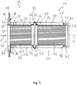
- An exhaust gas treatment assembly for an exhaust system of an internal combustion engine, for example in a vehicle, is generally designated 10 .
- the exhaust gas treatment assembly comprises a tubular housing 12 that is elongated in the direction of a housing longitudinal axis L and constructed, for example, with sheet metal material 1
- a connecting flange region 16 protrudes radially outwards from a housing wall 14 that is essentially cylindrical in long regions, with which flange region 16 the housing 12 is connected, for example by welding, to a base or a wall 18 of an exhaust gas-carrying housing or an exhaust gas-carrying component of a Exhaust system 19 can be fixed.
- the end region of the housing 12 shown on the left and connected to the wall 18 has an insertion opening 20 which is aligned with an opening 22 in the wall 18, so that through the opening 22 and the insertion opening 20 in the manner described below a first Exhaust treatment unit 24 and a second exhaust treatment unit 26 can be inserted into the housing 12 .
- the first exhaust gas treatment unit 24 comprises, for example, a tubular, essentially cylindrical first casing 28 in which a first exhaust gas treatment element 32 is held, for example by means of a fiber mat 30 or the like.
- the first exhaust gas treatment element 32 can comprise a body, for example monolithic, porous or through which the exhaust gas can flow, which can be constructed and/or coated with catalytically active material.
- the locking arrangement 52 comprises a plurality of locking engagement elements 54, which are preferably arranged at a uniform circumferential distance from one another about the longitudinal axis L of the housing, and a locking engagement recess 56 that runs completely around the longitudinal axis L of the housing in the exemplary embodiment shown the forming of the wall 14 of the housing 12 constructed with sheet metal material can be provided.
- the locking engagement recess 56 can be provided in that the wall thickness of the wall 14 of the housing 12 is reduced in the area of this locking engagement recess 56 .
- Each of the locking engagement elements 54 which are made of sheet metal, for example, and are therefore basically elastically deformable or flexible, is fixed with a fixing section 58 on the first jacket 28 in the region of the second end section 50 of the first exhaust gas treatment unit 24 .
- This can for example by material connection such. B. soldering or welding, or by a Fastener such. B. a fastening rivet or several fastening rivets or the like.
- at least one or each of the locking engagement members 54 could form an integral part of the first casing 28 and, starting from a region of the integral connection to the first casing 28 that provides the fixing section 58, extend radially outwards.
- the locking engagement elements 54 are configured as components that are separate from the first jacket 28 and are fixed to it, these extend, starting from their fixing section 58, with a locking section 60 radially outwards, wherein in the in 1 shown locking state of the locking portion 60 is positioned engagingly in the locking engagement recesses 56 of the housing 12 and thus an axial movement of the first delivery action unit 24 in the housing 12 by acting in the direction of the housing longitudinal axis L form fit prevented.
- a radially outer apex area of blocking section 60 preferably lies in an apex area of locking engagement recess 56 and is in firm contact with housing 12, so that even minor movements of first exhaust gas treatment unit 24 in the direction of longitudinal housing axis L are prevented and a movement caused by vibrations in locking engagement organs 54 Hitting or rattling the same against the housing 12 does not occur.
- a support/sealing arrangement 72 is also provided in association therewith.
- This also comprises a sealing element 74, for example O-ring-like, a radial support element 76 and a ring-like axial support element 78, for example fixed on the outer circumference of the second jacket 34, for example by welding or soldering, which seals the sealing element 74 and the radial support element 76 counter to the direction of insertion E when the second Exhaust gas treatment unit 26 holds in the housing 12 in a defined positioning with respect to the second shell 34 .
- the first exhaust gas treatment unit 26 When the exhaust gas treatment unit 10 is assembled, first the first exhaust gas treatment unit 26 is inserted in the insertion direction E through the insertion opening 20 into the housing 12 .
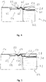
- the state in which the first exhaust treatment unit 24 is inserted into the case 12 but the second exhaust treatment unit 26 is not yet inserted into the case 12 is in 2 shown.
- the locking arrangement 52 or the locking engagement elements 54 are designed in such a way that their locking sections 60 do not engage in the locking engagement recess 56 .
- the locking engagement elements 54 do not rub with their blocking sections 60 along the inner surface of the wall 14 of the housing 12 .
- the second exhaust gas treatment unit 26 acts on the insertion end sections 80 and thus presses the locking engagement elements 54 with their locking sections 60 radially outwards, so that they engage in the locking engagement recess 56 and are held in contact with the housing 12 in the region of the locking engagement recess 56 are. Subsequently, the second exhaust gas treatment unit 26 can be fixed by the fastening elements 70 on the wall 18 and thus with respect to the housing 12 also carried thereon.
- the locking engagement elements 54 are blocked in the region of their blocking sections 62 against movement radially inward or are urged to engage in the locking engagement recess 56 in the radially outward direction, the locking arrangement 52 is blocked in its locked state and thus the first exhaust gas treatment unit 24 in defined axial positioning on the housing 12 held.
- a defined radial support of the first exhaust gas treatment unit 24 with respect to the housing 12 is thereby also achieved in the second end section 50 of the first exhaust gas treatment unit 24 .
- the locking engagement elements 54 can at least support the defined radial mounting of the second exhaust gas treatment unit 26 in its first end section 64 .
- the locking engagement elements 54 can be held with their locking sections 60 in contact with the housing 12 in the area of the locking engagement recess 56 solely because of the shape and thus pretension. It is not absolutely necessary for the blocking sections 62 to already be in contact with the second casing 34 in this state or for them to be acted upon radially outwards by the latter. However, the distance between the blocking portions 62 and the second shell 34 must be dimensioned such that upon movement of the Blocking sections 62 radially inwards, the locking sections 60 cannot disengage from the locking engagement recess 56 .
- exhaust gas treatment assembly 10 can also be used in such an exhaust gas treatment assembly 10 .
- another exhaust gas treatment unit may be positioned to the right of the first exhaust gas treatment unit 24 .
- a locking arrangement 52 as shown in FIG 1 is shown. This locking arrangement 52 can then be blocked in its locked state by the first exhaust gas treatment unit 24 , while in turn the locking arrangement 52 of the first exhaust gas treatment unit 24 can be locked in its locked state by the second exhaust gas treatment unit 26 .
- the inwardly open detent engagement recess 56 is on the housing 12 therethrough provided that at an axial distance from one another there are protrusions 61, 63 of the housing which are directed radially inwards, for example in the circumferential direction completely or are limited in the circumferential direction, which between them form the locking engagement recess 56 which is open radially inwards for receiving a locking engagement element 54. In this way, formations directed radially outwards and thus locally increasing the diameter of the housing can essentially be avoided.
- FIG. 5 Another alternative embodiment of the locking arrangement 52 is in figure 5 shown.
- a locking engagement projection 59 is provided on the housing 12 , formed by forming, for example, completely circumferential in the circumferential direction or provided by sections limited in the circumferential direction and directed radially inward or protruding radially inward.
- a radially outwardly open locking engagement recess 57 is formed on each locking member 54, for example between two rib-like formations.
- the locking element 54 which is prestressed radially outwards or is loaded radially outwards by the second exhaust gas treatment unit 26, engages in the region of its locking engagement recess 57, which is open radially outwards, or a locking engagement projection 59 protruding radially inwards on the housing 12, as a result of which the first exhaust gas treatment unit 24 axially is fixed with respect to the housing 12 and is also blocked against loosening when the second exhaust gas treatment unit 24 is inserted into the housing 12 in this state.
- FIG. 6 An alternative embodiment for connecting the locking elements 54 to the first casing 28 is shown in 6 shown.
- the locking elements 54 are provided on a ring-like locking element carrier 65 formed, for example, from sheet metal material, as integral components thereof.
- the Arresting element carrier 65 can be fixed in the region of second end section 50 of first exhaust gas treatment unit 24 on first jacket 28 , for example surrounding it on the outside or inserted into it, as a result of which all arresting elements 54 can be firmly attached to first jacket 28 .
- an exhaust gas treatment assembly achieves a simple and reliable locking or fixing of the exhaust gas treatment unit, in which production tolerances and thermal expansions can also be compensated for in the axial direction and in the radial direction due to the flexibility in the area of the locking engagement elements.
- the locking engagement members can also be used as handles when handling the first exhaust treatment unit.
- both exhaust gas treatment units can each be designed as catalytic converter units.
- one of the exhaust gas treatment units can be designed as a catalytic converter unit and the other as a particle filter unit.
- one of the exhaust gas treatment units can be a heating unit operated, for example, by electrical excitation, through which heat can be introduced into the exhaust gas flow or in an exhaust gas treatment element and thus exhaust gas treatment in the form of heat input is implemented.
- a combination of an exhaust gas treatment unit designed as a catalytic converter unit and an exhaust gas treatment unit designed as a heating unit could be provided.
- an exhaust gas treatment unit designed as a heating unit with an exhaust gas treatment unit designed as a particle filter unit could be implemented.
- an exhaust gas treatment unit in addition to an exhaust gas treatment element that is effective, for example, as a catalyst or particle filter, an exhaust gas treatment unit could also be provided with an electrically excitable heating element, for example, so that this exhaust gas treatment unit can be effective both as a heating unit and as a catalyst unit or particle filter unit can.
- a line bushing for supplying electrical energy to a heating element for example a sheathed heating conductor, must be provided through the housing.
Landscapes
- Engineering & Computer Science (AREA)
- Chemical & Material Sciences (AREA)
- Chemical Kinetics & Catalysis (AREA)
- Combustion & Propulsion (AREA)
- Mechanical Engineering (AREA)
- General Engineering & Computer Science (AREA)
- Health & Medical Sciences (AREA)
- Toxicology (AREA)
- Exhaust Gas After Treatment (AREA)
Applications Claiming Priority (2)
| Application Number | Priority Date | Filing Date | Title |
|---|---|---|---|
| DE102021102551 | 2021-02-04 | ||
| DE102021104678.5A DE102021104678A1 (de) | 2021-02-26 | 2021-02-26 | Abgasbehandlungsbaugruppe für eine Abgasanlage einer Brennkraftmaschine |
Publications (1)
| Publication Number | Publication Date |
|---|---|
| EP4039952A1 true EP4039952A1 (fr) | 2022-08-10 |
Family
ID=79230746
Family Applications (1)
| Application Number | Title | Priority Date | Filing Date |
|---|---|---|---|
| EP22150107.5A Pending EP4039952A1 (fr) | 2021-02-04 | 2022-01-04 | Module de traitement des gaz d'échappement pour un syst?me d'échappement des gaz d'un moteur à combustion interne |
Country Status (3)
| Country | Link |
|---|---|
| US (1) | US11795860B2 (fr) |
| EP (1) | EP4039952A1 (fr) |
| CN (1) | CN114856785B (fr) |
Families Citing this family (1)
| Publication number | Priority date | Publication date | Assignee | Title |
|---|---|---|---|---|
| FR3128485A1 (fr) * | 2021-10-25 | 2023-04-28 | Faurecia Systemes D'echappement | Elément chauffant pour ligne d’échappement |
Citations (2)
| Publication number | Priority date | Publication date | Assignee | Title |
|---|---|---|---|---|
| DE3908887A1 (de) * | 1989-03-17 | 1990-09-20 | Eberspaecher J | Vorrichtung zur katalytischen entgiftung oder dgl. von verbrennungsmotor-abgasen mit zwei abgas-behandlungskoerpern und einem schutzring dazwischen |
| WO2009096641A1 (fr) * | 2008-01-31 | 2009-08-06 | Suk Man Song | Système de filtrage des gaz d'échappement pour véhicules |
Family Cites Families (9)
| Publication number | Priority date | Publication date | Assignee | Title |
|---|---|---|---|---|
| DE2243251B2 (de) * | 1972-09-02 | 1976-01-02 | Paul Gillet Gmbh, 6732 Edenkoben | Vorrichtung zur Reinigung der Abgase von Brennkraftmaschinen |
| JPS59215914A (ja) * | 1983-05-24 | 1984-12-05 | Honda Motor Co Ltd | 二段触媒コンバ−タ |
| FR2839533B1 (fr) * | 2002-05-07 | 2004-11-19 | Faurecia Sys Echappement | Dispositif nettoyable de depollution des gaz d'echappement d'un moteur |
| SE0301876L (sv) | 2003-06-26 | 2004-05-04 | Scania Cv Abp | Låsanordning för montering av åtminstone en avgasrenande komponent i en avgaspassage |
| FR2879240B1 (fr) * | 2004-12-10 | 2010-12-17 | Faurecia Sys Echappement | Dispositif de depollution des gaz d'echappement d'un moteur thermique |
| EP2110528B2 (fr) * | 2008-04-18 | 2017-04-19 | Daimler AG | Dispositif pour le traitement d'un flux de gaz d'échappement doté d'un module amovible |
| DE102009007391A1 (de) * | 2009-02-05 | 2010-08-12 | J. Eberspächer GmbH & Co. KG | Abgasreinigungseinrichtung, Abgasanlage und Schellenverbindung |
| DE102013015602A1 (de) * | 2013-08-28 | 2015-03-05 | Mtu Friedrichshafen Gmbh | Abgasnachbehandlungssystem für eine Brennkraftmaschine und Brennkraftmaschine |
| DE102015209681B4 (de) | 2015-05-27 | 2023-05-17 | Purem GmbH | Abgasbehandlungseinrichtung mit austauschbarem Einsatz |
-
2022
- 2022-01-04 EP EP22150107.5A patent/EP4039952A1/fr active Pending
- 2022-01-30 CN CN202210113172.4A patent/CN114856785B/zh active Active
- 2022-02-04 US US17/665,008 patent/US11795860B2/en active Active
Patent Citations (2)
| Publication number | Priority date | Publication date | Assignee | Title |
|---|---|---|---|---|
| DE3908887A1 (de) * | 1989-03-17 | 1990-09-20 | Eberspaecher J | Vorrichtung zur katalytischen entgiftung oder dgl. von verbrennungsmotor-abgasen mit zwei abgas-behandlungskoerpern und einem schutzring dazwischen |
| WO2009096641A1 (fr) * | 2008-01-31 | 2009-08-06 | Suk Man Song | Système de filtrage des gaz d'échappement pour véhicules |
Also Published As
| Publication number | Publication date |
|---|---|
| CN114856785B (zh) | 2024-06-11 |
| CN114856785A (zh) | 2022-08-05 |
| US11795860B2 (en) | 2023-10-24 |
| US20220243639A1 (en) | 2022-08-04 |
Similar Documents
| Publication | Publication Date | Title |
|---|---|---|
| EP2372209B1 (fr) | Conduite de gaz d'échappement pour un véhicule automobile et installation de traitement des gaz d'échappement | |
| EP1629573B1 (fr) | Raccord electrique a parties enfichables | |
| DE102015209681B4 (de) | Abgasbehandlungseinrichtung mit austauschbarem Einsatz | |
| DE112011102044T5 (de) | Verbesserte Einrast-Mitteldichtungsbuchse | |
| EP3626951A1 (fr) | Clapet d'échappement | |
| EP3091306B1 (fr) | Chauffage pour vehicule | |
| DE102013112542A1 (de) | Getriebebaugruppe für eine elektromechanische Servolenkung | |
| EP3549663B1 (fr) | Installation de gaz d'échappement et module mélangeur pour une installation de gaz d'échappement | |
| EP1422396B1 (fr) | catalyseur à lits multiples | |
| EP2252752B1 (fr) | Dispositif permettant de réaliser une connexion électrique sèche d'une serrure de véhicule automobile | |
| WO2019201543A1 (fr) | Collier de serrage | |
| DE102013223241A1 (de) | Wärmeträgermediumanschlussbaugruppe, insbesondere für eine Wärmetauscheranordnung eines Fahrzeugheizgeräts | |
| DE29916158U1 (de) | Katalytischer Konverter zum Reinigen von Abgas und Abgasreinigungsanordnung mit einem katalytischen Konverter | |
| DE102016120171A1 (de) | Mischerbaugruppe | |
| DE102021104678A1 (de) | Abgasbehandlungsbaugruppe für eine Abgasanlage einer Brennkraftmaschine | |
| EP2034150A1 (fr) | Procédé d'attachement d'un capteur a une dispositif de traitement de gaz d'échappement | |
| DE102008028393A1 (de) | Frischluftanlage und Kupplungseinrichtung | |
| EP4253735B1 (fr) | Système d'échappement pour tracteur | |
| EP1818591B1 (fr) | Elément de conduite avec soufflet et manchon tressé fixé au soufflet par un élément annulaire | |
| EP3772574B1 (fr) | Module de traitement des gaz d'échappement | |
| DE102022111864A1 (de) | Heizvorrichtung | |
| DE2341265A1 (de) | Einrichtung zur katalytischen abgasreinigung | |
| EP4108890A1 (fr) | Silencieux et procédé de fabrication d'un silencieux | |
| EP4047192B1 (fr) | Module d'appui pour supporter un élément de traitement des gaz d'échappement logé dans un boîtier | |
| EP3907383A1 (fr) | Dispositif de chauffage à gaz d'échappement pour une installation de gaz d'échappement d'un moteur à combustion interne |
Legal Events
| Date | Code | Title | Description |
|---|---|---|---|
| PUAI | Public reference made under article 153(3) epc to a published international application that has entered the european phase |
Free format text: ORIGINAL CODE: 0009012 |
|
| STAA | Information on the status of an ep patent application or granted ep patent |
Free format text: STATUS: THE APPLICATION HAS BEEN PUBLISHED |
|
| AK | Designated contracting states |
Kind code of ref document: A1 Designated state(s): AL AT BE BG CH CY CZ DE DK EE ES FI FR GB GR HR HU IE IS IT LI LT LU LV MC MK MT NL NO PL PT RO RS SE SI SK SM TR |
|
| STAA | Information on the status of an ep patent application or granted ep patent |
Free format text: STATUS: REQUEST FOR EXAMINATION WAS MADE |
|
| 17P | Request for examination filed |
Effective date: 20230130 |
|
| RBV | Designated contracting states (corrected) |
Designated state(s): AL AT BE BG CH CY CZ DE DK EE ES FI FR GB GR HR HU IE IS IT LI LT LU LV MC MK MT NL NO PL PT RO RS SE SI SK SM TR |
|
| STAA | Information on the status of an ep patent application or granted ep patent |
Free format text: STATUS: EXAMINATION IS IN PROGRESS |
|
| 17Q | First examination report despatched |
Effective date: 20230817 |