EP4039963B1 - Vorspannsystem für einen aktuator - Google Patents
Vorspannsystem für einen aktuator Download PDFInfo
- Publication number
- EP4039963B1 EP4039963B1 EP21155949.7A EP21155949A EP4039963B1 EP 4039963 B1 EP4039963 B1 EP 4039963B1 EP 21155949 A EP21155949 A EP 21155949A EP 4039963 B1 EP4039963 B1 EP 4039963B1
- Authority
- EP
- European Patent Office
- Prior art keywords
- lock sleeve
- lock
- tine
- finger
- tine finger
- Prior art date
- Legal status (The legal status is an assumption and is not a legal conclusion. Google has not performed a legal analysis and makes no representation as to the accuracy of the status listed.)
- Active
Links
Images
Classifications
-
- F—MECHANICAL ENGINEERING; LIGHTING; HEATING; WEAPONS; BLASTING
- F16—ENGINEERING ELEMENTS AND UNITS; GENERAL MEASURES FOR PRODUCING AND MAINTAINING EFFECTIVE FUNCTIONING OF MACHINES OR INSTALLATIONS; THERMAL INSULATION IN GENERAL
- F16F—SPRINGS; SHOCK-ABSORBERS; MEANS FOR DAMPING VIBRATION
- F16F1/00—Springs
- F16F1/02—Springs made of steel or other material having low internal friction; Wound, torsion, leaf, cup, ring or the like springs, the material of the spring not being relevant
-
- F—MECHANICAL ENGINEERING; LIGHTING; HEATING; WEAPONS; BLASTING
- F02—COMBUSTION ENGINES; HOT-GAS OR COMBUSTION-PRODUCT ENGINE PLANTS
- F02K—JET-PROPULSION PLANTS
- F02K1/00—Plants characterised by the form or arrangement of the jet pipe or nozzle; Jet pipes or nozzles peculiar thereto
- F02K1/54—Nozzles having means for reversing jet thrust
- F02K1/76—Control or regulation of thrust reversers
- F02K1/763—Control or regulation of thrust reversers with actuating systems or actuating devices; Arrangement of actuators for thrust reversers
-
- F—MECHANICAL ENGINEERING; LIGHTING; HEATING; WEAPONS; BLASTING
- F02—COMBUSTION ENGINES; HOT-GAS OR COMBUSTION-PRODUCT ENGINE PLANTS
- F02K—JET-PROPULSION PLANTS
- F02K1/00—Plants characterised by the form or arrangement of the jet pipe or nozzle; Jet pipes or nozzles peculiar thereto
- F02K1/54—Nozzles having means for reversing jet thrust
- F02K1/76—Control or regulation of thrust reversers
- F02K1/766—Control or regulation of thrust reversers with blocking systems or locking devices; Arrangement of locking devices for thrust reversers
-
- F—MECHANICAL ENGINEERING; LIGHTING; HEATING; WEAPONS; BLASTING
- F05—INDEXING SCHEMES RELATING TO ENGINES OR PUMPS IN VARIOUS SUBCLASSES OF CLASSES F01-F04
- F05D—INDEXING SCHEME FOR ASPECTS RELATING TO NON-POSITIVE-DISPLACEMENT MACHINES OR ENGINES, GAS-TURBINES OR JET-PROPULSION PLANTS
- F05D2260/00—Function
- F05D2260/30—Retaining components in desired mutual position
- F05D2260/38—Retaining components in desired mutual position by a spring, i.e. spring loaded or biased towards a certain position
Definitions
- the present disclosure relates to a biasing system for an actuator.
- a tine lock and lock sleeve is typically used in an actuator for a thrust reverser. After deployment, the lock may have difficulty in returning to a stowed and locked position. Certain failures in the door locking actuator can lead to the lock sleeve inadvertently returning to the locked position prior to the door fully stowing and the tine lock being engaged. The tine lock is then unable to engage but the system will signal locked as the position of the lock sleeve is sensed, not the position of the door.
- a biasing system for an actuator comprises a lock sleeve, a lock shaft, a tine having a tine finger extending along a longitudinal axis, a biasing member and a biasing spring.
- the biasing member and biasing spring are configured to maintain a position of the tine finger away from the longitudinal axis in the direction of the lock sleeve such that, when the lock sleeve is returned, the tine finger is biased against the lock sleeve to prevent the lock sleeve from returning to a locked position before the lock shaft.
- the lock sleeve may include a first surface and a second surface.
- the tine finger may include a first surface, a second surface, a third surface and a protrusion.
- the lock shaft may include a first surface, a second surface and a third surface.
- the biasing member may include a first end.
- the biasing system may further include a locked position, an intermediate position and a transition position.
- the tine finger in a locked position, may be in a relaxed state and may be sandwiched between the first surface of the lock shaft and the first surface of the lock sleeve.
- the tine finger may be parallel to the longitudinal axis.
- the first end of the biasing member may be in contact with the second surface of the lock shaft such that the biasing spring is held in a compressed state by the second surface of the lock shaft.
- the lock sleeve in an intermediate position, the lock sleeve may be deployed, in use, and the third surface of the lock shaft may be configured to engage the protrusion of the tine finger such that the tine finger may move in a direction away from the longitudinal axis towards the lock sleeve.
- the tine finger in a transition position, may be biased in a direction away from the longitudinal axis towards the lock sleeve by the biasing member, and wherein, when the lock sleeve returns, in use, the third surface of the tine finger may contact the second surface of the lock sleeve to prevent the lock sleeve to move to a closed/locked position.
- An actuator includes the biasing system as described above.
- a thrust reverser includes the actuator.
- a method for biasing a lock sleeve in an actuator comprises providing a tine having a tine finger extending along a longitudinal axis and wherein the tine finger is in a relaxed state and wherein the tine finger is sandwiched between a lock sleeve and a lock shaft in a locked position, deploying the lock sleeve and lock shaft along a longitudinal axis away from the tine such that the tine finger is not in contact with the lock sleeve and the lock shaft, biasing the tine finger in a direction perpendicular to the longitudinal axis and towards the lock sleeve, wherein, when the lock sleeve returns, the tine finger is biased against the lock sleeve to prevent the lock sleeve from returning to a locked position before the lock shaft.
- the lock sleeve may include a first surface and a second surface.
- the tine finger may include a first surface, a second surface, a third surface and a protrusion.
- the lock shaft may include a first surface, a second surface and a third surface.
- the biasing member may include a first end.
- the method may further include a locked position, an intermediate position and a transition position.
- the tine finger in a locked position, may be in a relaxed state and may be sandwiched between the first surface of the lock shaft and the first surface of the lock sleeve.
- the tine finger may be parallel to the longitudinal axis.
- the first end of the biasing member may be in contact with the second surface of the lock shaft such that the biasing spring may be held in a compressed state by the second surface of the lock shaft.
- the lock sleeve in an intermediate position, the lock sleeve may be deployed, in use, and the third surface of the lock shaft may engage the protrusion of the tine finger such that the tine finger may move in a direction away from the longitudinal axis towards the lock sleeve.
- the tine finger in a transition position, may be biased in a direction away from the longitudinal axis towards the lock sleeve by the biasing member, and wherein, when the lock sleeve returns, in use, the third surface of the tine finger may contact the second surface of the lock sleeve to prevent the lock sleeve to move to a closed/locked position.
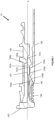
- Figure 1 shows an exemplary view of a portion of an actuator 10 in a stowed and locked position.
- the portion of the actuator 10 may include a tine 100, a tine finger 101, a lock sleeve 120, a lock shaft 130, a biasing member 142 (e.g. a baulk) and a biasing spring 140 (e.g. a baulk spring).
- the tine finger 101 is in a relaxed state and engages the lock sleeve 120 and the lock shaft 130, such that the tine finger 101 is sandwiched between the lock sleeve 120 and the lock shaft 130.
- the biasing member 142 is engaged with the lock shaft 130 such that the lock shaft 130 acts to maintain the biasing member 142 and biasing spring 140 in a compressed state.
- FIG. 1 An exemplary actuator 10 is shown in Figure 1 .
- the arrangement of the actuator 10 is shown for exemplary purposes only and, of course, it is envisaged that the tine 100, tine finger 101, lock sleeve 120, lock shaft 130, biasing member 142 and biasing spring 140 may be arranged in a different manner to achieve the same result.
- the lock sleeve 120 may include a first surface 120a and a second surface 120b.
- the tine finger 101 may include a first surface 101a, a second surface 101b and a third surface 101c.
- the lock shaft 130 may include a first surface 130a, a second surface 130b and a third surface 130c.
- the biasing member 142 may have a first end 142a.
- the portion of the actuator 10 has a longitudinal axis, as shown by dotted line A.
- the tine finger 101 As the tine finger 101 is in a relaxed state in Figure 1 , the tine finger 101 lies in parallel with the longitudinal axis A. In a locked position, the first surface 101a of the tine finger 101 is adjacent the first surface 120a of the lock sleeve 120. The second surface 101b of the tine finger 101 is adjacent the first surface 130a of the lock shaft 130. Therefore, the tine finger 101 is sandwiched between the first surface 120a of the lock sleeve 120 and the first surface 130a of the lock shaft 130, which maintains the position of the tine finger 101, along the longitudinal axis A, in a locked position.
- the first end 142a of the biasing member 142 is in contact with the second surface 130b of the lock shaft 130.
- the biasing spring 140 is held in a compressed state by the first end 142a of the biasing member 142 being in contact with the second surface 130b of the lock shaft 130.
- the lock shaft 130 is holding the biasing member 142 and biasing spring 140 in place until the lock shaft 130 moves out of a locked position.
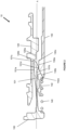
- Figure 2 shows an exemplary view of a portion of the actuator 10 in an intermediate position.
- the lock sleeve 120 has moved in a longitudinal direction away from the tine finger 101.
- the lock shaft 130 has also moved in a longitudinal direction and has engaged with the tine finger 101 to displace the tine finger 101 in a direction towards the lock sleeve 120.
- the biasing spring 140 expands and moves the biasing member 142 towards the tine finger 101.
- the exemplary actuator 10 of Figure 1 in an intermediate position is shown in Figure 2 .
- the arrangement of the actuator 10 is shown for exemplary purposes only and, of course, it is envisaged that the tine 100, tine finger 101, lock sleeve 120, lock shaft 130, biasing member 142 and biasing spring 140 may be arranged in a different manner to achieve the same result.
- the lock sleeve 120 may include the first surface 120a and the second surface 120b.
- the tine finger 101 may include the first surface 101a, the second surface 101b, the third surface 101c and a protrusion 101d.
- the lock shaft 130 may include the first surface 130a, the second surface 130b and the third surface 130c.
- the biasing member 142 may include the first end 142a.
- the portion of the actuator 10 includes the longitudinal axis, as shown by dotted line A.
- the lock sleeve 120 In the intermediate position, the lock sleeve 120 has moved in a direction along the longitudinal axis A away from the tine 100.
- the first surface 101a of the tine finger 101 is now not adjacent the first surface 120a of the lock sleeve 120 and is free to move in a perpendicular direction away from the longitudinal axis A.
- the lock shaft 130 translates along the longitudinal axis A, the first surface 130a of the lock shaft 130 moves alongside the second surface 101b of the tine finger 101 and the third surface 130c of the lock shaft 130 is configured to engage with the protrusion 101d.
- the third surface 130c of the lock shaft 130 therefore forces the protrusion 101d of the tine finger 101, and in turn the tine finger 101, in a perpendicular direction away from the longitudinal axis A towards the lock sleeve 120.
- the first end 142a of the biasing member 142 also translates along the longitudinal axis A by virtue of the biasing member 142 being in contact with the second surface 130b of the lock shaft 130 and the spring decompressing as the lock shaft 130 translates along the longitudinal axis A.
- the biasing member 142 is shaped such that it maintains the position of the tine finger 101 in a deformed state after the lock shaft 130 has been deployed and the first end 142a of the biasing member 142 is no longer engaged with the second surface 130b of the lock shaft 130.
- the first end 142a of the biasing member 142 may contact the second surface 101b and the protrusion 101d of the tine finger 101 to stop the tine finger 101 from returning to a relaxed state (shown in more detail in Figure 3 ).
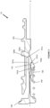
- FIG 3 shows an exemplary view of a portion of the actuator 10 in a transition position.
- a transition position for the purposes of the example of Figure 3 , is a position in which the lock sleeve 120 is returning in a direction along the longitudinal axis A toward the tine finger 101.
- the lock shaft has fully deployed and is no longer in view on Figure 3 .
- the biasing spring 140 is now in a fully expanded state and the biasing member 142 is engaged with the tine finger 101 to maintain the position of the tine finger 101.
- the lock sleeve 120 has returned and the position of the tine finger 101, being held by the biasing member 142, prevents the lock sleeve 120 from fully retracting into the actuator.
- the tine finger 101 engages with the lock sleeve 120 such that the lock sleeve 120 cannot be restored to a locked position.
- This entire mechanism therefore allows the lock shaft 130 (not shown in Figure 3 ) to return to a locked position (as shown in Figure 1 ) before the lock sleeve 120 is able to return to a locked position.
- the lock shaft 130 again engages with and moves the biasing member 142 and compresses the biasing spring 140 such that the tine finger 101 can move back to a relaxed state and be, once again, sandwiched between the lock sleeve 120 and lock shaft 130.
- the exemplary actuator 10 of Figures 1 and 2 in a transition position is shown in Figure 3 .
- the arrangement of the actuator 10 is shown for exemplary purposes only and, of course, it is envisaged that the tine 100, tine finger 101, lock sleeve 120, lock shaft 130, biasing member 142 and biasing spring 140 may be arranged in a different manner to achieve the same result.
- the lock sleeve 120 may include the first surface 120a and the second surface 120b.
- the tine finger 101 may include the first surface 101a, the second surface 101b, the third surface 101c and the protrusion 101d.
- the biasing member 142 may include the first end 142a.
- the portion of the actuator 10 includes the longitudinal axis, as shown by dotted line A.
- the lock shaft 130 has completely deployed.
- the lock sleeve 120 has returned.
- the lock sleeve 120 may or may not be present in Figure 3 and the biasing member 142 may be acting on the tine finger 101 to be positioned in a direction away from the longitudinal axis A to mate with the lock sleeve 120 when it returns.
- FIG. 3 depicts the lock sleeve 120 returned from an unlocked to a near-closed position.
- the third surface 101c of the tine finger 101 contacts the second surface 120b of the lock sleeve 120.
- the arrangement of the tine finger 101 being biased by the biasing member 142 allows the tine finger 101 to stop the movement of the lock sleeve 120 to a closed/locked position, which can result in false readings of the actuator 10 being returned to a fully closed/locked position before the lock shaft 130 has returned fully.
- the lock shaft 130 (not shown in Figure 3 ) returns, the second surface 130b of the lock shaft 130 will once again contact the biasing member 142 and biasing spring 140.
- the lock shaft 130 will therefore compress the biasing spring 140 and move the biasing member 142 along the longitudinal direction towards the tine 100.
- the second surface 101b and protrusion 101d of the tine finger 101 will then be able to move to a relaxed state, as the first surface 130a and third surface 130c of the lock shaft 130 passes until the lock shaft 130 has fully returned.
- the second surface 101b of the tine finger 101 will be adjacent the second surface 130b of the lock shaft 130 and will be sandwiched between the first surface 120a of the lock sleeve 120 and the first surface 130a of the lock shaft 130, as shown in Figure 1 .
- the exemplary biasing system described above may result in lighter, cheaper and more reliable system architectures.
- ordinary switches may be removed by the inclusion of the biasing system.
Landscapes
- Engineering & Computer Science (AREA)
- General Engineering & Computer Science (AREA)
- Mechanical Engineering (AREA)
- Chemical & Material Sciences (AREA)
- Combustion & Propulsion (AREA)
- Lock And Its Accessories (AREA)
- Mutual Connection Of Rods And Tubes (AREA)
Claims (14)
- Vorspannsystem für einen Aktuator, wobei das System Folgendes umfasst:eine Verriegelungshülse (120);eine Verriegelungswelle (130);einen Zinken (100), der einen Zinkenfinger (101) aufweist, der sich entlang einer Längsachse erstreckt;ein Vorspannelement (142) und eine Vorspannfeder (140), wobei das Vorspannelement (142) und die Vorspannfeder (140) dazu konfiguriert sind, eine Position des Zinkenfingers (101) von der Längsachse weg in der Richtung der Verriegelungshülse beizubehalten, wenn die Verriegelungshülse (120) und die Verriegelungswelle (130) in Verwendung ausgefahren sind, und wobei, wenn die Verriegelungshülse (120) zurückgestellt wird, der Zinkenfinger (101) gegen die Verriegelungshülse (120) vorgespannt wird, um die Verriegelungshülse (120) daran zu hindern, vor der Verriegelungswelle (130) in eine verriegelte Position zurückzukehren.
- Vorspannsystem nach Anspruch 1, wobei die Verriegelungshülse (120) eine erste Fläche (120a) und eine zweite Fläche (120b) beinhaltet;wobei der Zinkenfinger (101) eine erste Fläche (101a), eine zweite Fläche (101b), eine dritte Fläche (101c) und einen Vorsprung (101d) beinhaltet;wobei die Verriegelungswelle (130) eine erste Fläche (130a), eine zweite Fläche (130b) und eine dritte Fläche (130c) beinhaltet; undwobei das Vorspannelement (142) ein erstes Ende (142a) beinhaltet.
- Vorspannsystem nach Anspruch 2, ferner umfassend eine verriegelte Position, eine Zwischenposition und eine Übergangsposition.
- Vorspannsystem nach Anspruch 3, wobei in einer verriegelten Position sich der Zinkenfinger (101) in einem entspannten Zustand befindet und zwischen der ersten Fläche (130a) der Verriegelungswelle (130) und der ersten Fläche (120a) der Verriegelungshülse (120) eingeschlossen ist, und wobei der Zinkenfinger (101) parallel zu der Längsachse ist; und
wobei das erste Ende (142a) des Vorspannelements (142) derart in Kontakt mit der zweiten Fläche (130b) der Verriegelungswelle (130) ist, dass die Vorspannfeder (140) durch die zweite Fläche (130b) der Verriegelungswelle (130) in einem zusammengedrückten Zustand gehalten ist. - Vorspannsystem nach Anspruch 3, wobei in einer Zwischenposition die Verriegelungshülse (120) in Verwendung ausgefahren ist und die dritte Fläche (130c) der Verriegelungswelle (130) dazu konfiguriert ist, in den Vorsprung (101d) des Zinkenfingers (101) derart einzugreifen, dass der Zinkenfinger (101) dazu konfiguriert ist, sich in einer Richtung von der Längsachse weg zu der Verriegelungshülse (120) hin zu bewegen.
- Vorspannsystem nach Anspruch 3, wobei in einer Übergangsposition der Zinkenfinger (101) durch das Vorspannelement (142) in einer Richtung von der Längsachse weg zu der Verriegelungshülse (120) hin vorgespannt ist, und wobei, wenn die Verriegelungshülse (120) zurückkehrt, in Verwendung die dritte Fläche (101c) des Zinkenfingers (101) die zweite Fläche (120b) der Verriegelungshülse (120) kontaktiert, um zu verhindern, dass sich die Verriegelungshülse (120) in eine geschlossene/verriegelte Position bewegt.
- Aktuator, der Folgendes umfasst:
das Vorspannsystem nach einem der vorhergehenden Ansprüche. - Schubumkehrvorrichtung, die den Aktuator nach Anspruch 7 umfasst.
- Verfahren zum Vorspannen einer Verriegelungshülse (120) in einem Aktuator, wobei das Verfahren Folgendes umfasst:Bereitstellen eines Zinkens (100), der einen Zinkenfinger (101) aufweist, der sich entlang einer Längsachse erstreckt, und wobei der Zinkenfinger in einem entspannten Zustand ist und wobei der Zinkenfinger zwischen einer Verriegelungshülse und einer Verriegelungswelle (130) in einer verriegelten Position eingeschlossen ist;Ausfahren der Verriegelungshülse und der Verriegelungswelle entlang einer Längsachse von dem Zinken weg derart, dass der Zinkenfinger mit der Verriegelungshülse und der Verriegelungswelle nicht in Kontakt ist;Vorspannen des Zinkenfingers in einer Richtung senkrecht zu der Längsachse und zu der Verriegelungshülse hin, wobei, wenn die Verriegelungshülse zurückkehrt, der Zinkenfinger gegen die Verriegelungshülse vorgespannt wird, um die Verriegelungshülse am Zurückkehren in eine verriegelte Position vor der Verriegelungswelle zu hindern.
- Verfahren nach Anspruch 9, wobei die Verriegelungshülse eine erste Fläche und eine zweite Fläche beinhaltet;wobei der Zinkenfinger eine erste Fläche, eine zweite Fläche, eine dritte Fläche und einen Vorsprung beinhaltet;wobei die Verriegelungswelle eine erste Fläche, eine zweite Fläche und eine dritte Fläche beinhaltet; undwobei das Vorspannelement ein erstes Ende beinhaltet.
- Verfahren nach Anspruch 10, ferner umfassend eine verriegelte Position, eine Zwischenposition und eine Übergangsposition.
- Verfahren nach Anspruch 11, wobei in einer verriegelten Position sich der Zinkenfinger in einem entspannten Zustand befindet und zwischen der ersten Fläche der Verriegelungswelle und der ersten Fläche der Verriegelungshülse eingeschlossen ist, und wobei der Zinkenfinger parallel zu der Längsachse ist; und wobei das erste Ende des Vorspannelements derart in Kontakt mit der zweiten Fläche der Verriegelungswelle ist, dass die Vorspannfeder durch die zweite Fläche der Verriegelungswelle in einem zusammengedrückten Zustand gehalten ist.
- Verfahren nach Anspruch 11, wobei in einer Zwischenposition die Verriegelungshülse in Verwendung ausgefahren ist und die dritte Fläche der Verriegelungswelle dazu konfiguriert ist, in den Vorsprung des Zinkenfingers derart einzugreifen, dass der Zinkenfinger dazu konfiguriert ist, sich in einer Richtung von der Längsachse weg zu der Verriegelungshülse hin zu bewegen.
- Verfahren nach Anspruch 11, wobei in einer Übergangsposition der Zinkenfinger durch das Vorspannelement in einer Richtung von der Längsachse weg zu der Verriegelungshülse hin vorgespannt ist, und wobei, wenn die Verriegelungshülse zurückkehrt, in Verwendung die dritte Fläche des Zinkenfingers die zweite Fläche der Verriegelungshülse kontaktiert, um zu verhindern, dass sich die Verriegelungshülse in eine geschlossene/verriegelte Position bewegt.
Priority Applications (4)
| Application Number | Priority Date | Filing Date | Title |
|---|---|---|---|
| EP21155949.7A EP4039963B1 (de) | 2021-02-09 | 2021-02-09 | Vorspannsystem für einen aktuator |
| CA3143726A CA3143726A1 (en) | 2021-02-09 | 2021-12-22 | A biasing system for an actuator |
| BR102022001439-6A BR102022001439A2 (pt) | 2021-02-09 | 2022-01-26 | Sistemas de desvio para um atuador e de polarização, atuador, reversor de empuxo, e, método para desviar uma luva de trava em um atuador |
| US17/586,003 US11988261B2 (en) | 2021-02-09 | 2022-01-27 | Biasing system for an actuator |
Applications Claiming Priority (1)
| Application Number | Priority Date | Filing Date | Title |
|---|---|---|---|
| EP21155949.7A EP4039963B1 (de) | 2021-02-09 | 2021-02-09 | Vorspannsystem für einen aktuator |
Publications (2)
| Publication Number | Publication Date |
|---|---|
| EP4039963A1 EP4039963A1 (de) | 2022-08-10 |
| EP4039963B1 true EP4039963B1 (de) | 2023-11-22 |
Family
ID=74572678
Family Applications (1)
| Application Number | Title | Priority Date | Filing Date |
|---|---|---|---|
| EP21155949.7A Active EP4039963B1 (de) | 2021-02-09 | 2021-02-09 | Vorspannsystem für einen aktuator |
Country Status (4)
| Country | Link |
|---|---|
| US (1) | US11988261B2 (de) |
| EP (1) | EP4039963B1 (de) |
| BR (1) | BR102022001439A2 (de) |
| CA (1) | CA3143726A1 (de) |
Family Cites Families (9)
| Publication number | Priority date | Publication date | Assignee | Title |
|---|---|---|---|---|
| US2887091A (en) * | 1958-01-28 | 1959-05-19 | Cleveland Pneumatic Ind Inc | Actuator finger lock |
| US2970573A (en) * | 1959-02-18 | 1961-02-07 | Gen Motors Corp | Actuator with stroke end locks |
| US3314335A (en) * | 1965-05-06 | 1967-04-18 | Gen Electric | Actuator locking mechanism |
| US3451313A (en) | 1967-06-21 | 1969-06-24 | Parker Hannifin Corp | Midstroke locking actuator |
| EP0801221A3 (de) * | 1996-04-09 | 1998-11-04 | Lucas Industries Public Limited Company | Betätigungssystem für eine Schubumkehrvorrichtung eines Flugzeugs |
| GB0813906D0 (en) | 2008-07-30 | 2008-09-03 | Goodrich Actuation Systems Ltd | Actuator |
| EP3164175B1 (de) * | 2014-07-01 | 2024-02-21 | Amgen Inc. | Autoinjektor mit niedrigenergiekolbenladung |
| EP3279458B1 (de) | 2016-08-04 | 2019-10-02 | Goodrich Actuation Systems Limited | Elektromagnetisch betätigtes zinkenschloss |
| EP3406888B1 (de) * | 2017-05-22 | 2022-03-23 | Goodrich Actuation Systems Limited | Aktuator |
-
2021
- 2021-02-09 EP EP21155949.7A patent/EP4039963B1/de active Active
- 2021-12-22 CA CA3143726A patent/CA3143726A1/en active Pending
-
2022
- 2022-01-26 BR BR102022001439-6A patent/BR102022001439A2/pt unknown
- 2022-01-27 US US17/586,003 patent/US11988261B2/en active Active
Also Published As
| Publication number | Publication date |
|---|---|
| CA3143726A1 (en) | 2022-08-09 |
| BR102022001439A2 (pt) | 2022-08-23 |
| EP4039963A1 (de) | 2022-08-10 |
| US11988261B2 (en) | 2024-05-21 |
| US20220252122A1 (en) | 2022-08-11 |
Similar Documents
| Publication | Publication Date | Title |
|---|---|---|
| US5547130A (en) | Lock for an engine thrust reverser | |
| CN110192046B (zh) | 带有被动锁定的致动器 | |
| EP3571384B1 (de) | Übertotpunkt-schubumkehrer-primärverriegelung | |
| EP0703358A2 (de) | Verriegelungsmechanismus für eine Schubumkehrvorrichtung | |
| EP3734004B1 (de) | Fahrzeugtürverschlussvorrichtung | |
| US5953904A (en) | Lock for engine thrust reverser | |
| EP4039963B1 (de) | Vorspannsystem für einen aktuator | |
| US10605199B2 (en) | Cylinder with integrated locking | |
| US10100561B2 (en) | Vehicular door handle with electrically deployable latch connection and overload compensating device | |
| US20200023991A1 (en) | Locking and unlocking mechanism | |
| US5041705A (en) | Cable-actuated emergency stop switch | |
| JP2004022549A (ja) | ロック可能なスイッチ機構 | |
| US11396933B2 (en) | Locking device for electromechanical actuator and electromechanical actuator comprising this device | |
| US12024925B2 (en) | Fast acting electro-mechanical unlocking device | |
| US10247285B2 (en) | Locking and unlocking mechanism for ram air turbine | |
| US6293489B1 (en) | Lock for a trust reverser | |
| US10012246B2 (en) | Failsafe deployment feature for actuator | |
| US6483062B1 (en) | Push-pull switch | |
| US4144816A (en) | Missile security mechanism | |
| EP0202734B1 (de) | Vorrichtung zum Ausfahren von Flossen | |
| US4182145A (en) | Key-operated locks | |
| US5610361A (en) | Primer detonation device and method | |
| EP3279093A1 (de) | Auslösemechanismus | |
| EP0290348B1 (de) | Festklemmbarer Riegelbolzen und damit ausgerüsteter Safe | |
| CN118774500A (zh) | 隐藏式门把手组件 |
Legal Events
| Date | Code | Title | Description |
|---|---|---|---|
| PUAI | Public reference made under article 153(3) epc to a published international application that has entered the european phase |
Free format text: ORIGINAL CODE: 0009012 |
|
| STAA | Information on the status of an ep patent application or granted ep patent |
Free format text: STATUS: THE APPLICATION HAS BEEN PUBLISHED |
|
| AK | Designated contracting states |
Kind code of ref document: A1 Designated state(s): AL AT BE BG CH CY CZ DE DK EE ES FI FR GB GR HR HU IE IS IT LI LT LU LV MC MK MT NL NO PL PT RO RS SE SI SK SM TR |
|
| STAA | Information on the status of an ep patent application or granted ep patent |
Free format text: STATUS: REQUEST FOR EXAMINATION WAS MADE |
|
| 17P | Request for examination filed |
Effective date: 20230201 |
|
| RBV | Designated contracting states (corrected) |
Designated state(s): AL AT BE BG CH CY CZ DE DK EE ES FI FR GB GR HR HU IE IS IT LI LT LU LV MC MK MT NL NO PL PT RO RS SE SI SK SM TR |
|
| GRAP | Despatch of communication of intention to grant a patent |
Free format text: ORIGINAL CODE: EPIDOSNIGR1 |
|
| STAA | Information on the status of an ep patent application or granted ep patent |
Free format text: STATUS: GRANT OF PATENT IS INTENDED |
|
| INTG | Intention to grant announced |
Effective date: 20230612 |
|
| GRAS | Grant fee paid |
Free format text: ORIGINAL CODE: EPIDOSNIGR3 |
|
| GRAA | (expected) grant |
Free format text: ORIGINAL CODE: 0009210 |
|
| STAA | Information on the status of an ep patent application or granted ep patent |
Free format text: STATUS: THE PATENT HAS BEEN GRANTED |
|
| AK | Designated contracting states |
Kind code of ref document: B1 Designated state(s): AL AT BE BG CH CY CZ DE DK EE ES FI FR GB GR HR HU IE IS IT LI LT LU LV MC MK MT NL NO PL PT RO RS SE SI SK SM TR |
|
| REG | Reference to a national code |
Ref country code: GB Ref legal event code: FG4D |
|
| REG | Reference to a national code |
Ref country code: CH Ref legal event code: EP |
|
| REG | Reference to a national code |
Ref country code: DE Ref legal event code: R096 Ref document number: 602021006929 Country of ref document: DE |
|
| REG | Reference to a national code |
Ref country code: IE Ref legal event code: FG4D |
|
| REG | Reference to a national code |
Ref country code: LT Ref legal event code: MG9D |
|
| REG | Reference to a national code |
Ref country code: NL Ref legal event code: MP Effective date: 20231122 |
|
| PG25 | Lapsed in a contracting state [announced via postgrant information from national office to epo] |
Ref country code: GR Free format text: LAPSE BECAUSE OF FAILURE TO SUBMIT A TRANSLATION OF THE DESCRIPTION OR TO PAY THE FEE WITHIN THE PRESCRIBED TIME-LIMIT Effective date: 20240223 |
|
| PG25 | Lapsed in a contracting state [announced via postgrant information from national office to epo] |
Ref country code: IS Free format text: LAPSE BECAUSE OF FAILURE TO SUBMIT A TRANSLATION OF THE DESCRIPTION OR TO PAY THE FEE WITHIN THE PRESCRIBED TIME-LIMIT Effective date: 20240322 |
|
| PG25 | Lapsed in a contracting state [announced via postgrant information from national office to epo] |
Ref country code: LT Free format text: LAPSE BECAUSE OF FAILURE TO SUBMIT A TRANSLATION OF THE DESCRIPTION OR TO PAY THE FEE WITHIN THE PRESCRIBED TIME-LIMIT Effective date: 20231122 |
|
| REG | Reference to a national code |
Ref country code: AT Ref legal event code: MK05 Ref document number: 1634061 Country of ref document: AT Kind code of ref document: T Effective date: 20231122 |
|
| PG25 | Lapsed in a contracting state [announced via postgrant information from national office to epo] |
Ref country code: NL Free format text: LAPSE BECAUSE OF FAILURE TO SUBMIT A TRANSLATION OF THE DESCRIPTION OR TO PAY THE FEE WITHIN THE PRESCRIBED TIME-LIMIT Effective date: 20231122 |
|
| PG25 | Lapsed in a contracting state [announced via postgrant information from national office to epo] |
Ref country code: AT Free format text: LAPSE BECAUSE OF FAILURE TO SUBMIT A TRANSLATION OF THE DESCRIPTION OR TO PAY THE FEE WITHIN THE PRESCRIBED TIME-LIMIT Effective date: 20231122 |
|
| PG25 | Lapsed in a contracting state [announced via postgrant information from national office to epo] |
Ref country code: ES Free format text: LAPSE BECAUSE OF FAILURE TO SUBMIT A TRANSLATION OF THE DESCRIPTION OR TO PAY THE FEE WITHIN THE PRESCRIBED TIME-LIMIT Effective date: 20231122 |
|
| PG25 | Lapsed in a contracting state [announced via postgrant information from national office to epo] |
Ref country code: NL Free format text: LAPSE BECAUSE OF FAILURE TO SUBMIT A TRANSLATION OF THE DESCRIPTION OR TO PAY THE FEE WITHIN THE PRESCRIBED TIME-LIMIT Effective date: 20231122 Ref country code: LT Free format text: LAPSE BECAUSE OF FAILURE TO SUBMIT A TRANSLATION OF THE DESCRIPTION OR TO PAY THE FEE WITHIN THE PRESCRIBED TIME-LIMIT Effective date: 20231122 Ref country code: IS Free format text: LAPSE BECAUSE OF FAILURE TO SUBMIT A TRANSLATION OF THE DESCRIPTION OR TO PAY THE FEE WITHIN THE PRESCRIBED TIME-LIMIT Effective date: 20240322 Ref country code: GR Free format text: LAPSE BECAUSE OF FAILURE TO SUBMIT A TRANSLATION OF THE DESCRIPTION OR TO PAY THE FEE WITHIN THE PRESCRIBED TIME-LIMIT Effective date: 20240223 Ref country code: ES Free format text: LAPSE BECAUSE OF FAILURE TO SUBMIT A TRANSLATION OF THE DESCRIPTION OR TO PAY THE FEE WITHIN THE PRESCRIBED TIME-LIMIT Effective date: 20231122 Ref country code: BG Free format text: LAPSE BECAUSE OF FAILURE TO SUBMIT A TRANSLATION OF THE DESCRIPTION OR TO PAY THE FEE WITHIN THE PRESCRIBED TIME-LIMIT Effective date: 20240222 Ref country code: AT Free format text: LAPSE BECAUSE OF FAILURE TO SUBMIT A TRANSLATION OF THE DESCRIPTION OR TO PAY THE FEE WITHIN THE PRESCRIBED TIME-LIMIT Effective date: 20231122 Ref country code: PT Free format text: LAPSE BECAUSE OF FAILURE TO SUBMIT A TRANSLATION OF THE DESCRIPTION OR TO PAY THE FEE WITHIN THE PRESCRIBED TIME-LIMIT Effective date: 20240322 |
|
| PG25 | Lapsed in a contracting state [announced via postgrant information from national office to epo] |
Ref country code: SE Free format text: LAPSE BECAUSE OF FAILURE TO SUBMIT A TRANSLATION OF THE DESCRIPTION OR TO PAY THE FEE WITHIN THE PRESCRIBED TIME-LIMIT Effective date: 20231122 Ref country code: RS Free format text: LAPSE BECAUSE OF FAILURE TO SUBMIT A TRANSLATION OF THE DESCRIPTION OR TO PAY THE FEE WITHIN THE PRESCRIBED TIME-LIMIT Effective date: 20231122 Ref country code: PL Free format text: LAPSE BECAUSE OF FAILURE TO SUBMIT A TRANSLATION OF THE DESCRIPTION OR TO PAY THE FEE WITHIN THE PRESCRIBED TIME-LIMIT Effective date: 20231122 Ref country code: NO Free format text: LAPSE BECAUSE OF FAILURE TO SUBMIT A TRANSLATION OF THE DESCRIPTION OR TO PAY THE FEE WITHIN THE PRESCRIBED TIME-LIMIT Effective date: 20240222 Ref country code: LV Free format text: LAPSE BECAUSE OF FAILURE TO SUBMIT A TRANSLATION OF THE DESCRIPTION OR TO PAY THE FEE WITHIN THE PRESCRIBED TIME-LIMIT Effective date: 20231122 Ref country code: HR Free format text: LAPSE BECAUSE OF FAILURE TO SUBMIT A TRANSLATION OF THE DESCRIPTION OR TO PAY THE FEE WITHIN THE PRESCRIBED TIME-LIMIT Effective date: 20231122 |
|
| PG25 | Lapsed in a contracting state [announced via postgrant information from national office to epo] |
Ref country code: DK Free format text: LAPSE BECAUSE OF FAILURE TO SUBMIT A TRANSLATION OF THE DESCRIPTION OR TO PAY THE FEE WITHIN THE PRESCRIBED TIME-LIMIT Effective date: 20231122 |
|
| PG25 | Lapsed in a contracting state [announced via postgrant information from national office to epo] |
Ref country code: CZ Free format text: LAPSE BECAUSE OF FAILURE TO SUBMIT A TRANSLATION OF THE DESCRIPTION OR TO PAY THE FEE WITHIN THE PRESCRIBED TIME-LIMIT Effective date: 20231122 |
|
| PG25 | Lapsed in a contracting state [announced via postgrant information from national office to epo] |
Ref country code: SK Free format text: LAPSE BECAUSE OF FAILURE TO SUBMIT A TRANSLATION OF THE DESCRIPTION OR TO PAY THE FEE WITHIN THE PRESCRIBED TIME-LIMIT Effective date: 20231122 |
|
| PG25 | Lapsed in a contracting state [announced via postgrant information from national office to epo] |
Ref country code: SM Free format text: LAPSE BECAUSE OF FAILURE TO SUBMIT A TRANSLATION OF THE DESCRIPTION OR TO PAY THE FEE WITHIN THE PRESCRIBED TIME-LIMIT Effective date: 20231122 Ref country code: SK Free format text: LAPSE BECAUSE OF FAILURE TO SUBMIT A TRANSLATION OF THE DESCRIPTION OR TO PAY THE FEE WITHIN THE PRESCRIBED TIME-LIMIT Effective date: 20231122 Ref country code: RO Free format text: LAPSE BECAUSE OF FAILURE TO SUBMIT A TRANSLATION OF THE DESCRIPTION OR TO PAY THE FEE WITHIN THE PRESCRIBED TIME-LIMIT Effective date: 20231122 Ref country code: EE Free format text: LAPSE BECAUSE OF FAILURE TO SUBMIT A TRANSLATION OF THE DESCRIPTION OR TO PAY THE FEE WITHIN THE PRESCRIBED TIME-LIMIT Effective date: 20231122 Ref country code: DK Free format text: LAPSE BECAUSE OF FAILURE TO SUBMIT A TRANSLATION OF THE DESCRIPTION OR TO PAY THE FEE WITHIN THE PRESCRIBED TIME-LIMIT Effective date: 20231122 Ref country code: CZ Free format text: LAPSE BECAUSE OF FAILURE TO SUBMIT A TRANSLATION OF THE DESCRIPTION OR TO PAY THE FEE WITHIN THE PRESCRIBED TIME-LIMIT Effective date: 20231122 |
|
| REG | Reference to a national code |
Ref country code: DE Ref legal event code: R097 Ref document number: 602021006929 Country of ref document: DE |
|
| PLBE | No opposition filed within time limit |
Free format text: ORIGINAL CODE: 0009261 |
|
| STAA | Information on the status of an ep patent application or granted ep patent |
Free format text: STATUS: NO OPPOSITION FILED WITHIN TIME LIMIT |
|
| PG25 | Lapsed in a contracting state [announced via postgrant information from national office to epo] |
Ref country code: MC Free format text: LAPSE BECAUSE OF FAILURE TO SUBMIT A TRANSLATION OF THE DESCRIPTION OR TO PAY THE FEE WITHIN THE PRESCRIBED TIME-LIMIT Effective date: 20231122 |
|
| REG | Reference to a national code |
Ref country code: CH Ref legal event code: PL |
|
| PG25 | Lapsed in a contracting state [announced via postgrant information from national office to epo] |
Ref country code: LU Free format text: LAPSE BECAUSE OF NON-PAYMENT OF DUE FEES Effective date: 20240209 |
|
| PG25 | Lapsed in a contracting state [announced via postgrant information from national office to epo] |
Ref country code: CH Free format text: LAPSE BECAUSE OF NON-PAYMENT OF DUE FEES Effective date: 20240229 |
|
| PG25 | Lapsed in a contracting state [announced via postgrant information from national office to epo] |
Ref country code: SI Free format text: LAPSE BECAUSE OF FAILURE TO SUBMIT A TRANSLATION OF THE DESCRIPTION OR TO PAY THE FEE WITHIN THE PRESCRIBED TIME-LIMIT Effective date: 20231122 |
|
| 26N | No opposition filed |
Effective date: 20240823 |
|
| PG25 | Lapsed in a contracting state [announced via postgrant information from national office to epo] |
Ref country code: SI Free format text: LAPSE BECAUSE OF FAILURE TO SUBMIT A TRANSLATION OF THE DESCRIPTION OR TO PAY THE FEE WITHIN THE PRESCRIBED TIME-LIMIT Effective date: 20231122 Ref country code: LU Free format text: LAPSE BECAUSE OF NON-PAYMENT OF DUE FEES Effective date: 20240209 Ref country code: CH Free format text: LAPSE BECAUSE OF NON-PAYMENT OF DUE FEES Effective date: 20240229 |
|
| REG | Reference to a national code |
Ref country code: BE Ref legal event code: MM Effective date: 20240229 |
|
| PG25 | Lapsed in a contracting state [announced via postgrant information from national office to epo] |
Ref country code: BE Free format text: LAPSE BECAUSE OF NON-PAYMENT OF DUE FEES Effective date: 20240229 |
|
| PG25 | Lapsed in a contracting state [announced via postgrant information from national office to epo] |
Ref country code: IE Free format text: LAPSE BECAUSE OF NON-PAYMENT OF DUE FEES Effective date: 20240209 |
|
| PG25 | Lapsed in a contracting state [announced via postgrant information from national office to epo] |
Ref country code: IE Free format text: LAPSE BECAUSE OF NON-PAYMENT OF DUE FEES Effective date: 20240209 Ref country code: BE Free format text: LAPSE BECAUSE OF NON-PAYMENT OF DUE FEES Effective date: 20240229 |
|
| PG25 | Lapsed in a contracting state [announced via postgrant information from national office to epo] |
Ref country code: CY Free format text: LAPSE BECAUSE OF FAILURE TO SUBMIT A TRANSLATION OF THE DESCRIPTION OR TO PAY THE FEE WITHIN THE PRESCRIBED TIME-LIMIT; INVALID AB INITIO Effective date: 20210209 |
|
| PG25 | Lapsed in a contracting state [announced via postgrant information from national office to epo] |
Ref country code: HU Free format text: LAPSE BECAUSE OF FAILURE TO SUBMIT A TRANSLATION OF THE DESCRIPTION OR TO PAY THE FEE WITHIN THE PRESCRIBED TIME-LIMIT; INVALID AB INITIO Effective date: 20210209 |
|
| PG25 | Lapsed in a contracting state [announced via postgrant information from national office to epo] |
Ref country code: FI Free format text: LAPSE BECAUSE OF FAILURE TO SUBMIT A TRANSLATION OF THE DESCRIPTION OR TO PAY THE FEE WITHIN THE PRESCRIBED TIME-LIMIT Effective date: 20231122 |
|
| PG25 | Lapsed in a contracting state [announced via postgrant information from national office to epo] |
Ref country code: TR Free format text: LAPSE BECAUSE OF FAILURE TO SUBMIT A TRANSLATION OF THE DESCRIPTION OR TO PAY THE FEE WITHIN THE PRESCRIBED TIME-LIMIT Effective date: 20231122 |
|
| PGFP | Annual fee paid to national office [announced via postgrant information from national office to epo] |
Ref country code: GB Payment date: 20260219 Year of fee payment: 6 |
|
| PGFP | Annual fee paid to national office [announced via postgrant information from national office to epo] |
Ref country code: DE Payment date: 20260206 Year of fee payment: 6 |
|
| PGFP | Annual fee paid to national office [announced via postgrant information from national office to epo] |
Ref country code: IT Payment date: 20260209 Year of fee payment: 6 |
|
| PGFP | Annual fee paid to national office [announced via postgrant information from national office to epo] |
Ref country code: FR Payment date: 20260227 Year of fee payment: 6 |