EP4040052B1 - System mit heizmodulsatz - Google Patents
System mit heizmodulsatz Download PDFInfo
- Publication number
- EP4040052B1 EP4040052B1 EP22154921.5A EP22154921A EP4040052B1 EP 4040052 B1 EP4040052 B1 EP 4040052B1 EP 22154921 A EP22154921 A EP 22154921A EP 4040052 B1 EP4040052 B1 EP 4040052B1
- Authority
- EP
- European Patent Office
- Prior art keywords
- module
- wall
- air flow
- electric heating
- air outlet
- Prior art date
- Legal status (The legal status is an assumption and is not a legal conclusion. Google has not performed a legal analysis and makes no representation as to the accuracy of the status listed.)
- Active
Links
Images


Classifications
-
- F—MECHANICAL ENGINEERING; LIGHTING; HEATING; WEAPONS; BLASTING
- F24—HEATING; RANGES; VENTILATING
- F24D—DOMESTIC- OR SPACE-HEATING SYSTEMS, e.g. CENTRAL HEATING SYSTEMS; DOMESTIC HOT-WATER SUPPLY SYSTEMS; ELEMENTS OR COMPONENTS THEREFOR
- F24D13/00—Electric heating systems
- F24D13/02—Electric heating systems solely using resistance heating, e.g. underfloor heating
-
- F—MECHANICAL ENGINEERING; LIGHTING; HEATING; WEAPONS; BLASTING
- F24—HEATING; RANGES; VENTILATING
- F24D—DOMESTIC- OR SPACE-HEATING SYSTEMS, e.g. CENTRAL HEATING SYSTEMS; DOMESTIC HOT-WATER SUPPLY SYSTEMS; ELEMENTS OR COMPONENTS THEREFOR
- F24D13/00—Electric heating systems
- F24D13/02—Electric heating systems solely using resistance heating, e.g. underfloor heating
- F24D13/022—Electric heating systems solely using resistance heating, e.g. underfloor heating resistances incorporated in construction elements
- F24D13/024—Electric heating systems solely using resistance heating, e.g. underfloor heating resistances incorporated in construction elements in walls, floors, ceilings
-
- F—MECHANICAL ENGINEERING; LIGHTING; HEATING; WEAPONS; BLASTING
- F24—HEATING; RANGES; VENTILATING
- F24H—FLUID HEATERS, e.g. WATER OR AIR HEATERS, HAVING HEAT-GENERATING MEANS, e.g. HEAT PUMPS, IN GENERAL
- F24H3/00—Air heaters
- F24H3/02—Air heaters with forced circulation
- F24H3/04—Air heaters with forced circulation the air being in direct contact with the heating medium, e.g. electric heating element
- F24H3/0405—Air heaters with forced circulation the air being in direct contact with the heating medium, e.g. electric heating element using electric energy supply, e.g. the heating medium being a resistive element; Heating by direct contact, i.e. with resistive elements, electrodes and fins being bonded together without additional element in-between
- F24H3/0411—Air heaters with forced circulation the air being in direct contact with the heating medium, e.g. electric heating element using electric energy supply, e.g. the heating medium being a resistive element; Heating by direct contact, i.e. with resistive elements, electrodes and fins being bonded together without additional element in-between for domestic or space-heating systems
-
- F—MECHANICAL ENGINEERING; LIGHTING; HEATING; WEAPONS; BLASTING
- F24—HEATING; RANGES; VENTILATING
- F24H—FLUID HEATERS, e.g. WATER OR AIR HEATERS, HAVING HEAT-GENERATING MEANS, e.g. HEAT PUMPS, IN GENERAL
- F24H9/00—Details
- F24H9/0052—Details for air heaters
- F24H9/0057—Guiding means
- F24H9/0063—Guiding means in air channels
-
- F—MECHANICAL ENGINEERING; LIGHTING; HEATING; WEAPONS; BLASTING
- F24—HEATING; RANGES; VENTILATING
- F24H—FLUID HEATERS, e.g. WATER OR AIR HEATERS, HAVING HEAT-GENERATING MEANS, e.g. HEAT PUMPS, IN GENERAL
- F24H9/00—Details
- F24H9/02—Casings; Cover lids; Ornamental panels
-
- Y—GENERAL TAGGING OF NEW TECHNOLOGICAL DEVELOPMENTS; GENERAL TAGGING OF CROSS-SECTIONAL TECHNOLOGIES SPANNING OVER SEVERAL SECTIONS OF THE IPC; TECHNICAL SUBJECTS COVERED BY FORMER USPC CROSS-REFERENCE ART COLLECTIONS [XRACs] AND DIGESTS
- Y02—TECHNOLOGIES OR APPLICATIONS FOR MITIGATION OR ADAPTATION AGAINST CLIMATE CHANGE
- Y02B—CLIMATE CHANGE MITIGATION TECHNOLOGIES RELATED TO BUILDINGS, e.g. HOUSING, HOUSE APPLIANCES OR RELATED END-USER APPLICATIONS
- Y02B30/00—Energy efficient heating, ventilation or air conditioning [HVAC]
Definitions
- the present invention relates to a system comprising a set of heating modules intended to be fixed to a substantially vertical support, in particular for heating a room.
- the documents FR 2 868 518 A1 , FR 2 847 662 A1 And EP 3 578 091 A1 disclose such a system.
- This heating assembly design faces the problem of heat dissipation due to the heating of the electrical resistors, but this is not addressed in this document.
- each heating tile thermally influences the neighboring heating tile in the whole.
- each tile must not only dissipate the calories it generates but also a portion of the calories generated by the neighboring tiles.
- the heating tiles are arranged vertically against a wall and therefore one above the other, this problem is accentuated since the heat dissipated by a tile placed in the lower part of the heating assembly spreads vertically to the tiles placed above it.
- the invention notably proposes a solution to the problem of thermal influence between vertically arranged heating tiles.
- the invention relates to a system according to claim 1.
- the system comprises a heating assembly and a substantially vertical support to which said heating assembly is fixed, the heating assembly comprising at least two electric heating modules arranged against the vertical support, one of the modules, called the upper module, being arranged at a height greater than that of the other module, called the lower module, each electric heating module comprising a body which contains at least one electric heating element and which is delimited externally by a wall, the wall being provided, on the one hand, with one or more air inlet openings arranged in its lower part and, on the other part, of one or more air outlet openings arranged in its upper part for the circulation of an upward air flow inside said body, in particular on said at least one electric heating element to be cooled, at least a part of the air outlet opening(s) of each module being oriented so as to deflect at least a part of the air flow leaving said module in such a way that, for the lower and upper modules, said at least a part of the air flow heated by said at least one electric heating
- the body 20 of the module generally comprises a rear cover 24 which is shaped so as to form a housing open on the front of the module (opposite the support 14) to house the heating element 22 and a front wall 26 which closes, in the manner of a front technical facade, the front opening of the housing.
- the convex external shape of the rear cover 24 is arranged opposite the wall support 14 and the cover is fixed to the support by means of a conventional hanging device 28 (e.g.: fixing lugs and screws or similar fixing members).
- the body of the module 42 contains an internal deflector 52 arranged to deflect the upward air flow which enters the module through the air inlet openings O1 and O2.
- This deflector 52 takes the form of an internal wall which separates the space internal to the body into a first zone, called the front zone, where the electric heating element 22 is housed and a second zone, called the rear zone, devoid of an electric heating element and therefore of a heat source.
- the internal deflector generally has the shape of an inverted L whose horizontal bar 52a is arranged in the upper part of the body against the front wall 48 and whose vertical or substantially vertical bar 52b extends substantially vertically towards the lower part of the body as shown in the Figure 3 .
- the upward airflow at room temperature which enters the body through the air inlet opening(s) O1 and O2 is separated by this deflector into a first upward flow which is diffused in the first zone and a second flow which is diffused in the second zone.
- the first upward air flow is guided by the deflector 52 in the first zone and encounters the heating element 22 which it passes along on all sides while cooling it. This heated air flow is then deflected substantially horizontally by the upper part 52a of the deflector and is thus forced to use the air outlet opening(s) O3 to escape from the module in an outlet direction which is not directed towards the upper module.
- the second ascending air flow is guided by the deflector 52 into the second zone which runs along the rear wall of the cover 50 and rises along it until it reaches the upper part of the second zone where one or more air outlet openings O4 are arranged in the substantially horizontal portion of the upper part of the rear cover.
- This second air flow is almost not heated by the zone during its ascending path since the internal deflector acts as a heat shield between the two zones.
- This second air flow can therefore be evacuated from the module in a substantially vertical direction which it brings directly onto the upper module, in particular at one or more of its air inlet openings O1, O2. This is not, however, a problem since this air flow is not hot and therefore does not thermally influence the upper module.
- the air outlet opening(s) O4 are separated from the air outlet opening(s) O3 by the internal deflector 52, in particular its upper part 52a.
- the system 60 of the Figure 4 takes over the system 40 of the Figure 3 (this will therefore not be described again) and adds an additional wall 62 identical to the wall 32 of the mode of the Figure 2 .
- the elements, characteristics, functions associated with the Figure 3 and to wall 32 of the embodiment of the Figure 2 and the advantages relating thereto are retained and will not be described again here.
- the system 60 comprises the lower module 64 identical to the lower module 42 of the Figure 3 without the additional wall 62 and the upper module 66 identical to the upper module 44 of the Figure 3 .
- the system 70 of the third embodiment of the Figure 5 differs from the mode of the Figure 4 by the inclination of the upper part of the additional wall forming the front facade 72 of the lower module 74.
- the spacing between the additional wall 72 and the front wall 48 of the body widens from the lower part of the body to the upper part of the latter.
- the flow of hot air leaving the air outlet opening(s) O3 is thus deflected from its substantially horizontal trajectory by the inclined upper part of the wall 72 which directs the flow of air upwards, in an inclined direction away from the upper module 76.
- the dimensions of the additional wall 72 in particular its height, can be increased compared to the modes of the figures 2 And 4 to the extent that the adjacent additional walls of two lower and upper modules are not likely to come into contact with each other.
- the wall 72 of the lower module 74 can thus partially cover the additional wall of the upper module 76 in the manner of tiles.
- the covering only occurs over a small portion of the height of the additional walls.
- the inclination of the additional wall 72 can vary between a value of a few degrees (e.g.: 5°) relative to the substantially vertical arrangement of the front wall 48 up to a higher value of the order of 10°, 15°, 20° or more depending on the configuration of the modules and the heating assembly. More generally, the additional wall 72 is inclined relative to the front wall 48 by an angle of a value located between 1 and 45°, preferably between 5 and 35°, more preferably between 10 and 30°.
- the system 80 of the fourth embodiment of the Figure 6 differs from the 70 system of the Figure 5 by the inclination of the front wall 82 of the body 84 of the module.
- the body 84 of the module is wider in its upper part than in its lower part (the width of the body is engaged horizontally in a direction perpendicular to the plane of the support 14.
- This inclination of the front wall 82 makes it possible to deflect more than in the mode of the Figure 5 the flow of hot air exiting through the O3 air outlet(s) of the lower module.
- the flow of hot air coming out of this or these openings is oriented downwards (the inclination is all the greater as the wall 82 is inclined), which moves it even further away from the upper module.
- the inclined front wall 82 also makes it possible, by its inclination, to guide this flow of air, together with the additional wall 72, even further away from the upper module than on the Figure 5 .
- the system 90 of the fifth embodiment of the Figure 7 differs from the systems of previous modes in several aspects.
- the front wall 98 has a generally concave shape oriented towards the outside of the body so as to guide towards the outside the part of the hot air flow leaving the module through the air outlet opening(s) O'3 and which is deflected, in this case by the deflector 100.
- This part of the hot air flow corresponds to the first air flow which propagates in the first zone of the body where the heating element 22 is housed, as already explained above with reference to the mode of the Figure 3 .
- the front wall 98 extends beyond the concavity by a substantially planar peripheral edge 98a which is arranged on the Figure 7 in a substantially vertical plane.
- the peripheral edge 98a may extend over the entire periphery of the front wall or only over a portion thereof.
- the internal deflector 100 is mounted on the internal side of the wall 98.
- the front wall 98 has a general bowl shape, for example a shape of essentially truncated appearance, the air outlet opening(s) O'3 being made in the substantially flat portion forming the bottom of the truncated cone.
- the truncated cone shape is extended externally by the substantially flat peripheral edge 98a.
- the internal deflector 100 has a first portion 100a which follows the inclination of the portion inclined portion of the truncated cone and a second portion 100b falling substantially vertically.
- the module also comprises an additional wall 102 which is arranged in front of the front wall 98, at a distance from the latter, fixed to the latter for example by arms 104, but which, unlike the previous modes, is positioned flush with the peripheral edge 98a of the front wall.
- the additional wall 102 therefore does not protrude from the body 94 of the module as for the other modes but is circumscribed in the external envelope of the body 94 and therefore does not cause additional bulk on the front face of the module.
- the design of this module is more compact than that of the other embodiments.
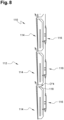
- the system 110 comprises a heating assembly 112 comprising several electric heating modules 114 fixed to a substantially vertical support not shown by means of a plurality of attachment devices 116 which are here all identical to each other from one module to another.
- Each module 114 here presents the configuration of module 70 of the Figure 5 with the exception, however, of the internal deflector 118 which here is positioned by its flat upper part against the flat upper part of the rear cover of the module.
- the air outlet opening(s) O4 of the Figure 5 referenced here O"4 are offset towards the rear of the hood on the figure 8 , set back from the front wall.
- the other details of the construction of the Figure 5 are not included on the figure 8 for the sake of simplicity.
- the inclined upward arrows which are each arranged in the geometric gap formed between two neighboring modules (lower module and upper module) each represent the air flow deflected heat which escapes from the lower module away from the upper module in order to limit, or even avoid, thermally influencing the upper module.
Landscapes
- Engineering & Computer Science (AREA)
- Physics & Mathematics (AREA)
- Thermal Sciences (AREA)
- Chemical & Material Sciences (AREA)
- Combustion & Propulsion (AREA)
- Mechanical Engineering (AREA)
- General Engineering & Computer Science (AREA)
- Cooling Or The Like Of Electrical Apparatus (AREA)
- Air-Conditioning For Vehicles (AREA)
Claims (10)
- System (10), das einen Heizsatz (12) und einen im Wesentlichen vertikalen Halter (14) umfasst, an dem der Heizsatz befestigt ist, wobei der Heizsatz (12) mindestens zwei elektrische Heizmodule (16, 18) umfasst, die an dem vertikalen Halter angeordnet sind, wobei eines der Module, das sogenannte obere Modul (18), höher als das andere Modul, genannt unteres Modul (16), ist, wobei jedes elektrische Heizmodul einen Körper (20, 46, 84, 94) umfasst, der mindestens ein elektrisches Heizelement (22) enthält und außen durch eine Wand begrenzt ist, wobei die Wand einerseits mit einer oder mehreren Lufteintrittsöffnungen versehen ist, die in ihrem unteren Teil eingerichtet sind, und andererseits mit einer oder mehreren Luftaustrittsöffnungen, die in ihrem oberen Teil eingerichtet sind, um einen aufsteigenden Luftstrom in dem Inneren des Körpers, insbesondere über das mindestens eine zu kühlende elektrische Heizelement, zu erzeugen, wobei mindestens ein Teil der Luftaustrittsöffnung(en) jedes Moduls so ausgerichtet ist, dass mindestens ein Teil des aus dem Modul austretenden Luftstroms so umgeleitet wird, dass für das untere (16) und das obere (18) Modul der mindestens eine Teil des durch das mindestens eine elektrische Heizelement (22) erwärmten und aus dem unteren Modul (16) austretenden Luftstroms von dem oberen Modul (18) weg umgelenkt wird, dadurch gekennzeichnet, dass jedes Modul (16, 18) eine zusätzliche Wand (32, 42, 62, 72, 102) aufweist, die vor der Frontwand (26, 48, 82, 98) des Modulkörpers (20, 46, 84, 94) und in einem Abstand von dieser Wand angeordnet ist, um eine vordere Fassade für den Körper (20, 46, 84, 94) zu bilden.
- System (10) nach Anspruch 1, dadurch gekennzeichnet, dass die den Körper (20) jedes Moduls (16, 18) begrenzende Wand eine Rückwand (24) und die der Rückwand (24) gegenüberliegende Frontwand (26) aufweist, wobei die Rückwand (24) dem im Wesentlichen vertikalen Halter zugewandt ist, wobei der mindestens eine Teil der Luftaustrittsöffnung(en), der so ausgerichtet ist, dass er mindestens einen Teil des aus dem Modul austretenden Luftstroms ablenkt, in dem oberen Teil der Frontwand (26) eingerichtet ist.
- System (10) nach Anspruch 1 oder 2, dadurch gekennzeichnet, dass die zusätzliche Wand (72), die die vordere Fassade bildet, in Bezug auf die Frontwand (26) so geneigt ist, dass der Abstand zwischen der zusätzlichen Wand und der Frontwand im oberen Teil des Körpers (20) größer ist als im unteren Teil.
- System (10) nach Anspruch 3, dadurch gekennzeichnet, dass die zusätzliche Wand (72), die die vordere Fassade bildet, in Bezug auf die Frontwand (26) um einen Winkel mit einem Wert zwischen 1 und 45° geneigt ist.
- System (10) nach einem der vorhergehenden Ansprüche, dadurch gekennzeichnet, dass die zusätzliche Wand (32), die die vordere Fassade bildet, in ihrer Dicke über mindestens einen Teil ihrer Oberfläche perforiert ist.
- System (10) nach einem der vorhergehenden Ansprüche, dadurch gekennzeichnet, dass die zusätzliche Wand (32, 62, 72), die die vordere Fassade bildet, Abmessungen hat, die gleich oder größer sind als die der Frontwand (26, 48, 82) .
- System (10) nach einem der vorhergehenden Ansprüche, dadurch gekennzeichnet, dass die Frontwand (98) eine allgemein konkave Form darstellt, die zum Äußeren des Körpers (94) hin ausgerichtet ist, um den mindestens einen Teil des aus dem Modul austretenden Luftstroms, der abgelenkt wird, nach außen zu leiten.
- System (10) nach einem der vorhergehenden Ansprüche, dadurch gekennzeichnet, dass der Körper (94) jedes Moduls einen inneren Deflektor (100) enthält, der so angeordnet ist, dass er den aufsteigenden Luftstrom, der den Bereich des Körpers (94) durchquert, in dem sich das mindestens eine elektrische Heizelement (22) befindet, in Richtung des mindestens einen Teils der Luftaustrittsöffnung(en) (O3) ablenkt, der so ausgerichtet ist, dass er mindestens einen Teil des aus dem Modul austretenden Luftstroms ablenkt, und der als ausgerichteter Luftaustrittsöffnungsteil bezeichnet wird.
- System (10) nach Anspruch 8, dadurch gekennzeichnet, dass der innere Deflektor (100) den aufsteigenden Luftstrom, der durch die Lufteintrittsöffnung(en) in den Körper eintritt, einerseits in einen ersten aufsteigenden Luftstrom, der einen ersten Bereich durchquert, in dem sich das mindestens eine elektrische Heizelement befindet, und andererseits in einen zweiten aufsteigenden Luftstrom, der einen zweiten Bereich des Körpers durchquert, trennt, wobei der innere Deflektor diesen zweiten aufsteigenden Luftstrom in Richtung einer oder mehrerer weiterer Luftaustrittsöffnungen leitet, die in einem oberen Teil der im Wesentlichen horizontalen Wand des Körpers angeordnet und von dem durch den inneren Deflektor ausgerichteten Luftaustrittsöffnungsteil getrennt sind.
- System (10) nach Anspruch 9, dadurch gekennzeichnet, dass der innere Deflektor (100) eine Wärmeschutzfunktion zwischen dem ersten Bereich, in dem sich das mindestens eine elektrische Heizelement (22) befindet, und dem zweiten Bereich des Körpers, der vom zweiten Luftstrom durchströmt wird, hat.
Applications Claiming Priority (1)
| Application Number | Priority Date | Filing Date | Title |
|---|---|---|---|
| FR2101029A FR3119443B1 (fr) | 2021-02-03 | 2021-02-03 | Système à ensemble de modules chauffants |
Publications (2)
| Publication Number | Publication Date |
|---|---|
| EP4040052A1 EP4040052A1 (de) | 2022-08-10 |
| EP4040052B1 true EP4040052B1 (de) | 2025-05-07 |
Family
ID=74759180
Family Applications (1)
| Application Number | Title | Priority Date | Filing Date |
|---|---|---|---|
| EP22154921.5A Active EP4040052B1 (de) | 2021-02-03 | 2022-02-03 | System mit heizmodulsatz |
Country Status (3)
| Country | Link |
|---|---|
| EP (1) | EP4040052B1 (de) |
| FR (1) | FR3119443B1 (de) |
| PL (1) | PL4040052T3 (de) |
Family Cites Families (6)
| Publication number | Priority date | Publication date | Assignee | Title |
|---|---|---|---|---|
| FR2847662B1 (fr) * | 2002-11-25 | 2005-09-30 | Atlantic Industrie Sas | Appareil de chauffage et son utilisation pour simultanement chauffer une piece et secher du linge |
| FR2868518B1 (fr) * | 2004-03-31 | 2006-06-16 | Atlantic Ind Soc Par Actions S | Dispositif de sechage de linge et de chauffage a evacuation d'air chaud par le montant |
| ES2554650B1 (es) | 2014-05-19 | 2016-09-14 | Exploded View, S.L. | Sistema dinámico de calefacción |
| WO2017158580A1 (en) * | 2016-03-18 | 2017-09-21 | James Gerard Tangney | A space temperature controlling apparatus and a space heating apparatus |
| FR3073930B1 (fr) * | 2017-11-21 | 2020-05-15 | Thermor | Systeme de chauffage electrique modulaire |
| FR3082110B1 (fr) * | 2018-06-08 | 2020-11-27 | Atlantic Industrie Sas | Radiateur seche-serviette electrique comprenant un moyen de soufflage configure pour faire circuler de l’air depuis au moins une entree d’air de support vers au moins une sortie d’air d’element d’etendage |
-
2021
- 2021-02-03 FR FR2101029A patent/FR3119443B1/fr active Active
-
2022
- 2022-02-03 EP EP22154921.5A patent/EP4040052B1/de active Active
- 2022-02-03 PL PL22154921.5T patent/PL4040052T3/pl unknown
Also Published As
| Publication number | Publication date |
|---|---|
| FR3119443A1 (fr) | 2022-08-05 |
| FR3119443B1 (fr) | 2023-04-14 |
| EP4040052A1 (de) | 2022-08-10 |
| PL4040052T3 (pl) | 2025-09-08 |
Similar Documents
| Publication | Publication Date | Title |
|---|---|---|
| WO2018037184A1 (fr) | Profile d'accroche permettant le passage d'air et ensemble de plafond comprenant un tel profile | |
| EP4040052B1 (de) | System mit heizmodulsatz | |
| EP0078354A1 (de) | Geräuschdämpfende Einrichtung für Brennkraftmaschinen, speziell bei Maschinen für den innerstädtischen und landwirtschaftlichen Einsatz, und Maschinen mit einer solchen Einrichtung | |
| EP1930662B1 (de) | Brennofen mit einer Durchlassprofilhöhe für einen konstanten Luftstrom | |
| EP3158268B1 (de) | Festbrennstoffofen und zuführungsmodul eines solchen ofens | |
| EP1909035B1 (de) | Ofentür mit Verschlusselement | |
| EP2672191A1 (de) | Kondenswasserbehälter und Luftaufbereitungsgerät, das mit einem solchen Behälter ausgestattet ist | |
| EP1292209B1 (de) | Brotröster mit verstärkten wänden | |
| EP2374385A1 (de) | Infrarot-Kochgerät | |
| WO2012020193A1 (fr) | Ensemble de pompe à chaleur et procédé de montage d'un tel ensemble de pompe à chaleur dans un bâti | |
| FR3055344A1 (fr) | Profile d'accroche permettant le passage d'air et ensemble de plafond comprenant un tel profile | |
| EP1936281B1 (de) | Brennofen, der mindestens einen Verengungsmechanismus für das Durchlassprofil des Luftstroms umfasst | |
| EP1741999B1 (de) | Kühlmöbel mit einem unteren, truhenförmigen Warenraum und einem oberen, schrankförmigen Warenraum | |
| FR2984468A1 (fr) | Emetteur de chauffage electrique a action directe du type a chauffage par convection, agence pour eviter les salissures | |
| FR3075321A1 (fr) | Corps de chauffe thermiquement inertiel et reactif et appareil de chauffage electrique le comprenant | |
| CA3033061C (fr) | Profile d'accroche permettant le passage d'air et ensemble de plafond comprenant un tel profile | |
| EP3214368B1 (de) | Heizanlage für gebäude | |
| EP0421841A1 (de) | Einrichtung zur Luftführung und Anlage, die eine derartige Einrichtung enthält | |
| FR2906872A1 (fr) | Four de cuisson comprenant un dispositif de deflexion d'air. | |
| EP1369073B1 (de) | Verbesserter Brotschlitten für Brotröster | |
| EP1726883A2 (de) | Lüftung einer Ofentür | |
| WO2025008282A1 (fr) | Boîtier et procédé de protection d'un dispositif électronique logé dans le boîtier en présence de liquide sur le boîtier | |
| FR2597957A1 (fr) | Foyer a elements demontables individuellement | |
| EP1319901A1 (de) | Luftbehandlungsanlage | |
| FR2805032A1 (fr) | Dispositif de regulation automatique du debit d'air pour la ventilation d'un local |
Legal Events
| Date | Code | Title | Description |
|---|---|---|---|
| PUAI | Public reference made under article 153(3) epc to a published international application that has entered the european phase |
Free format text: ORIGINAL CODE: 0009012 |
|
| STAA | Information on the status of an ep patent application or granted ep patent |
Free format text: STATUS: THE APPLICATION HAS BEEN PUBLISHED |
|
| AK | Designated contracting states |
Kind code of ref document: A1 Designated state(s): AL AT BE BG CH CY CZ DE DK EE ES FI FR GB GR HR HU IE IS IT LI LT LU LV MC MK MT NL NO PL PT RO RS SE SI SK SM TR |
|
| STAA | Information on the status of an ep patent application or granted ep patent |
Free format text: STATUS: REQUEST FOR EXAMINATION WAS MADE |
|
| 17P | Request for examination filed |
Effective date: 20230207 |
|
| RBV | Designated contracting states (corrected) |
Designated state(s): AL AT BE BG CH CY CZ DE DK EE ES FI FR GB GR HR HU IE IS IT LI LT LU LV MC MK MT NL NO PL PT RO RS SE SI SK SM TR |
|
| P01 | Opt-out of the competence of the unified patent court (upc) registered |
Effective date: 20230530 |
|
| GRAP | Despatch of communication of intention to grant a patent |
Free format text: ORIGINAL CODE: EPIDOSNIGR1 |
|
| STAA | Information on the status of an ep patent application or granted ep patent |
Free format text: STATUS: GRANT OF PATENT IS INTENDED |
|
| INTG | Intention to grant announced |
Effective date: 20241128 |
|
| GRAS | Grant fee paid |
Free format text: ORIGINAL CODE: EPIDOSNIGR3 |
|
| GRAA | (expected) grant |
Free format text: ORIGINAL CODE: 0009210 |
|
| STAA | Information on the status of an ep patent application or granted ep patent |
Free format text: STATUS: THE PATENT HAS BEEN GRANTED |
|
| AK | Designated contracting states |
Kind code of ref document: B1 Designated state(s): AL AT BE BG CH CY CZ DE DK EE ES FI FR GB GR HR HU IE IS IT LI LT LU LV MC MK MT NL NO PL PT RO RS SE SI SK SM TR |
|
| REG | Reference to a national code |
Ref country code: GB Ref legal event code: FG4D Free format text: NOT ENGLISH |
|
| REG | Reference to a national code |
Ref country code: CH Ref legal event code: EP |
|
| REG | Reference to a national code |
Ref country code: DE Ref legal event code: R096 Ref document number: 602022014067 Country of ref document: DE |
|
| REG | Reference to a national code |
Ref country code: IE Ref legal event code: FG4D Free format text: LANGUAGE OF EP DOCUMENT: FRENCH |
|
| REG | Reference to a national code |
Ref country code: NL Ref legal event code: MP Effective date: 20250507 |
|
| PG25 | Lapsed in a contracting state [announced via postgrant information from national office to epo] |
Ref country code: FI Free format text: LAPSE BECAUSE OF FAILURE TO SUBMIT A TRANSLATION OF THE DESCRIPTION OR TO PAY THE FEE WITHIN THE PRESCRIBED TIME-LIMIT Effective date: 20250507 Ref country code: ES Free format text: LAPSE BECAUSE OF FAILURE TO SUBMIT A TRANSLATION OF THE DESCRIPTION OR TO PAY THE FEE WITHIN THE PRESCRIBED TIME-LIMIT Effective date: 20250507 Ref country code: PT Free format text: LAPSE BECAUSE OF FAILURE TO SUBMIT A TRANSLATION OF THE DESCRIPTION OR TO PAY THE FEE WITHIN THE PRESCRIBED TIME-LIMIT Effective date: 20250908 |
|
| REG | Reference to a national code |
Ref country code: LT Ref legal event code: MG9D |
|
| PG25 | Lapsed in a contracting state [announced via postgrant information from national office to epo] |
Ref country code: GR Free format text: LAPSE BECAUSE OF FAILURE TO SUBMIT A TRANSLATION OF THE DESCRIPTION OR TO PAY THE FEE WITHIN THE PRESCRIBED TIME-LIMIT Effective date: 20250808 Ref country code: NO Free format text: LAPSE BECAUSE OF FAILURE TO SUBMIT A TRANSLATION OF THE DESCRIPTION OR TO PAY THE FEE WITHIN THE PRESCRIBED TIME-LIMIT Effective date: 20250807 |
|
| PG25 | Lapsed in a contracting state [announced via postgrant information from national office to epo] |
Ref country code: NL Free format text: LAPSE BECAUSE OF FAILURE TO SUBMIT A TRANSLATION OF THE DESCRIPTION OR TO PAY THE FEE WITHIN THE PRESCRIBED TIME-LIMIT Effective date: 20250507 |
|
| REG | Reference to a national code |
Ref country code: AT Ref legal event code: MK05 Ref document number: 1792834 Country of ref document: AT Kind code of ref document: T Effective date: 20250507 |
|
| PG25 | Lapsed in a contracting state [announced via postgrant information from national office to epo] |
Ref country code: BG Free format text: LAPSE BECAUSE OF FAILURE TO SUBMIT A TRANSLATION OF THE DESCRIPTION OR TO PAY THE FEE WITHIN THE PRESCRIBED TIME-LIMIT Effective date: 20250507 |
|
| PG25 | Lapsed in a contracting state [announced via postgrant information from national office to epo] |
Ref country code: HR Free format text: LAPSE BECAUSE OF FAILURE TO SUBMIT A TRANSLATION OF THE DESCRIPTION OR TO PAY THE FEE WITHIN THE PRESCRIBED TIME-LIMIT Effective date: 20250507 |
|
| PG25 | Lapsed in a contracting state [announced via postgrant information from national office to epo] |
Ref country code: AT Free format text: LAPSE BECAUSE OF FAILURE TO SUBMIT A TRANSLATION OF THE DESCRIPTION OR TO PAY THE FEE WITHIN THE PRESCRIBED TIME-LIMIT Effective date: 20250507 |
|
| PG25 | Lapsed in a contracting state [announced via postgrant information from national office to epo] |
Ref country code: RS Free format text: LAPSE BECAUSE OF FAILURE TO SUBMIT A TRANSLATION OF THE DESCRIPTION OR TO PAY THE FEE WITHIN THE PRESCRIBED TIME-LIMIT Effective date: 20250807 |
|
| PG25 | Lapsed in a contracting state [announced via postgrant information from national office to epo] |
Ref country code: IS Free format text: LAPSE BECAUSE OF FAILURE TO SUBMIT A TRANSLATION OF THE DESCRIPTION OR TO PAY THE FEE WITHIN THE PRESCRIBED TIME-LIMIT Effective date: 20250907 |
|
| PG25 | Lapsed in a contracting state [announced via postgrant information from national office to epo] |
Ref country code: LV Free format text: LAPSE BECAUSE OF FAILURE TO SUBMIT A TRANSLATION OF THE DESCRIPTION OR TO PAY THE FEE WITHIN THE PRESCRIBED TIME-LIMIT Effective date: 20250507 |
|
| PG25 | Lapsed in a contracting state [announced via postgrant information from national office to epo] |
Ref country code: DK Free format text: LAPSE BECAUSE OF FAILURE TO SUBMIT A TRANSLATION OF THE DESCRIPTION OR TO PAY THE FEE WITHIN THE PRESCRIBED TIME-LIMIT Effective date: 20250507 Ref country code: SM Free format text: LAPSE BECAUSE OF FAILURE TO SUBMIT A TRANSLATION OF THE DESCRIPTION OR TO PAY THE FEE WITHIN THE PRESCRIBED TIME-LIMIT Effective date: 20250507 |
|
| PG25 | Lapsed in a contracting state [announced via postgrant information from national office to epo] |
Ref country code: CZ Free format text: LAPSE BECAUSE OF FAILURE TO SUBMIT A TRANSLATION OF THE DESCRIPTION OR TO PAY THE FEE WITHIN THE PRESCRIBED TIME-LIMIT Effective date: 20250507 |
|
| PG25 | Lapsed in a contracting state [announced via postgrant information from national office to epo] |
Ref country code: EE Free format text: LAPSE BECAUSE OF FAILURE TO SUBMIT A TRANSLATION OF THE DESCRIPTION OR TO PAY THE FEE WITHIN THE PRESCRIBED TIME-LIMIT Effective date: 20250507 |
|
| PG25 | Lapsed in a contracting state [announced via postgrant information from national office to epo] |
Ref country code: SK Free format text: LAPSE BECAUSE OF FAILURE TO SUBMIT A TRANSLATION OF THE DESCRIPTION OR TO PAY THE FEE WITHIN THE PRESCRIBED TIME-LIMIT Effective date: 20250507 |
|
| PG25 | Lapsed in a contracting state [announced via postgrant information from national office to epo] |
Ref country code: IT Free format text: LAPSE BECAUSE OF FAILURE TO SUBMIT A TRANSLATION OF THE DESCRIPTION OR TO PAY THE FEE WITHIN THE PRESCRIBED TIME-LIMIT Effective date: 20250507 |
|
| REG | Reference to a national code |
Ref country code: DE Ref legal event code: R097 Ref document number: 602022014067 Country of ref document: DE |
|
| PLBE | No opposition filed within time limit |
Free format text: ORIGINAL CODE: 0009261 |
|
| STAA | Information on the status of an ep patent application or granted ep patent |
Free format text: STATUS: NO OPPOSITION FILED WITHIN TIME LIMIT |
|
| REG | Reference to a national code |
Ref country code: CH Ref legal event code: L10 Free format text: ST27 STATUS EVENT CODE: U-0-0-L10-L00 (AS PROVIDED BY THE NATIONAL OFFICE) Effective date: 20260318 |
|
| 26N | No opposition filed |
Effective date: 20260210 |
|
| PGFP | Annual fee paid to national office [announced via postgrant information from national office to epo] |
Ref country code: BE Payment date: 20260218 Year of fee payment: 5 |
|
| PGFP | Annual fee paid to national office [announced via postgrant information from national office to epo] |
Ref country code: FR Payment date: 20260219 Year of fee payment: 5 |