EP4040068A1 - Intelligente elektrische heizvorrichtung - Google Patents
Intelligente elektrische heizvorrichtung Download PDFInfo
- Publication number
- EP4040068A1 EP4040068A1 EP21180844.9A EP21180844A EP4040068A1 EP 4040068 A1 EP4040068 A1 EP 4040068A1 EP 21180844 A EP21180844 A EP 21180844A EP 4040068 A1 EP4040068 A1 EP 4040068A1
- Authority
- EP
- European Patent Office
- Prior art keywords
- unit
- temperature
- water
- heating
- electric heating
- Prior art date
- Legal status (The legal status is an assumption and is not a legal conclusion. Google has not performed a legal analysis and makes no representation as to the accuracy of the status listed.)
- Granted
Links
Images


Classifications
-
- F—MECHANICAL ENGINEERING; LIGHTING; HEATING; WEAPONS; BLASTING
- F24—HEATING; RANGES; VENTILATING
- F24H—FLUID HEATERS, e.g. WATER OR AIR HEATERS, HAVING HEAT-GENERATING MEANS, e.g. HEAT PUMPS, IN GENERAL
- F24H9/00—Details
- F24H9/20—Arrangement or mounting of control or safety devices
- F24H9/2007—Arrangement or mounting of control or safety devices for water heaters
- F24H9/2014—Arrangement or mounting of control or safety devices for water heaters using electrical energy supply
- F24H9/2021—Storage heaters
-
- F—MECHANICAL ENGINEERING; LIGHTING; HEATING; WEAPONS; BLASTING
- F24—HEATING; RANGES; VENTILATING
- F24H—FLUID HEATERS, e.g. WATER OR AIR HEATERS, HAVING HEAT-GENERATING MEANS, e.g. HEAT PUMPS, IN GENERAL
- F24H1/00—Water heaters, e.g. boilers, continuous-flow heaters or water-storage heaters
- F24H1/10—Continuous-flow heaters, i.e. heaters in which heat is generated only while the water is flowing, e.g. with direct contact of the water with the heating medium
- F24H1/12—Continuous-flow heaters, i.e. heaters in which heat is generated only while the water is flowing, e.g. with direct contact of the water with the heating medium in which the water is kept separate from the heating medium
- F24H1/121—Continuous-flow heaters, i.e. heaters in which heat is generated only while the water is flowing, e.g. with direct contact of the water with the heating medium in which the water is kept separate from the heating medium using electric energy supply
- F24H1/122—Continuous-flow heaters, i.e. heaters in which heat is generated only while the water is flowing, e.g. with direct contact of the water with the heating medium in which the water is kept separate from the heating medium using electric energy supply combined with storage tank
-
- F—MECHANICAL ENGINEERING; LIGHTING; HEATING; WEAPONS; BLASTING
- F24—HEATING; RANGES; VENTILATING
- F24H—FLUID HEATERS, e.g. WATER OR AIR HEATERS, HAVING HEAT-GENERATING MEANS, e.g. HEAT PUMPS, IN GENERAL
- F24H1/00—Water heaters, e.g. boilers, continuous-flow heaters or water-storage heaters
- F24H1/18—Water-storage heaters
- F24H1/20—Water-storage heaters with immersed heating elements, e.g. electric elements or furnace tubes
- F24H1/201—Water-storage heaters with immersed heating elements, e.g. electric elements or furnace tubes using electric energy supply
-
- F—MECHANICAL ENGINEERING; LIGHTING; HEATING; WEAPONS; BLASTING
- F24—HEATING; RANGES; VENTILATING
- F24H—FLUID HEATERS, e.g. WATER OR AIR HEATERS, HAVING HEAT-GENERATING MEANS, e.g. HEAT PUMPS, IN GENERAL
- F24H1/00—Water heaters, e.g. boilers, continuous-flow heaters or water-storage heaters
- F24H1/18—Water-storage heaters
- F24H1/20—Water-storage heaters with immersed heating elements, e.g. electric elements or furnace tubes
- F24H1/201—Water-storage heaters with immersed heating elements, e.g. electric elements or furnace tubes using electric energy supply
- F24H1/202—Water-storage heaters with immersed heating elements, e.g. electric elements or furnace tubes using electric energy supply with resistances
-
- F—MECHANICAL ENGINEERING; LIGHTING; HEATING; WEAPONS; BLASTING
- F24—HEATING; RANGES; VENTILATING
- F24H—FLUID HEATERS, e.g. WATER OR AIR HEATERS, HAVING HEAT-GENERATING MEANS, e.g. HEAT PUMPS, IN GENERAL
- F24H9/00—Details
- F24H9/12—Arrangements for connecting heaters to circulation pipes
- F24H9/13—Arrangements for connecting heaters to circulation pipes for water heaters
- F24H9/133—Storage heaters
- F24H9/136—Arrangement of inlet valves used therewith
-
- F—MECHANICAL ENGINEERING; LIGHTING; HEATING; WEAPONS; BLASTING
- F24—HEATING; RANGES; VENTILATING
- F24H—FLUID HEATERS, e.g. WATER OR AIR HEATERS, HAVING HEAT-GENERATING MEANS, e.g. HEAT PUMPS, IN GENERAL
- F24H9/00—Details
- F24H9/20—Arrangement or mounting of control or safety devices
- F24H9/2007—Arrangement or mounting of control or safety devices for water heaters
- F24H9/2014—Arrangement or mounting of control or safety devices for water heaters using electrical energy supply
- F24H9/2028—Continuous-flow heaters
-
- H—ELECTRICITY
- H05—ELECTRIC TECHNIQUES NOT OTHERWISE PROVIDED FOR
- H05B—ELECTRIC HEATING; ELECTRIC LIGHT SOURCES NOT OTHERWISE PROVIDED FOR; CIRCUIT ARRANGEMENTS FOR ELECTRIC LIGHT SOURCES, IN GENERAL
- H05B1/00—Details of electric heating devices
- H05B1/02—Automatic switching arrangements specially adapted to apparatus ; Control of heating devices
- H05B1/0227—Applications
- H05B1/0297—Heating of fluids for non specified applications
Definitions
- the present invention relates to a smart electric heating device.
- Electric heating devices such as water heaters
- thermal storage water heaters as disclosed in Taiwan Utility Model Publication No. M281147 titled “structural improvement of storage-type electric water heater”
- instantaneous water heaters as disclosed in Taiwan Patent Publication No. 1471510 titled "electric heating device”.
- a thermal storage water heater or an instantaneous water heater is selectively installed.
- the thermal storage water heater consumes excess energy and requires a long wait.
- the power of the instantaneous water heater is limited by the wiring of a building, and the water temperature to be increased by heating is limited. Especially in cold areas, it is difficult to take a hot bath through the heating of the instantaneous water heater.
- the primary object of the present invention is to provide a smart electric heating device, comprising: a storage unit, stored with water; a first heating unit, disposed in the storage unit; a liquid pipe, adjacent to the storage unit, the liquid pipe having an inlet communicating with the storage unit and an outlet opposite to the inlet; a second heating unit, adjacent to the storage unit and corresponding to the liquid pipe, the second heating unit being configured to heat water in the liquid pipe with a maximum increased temperature; a control unit, being in signal connection with the first heating unit and the second heating unit; and a first temperature sensing unit, being in signal connection with the control unit, the first temperature sensing unit being disposed outside the storage unit, the first temperature sensing unit being configured to obtain an ambient temperature outside the storage unit; wherein after the first temperature sensing unit obtains the ambient temperature, the control unit compares the ambient temperature with the maximum increased temperature and a set temperature; wherein when a difference value between the set temperature and the ambient temperature is greater than the maximum increased temperature, the control unit controls the first heating unit to actuate for heating
- the smart electric heating device further comprises a flow sensing unit adjacent to the inlet and corresponding to the liquid pipe.
- the flow sensing unit is in signal connection with the control unit.
- the control unit controls the first heating unit not to actuate and the second heating unit to actuate.
- the smart electric heating device further comprises a plurality of heating sections between the inlet and the outlet.
- the second heating unit is a plurality of electric heating rods accommodated in the respective heating sections.
- the control unit includes a plurality of control members electrically connected to the respective electric heating rods.
- the smart electric heating device further comprises a second temperature sensing unit and a flow sensing unit adjacent to the inlet and corresponding to the liquid pipe.
- the second temperature sensing unit and the flow sensing unit are in signal connection with the control unit.
- the control unit controls a heating power of each of the electric heating rods through the respective control members according to a difference value between the set temperature and the influent water temperature as well as the flow rate change.
- control members are thyristors.
- the heating power of each of the electric heating rods is between 0% and 100% of a maximum heating power.
- the heating power of all the electric heating rods is 100% of the maximum heating power, it corresponds to the maximum increased temperature.
- the smart electric heating device further comprises a third temperature sensing unit disposed in the storage unit and configured to obtain a storage water temperature in the storage unit.
- the third temperature sensing unit is in signal connection with the control unit.
- the control unit controls the first heating unit not to actuate.
- the smart electric heating device further comprises a water level detection unit disposed in the storage unit and a water replenishment unit communicating with the storage unit.
- the water level detection unit and the water replenishment unit are in signal connection with the control unit.
- the control unit controls the water replenishment unit to replenish water to the storage unit.
- the liquid pipe is disposed under the storage unit, and the inlet is lower than the storage unit.
- a sum of the set temperature and the ambient temperature is a fixed value.
- the first heating unit is an electric heating rod
- the control unit includes a relay electrically connected to the electric heating rod.
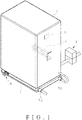
- the present invention discloses a smart electric heating device, comprising a control unit 1, a storage unit 2, a first heating unit, a first temperature sensing unit 4, a water level detection unit 5, and a water replenishment unit 6.
- a control box 7 is disposed below the storage unit 2.
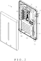
- the control box 7 has a liquid pipe 71, a second heating unit, a flow sensing unit 73, and a second temperature sensing unit 74.
- the control box 7 is provided with a power terminal 75 connected to an external power source (not shown).
- a protection unit 76 is electrically connected to the power terminal 75 to cut off power when the control box 7 is abnormal.
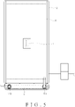
- the storage unit 2 is stored with a use water A (as shown in FIG. 5 ), such as a water tank of a general water heater.
- the storage unit 2 has a third temperature sensing unit 8 to obtain a storage water temperature of the use water A in the storage unit 2.
- the liquid pipe 71 has an inlet 711 communicating with the storage unit 2 and an outlet 712 opposite to the inlet 711.
- the inlet 711 is lower than the storage unit 2.
- the outlet 712 is in communication with a water use apparatus, such as a faucet.
- a plurality of heating sections 713 are provided between the inlet 711 and the outlet 712. The heating sections 713 are parallel to each other.
- the first heating unit is a first electric heating rod 3, and is disposed in the storage unit 2.
- the second heating unit is a plurality of second electric heating rods 72, and is disposed under the storage unit 2.
- the second electric heating rods 72 are accommodated in the respective heating sections 713.
- the control unit 1 is in signal connection with the first electric heating rod 3, the second electric heating rods 72, the flow sensing unit 73, the first temperature sensing unit 4, the second temperature sensing unit 74, the water level detection Unit 5, the water replenishment unit 6, and the third temperature sensing unit 8.
- the control unit 1 includes a relay 11 electrically connected to the first electric heating rod 3 and a plurality of thyristors 12 electrically connected to the respective second electric heating rods 72.
- the second electric heating rods 72 are configured to heat the use water A in the liquid pipe 71.
- the heating power of each second electric heating rod 72 is between 0% and 100% of a maximum heating power. When the heating power of all the second electric heating rods 72 is 100% of the maximum heating power, it corresponds to a maximum increased temperature of the use water A, such as 20 degrees Celsius.
- the first temperature sensing unit 4 is disposed below the outside of the storage unit 2.
- the flow sensing unit 73 and the second temperature sensing unit 74 are disposed between the inlet 711 and the heating sections 713 and correspond to the liquid pipe 71.
- the flow sensing unit 73 is closer to the inlet 711 than the second temperature sensing unit 74.
- the water level detection unit 5 is disposed in the storage unit 2.
- the water replenishment unit 6 is in communication with the storage unit 2, such as a water solenoid valve.
- the first temperature sensing unit 4 obtains an ambient temperature outside the storage unit 2 and sends it to the control unit 1.
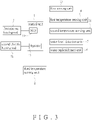
- the control unit 1 compares the ambient temperature with the maximum increased temperature and a set temperature. If the difference value between the set temperature and the ambient temperature is greater than the maximum increased temperature, the control unit 1 controls the first electric heating rod 3 to actuate.
- the sum of the set temperature and the ambient temperature may be a fixed value, so that the control unit 1 can automatically adjust the set temperature according to different seasons.
- the control unit 1 controls the first electric heating rod 3 to actuate for heating the use water in the storage unit 2.
- the third temperature sensing unit 8 can continuously obtain the storage water temperature.
- the control unit 1 controls the first electric heating rod 3 not to actuate. Even if the user has not turned on the water use apparatus, the control unit 1 still appropriately controls the first electric heating rod 3 not to actuate. If the storage water temperature of the use water A in the storage unit 2 drops again, the control unit 1 can control the first electric heating rod 3 to actuate again, but this scenario is not shown in the figures.
- the control unit 1 controls the first electric heating rod 3 not to actuate.
- FIGS. 5-7 Please refer to FIGS. 5-7 in cooperation with FIG. 3 .
- the use water A in the storage unit 2 flows into the liquid pipe 71 through the inlet 711.
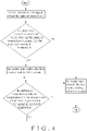
- the control unit 1 controls the first electric heating rod 3 not to actuate when the flow sensing unit 73 obtains that a flow rate change of the water in the liquid pipe 71 is not zero.
- the second temperature sensing unit 74 obtains an influent water temperature of the use water A and sends it to the control unit 1. Then, the control unit 1 controls the actuation and heating power of each of the second electric heating rods 72 through the respective thyristors 12 according to the difference value between the set temperature and the influent water temperature as well as the flow rate change, thereby reducing unnecessary energy consumption. Besides, the use water A can be accurately heated to the set temperature.
- the second electric heating rods 72 are not actuated. Then, when the use water A continues to flow to the outlet 712, an effluent water temperature will reach the set temperature.
- FIGS. 8-10 in cooperation with FIG. 3 .
- the control unit 1 controls the water replenishment unit 6 to replenish the use water A to the storage unit 2.
- the smart electric heating device of the present invention decides in advance whether to preheat the use water A in the storage unit 2 according to the relatively stable ambient temperature, and adjusts the heating power of the second electric heating rods 72 to ensure that the effluent water temperature reaches the set temperature. This allows users to use hot water of sufficient temperature better in different seasons and regions.
Landscapes
- Engineering & Computer Science (AREA)
- General Engineering & Computer Science (AREA)
- Chemical & Material Sciences (AREA)
- Thermal Sciences (AREA)
- Combustion & Propulsion (AREA)
- Mechanical Engineering (AREA)
- Physics & Mathematics (AREA)
- Heat-Pump Type And Storage Water Heaters (AREA)
- Instantaneous Water Boilers, Portable Hot-Water Supply Apparatuses, And Control Of Portable Hot-Water Supply Apparatuses (AREA)
- Yarns And Mechanical Finishing Of Yarns Or Ropes (AREA)
- Control Of High-Frequency Heating Circuits (AREA)
- Mounting, Exchange, And Manufacturing Of Dies (AREA)
- Control Of Resistance Heating (AREA)
Applications Claiming Priority (1)
| Application Number | Priority Date | Filing Date | Title |
|---|---|---|---|
| TW110104768A TWI767557B (zh) | 2021-02-08 | 2021-02-08 | 智能電加熱裝置 |
Publications (3)
| Publication Number | Publication Date |
|---|---|
| EP4040068A1 true EP4040068A1 (de) | 2022-08-10 |
| EP4040068C0 EP4040068C0 (de) | 2025-11-05 |
| EP4040068B1 EP4040068B1 (de) | 2025-11-05 |
Family
ID=76553597
Family Applications (1)
| Application Number | Title | Priority Date | Filing Date |
|---|---|---|---|
| EP21180844.9A Active EP4040068B1 (de) | 2021-02-08 | 2021-06-22 | Intelligente elektrische heizvorrichtung |
Country Status (4)
| Country | Link |
|---|---|
| US (1) | US11686503B2 (de) |
| EP (1) | EP4040068B1 (de) |
| JP (1) | JP7174911B2 (de) |
| TW (1) | TWI767557B (de) |
Families Citing this family (1)
| Publication number | Priority date | Publication date | Assignee | Title |
|---|---|---|---|---|
| USD1058780S1 (en) * | 2022-05-26 | 2025-01-21 | Rinnai Corporation | Water heater |
Citations (6)
| Publication number | Priority date | Publication date | Assignee | Title |
|---|---|---|---|---|
| WO1983001993A1 (en) * | 1981-12-03 | 1983-06-09 | Vaillant Joh Gmbh & Co | Electric water heater |
| EP1548376A1 (de) * | 2003-12-22 | 2005-06-29 | THERMOWATT S.p.A. | Nachheizeinrichtung für elektrischen Heizwasserspeicher |
| US20100195991A1 (en) * | 2009-02-03 | 2010-08-05 | Sridhar Deivasigamani | Apparatus and control method for a hybrid tankless water heater |
| US20130308930A1 (en) * | 2012-05-16 | 2013-11-21 | Yu-Chen Lin | Electric heating device |
| WO2014101659A1 (zh) * | 2012-12-25 | 2014-07-03 | Chen Jianliang | 双加热系统的开水器 |
| CN111271873A (zh) * | 2018-12-05 | 2020-06-12 | 长春以书会友文化传媒有限公司 | 一种大出水量的组合式电热水器 |
Family Cites Families (13)
| Publication number | Priority date | Publication date | Assignee | Title |
|---|---|---|---|---|
| US4638944A (en) * | 1986-04-21 | 1987-01-27 | Kujawa Stephen M | Compact high volume point of use instantaneous water heating system |
| JP2003050051A (ja) * | 2001-08-06 | 2003-02-21 | Hitachi Ltd | ヒートポンプ式給湯装置 |
| JP2007127318A (ja) * | 2005-11-02 | 2007-05-24 | Nippon Thermostat Co Ltd | 給湯装置 |
| US8366014B2 (en) * | 2007-02-21 | 2013-02-05 | A. O. Smith Enterprises Ltd. | Tank-tankless water heater |
| US20080216770A1 (en) * | 2007-03-05 | 2008-09-11 | Rinnai America Corporation, A Corporation Of Georgia | Water heating system |
| US20120060827A1 (en) * | 2011-03-07 | 2012-03-15 | General Electric Company | Control for a tankless water heater used with a solar water heating system |
| US8768154B2 (en) * | 2011-06-21 | 2014-07-01 | Daichi L Nakagawa | Fixed and selectively fixed bypass pumpless instantaneous / storage water heater system |
| JP6052675B2 (ja) * | 2013-04-25 | 2016-12-27 | パナソニックIpマネジメント株式会社 | ヒートポンプシステム制御装置、ヒートポンプシステム、および、ヒートポンプシステム制御方法 |
| CN105180454B (zh) * | 2015-10-10 | 2018-11-06 | 珠海格力电器股份有限公司 | 热水器及其控制方法和装置 |
| US10605486B2 (en) * | 2017-12-04 | 2020-03-31 | Rheem Manufacturing Company | Tank-based and tankless water heater systems |
| CN111964272A (zh) * | 2020-07-14 | 2020-11-20 | 华帝股份有限公司 | 一种电热水器的控制方法及电热水器 |
| CN111912122A (zh) * | 2020-08-11 | 2020-11-10 | 华帝股份有限公司 | 一种电热水器的控制方法及电热水器 |
| TWM620857U (zh) * | 2021-02-08 | 2021-12-11 | 阿斯嘉能源科技有限公司 | 智能電加熱裝置 |
-
2021
- 2021-02-08 TW TW110104768A patent/TWI767557B/zh active
- 2021-05-25 US US17/329,550 patent/US11686503B2/en active Active
- 2021-06-22 EP EP21180844.9A patent/EP4040068B1/de active Active
- 2021-07-05 JP JP2021111467A patent/JP7174911B2/ja active Active
Patent Citations (7)
| Publication number | Priority date | Publication date | Assignee | Title |
|---|---|---|---|---|
| WO1983001993A1 (en) * | 1981-12-03 | 1983-06-09 | Vaillant Joh Gmbh & Co | Electric water heater |
| EP1548376A1 (de) * | 2003-12-22 | 2005-06-29 | THERMOWATT S.p.A. | Nachheizeinrichtung für elektrischen Heizwasserspeicher |
| US20100195991A1 (en) * | 2009-02-03 | 2010-08-05 | Sridhar Deivasigamani | Apparatus and control method for a hybrid tankless water heater |
| US20130308930A1 (en) * | 2012-05-16 | 2013-11-21 | Yu-Chen Lin | Electric heating device |
| TWI471510B (zh) | 2012-05-16 | 2015-02-01 | Yu Chen Lin | 電加熱裝置 |
| WO2014101659A1 (zh) * | 2012-12-25 | 2014-07-03 | Chen Jianliang | 双加热系统的开水器 |
| CN111271873A (zh) * | 2018-12-05 | 2020-06-12 | 长春以书会友文化传媒有限公司 | 一种大出水量的组合式电热水器 |
Also Published As
| Publication number | Publication date |
|---|---|
| US20220252302A1 (en) | 2022-08-11 |
| JP2022121358A (ja) | 2022-08-19 |
| JP7174911B2 (ja) | 2022-11-18 |
| US11686503B2 (en) | 2023-06-27 |
| EP4040068C0 (de) | 2025-11-05 |
| TWI767557B (zh) | 2022-06-11 |
| TW202232036A (zh) | 2022-08-16 |
| EP4040068B1 (de) | 2025-11-05 |
Similar Documents
| Publication | Publication Date | Title |
|---|---|---|
| US7945146B2 (en) | Tankless hot water heater with power modulation | |
| CN110998194B (zh) | 再循环流体加热系统 | |
| US20230151974A1 (en) | Integrated recirculation pump for non-condensing water heater | |
| CN101663543B (zh) | 改进的用于加热流体的系统和方法 | |
| CN110440443A (zh) | 一种热水器系统 | |
| JP4192875B2 (ja) | ヒートポンプ式給湯装置 | |
| US11867429B2 (en) | Tankless water heater with integrated variable speed pump | |
| CN111503903A (zh) | 一种热水器精准恒温控制系统以及控制方法 | |
| EP4040068A1 (de) | Intelligente elektrische heizvorrichtung | |
| CN107202425A (zh) | 热水器末端调节装置及具有其的热水器组件 | |
| JP7251507B2 (ja) | 貯湯式給湯装置 | |
| NL2022590B1 (en) | Electric boiler, central heating system comprising an electric boiler, tap water heating system comprising an electric boiler and method for operating the same | |
| TWM620857U (zh) | 智能電加熱裝置 | |
| JP2000130851A (ja) | 電気温水器及びその加熱制御方法 | |
| CN117847783A (zh) | 回水装置、热水系统、热水系统的控制方法以及热水器 | |
| JP4379385B2 (ja) | 給湯装置 | |
| CN115235115A (zh) | 智能电加热装置 | |
| CN206989445U (zh) | 管线热水机 | |
| EP2450635A1 (de) | Solarheizungssystem | |
| CN111121271A (zh) | 一种基于热水恒温的室内混合电力控制系统 | |
| JP2005315523A (ja) | 給湯装置 | |
| CN108253631A (zh) | 一种循环热泵热水器控制装置及方法 | |
| KR100469474B1 (ko) | 심야 전기를 이용한 전기보일러 | |
| US20120002955A1 (en) | Temperature control and power management control system for hydraulic heating systems | |
| AU2019226145A1 (en) | A water heating system |
Legal Events
| Date | Code | Title | Description |
|---|---|---|---|
| PUAI | Public reference made under article 153(3) epc to a published international application that has entered the european phase |
Free format text: ORIGINAL CODE: 0009012 |
|
| STAA | Information on the status of an ep patent application or granted ep patent |
Free format text: STATUS: THE APPLICATION HAS BEEN PUBLISHED |
|
| AK | Designated contracting states |
Kind code of ref document: A1 Designated state(s): AL AT BE BG CH CY CZ DE DK EE ES FI FR GB GR HR HU IE IS IT LI LT LU LV MC MK MT NL NO PL PT RO RS SE SI SK SM TR |
|
| STAA | Information on the status of an ep patent application or granted ep patent |
Free format text: STATUS: REQUEST FOR EXAMINATION WAS MADE |
|
| 17P | Request for examination filed |
Effective date: 20230209 |
|
| RBV | Designated contracting states (corrected) |
Designated state(s): AL AT BE BG CH CY CZ DE DK EE ES FI FR GB GR HR HU IE IS IT LI LT LU LV MC MK MT NL NO PL PT RO RS SE SI SK SM TR |
|
| GRAP | Despatch of communication of intention to grant a patent |
Free format text: ORIGINAL CODE: EPIDOSNIGR1 |
|
| STAA | Information on the status of an ep patent application or granted ep patent |
Free format text: STATUS: GRANT OF PATENT IS INTENDED |
|
| INTG | Intention to grant announced |
Effective date: 20250602 |
|
| GRAS | Grant fee paid |
Free format text: ORIGINAL CODE: EPIDOSNIGR3 |
|
| GRAA | (expected) grant |
Free format text: ORIGINAL CODE: 0009210 |
|
| STAA | Information on the status of an ep patent application or granted ep patent |
Free format text: STATUS: THE PATENT HAS BEEN GRANTED |
|
| AK | Designated contracting states |
Kind code of ref document: B1 Designated state(s): AL AT BE BG CH CY CZ DE DK EE ES FI FR GB GR HR HU IE IS IT LI LT LU LV MC MK MT NL NO PL PT RO RS SE SI SK SM TR |
|
| REG | Reference to a national code |
Ref country code: CH Ref legal event code: F10 Free format text: ST27 STATUS EVENT CODE: U-0-0-F10-F00 (AS PROVIDED BY THE NATIONAL OFFICE) Effective date: 20251105 Ref country code: GB Ref legal event code: FG4D |
|
| REG | Reference to a national code |
Ref country code: DE Ref legal event code: R096 Ref document number: 602021041648 Country of ref document: DE |
|
| REG | Reference to a national code |
Ref country code: IE Ref legal event code: FG4D |
|
| U01 | Request for unitary effect filed |
Effective date: 20251202 |
|
| U07 | Unitary effect registered |
Designated state(s): AT BE BG DE DK EE FI FR IT LT LU LV MT NL PT RO SE SI Effective date: 20260112 |
|
| PG25 | Lapsed in a contracting state [announced via postgrant information from national office to epo] |
Ref country code: ES Free format text: LAPSE BECAUSE OF FAILURE TO SUBMIT A TRANSLATION OF THE DESCRIPTION OR TO PAY THE FEE WITHIN THE PRESCRIBED TIME-LIMIT Effective date: 20251105 |
|
| PG25 | Lapsed in a contracting state [announced via postgrant information from national office to epo] |
Ref country code: NO Free format text: LAPSE BECAUSE OF FAILURE TO SUBMIT A TRANSLATION OF THE DESCRIPTION OR TO PAY THE FEE WITHIN THE PRESCRIBED TIME-LIMIT Effective date: 20260205 |
|
| PG25 | Lapsed in a contracting state [announced via postgrant information from national office to epo] |
Ref country code: HR Free format text: LAPSE BECAUSE OF FAILURE TO SUBMIT A TRANSLATION OF THE DESCRIPTION OR TO PAY THE FEE WITHIN THE PRESCRIBED TIME-LIMIT Effective date: 20251105 |
|
| PG25 | Lapsed in a contracting state [announced via postgrant information from national office to epo] |
Ref country code: RS Free format text: LAPSE BECAUSE OF FAILURE TO SUBMIT A TRANSLATION OF THE DESCRIPTION OR TO PAY THE FEE WITHIN THE PRESCRIBED TIME-LIMIT Effective date: 20260205 |
|
| PG25 | Lapsed in a contracting state [announced via postgrant information from national office to epo] |
Ref country code: IS Free format text: LAPSE BECAUSE OF FAILURE TO SUBMIT A TRANSLATION OF THE DESCRIPTION OR TO PAY THE FEE WITHIN THE PRESCRIBED TIME-LIMIT Effective date: 20260305 |
|
| PG25 | Lapsed in a contracting state [announced via postgrant information from national office to epo] |
Ref country code: PL Free format text: LAPSE BECAUSE OF FAILURE TO SUBMIT A TRANSLATION OF THE DESCRIPTION OR TO PAY THE FEE WITHIN THE PRESCRIBED TIME-LIMIT Effective date: 20251105 |