EP4040076B1 - Kältekreislaufvorrichtung und vierwegeventil - Google Patents
Kältekreislaufvorrichtung und vierwegeventil Download PDFInfo
- Publication number
- EP4040076B1 EP4040076B1 EP20873293.3A EP20873293A EP4040076B1 EP 4040076 B1 EP4040076 B1 EP 4040076B1 EP 20873293 A EP20873293 A EP 20873293A EP 4040076 B1 EP4040076 B1 EP 4040076B1
- Authority
- EP
- European Patent Office
- Prior art keywords
- port
- connection state
- valve
- refrigerant
- refrigeration cycle
- Prior art date
- Legal status (The legal status is an assumption and is not a legal conclusion. Google has not performed a legal analysis and makes no representation as to the accuracy of the status listed.)
- Active
Links
Images


Classifications
-
- F—MECHANICAL ENGINEERING; LIGHTING; HEATING; WEAPONS; BLASTING
- F25—REFRIGERATION OR COOLING; COMBINED HEATING AND REFRIGERATION SYSTEMS; HEAT PUMP SYSTEMS; MANUFACTURE OR STORAGE OF ICE; LIQUEFACTION SOLIDIFICATION OF GASES
- F25B—REFRIGERATION MACHINES, PLANTS OR SYSTEMS; COMBINED HEATING AND REFRIGERATION SYSTEMS; HEAT PUMP SYSTEMS
- F25B41/00—Fluid-circulation arrangements
- F25B41/20—Disposition of valves, e.g. of on-off valves or flow control valves
- F25B41/26—Disposition of valves, e.g. of on-off valves or flow control valves of fluid flow reversing valves
-
- F—MECHANICAL ENGINEERING; LIGHTING; HEATING; WEAPONS; BLASTING
- F25—REFRIGERATION OR COOLING; COMBINED HEATING AND REFRIGERATION SYSTEMS; HEAT PUMP SYSTEMS; MANUFACTURE OR STORAGE OF ICE; LIQUEFACTION SOLIDIFICATION OF GASES
- F25B—REFRIGERATION MACHINES, PLANTS OR SYSTEMS; COMBINED HEATING AND REFRIGERATION SYSTEMS; HEAT PUMP SYSTEMS
- F25B13/00—Compression machines, plants or systems, with reversible cycle
-
- F—MECHANICAL ENGINEERING; LIGHTING; HEATING; WEAPONS; BLASTING
- F25—REFRIGERATION OR COOLING; COMBINED HEATING AND REFRIGERATION SYSTEMS; HEAT PUMP SYSTEMS; MANUFACTURE OR STORAGE OF ICE; LIQUEFACTION SOLIDIFICATION OF GASES
- F25B—REFRIGERATION MACHINES, PLANTS OR SYSTEMS; COMBINED HEATING AND REFRIGERATION SYSTEMS; HEAT PUMP SYSTEMS
- F25B41/00—Fluid-circulation arrangements
- F25B41/40—Fluid line arrangements
- F25B41/42—Arrangements for diverging or converging flows, e.g. branch lines or junctions
-
- F—MECHANICAL ENGINEERING; LIGHTING; HEATING; WEAPONS; BLASTING
- F16—ENGINEERING ELEMENTS AND UNITS; GENERAL MEASURES FOR PRODUCING AND MAINTAINING EFFECTIVE FUNCTIONING OF MACHINES OR INSTALLATIONS; THERMAL INSULATION IN GENERAL
- F16K—VALVES; TAPS; COCKS; ACTUATING-FLOATS; DEVICES FOR VENTING OR AERATING
- F16K11/00—Multiple-way valves, e.g. mixing valves; Pipe fittings incorporating such valves
- F16K11/02—Multiple-way valves, e.g. mixing valves; Pipe fittings incorporating such valves with all movable sealing faces moving as one unit
- F16K11/08—Multiple-way valves, e.g. mixing valves; Pipe fittings incorporating such valves with all movable sealing faces moving as one unit comprising only taps or cocks
- F16K11/085—Multiple-way valves, e.g. mixing valves; Pipe fittings incorporating such valves with all movable sealing faces moving as one unit comprising only taps or cocks with cylindrical plug
- F16K11/0856—Multiple-way valves, e.g. mixing valves; Pipe fittings incorporating such valves with all movable sealing faces moving as one unit comprising only taps or cocks with cylindrical plug having all the connecting conduits situated in more than one plane perpendicular to the axis of the plug
-
- F—MECHANICAL ENGINEERING; LIGHTING; HEATING; WEAPONS; BLASTING
- F25—REFRIGERATION OR COOLING; COMBINED HEATING AND REFRIGERATION SYSTEMS; HEAT PUMP SYSTEMS; MANUFACTURE OR STORAGE OF ICE; LIQUEFACTION SOLIDIFICATION OF GASES
- F25B—REFRIGERATION MACHINES, PLANTS OR SYSTEMS; COMBINED HEATING AND REFRIGERATION SYSTEMS; HEAT PUMP SYSTEMS
- F25B41/00—Fluid-circulation arrangements
- F25B41/20—Disposition of valves, e.g. of on-off valves or flow control valves
-
- F—MECHANICAL ENGINEERING; LIGHTING; HEATING; WEAPONS; BLASTING
- F25—REFRIGERATION OR COOLING; COMBINED HEATING AND REFRIGERATION SYSTEMS; HEAT PUMP SYSTEMS; MANUFACTURE OR STORAGE OF ICE; LIQUEFACTION SOLIDIFICATION OF GASES
- F25B—REFRIGERATION MACHINES, PLANTS OR SYSTEMS; COMBINED HEATING AND REFRIGERATION SYSTEMS; HEAT PUMP SYSTEMS
- F25B2313/00—Compression machines, plants or systems with reversible cycle not otherwise provided for
- F25B2313/027—Compression machines, plants or systems with reversible cycle not otherwise provided for characterised by the reversing means
- F25B2313/02741—Compression machines, plants or systems with reversible cycle not otherwise provided for characterised by the reversing means using one four-way valve
-
- F—MECHANICAL ENGINEERING; LIGHTING; HEATING; WEAPONS; BLASTING
- F25—REFRIGERATION OR COOLING; COMBINED HEATING AND REFRIGERATION SYSTEMS; HEAT PUMP SYSTEMS; MANUFACTURE OR STORAGE OF ICE; LIQUEFACTION SOLIDIFICATION OF GASES
- F25B—REFRIGERATION MACHINES, PLANTS OR SYSTEMS; COMBINED HEATING AND REFRIGERATION SYSTEMS; HEAT PUMP SYSTEMS
- F25B2600/00—Control issues
- F25B2600/02—Compressor control
- F25B2600/026—Compressor control by controlling unloaders
- F25B2600/0261—Compressor control by controlling unloaders external to the compressor
-
- F—MECHANICAL ENGINEERING; LIGHTING; HEATING; WEAPONS; BLASTING
- F25—REFRIGERATION OR COOLING; COMBINED HEATING AND REFRIGERATION SYSTEMS; HEAT PUMP SYSTEMS; MANUFACTURE OR STORAGE OF ICE; LIQUEFACTION SOLIDIFICATION OF GASES
- F25B—REFRIGERATION MACHINES, PLANTS OR SYSTEMS; COMBINED HEATING AND REFRIGERATION SYSTEMS; HEAT PUMP SYSTEMS
- F25B2600/00—Control issues
- F25B2600/25—Control of valves
- F25B2600/2501—Bypass valves
-
- F—MECHANICAL ENGINEERING; LIGHTING; HEATING; WEAPONS; BLASTING
- F25—REFRIGERATION OR COOLING; COMBINED HEATING AND REFRIGERATION SYSTEMS; HEAT PUMP SYSTEMS; MANUFACTURE OR STORAGE OF ICE; LIQUEFACTION SOLIDIFICATION OF GASES
- F25B—REFRIGERATION MACHINES, PLANTS OR SYSTEMS; COMBINED HEATING AND REFRIGERATION SYSTEMS; HEAT PUMP SYSTEMS
- F25B2600/00—Control issues
- F25B2600/25—Control of valves
- F25B2600/2519—On-off valves
Definitions
- a refrigeration cycle apparatus including a switching mechanism that redirects a flow of refrigerant is herein disclosed.
- a four-way valve that redirects a flow of refrigerant is also herein disclosed.
- Some refrigeration cycle apparatuses put into practical use are configured such that a four-way valve redirects a flow of refrigerant.
- a technique disclosed in JP 2018-123972 A concerns a rotary-type four-way switching valve (four-way valve) for redirecting a flow of refrigerant in a refrigeration cycle apparatus or, more specifically, an air conditioning apparatus.
- the air conditioning apparatus described in JP 2018-123972 A is configured such that the four-way valve redirects a flow of refrigerant to enable switching between cooling operation and heating operation.
- Air conditioning apparatuses in practical use are typically equipped with refrigerant reservoirs (not mentioned in JP 2018-123972 A ) such as receivers or accumulators serving as receivers. Refrigerant under high pressure in a heat exchanger flows out in large quantity into a low-pressure reservoir at the time of switching between cooling operation and heating operation.
- the air conditioning apparatus described in JP 2018-123972 A is thus in need of a large-capacity reservoir.
- the downside of refrigeration cycle apparatuses not equipped with refrigerant reservoirs is that liquid refrigerant can flow in large quantity into the intake side of the compressor.
- a refrigeration cycle apparatus including a four-way valve that redirects a flow of refrigerant to enable switching between different refrigeration cycles is provided to address the problem of eliminating or reducing the possibility that refrigerant under high pressure in a heat exchanger will flow out in large quantity into a low-pressure reservoir or into the intake side of a compressor when switching of the four-way valve is performed.
- the present invention is defined by the refrigeration cycle apparatus according to independent claim 1.
- Optional features are recited in the dependent claims.
- a refrigeration cycle apparatus includes a compressor, a first heat exchanger, a second heat exchanger, and a switching mechanism.
- the compressor sucks in refrigerant, compresses the refrigerant, and then discharges the refrigerant.
- the first heat exchanger functions as a radiator in a first cycle and functions as an evaporator in a second cycle.
- the second heat exchanger functions as an evaporator in the first cycle and functions as a radiator in the second cycle.
- the switching mechanism includes a first channel and is configured to perform switching among a first connection state, a second connection state, and a third connection state.
- the refrigeration cycle apparatus In the first connection state, the refrigeration cycle apparatus repeatedly performs the first cycle in which refrigerant flows through the compressor, the first heat exchanger, the second heat exchanger, and the compressor in this order. In the second connection state, the refrigeration cycle apparatus repeatedly performs the second cycle in which refrigerant flows through the compressor, the second heat exchanger, the first heat exchanger, and the compressor in this order.
- the third connection state a passage between the compressor and the first heat exchanger and a passage between the compressor and the second heat exchanger are closed, and the first channel in the refrigeration cycle apparatus provides communication between the first heat exchanger and the second heat exchanger. Furthermore, in the first connection state and in the second connection state the first channel does not provide communication between the first heat exchanger and the second heat exchanger.
- the switching mechanism of the refrigeration cycle apparatus While performing switching between the first connection state and the second connection state, the switching mechanism of the refrigeration cycle apparatus according to the first aspect effects a transition to the third state, in which the first channel provides interconnection between the first heat exchanger and the second heat exchanger. Consequently, the difference between the pressure of refrigerant in the first heat exchanger and the pressure of refrigerant in the second heat exchanger is reduced at the time of switching between the first connection state and the second connection state.
- the refrigeration cycle apparatus eliminates or reduces the possibility that a large quantity of refrigerant will flow out of the first heat exchanger or the second heat exchanger and into a low-pressure site.
- the refrigeration cycle apparatus also eliminates or reduces the possibility that refrigerant under high pressure in a heat exchanger will flow out in large quantity into a low-pressure reservoir or into the intake side of the compressor when the switching mechanism performs switching.
- the refrigeration cycle apparatus is configured as follows.
- the switching mechanism includes a first port, a second port, a third port, and a fourth port.
- the first port is where refrigerant compressed by the compressor flows into.
- the second port communicates with the first heat exchanger.
- the third port is where the refrigerant that is to be sucked into the compressor flows out.
- the fourth port communicates with the second heat exchanger.
- the first connection state the first port communicates with the second port, and the third port communicates with the fourth port.
- the first port communicates with the fourth port, and the second port communicates with the third port.
- the second port communicates with the fourth port.
- refrigerant in the refrigeration cycle apparatus is allowed to flow through the second port and the fourth port such that the refrigerant can flow into and out of the first heat exchanger and the second heat exchanger, and the refrigerant in the first heat exchanger or the second heat exchanger is decompressed accordingly.
- the refrigeration cycle apparatus is configured as follows.
- the first channel includes a first bypass pipe and a first on-off valve.
- the second port communicates with the fourth port through the first bypass pipe.
- the first on-off valve is provided to the first bypass pipe to enable switching between opening and closing of the first bypass pipe.
- the first on-off valve closes the first bypass pipe of the first channel.
- the first on-off valve opens the first bypass pipe of the first channel.
- the refrigeration cycle apparatus adopts such a simple configuration or, more specifically, the first bypass pipe and the first on-off valve to eliminate or reduce the possibility that a large quantity of refrigerant will flow into a low-pressure site at the time of switching between the first connection state and the second connection state.
- the refrigeration cycle apparatus includes a second channel through which the first port communicates with the third port in the third connection state.
- the refrigeration cycle apparatus While the switching mechanism performs switching between the first connection state and the second connection state, the refrigeration cycle apparatus according to the fourth aspect is brought into the third connection state, in which the second channel provides interconnection between the intake side and the discharge side of the compressor. Consequently, refrigerant on the discharge side of the compressor is decompressed. In this way, the refrigeration cycle apparatus addresses problems associated with a flow of refrigerant from the discharge side of the compressor to a low-pressure site at the time of switching between the first connection state and the second connection state.
- the refrigeration cycle apparatus has a second bypass pipe through which the first port communicates with the third port and the second on-off valve provided to the second bypass pipe to enable switching between opening and closing of the second bypass pipe.
- the second on-off valve closes the second bypass pipe of the second channel.
- the second on-off valve opens the second bypass pipe of the second channel.
- the refrigeration cycle apparatus adopts such a simple configuration or, more specifically, the second bypass pipe and the second on-off valve to produce, by going through the third connection state, the effect of reducing the flow of refrigerant from the discharge side of the compressor to a low-pressure site.
- the refrigeration cycle apparatus is configured as follows.
- the switching mechanism includes a first bypass channel that is the first channel.
- the second port communicates with the fourth port through the first bypass channel.
- the first bypass channel is blocked.
- the refrigeration cycle apparatus adopts such a simple configuration or, more specifically, the first bypass channel of the switching mechanism to produce, by going through the third connection state, the effect of eliminating or reducing the possibility that a large quantity of refrigerant will flow out of the first heat exchanger or the second heat exchanger and into a low-pressure site.
- the refrigeration cycle apparatus is configured as follows.
- the switching mechanism includes a second bypass channel.
- the first port communicates with the third port through the second bypass channel.
- the second bypass channel is blocked.
- the refrigeration cycle apparatus adopts such a simple configuration or, more specifically, the second bypass channel of the switching mechanism to produce, by going through the third connection state, the effect of reducing the flow of refrigerant from the discharge side of the compressor to a low-pressure site.
- the refrigeration cycle apparatus according to the seventh aspect is configured as follows.
- the Cv value of the first bypass channel is greater than the Cv value of the second bypass channel.
- the refrigeration cycle apparatus thus can prevents that the time required to eliminate or reduce the pressure difference through the use of the first bypass channel will not be much longer than the time required to eliminate or reduce the pressure difference through the use of the second bypass channel. Consequently, the duration of the third connection state will be shorter than if the Cv value of the first bypass channel is equal to the Cv value of the second bypass channel.
- the refrigeration cycle apparatus is configured as follows: the switching mechanism is a rotary valve whose rotational speed is changeable.
- the refrigeration cycle apparatus is configured such that the rotational speed decreases when there is a significant difference between the pressure of refrigerant in the first heat exchanger and the pressure of refrigerant in the second heat exchanger.
- the refrigeration cycle apparatus can thus operate in a manner so as to eliminate or reduce the pressure difference to a satisfactory degree no matter how large the pressure difference is.
- the refrigeration cycle apparatus is configured as follows.
- the switching mechanism includes a four-way valve comprising a first port, a second port, a third port, a fourth port, and a first bypass channel.
- the first port communicates with the second port
- the third port communicates with the fourth port.
- the four-way valve closes the first bypass channel.
- the second connection state the first port communicates with the fourth port
- the second port communicates with the third port.
- the four-way valve closes the first bypass channel.
- the second port communicates with the fourth port through the first bypass channel.
- Such a simple configuration of the four-way valve according to the tenth aspect or, more specifically, the first bypass channel of the four-way valve is conducive to reducing the flow of refrigerant from a portion of the refrigerant circuit (a portion connected to the second port or a portion connected to the fourth port) to a low-pressure site.
- the refrigeration cycle apparatus is configured as follows.
- the four-way valve includes a second bypass channel.
- the first port communicates with the second port, and the third port communicates with the fourth port.
- the four-way valve closes the first bypass channel and the second bypass channel.
- the first port communicates with the fourth port, and the second port communicates with the third port.
- the four-way valve closes the first bypass channel and the second bypass channel.
- the second port communicates with the fourth port through the first bypass channel, and the first port communicates with the third port through the second bypass channel.
- Such a simple configuration of the four-way valve according to the eleventh aspect or, more specifically, the second bypass channel of the switching mechanism is conducive to reducing the flow of refrigerant from a portion of the refrigerant circuit (a portion connected to the first port or a portion connected to the third port) to a low-pressure site.
- the refrigeration cycle apparatus is configured as follows.
- the four-way valve is configured as follows: the Cv value of the first bypass channel is greater than the Cv value of the second bypass channel.
- the four-way valve apparatus thus can prevents that the time required to eliminate or reduce the pressure difference through the use of the first bypass channel will not be much longer than the time required to eliminate or reduce the pressure difference through the use of the second bypass channel.
- the duration of the third connection state will be shorter than if the Cv value of the first bypass channel is equal to the Cv value of the second bypass channel.
- a refrigeration cycle apparatus 1 includes a compressor 10, a first heat exchanger 20, second heat exchangers 30, and a switching mechanism 40.
- the compressor 10 sucks in refrigerant, compresses the refrigerant, and then discharges the refrigerant.
- the first heat exchanger 20 functions as a radiator in a first cycle and functions as an evaporator in a second cycle.
- the second heat exchangers 30 each function as an evaporator in the first cycle and each function as a radiator in the second cycle.
- Fig. 1 illustrates the operation of the refrigeration cycle apparatus 1 in operation in the first cycle.
- Fig. 2 illustrates the operation of the refrigeration cycle apparatus 1 in operation in the second cycle.
- the first heat exchanger 20 enables exchange of heat, for example, between outside air and refrigerant.
- the second heat exchangers 30 enables exchange of heat, for example, between room air and refrigerant.
- the refrigeration cycle apparatus 1 When the refrigeration cycle apparatus 1 operates in this operating condition, room air is cooled by the second heat exchangers 30 in the first cycle to cool a room, and room air is heated by the second heat exchangers 30 in the second cycle to heat the room.
- the refrigeration cycle apparatus 1 is an air conditioner.
- Refrigerant circulates through the refrigeration cycle apparatus 1, which can repeatedly perform a vapor compression refrigeration cycle accordingly.
- the refrigeration cycle apparatus is applicable to, for example, heat pump water heaters, refrigerators, and coolers that provide cooling for warehouses.
- the switching mechanism 40 performs switching among a first connection state, a second connection state, and a third connection state.
- the refrigeration cycle apparatus 1 In the first connection state, the refrigeration cycle apparatus 1 repeatedly performs the first cycle, in which refrigerant flows through the compressor 10, the first heat exchanger 20, the second heat exchangers 30, and the compressor 10 in this order.
- the refrigeration cycle apparatus 1 In the second connection state, the refrigeration cycle apparatus 1 repeatedly performs the second cycle, in which refrigerant flows through the compressor 10, the second heat exchangers 30, the first heat exchanger 20, and the compressor 10 in this order.
- the refrigeration cycle apparatus 1 closes a passage between the compressor 10 and the first heat exchanger 20 and a passage between the compressor 10 and the second heat exchangers 30.
- the refrigeration cycle apparatus 1 in the third connection state opens a first channel F1 to provide interconnection between the first heat exchanger 20 and the second heat exchangers 30.
- the workings of each component of the refrigeration cycle apparatus 1 in the first connection state, the second connection state, and the third connection state will be described later.
- the switching mechanism 40 of the refrigeration cycle apparatus 1 goes through the third connection state while performing switching between the first connection state and the second connection state.
- the first heat exchanger 20 can communicate with the second heat exchangers 30 through the first channel F1. Consequently, the difference between the pressure of refrigerant in the first heat exchanger 20 and the pressure of refrigerant in the second heat exchangers 30 is reduced at the time of switching between the first connection state and the second connection state. In this way, the refrigeration cycle apparatus 1 eliminates or reduces the possibility that a large quantity of refrigerant will flow out of the first heat exchanger 20 or the second heat exchangers 30 and into a low-pressure site.
- the switching mechanism 40 of the refrigeration cycle apparatus 1 includes a first port 41, a second port 42, a third port 43, and a fourth port 44.
- Refrigerant is compressed by the compressor 10 and then flows into the first port 41.
- the second port 42 communicates with the first heat exchanger 20.
- the refrigerant sucked into the compressor 10 flows out of the third port 43.
- the refrigeration cycle apparatus 1 includes a receiver 11, which forms a connection between the third port 43 and an inlet of the compressor 10.
- the fourth port 44 communicates with the second heat exchangers 30.
- the switching mechanism 40 in the first connection state is as illustrated in Fig. 1 , in which the first port 41 communicates with the second port 42, and the third port 43 communicates with the fourth port 44.
- the switching mechanism 40 in the second connection state is as illustrated in Fig. 2 , in which the first port 41 communicates with the fourth port 44, and the second port 42 communicates with the third port 43.
- the switching mechanism 40 includes a four-way valve 46, a first on-off valve 51, a second on-off valve 52, a third on-off valve 53, a fourth on-off valve 54, a fifth on-off valve 55, a sixth on-off valve 56, a first bypass pipe P1, and a second bypass pipe P2.
- the four-way valve 46 is a slide-type switching valve including a valve element that slides along a straight line within the valve.
- the first bypass pipe P1 and the first on-off valve 51 are included in the first channel F1.
- the second bypass pipe P2 and the second on-off valve 52 are included in a second channel F2.
- the first bypass pipe P1 communicates with the second port 42 and the fourth port 44.
- the second bypass pipe P2 communicates with the first port 41 and the third port 43.
- the first on-off valve 51 is provided to the first bypass pipe P1.
- the second on-off valve 52 is provided to the second bypass pipe P2.
- the first bypass pipe P1 in the first connection state and the second connection state is closed by the first on-off valve 51 of the first channel F1.
- the second bypass pipe P2 in the first connection state and the second connection state is closed by the second on-off valve 52 of the second channel F2.
- the first on-off valve 51 and the second on-off valve 52 are opened, and the first bypass pipe P1 and the second bypass pipe P2 are opened accordingly.
- the third on-off valve 53 is connected between an a-port 46a of the four-way valve 46 and a connection portion where an outlet of the compressor 10 is connected to the second bypass pipe P2.
- the fourth on-off valve 54 is connected between a b-port 46b of the four-way valve 46 and a connection portion where the second port 42 is connected to the first bypass pipe P1.
- the fifth on-off valve 55 is connected between a c-port 46c of the four-way valve 46 and a connection portion where the third port 43 is connected to the second bypass pipe P2.
- the fifth on-off valve 55 is connected between a d-port 46d of the four-way valve 46 and a connection portion where the fourth port 44 is connected to the first bypass pipe P1.
- the refrigeration cycle apparatus 1 includes the compressor 10, the switching mechanism 40, the first heat exchanger 20, the second heat exchangers 30, a first expansion valve 61, a second expansion valve 62, a third expansion valve 63, and the receiver 11.
- the refrigeration cycle apparatus 1 illustrated in Fig. 1 includes two second heat exchangers, which are denoted by 31 and 32, respectively. It is not required that two second heat exchangers 30 be included; that is, the refrigeration cycle apparatus 1 may include three or more second heat exchangers 30 or may include one second heat exchanger 30.
- the following describes embodiments in which refrigerant in the refrigeration cycle apparatus 1 is carbon dioxide. It is not required that carbon dioxide be used as refrigerant in the refrigeration cycle apparatus 1.
- the refrigerant to be used in the refrigeration cycle apparatus 1 may be a fluorocarbon refrigerant or an ammonia refrigerant.
- the refrigeration cycle apparatus 1 When performing the first cycle, the refrigeration cycle apparatus 1 is in the first connection state.
- the first connection state i.e., the state illustrated in Fig. 1
- the first on-off valve 51 and the second on-off valve 52 are closed, and the third on-off valve 53, the fourth on-off valve 54, the fifth on-off valve 55, and the sixth on-off valve 56 are opened.
- Refrigerant in a supercritical state is discharged from the outlet of the compressor 10 and flows into the first heat exchanger 20 by way of the first port 41 and the second port 42 of the switching mechanism 40.
- the first heat exchanger 20 heat is exchanged between the high-temperature, high-pressure refrigerant and air such that heat is taken out of the refrigerant.
- the first expansion valve 61 is fully opened.
- a flow of refrigerant coming out of the first expansion valve 61 flows into the second expansion valve 62 and the third expansion valve 63, where flows of refrigerant undergo decompression and expansion and then enter the second heat exchangers 31 and 32, respectively.
- one of the second expansion valve 62 and the third expansion valve 63 is closed and the closed one corresponds to the unused one.
- the second heat exchangers 31 and 32 heat is exchanged between the low-temperature, low-pressure incoming refrigerant and air.
- the refrigerant flows into the receiver 11 by way of the fourth port 44 and the third port of the switching mechanism 40. While refrigerant in both liquid and gaseous form is retained in the receiver 11, the compressor 10 sucks in gas refrigerant through its inlet.
- the refrigeration cycle apparatus 1 When performing the second cycle, the refrigeration cycle apparatus 1 is in the second connection state.
- the second connection state i.e., the state illustrated in Fig. 2
- the first on-off valve 51 and the second on-off valve 52 are closed, and the third on-off valve 53, the fourth on-off valve 54, the fifth on-off valve 55, and the sixth on-off valve 56 are opened.
- Refrigerant in a supercritical state is discharged from the outlet of the compressor 10 and flows into the second heat exchangers 31 and 32 by way of the first port 41 and the fourth port 44 of the switching mechanism 40.
- the second heat exchangers 31 and 32 heat is exchanged between the high-temperature, high-pressure refrigerant and air such that heat is taken out of the refrigerant.
- the second expansion valve 62 and the third expansion valve 63 are fully opened.
- a flow of refrigerant coming out of the second expansion valve 62 or the third expansion valve 63 flows into the first expansion valve 61 and the third expansion valve 63, where the refrigerant undergoes decompression and expansion and then enters the first heat exchanger 20.
- one of the second heat exchangers 31 and 32 is not used, one of the second expansion valve 62 and the third expansion valve 63 is closed and the closed one corresponds to the unused one.
- heat is exchanged between the low-temperature, low-pressure incoming refrigerant and air.
- the refrigerant flows into the receiver 11 by way of the second port 42 and the third port of the switching mechanism 40. While refrigerant in both liquid and gaseous form is retained in the receiver 11, the compressor 10 sucks in gas refrigerant through its inlet.
- switching between the first connection state and the second connection state is performed to enable switching between the first cycle and the second cycle.
- the switching mechanism 40 goes through the third connection state while making a transition from the first connection state to the second connection state or while making a transition from the second connection state to the first connection state.
- the third on-off valve 53, the fourth on-off valve 54, the fifth on-off valve 55, and the sixth on-off valve 56 are closed, and the first on-off valve 51 and the second on-off valve 52 are then opened.
- the refrigerant is at high pressure when flowing through the first heat exchanger 20, and the refrigerant is at low pressure when flowing through the second heat exchangers 31 and 32 (the second heat exchangers 30). In this case, the refrigerant is at high pressure when flowing through regions located downstream of the outlet of the compressor 10, and the refrigerant is at low pressure when flowing through regions located upstream of the inlet of the compressor 10.
- the refrigerant is at low pressure when flowing through the first heat exchanger 20, and the refrigerant is at high pressure when flowing through the second heat exchangers 31 and 32 (the second heat exchangers 30). In this case, the refrigerant is at high pressure when flowing through regions located downstream of the outlet of the compressor 10, and the refrigerant is at low pressure when flowing through regions located upstream of the inlet of the compressor 10.
- the switching mechanism 40 goes through the third connection state while making a transition from the first connection state to the second connection state.
- the refrigerant flows through the first channel F1 (the first bypass pipe P1 and the first on-off valve 51) and then flows into the first heat exchanger 20 and toward the second heat exchangers 31 and 32 (the second heat exchangers 30).
- the difference between the pressure of refrigerant in the first heat exchanger 20 and the pressure of refrigerant in the second heat exchangers 31 and 32 (the second heat exchangers 30) is reduced or eliminated due to the flow of refrigerant from the first heat exchanger 20 to the second heat exchangers 31 and 32 (the second heat exchangers 30).
- the switching mechanism 40 goes through the third connection state while making a transition from the second connection state to the first connection state.
- the refrigerant flows through the first channel F1 (the first bypass pipe P1 and the first on-off valve 51) and then flows into the second heat exchangers 31 and 32 (the second heat exchangers 30) and toward the first heat exchanger 20.
- the difference between the pressure of refrigerant in the first heat exchanger 20 and the pressure of refrigerant in the second heat exchangers 31 and 32 (the second heat exchangers 30) is reduced or eliminated due to the flow of refrigerant from the second heat exchangers 31 and 32 (the second heat exchangers 30) to the first heat exchanger 20.
- the refrigerant flows through regions located downstream of the outlet of the compressor 10 to the receiver 11 located upstream of the inlet of the compressor 10 by way of the second channel F2 (the second bypass pipe P2 and the second on-off valve 52).
- the difference between the pressure of refrigerant flowing through regions located downstream of the outlet of the compressor 10 and the pressure of refrigerant flowing through regions located upstream of the inlet of the compressor 10 is reduced or eliminated due to the flow of refrigerant from the compressor 10 to the receiver 11.
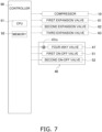
- the refrigeration cycle apparatus 1 includes a controller 90 (see Fig. 3 ) to cause internal devices to implement the operation described above.
- the controller 90 is, for example, a computer.
- the computer includes, for example, a control arithmetic unit and a storage unit.
- the control arithmetic unit may be a processor.
- the controller 90 includes a CPU 91, which is a processor.
- the control arithmetic unit reads a program stored in the storage unit and executes the program to perform predetermined processing, such as image processing, arithmetic processing, or sequential processing.
- the control arithmetic unit can also execute programs to record results of arithmetic operations onto the storage unit and to read information stored in the storage unit.
- the storage unit may be used as a database.
- Memory 92 is included as the storage unit in the controller 90.
- the controller 90 controls the compressor 10, the first expansion valve 61, the second expansion valve 64, the third expansion valve 63, and the switching mechanism 40.
- the controller 90 controls the four-way valve 46 and six valves (the first on-off valve 51, the second on-off valve 52, the third on-off valve 53, the fourth on-off valve 54, the fifth on-off valve 55, and the sixth on-off valve 56) such that switching of the switching mechanism 40 is controlled.
- the six valves may each be an electromagnetic valve that is capable of switching between the opened state and the closed state in accordance with a signal from the controller 90.
- the controller 90 sets the four-way valve 46 into the state illustrated in Fig. 1 , in which the a-port 46a communicates with the b-port 46b, and the c-port 46c communicates with the d-port 46d.
- the controller 90 sets the on-off valves into the state in which the first on-off valve 51 and the second on-off valve 52 are closed, and the other on-off valves (the third on-off valve 53, the fourth on-off valve 54, the fifth on-off valve 55, and the sixth on-off valve 56) are opened.
- the controller 90 When a transition from the first connection state to the third connection state takes place, the controller 90 causes the four on-off valves (the third on-off valve 53, the fourth on-off valve 54, the fifth on-off valve 55, and the sixth on-off valve 56) to close, with the four-way valve 46 remaining in the first connection state. The controller 90 then causes the first on-off valve 51 and the second on-off valve 52 to open. When a transition from the third connection state to the second connection state takes place, the controller 90 causes the first on-off valve 51 and the second on-off valve 52 to close. The controller 90 then sets the four-way valve 46 into the state illustrated in Fig.
- the controller 90 causes the four on-off valves (the third on-off valve 53, the fourth on-off valve 54, the fifth on-off valve 55, and the sixth on-off valve 56) to open.
- the controller 90 sets the four-way valve 46 into the state illustrated in Fig. 2 .
- the controller 90 sets the on-off valves into the state in which the first on-off valve 51 and the second on-off valve 52 are closed, and the other on-off valves (the third on-off valve 53, the fourth on-off valve 54, the fifth on-off valve 55, and the sixth on-off valve 56) are opened.
- the controller 90 causes the four on-off valves (the third on-off valve 53, the fourth on-off valve 54, the fifth on-off valve 55, and the sixth on-off valve 56) to close, with the four-way valve 46 remaining in the second connection state.
- the controller 90 then causes the first on-off valve 51 and the second on-off valve 52 to open.
- the controller 90 causes the first on-off valve 51 and the second on-off valve 52 to close.
- the controller 90 then sets the four-way valve 46 into the state illustrated in Fig. 1 and causes the four on-off valves (the third on-off valve 53, the fourth on-off valve 54, the fifth on-off valve 55, and the sixth on-off valve 56) to open.
- a refrigeration cycle apparatus 1 according to a second embodiment includes a compressor 10, a first heat exchanger 20, second heat exchangers 30, and a switching mechanism 40.
- the overview of the refrigeration cycle apparatus 1 according to the first embodiment has been described above under the heading "(1) Overview", which also holds true for the refrigeration cycle apparatus 1 according to the second embodiment and will not be further elaborated here.
- the switching mechanism 40 of the refrigeration cycle apparatus 1 includes a first port 41, a second port 42, a third port 43, and a fourth port 44.
- Refrigerant is compressed by the compressor 10 and then flows into the first port 41.
- the second port 42 communicates with the first heat exchanger 20.
- the refrigerant flows through the third port 43 and is then sucked into the compressor 10.
- the refrigeration cycle apparatus 1 includes a receiver 11, which forms a connection between the third port 43 and an inlet of the compressor 10.
- the fourth port 44 communicates with the second heat exchangers 30.
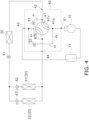
- the switching mechanism 40 in the first connection state is as illustrated in Fig. 4 , in which the first port 41 communicates with the second port 42, and the third port 43 communicates with the fourth port 44.
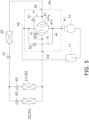
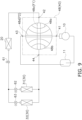
- the switching mechanism 40 in the third connection state is as illustrated in Fig. 5 , in which the second port 42 communicates with the fourth port 44, and the first port 41 communicates with the third port 43.
- the switching mechanism 40 in the second connection state is as illustrated in Fig. 6 , in which the first port 41 communicates with the fourth port 44, and the second port 42 communicates with the third port 43.
- the switching mechanism 40 includes a four-way valve 47, a first on-off valve 51, a second on-off valve 52, a first bypass pipe P1, and a second bypass pipe P2.
- the four-way valve 47 is a rotary-type switching valve including a valve element 47v that rotates within the valve. That is, the four-way valve 47 is a rotary valve.
- the valve element 47v includes a first inner flow path 47a and a second inner flow path 47b.
- the valve element 47v is powered by a motor 47m (see Fig. 7 ) to rotate.
- the valve element 47v of the four-way valve 47 rotates 90 degrees to enable switching between the first connection state and the second connection state.
- the valve element 47v of the four-way valve 47 can rotate 90 degrees to effect a transition from one state (in which the first port 41 communicates with the second port 42, and the third port 43 communicates with the fourth port 44) to another state (in which the first port 41 communicates with the fourth port 44, and the second port 42 communicates with the third port 43).
- the valve element 47v of the four-way valve 47 can rotate 45 degrees to effect a transition from the first connection state to the third connection state or a transition from the second connection state to the third connection state.
- the first bypass pipe P1 and the first on-off valve 51 are included in a first channel F1.
- the second bypass pipe P2 and the second on-off valve 52 are included in a second channel F2.
- the first bypass pipe P1 communicates with the second port 42 and the fourth port 44.
- the second bypass pipe P2 communicates with the first port 41 and the third port 43.
- the first on-off valve 51 is provided to the first bypass pipe P1.
- the second on-off valve 52 is provided to the second bypass pipe P2.
- the first bypass pipe P1 in the first connection state and the second connection state is closed by the first on-off valve 51 of the first channel F1.
- the second bypass pipe P2 in the first connection state and the second connection state is closed by the second on-off valve 52 of the second channel F2.
- the first on-off valve 51 and the second on-off valve 52 are opened, and the first bypass pipe P1 and the second bypass pipe P2 are opened accordingly.
- circuit configuration of the refrigeration cycle apparatus 1 according to the first embodiment and the circuit configuration of the refrigeration cycle apparatus 1 according to the second embodiment is in the internal configuration of the switching mechanism 40, and the circuit configuration in the second embodiment is otherwise identical to the circuit configuration in the first embodiment.
- the circuit configuration of the refrigeration cycle apparatus 1 according to the second embodiment and the flow of refrigeration cycle apparatus in the circuit will not be further elaborated here.
- switching between the first connection state and the second connection state is performed to enable switching between the first cycle and the second cycle.
- the switching mechanism 40 goes through the third connection state while making a transition from the first connection state to the second connection state or while making a transition from the second connection state to the first connection state.
- the valve element 47v rotates 45 degrees to effect a transition from the first connection state to the third connection state or a transition from the second connection state to the third connection state. Once the valve element 47v completes a 45-degree turn, the first inner flow path 47a and the second inner flow path 47b are connected to none of the four ports (the first port 41, the second port 42, the third port 43, and the fourth port 44).
- valve element 47v does not provide interconnection between the four ports (the first port 41, the second port 42, the third port 43, and the fourth port 44).
- the switching mechanism 40 opens the first on-off valve 51 and the second on-off valve 52 after the rotation of the valve element 47v.
- the switching mechanism 40 in the second embodiment goes through the third connection state, the difference between the pressure of refrigerant in the first heat exchanger 20 and the pressure of refrigerant in the second heat exchangers 31 and 32 (the second heat exchangers 30) is reduced or eliminated, as has been described above in relation to the first embodiment.
- the switching mechanism 40 in the second embodiment goes through the third connection state, the difference between the pressure of refrigerant flowing through regions located downstream of the outlet of the compressor 10 and the pressure of refrigerant flowing through regions located upstream of the inlet of the compressor 10 is reduced or eliminated, as has been described above in relation to the first embodiment.
- the refrigeration cycle apparatus 1 includes a controller 90 (see Fig. 7 ) to cause internal devices to implement the operation described above.
- a CPU91 and memory 92 are included as a processor and a storage unit, respectively, in the controller 90 according to the second embodiment, as in the controller 90 according to the first embodiment.
- the difference between the controller 90 according to the first embodiment and the controller 90 according to the second embodiment is in the control of the switching mechanism 40.
- the controller 90 according to the second embodiment controls the four-way valve 47, the first on-off valve 51, and the second on-off valve 52 such that switching of the switching mechanism 40 is controlled.
- the first on-off valve 51 and the second on-off valve 52 may each be an electromagnetic valve that is capable of switching between the opened state and the closed state in accordance with a signal from the controller 90.
- the motor 47m provided to the four-way valve 47 may be a stepping motor capable of adjusting the angle of rotation in accordance with a signal from the controller 90.
- the controller 90 sets the four-way valve 47 into the state illustrated in Fig. 4 , in which the first port 41 communicates with the second port 42, and the third port 43 communicates with the fourth port 44.
- the first on-off valve 51 and the second on-off valve 52 in the first connection state are kept in the closed state.
- the controller 90 controls the motor 47m in such a manner that the valve element 47v of the four-way valve 47 rotates 45 degrees (see Fig. 5 ).
- the controller 90 then causes the first on-off valve 51 and the second on-off valve 52 to open.
- the controller 90 When a transition from the third connection state to the second connection state takes place, the controller 90 causes the first on-off valve 51 and the second on-off valve 52 to close. The controller 90 then causes the valve element 47v of the four-way valve 47 to rotate 45 degrees, where a 90-degree turn relative to the valve element 47v in the first connection state is made.
- the switching mechanism 40 is thus brought into the state illustrated in Fig. 6 , in which the first port 41 communicates with the fourth port 44, and the third port 43 communicates with the second port 42.
- the controller 90 may, for example, set the four-way valve 47 into the state illustrated in Fig. 6 .
- the first on-off valve 51 and the second on-off valve 52 in the second connection state are kept in the closed state.
- the controller 90 controls the motor 47m in such a manner that the valve element 47v of the four-way valve 47 rotates 45 degrees (see Fig. 5 ).
- the controller 90 then causes the first on-off valve 51 and the second on-off valve 52 to open.
- the controller 90 causes the first on-off valve 51 and the second on-off valve 52 to close.
- the controller 90 then causes the valve element 47v of the four-way valve 47 to rotate 45 degrees, where a 90-degree turn relative to the valve element 47v in the first connection state is made.
- the switching mechanism 40 is thus brought into the state illustrated in Fig. 4 , in which the first port 41 communicates with the fourth port 44, and the third port 43 communicates with the second port 42.
- valve element 47v described above rotates clockwise to effect a transition from the first connection state to the second connection state and rotates counterclockwise to effect a transition from the second connection state to the first connection state. It is not required that the rotation of the valve element 47v be controlled in the manner mentioned above. In some embodiments, the valve element 47v under the control of the controller 90 rotates clockwise to effect a transition from the first connection state to the second connection state and rotates clockwise to effect a transition from the second connection state to the first connection state.
- a refrigeration cycle apparatus 1 according to a third embodiment includes a compressor 10, a first heat exchanger 20, second heat exchangers 30, and a switching mechanism 40.
- the overview of the refrigeration cycle apparatus 1 according to the first embodiment has been described above under the heading "(1) Overview", which also holds true for the refrigeration cycle apparatus 1 according to the third embodiment and will not be further elaborated here.
- the switching mechanism 40 of the refrigeration cycle apparatus 1 includes a first port 41, a second port 42, a third port 43, and a fourth port 44.
- Refrigerant is compressed by the compressor 10 and then flows into the first port 41.
- the second port 42 communicates with the first heat exchanger 20.
- the refrigerant flows through the third port 43 and is then sucked into the compressor 10.
- the refrigeration cycle apparatus 1 includes a receiver 11, which forms a connection between the third port 43 and an inlet of the compressor 10.
- the fourth port 44 communicates with the second heat exchangers 30.
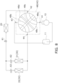
- the switching mechanism 40 in the first connection state is as illustrated in Fig. 8 , in which the first port 41 communicates with the second port 42, and the third port 43 communicates with the fourth port 44.
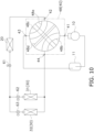
- the switching mechanism 40 in the third connection state is as illustrated in Fig. 9 , in which the second port 42 communicates with the second port 42, and the first port 41 communicates with the third port 43.
- the switching mechanism 40 in the second connection state is as illustrated in Fig. 10 , in which the first port 41 communicates with the fourth port 44, and the second port 42 communicates with the third port 43.
- the switching mechanism 40 includes a four-way valve 48.
- the first port 41, the second port 42, the third port 43, and the fourth port 44 of the switching mechanism 40 are also regarded as a first port 41, a second port 42, a third port 43, and a fourth port 44 of the four-way valve 48.
- the four-way valve 48 is a rotary-type switching valve including a valve element 48v that rotates within the valve. That is, the four-way valve 48 is a rotary valve.
- the valve element 48v includes a first inner flow path 48a, a second inner flow path 48b, a first bypass channel 48c, and a second bypass channel 48d.
- the first inner flow path 48a, the second inner flow path 48b, the first bypass channel 48c, and the second bypass channel 48d are channels provided in the valve element 48v, which is rotatable.
- the four-way valve 48 is designed such that the first bypass channel 48c and each of the first inner flow path 48a, the second inner flow path 48b, and the second bypass channel 48d cross at different levels.
- the Cv value of the first bypass channel 48c is greater than the Cv value of the second bypass channel 48d.
- the valve element 48v is designed such that the flow path cross-sectional area of the first bypass channel 48c is greater than the flow path cross-sectional area of the second bypass channel 48d.
- the valve element 48v is powered by a motor 48m (see Fig. 11 ) to rotate.
- the valve element 48v of the four-way valve 48 rotates 90 degrees to enable switching between the first connection state and the second connection state.
- the valve element 48v of the four-way valve 48 can rotate 90 degrees to effect a transition from one state (in which the first port 41 communicates with the second port 42, and the third port 43 communicates with the fourth port 44) to another state (in which the first port 41 communicates with the fourth port 44, and the second port 42 communicates with the third port 43).
- the valve element 48v of the four-way valve 48 can rotate 45 degrees to effect a transition from the first connection state to the third connection state or a transition from the second connection state to the third connection state.
- valve element 48v rotates 90 degrees or 45 degrees
- the angle of rotation required for switching of the four-way valve 48 is not limited to these degrees.
- the switching of the four-way valve 48 is effected by rotation to a desired angle.
- the second port 42 communicates with the fourth port 44 through the first bypass channel 48c when the valve element 48v is in the state illustrated in Fig. 9 (the third connection state).
- the first port 41 communicates with the third port 43 through the second bypass channel 48d when the valve element 48v is in the state illustrated in Fig. 9 (the third connection state).
- neither the first bypass channel 48c nor the second bypass channel 48d is connected to the outside of the valve element 48v; that is, the first bypass channel 48c and the second bypass channel 48d are blocked.
- the first bypass channel 48c and the second bypass channel 48d in the third embodiment are thus analogous to the first channel F1 and the second channel F2, respectively.
- circuit configuration of the refrigeration cycle apparatus 1 according to the first embodiment and the circuit configuration of the refrigeration cycle apparatus 1 according to the third embodiment is in the internal configuration of the switching mechanism 40, and the circuit configuration in the third embodiment is otherwise identical to the circuit configuration in the first embodiment.
- the circuit configuration of the refrigeration cycle apparatus 1 according to the third embodiment and the flow of refrigeration cycle apparatus in the circuit will not be further elaborated here.
- switching between the first connection state and the second connection state is performed to enable switching between the first cycle and the second cycle.
- the switching mechanism 40 goes through the third connection state while making a transition from the first connection state to the second connection state or while making a transition from the second connection state to the first connection state.
- the valve element 48v rotates 45 degrees to effect a transition from the first connection state to the third connection state or a transition from the second connection state to the third connection state. Once the valve element 48v completes a 45-degree turn, the first inner flow path 48a and the second inner flow path 48b are connected to none of the four ports (the first port 41, the second port 42, the third port 43, and the fourth port 44).
- the four ports do not communicate with each other through either the first inner flow path 48a or the second inner flow path 48b.
- the switching mechanism 40 in the third connection state allows the second port 42 to communicate with the fourth port 44 through the first bypass channel 48c.
- the switching mechanism 40 in the third connection state also allows the first port 41 to communicate with the third port 43 through the second bypass channel 48d.
- the switching mechanism 40 in the third embodiment goes through the third connection state, the difference between the pressure of refrigerant in the first heat exchanger 20 and the pressure of refrigerant in the second heat exchangers 31 and 32 (the second heat exchangers 30) is reduced or eliminated, as has been described above in relation to the first embodiment.
- the switching mechanism 40 in the third embodiment goes through the third connection state, the difference between the pressure of refrigerant flowing through regions located downstream the outlet of the compressor 10 and the pressure of refrigerant flowing through regions located upstream of the inlet of the compressor 10 is reduced or eliminated, as has been described above in relation to the first embodiment.
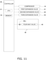
- the refrigeration cycle apparatus 1 includes a controller 90 (see Fig. 11 ) to cause internal devices to implement the operation described above.
- a CPU91 and memory 92 are included as a processor and a storage unit, respectively, in the controller 90 according to the third embodiment, as in the controller 90 according to the first embodiment.
- the difference between the controller 90 according to the first embodiment and the controller 90 according to the third embodiment is in the control of the switching mechanism 40.
- the controller 90 according to the third embodiment controls the four-way valve 48 such that switching of the switching mechanism 40 is controlled.
- the motor 48m provided to the four-way valve 48 may be a stepping motor capable of adjusting the angle of rotation in accordance with a signal from the controller 90. Signals of different frequencies may be used such that the rotational speed of the stepping motor provided as the motor 48m may be changed in accordance with the frequency of the signal input to the motor 48m.
- a different approach may be adopted to change the rotational speed of the motor 48m.
- gears for transmitting rotation of the motor 48m may be disposed, in which case the rotational speed can be changed in accordance with the gear ratio.
- the refrigeration cycle apparatus 1 is configured such that the rotational speed decreases when there is a significant difference between the pressure of refrigerant in the first heat exchanger 20 and the pressure of refrigerant in the second heat exchangers 30.
- This feature of the refrigeration cycle apparatus 1 offers the following advantage: the lower the rotational speed is, the longer the duration of the third connection state is.
- the refrigeration cycle apparatus 1 is configured such that the rotational speed increases when there is a little difference between the pressure of refrigerant in the first heat exchanger 20 and the pressure of refrigerant in the second heat exchangers 30.
- This feature of the refrigeration cycle apparatus 1 offers the following advantage: the higher the rotational speed is, the shorter the time it takes to enable switching between the first connection state and the second connection state is.
- the controller 90 sets the four-way valve 48 into the state illustrated in Fig. 8 , in which the first port 41 communicates with the second port 42, and the third port 43 communicates with the fourth port 44.
- the controller 90 controls the motor 48m in such a manner that the valve element 48v of the four-way valve 48 rotates 45 degrees (see Fig. 9 ).
- the controller 90 causes the valve element 48v of the four-way valve 48 to rotate 45 degrees, where a 90-degree turn relative to the valve element 48v in the first connection state is made.
- the switching mechanism 40 is thus brought into the state illustrated in Fig. 10 , in which the first port 41 communicates with the fourth port 44, and the third port 43 communicates with the second port 42.
- the controller 90 sets the four-way valve 48 into the state illustrated in Fig. 10 .
- the controller 90 controls the motor 48m in such a manner that the valve element 48v of the four-way valve 48 rotates 45 degrees (see Fig. 9 ).
- the controller 90 causes the valve element 48v of the four-way valve 48 to rotate 45 degrees, where a 90-degree turn relative to the valve element 48v in the first connection state is made.
- the switching mechanism 40 is thus brought into the state illustrated in Fig. 8 , in which the first port 41 communicates with the fourth port 44, and the third port 43 communicates with the second port 42.
- valve element 48v described above rotates clockwise to effect a transition from the first connection state to the second connection state and rotates counterclockwise to effect a transition from the second connection state to the first connection state. It is not required that the rotation of the valve element 48v be controlled in the manner mentioned above. In some embodiments, the valve element 48v under the control of the controller 90 rotates clockwise to effect a transition from the first connection state to the second connection state and rotates clockwise to effect a transition from the second connection state to the first connection state.
- the refrigeration cycle apparatus 1 uses carbon dioxide as refrigerant and is configured such that refrigerant in a supercritical state is discharged from the compressor 10. It is not required that refrigerant brought into a supercritical state in the refrigeration cycle apparatus 1 be carbon dioxide.
- the refrigerant to be used in the refrigeration cycle apparatus 1 may be a fluorocarbon refrigerant.
- the refrigeration cycle apparatus 1 may use R23 as refrigerant and may be configured such that refrigerant in a supercritical state is discharged from the compressor 10.
- the refrigeration cycle apparatus 1 according to each of the first, second, and third embodiments described above is configured such that refrigerant in a supercritical state is discharged from the compressor 10. It is not required that refrigerant in a supercritical state be discharged from the compressor 10, and the refrigeration cycle apparatus 1 may be configured such that refrigerant in gaseous form is discharged from the compressor 10.
- the refrigeration cycle apparatus 1 goes through the third connection state while the switching mechanism 40 of the refrigeration cycle apparatus 1 performs switching between the first connection state and the second connection state of the refrigeration cycle apparatus 1.
- the first channel F1 provides intercommunication between the first heat exchanger 20 and the second heat exchangers 30.
- the refrigeration cycle apparatus 1 is configured such that the difference between the pressure of refrigerant in the first heat exchanger 20 and the pressure of refrigerant in the second heat exchangers 30 is reduced at the time of switching between the first connection state and the second connection state.
- the switching mechanism 40 of the refrigeration cycle apparatus 1 changes the intercommunication between four ports (the first port 41, the second port 42, the third port 43, and the fourth port 44) to enable switching among the first connection state, the second connection state, and the third connection state.
- refrigerant is allowed to flow through the second port 42 and the fourth port 44 such that the refrigerant can flow into and out of the first heat exchanger 20 and the second heat exchangers 30.
- the refrigerant in the first heat exchanger 20 or the refrigerant in the second heat exchangers 30 is decompressed due to a transition to the third connection state. This eliminates or reduces the possibility that refrigerant in the first heat exchanger 20 or the second heat exchangers 30 will flow out in large quantity into a low-pressure site.
- refrigerant is allowed to flow through the first bypass pipe P1 and the first on-off valve 51, that is, through the first channel F1 such that the refrigerant can flow into and out of the first heat exchanger 20 and the second heat exchangers 30.
- the high-pressure refrigerant in the first heat exchanger 20 and the high-pressure refrigerant in the second heat exchangers 30 are decompressed accordingly. This eliminates or reduces the possibility that a large quantity of refrigerant will flow out of the first heat exchanger 20 and into a low-pressure site such as the receiver 11 or the intake side of the compressor 10 when a transition to the second connection state is completed.
- the first embodiment and the second embodiment each adopt such a simple configuration or, more specifically, the first bypass pipe P1 and the first on-off valve 51 to eliminate or reduce the possibility that a large quantity of refrigerant will flow into the receiver 11 or the intake side of the compressor 10 at the time of switching between the first connection state and the second connection state.
- the refrigeration cycle apparatus 1 While the switching mechanism 40 performs switching between the first connection state and the second connection state, the refrigeration cycle apparatus 1 according the first embodiment or the second embodiment is brought into the third connection state, in which the second channel F2 provides interconnection between the intake side (located upstream of the inlet) of the compressor 10 and the discharge side (located downstream of the outlet) of the compressor 10. Consequently, refrigerant on the discharge side of the compressor 10 is decompressed. In this way, the refrigeration cycle apparatus 1 addresses problems associated with a flow of refrigerant from the discharge side of the compressor 10 to a low-pressure site at the time of switching between the first connection state and the second connection state.
- the effect of reducing noise is an advantage of reducing the flow of refrigerant from the discharge side of the compressor 10 to a low-pressure.
- refrigerant is allowed to flow through the second bypass pipe P2 and the second on-off valve 52, that is, through the second channel F2 such that the refrigerant can flow from the discharge side of the compressor 10 and into the intake side of the compressor 10.
- the pressure on the discharge side of the compressor 10 is reduced accordingly. This eliminates or reduces the possibility that an upsurge in the flow of refrigerant from the discharge side of the compressor 10 to a low-pressure site will occur when a transition to the first connection state or to the second connection state is completed.
- the first embodiment and the second embodiment each adopt such a simple configuration or, more specifically, the second bypass pipe P2 and the second on-off valve 52 to reduce the flow of refrigerant from the discharge side of the compressor 10 when a switching between the first connection state and the second connection state is performed.
- refrigerant is allowed to flow through the first bypass channel 48c, that is, the first channel F1 such that the refrigerant can flow into and out of the first heat exchanger 20 and the second heat exchangers 30.
- the high-pressure refrigerant in the first heat exchanger 20 and the high-pressure refrigerant in the second heat exchangers 30 are decompressed accordingly. This eliminates or reduces the possibility that a large quantity of refrigerant will flow out of the first heat exchanger 20 and into a low-pressure site such as the receiver 11 or the intake side of the compressor 10 when a transition to the second connection state is completed.
- the third embodiment adopts such a simple configuration or, more specifically, the first bypass channel 48c to eliminate or reduce the possibility that a large quantity of refrigerant will flow into the receiver 11 or the intake side of the compressor 10 at the time of switching between the first connection state and the second connection state.
- the refrigeration cycle apparatus 1 When the refrigeration cycle apparatus 1 according to the third embodiment is in the third connection state, refrigerant is allowed to flow through the second bypass channel 48d, that is, the second channel F2 such that the refrigerant can flow from the discharge side of the compressor 10 and into the intake side of the compressor 10.
- the pressure on the discharge side of the compressor 10 is reduced accordingly. This eliminates or reduces the possibility that an upsurge in the flow of refrigerant from the discharge side of the compressor 10 to a low-pressure site will occur when a transition to the first connection state or to the second connection state is completed.
- the third embodiment adopts such a simple configuration or, more specifically, the second bypass channel 48d to reduce the flow of refrigerant from the discharge side of the compressor 10 when a switching between the first connection state and the second connection state is performed.
- the refrigeration cycle apparatus 1 is configured such that the Cv value of the first bypass channel 48c is greater than the Cv value of the second bypass channel 48d. It is thus ensured that the time it takes to reduce the difference in the pressure of refrigerant in the first heat exchanger 20 and the pressure of refrigerant in the second heat exchangers 30 will not be much longer than the time it takes to reduce the pressure difference between the discharge side and the intake side of the compressor 10. In other words, it is ensured that the time required to eliminate or reduce the pressure difference through the use of the first bypass channel 48c will not be much longer than the time required to eliminate or reduce the pressure difference through the use of the second bypass channel 48d. The duration of the third connection state will be shorter than if the Cv value of the first bypass channel 48c is equal to the Cv value of the second bypass channel 48d.
- the refrigeration cycle apparatus 1 according to the first embodiment and the refrigeration cycle apparatus 1 according to the second embodiment may be configured such that the Cv value of the first channel F1 is greater than the Cv value of the second channel F2. Effects equivalent to those produced by the refrigeration cycle apparatus 1 according to the third embodiment may be achieved accordingly.
- the switching mechanism 40 of the refrigeration cycle apparatus 1 may be a rotary valve designed such that the rotational speed of the valve element 48v is changeable.
- the refrigeration cycle apparatus 1 is configured such that the rotational speed decreases when there is a significant difference between the pressure of refrigerant in the first heat exchanger 20 and the pressure of refrigerant in the second heat exchangers 30. The lower the rotational speed is, the longer the duration of the third connection state is.
- the refrigeration cycle apparatus 1 can operate in a manner so as to eliminate or reduce the pressure difference to a satisfactory degree no matter how large the pressure difference is.
- a pressure sensor may be disposed on the discharge side of the compressor 10 to measure the pressure of refrigerant in the first heat exchanger 20 or the pressure of refrigerant in each second heat exchanger 30, whichever is higher.
- the controller 90 may be configured to acquire the measurements such that the rotational speed of the switching mechanism 40 is able to be changed in accordance with the pressure of refrigerant in the first heat exchanger 20 or the pressure of refrigerant in each second heat exchanger 30, whichever is higher.
- the second port 42 communicates with the fourth port 44 through the first bypass channel 48c.
- This enables a reduction in the difference between the pressure of refrigerant in a portion being part of the refrigerant circuit and connected to the second port 42 and the pressure of refrigerant in a portion being part of the refrigerant circuit and connected to the fourth port 44.
- the first bypass channel 48c of the four-way valve 48 is conducive to reducing the flow of refrigerant from the relevant portion of the refrigerant circuit (the portion connected to the second port 42 or the portion connected to the fourth port 44) to a low-pressure site.
- the first port 41 communicates with the third port 43 through the second bypass channel 48d.
- This enables a reduction in the difference between the pressure of refrigerant in a portion being part of the refrigerant circuit and connected to the first port 41 and the pressure of refrigerant in a portion being part of the refrigerant circuit and connected to the third port 43.
- the second bypass channel 483 of the four-way valve 48 is conducive to reducing the flow of refrigerant from the relevant portion of the refrigerant circuit (the portion connected to the first port 41 or the portion connected to the third port 43) to a low-pressure site.
- the four-way valve 48 according to the third embodiment is configured such that the Cv value of the first bypass channel 48c is greater than the Cv value of the second bypass channel 48d. It can be prevent that the time required to eliminate or reduce the pressure difference through the use of the first bypass channel 48c will not be much longer than the time required to eliminate or reduce the pressure difference through the use of the second bypass channel 48d. Consequently, the duration of the third connection state will be shorter than if the Cv value of the first bypass channel 48c is equal to the Cv value of the second bypass channel 48d.
Landscapes
- Engineering & Computer Science (AREA)
- General Engineering & Computer Science (AREA)
- Physics & Mathematics (AREA)
- Mechanical Engineering (AREA)
- Thermal Sciences (AREA)
- Fluid Mechanics (AREA)
- Compression-Type Refrigeration Machines With Reversible Cycles (AREA)
- Multiple-Way Valves (AREA)
Claims (12)
- Kältekreislaufvorrichtung (1), umfassend:einen Kompressor (10), der Kältemittel ansaugt, das Kältemittel komprimiert und dann das Kältemittel ausstößt;einen ersten Wärmetauscher (20), der in einem ersten Kreislauf als ein Kühler arbeitet und der in einem zweiten Kreislauf als ein Verdampfer arbeitet;einen zweiten Wärmetauscher (30), der in dem ersten Kreislauf als ein Verdampfer arbeitet und der in dem zweiten Kreislauf als ein Kühler arbeitet; undeinen Schaltmechanismus (40) einschließlich eines ersten Kanals (F1) und konfiguriert zum Durchführen eines Umschaltens zwischen einem ersten Verbindungszustand, einem zweiten Verbindungszustand und einem dritten Verbindungszustand, wobeiin dem ersten Verbindungszustand die Kältekreislaufvorrichtung wiederholt den ersten Kreislauf durchführt, in dem Kältemittel durch den Kompressor, den ersten Wärmetauscher, den zweiten Wärmetauscher und den Kompressor in dieser Reihenfolge fließt,in dem zweiten Verbindungszustand die Kältekreislaufvorrichtung wiederholt den zweiten Kreislauf durchführt, in dem Kältemittel durch den Kompressor, den zweiten Wärmetauscher, den ersten Wärmetauscher und den Kompressor in dieser Reihenfolge fließt, undin dem dritten Verbindungszustand ein Durchgang zwischen dem Kompressor (10) und dem ersten Wärmetauscher (20) und ein Durchgang zwischen dem Kompressor (10) und dem zweiten Wärmetauscher (30) geschlossen sind, und der erste Kanal (F1) in der Kältekreislaufvorrichtung so konfiguriert ist, dass er eine Verbindung zwischen dem ersten Wärmetauscher und dem zweiten Wärmetauscher bereitstellt,wobei in dem ersten Verbindungszustand und in dem zweiten Verbindungszustand der erste Kanal (F1) so konfiguriert ist, dass er keine Verbindung zwischen dem ersten Wärmetauscher (20) und dem zweiten Wärmetauscher (30) bereitstellt.
- Kältekreislaufvorrichtung (1) nach Anspruch 1, wobeider Schaltmechanismus einen ersten Anschluss (41), einen zweiten Anschluss (42), einen dritten Anschluss (43) und einen vierten Anschluss (44) einschließt,in den ersten Anschluss (41) durch den Kompressor komprimiertes Kältemittel hinein fließt,der zweite Anschluss (42) mit dem ersten Wärmetauscher in Verbindung steht,aus dem dritten Anschluss (43) das in den Kompressor anzusaugende Kältemittel hinaus fließt,der vierte Anschluss (44) mit dem zweiten Wärmetauscher in Verbindung steht,in dem ersten Verbindungszustand der erste Anschluss mit dem zweiten Anschluss in Verbindung steht und der dritte Anschluss mit dem vierten Anschluss in Verbindung steht,in dem zweiten Verbindungszustand der erste Anschluss mit dem vierten Anschluss in Verbindung steht und der zweite Anschluss mit dem dritten Anschluss in Verbindung steht, undin dem dritten Verbindungszustand der zweite Anschluss mit dem vierten Anschluss in Verbindung steht.
- Kältekreislaufvorrichtung (1) nach Anspruch 2, wobeider erste Kanal (F1) einschließteine erste Bypass-Leitung (P1), über die der zweite Anschluss (42) mit dem vierten Anschluss (44) in Verbindung steht, undein erstes Ein-Aus-Ventil (51), das an der ersten Bypass-Leitung bereitgestellt ist, um ein Umschalten zwischen einem Öffnen und Schließen der ersten Bypass-Leitung zu ermöglichen,in dem ersten Verbindungszustand und in dem zweiten Verbindungszustand die erste Bypass-Leitung (P1) des ersten Kanals (F1) geschlossen ist, undin dem dritten Verbindungszustand die erste Bypass-Leitung (P1) des ersten Kanals (F1) geöffnet ist.
- Kältekreislaufvorrichtung (1) nach Anspruch 2 oder 3, weiter umfassend einen zweiten Kanal (F2), über den der erste Anschluss (41) in dem dritten Verbindungszustand mit dem dritten Anschluss (43) in Verbindung steht.
- Kältekreislaufvorrichtung (1) nach Anspruch 4, wobeider zweite Kanal (F2) einschließteine zweite Bypass-Leitung (P2), über die der erste Anschluss (41) mit dem dritten Anschluss (43) in Verbindung steht, undein zweites Ein-Aus-Ventil (52), das an der zweiten Bypass-Leitung bereitgestellt ist, um ein Umschalten zwischen einem Öffnen und Schließen der zweiten Bypass-Leitung zu ermöglichen,in dem ersten Verbindungszustand und in dem zweiten Verbindungszustand das zweite Ein-Aus-Ventil die zweite Bypass-Leitung des zweiten Kanals schließt, undin dem dritten Verbindungszustand das zweite Ein-Aus-Ventil die zweite Bypass-Leitung des zweiten Kanals öffnet.
- Kältekreislaufvorrichtung (1) nach Anspruch 2, wobeider Schaltmechanismus einen ersten Bypass-Kanal (48c) einschließt, der der erste Kanal ist,in dem dritten Verbindungszustand der zweite Anschluss (42) über den ersten Bypass-Kanal (48c) mit dem vierten Anschluss (44) in Verbindung steht, und der Schaltmechanismus so konfiguriert ist, dassin dem ersten Verbindungszustand und in dem zweiten Verbindungszustand der erste Bypass-Kanal (48c) blockiert ist.
- Kältekreislaufvorrichtung (1) nach Anspruch 6, wobeider Schaltmechanismus einen zweiten Bypass-Kanal (48d) einschließt,in dem dritten Verbindungszustand der erste Anschluss (41) mit dem dritten Anschluss (43) über den zweiten Bypass-Kanal (48d) in Verbindung steht und der Schaltmechanismus so konfiguriert ist, dassin dem ersten Verbindungszustand und in dem zweiten Verbindungszustand der zweite Bypass-Kanal (48d) blockiert ist.
- Kältekreislaufvorrichtung (1) nach Anspruch 7, wobei ein Cv-Wert des ersten Bypass-Kanals größer ist als ein Cv-Wert des zweiten Bypass-Kanals.
- Kältekreislaufvorrichtung (1) nach einem der Ansprüche 6 bis 8, wobei der Schaltmechanismus ein Drehventil ist, dessen Drehzahl veränderbar ist.
- Kältekreislaufvorrichtung (1) nach Anspruch 1, wobei der Schaltmechanismus (40) ein Vierwegeventil (48) einschließt, umfassend:einen ersten Anschluss;einen zweiten Anschluss;einen dritten Anschluss;einen vierten Anschluss; undeinen ersten Bypass-Kanal, wobeiin dem ersten Verbindungszustand der Schaltmechanismus so konfiguriert ist, dass
der erste Anschluss mit dem zweiten Anschluss in Verbindung steht und der dritte Anschluss mit dem vierten Anschluss in Verbindung steht und das Vierwegeventil den ersten Bypass-Kanal schließt, undin dem zweiten Verbindungszustand,
der erste Anschluss mit dem vierten Anschluss in Verbindung steht und der zweite Anschluss mit dem dritten Anschluss in Verbindung steht, unddas Vierwegeventil den ersten Bypass-Kanal schließt, undin dem dritten Verbindungszustand der zweite Anschluss mit dem vierten Anschluss über den ersten Bypass-Kanal in Verbindung steht. - Kältekreislaufvorrichtung (1) nach Anspruch 10, wobei das Vierwegeventil (48) weiter einen zweiten Bypass-Kanal umfasst, wobei der Schaltmechanismus so konfiguriert ist, dassin dem ersten Verbindungszustand,
der erste Anschluss mit dem zweiten Anschluss in Verbindung steht und der dritte Anschluss mit dem vierten Anschluss in Verbindung steht, unddas Vierwegeventil den ersten Bypass-Kanal und den zweiten Bypass-Kanal schließt,in dem zweiten Verbindungszustand,
der erste Anschluss mit dem vierten Anschluss in Verbindung steht und der zweite Anschluss mit dem dritten Anschluss in Verbindung steht, unddas Vierwegeventil den ersten Bypass-Kanal und den zweiten Bypass-Kanal schließt,in dem dritten Verbindungszustand,der zweite Anschluss mit dem vierten Anschluss über den ersten Bypass-Kanal in Verbindung steht undder erste Anschluss mit dem dritten Anschluss über den zweiten Bypass-Kanal in Verbindung steht. - Kältekreislaufvorrichtung (1) nach Anspruch 11, wobei ein Cv-Wert des ersten Bypass-Kanals größer ist als ein Cv-Wert des zweiten Bypass-Kanals.
Applications Claiming Priority (2)
| Application Number | Priority Date | Filing Date | Title |
|---|---|---|---|
| JP2019180596A JP7332882B2 (ja) | 2019-09-30 | 2019-09-30 | 冷凍サイクル装置及び四方弁 |
| PCT/JP2020/036324 WO2021065730A1 (ja) | 2019-09-30 | 2020-09-25 | 冷凍サイクル装置及び四方弁 |
Publications (3)
| Publication Number | Publication Date |
|---|---|
| EP4040076A1 EP4040076A1 (de) | 2022-08-10 |
| EP4040076A4 EP4040076A4 (de) | 2023-03-08 |
| EP4040076B1 true EP4040076B1 (de) | 2024-05-15 |
Family
ID=75270608
Family Applications (1)
| Application Number | Title | Priority Date | Filing Date |
|---|---|---|---|
| EP20873293.3A Active EP4040076B1 (de) | 2019-09-30 | 2020-09-25 | Kältekreislaufvorrichtung und vierwegeventil |
Country Status (5)
| Country | Link |
|---|---|
| US (1) | US12163707B2 (de) |
| EP (1) | EP4040076B1 (de) |
| JP (1) | JP7332882B2 (de) |
| CN (1) | CN114556033B (de) |
| WO (1) | WO2021065730A1 (de) |
Families Citing this family (4)
| Publication number | Priority date | Publication date | Assignee | Title |
|---|---|---|---|---|
| DE102020130488A1 (de) * | 2019-12-16 | 2021-06-17 | ECO Holding 1 GmbH | Vorrichtung zur Handhabung von Fluid innerhalb eines zumindest teilweise elektrisch angetriebenen Fahrzeugs |
| JP7203178B1 (ja) | 2021-10-28 | 2023-01-12 | マレリ株式会社 | 流路切換弁及び冷却水回路 |
| CN115539668B (zh) * | 2022-08-31 | 2025-12-19 | 青岛海尔空调器有限总公司 | 四通阀以及包含该四通阀的空调器 |
| JP7658602B2 (ja) | 2023-01-19 | 2025-04-08 | 株式会社不二工機 | マルチポートバルブ |
Family Cites Families (24)
| Publication number | Priority date | Publication date | Assignee | Title |
|---|---|---|---|---|
| JPH06194007A (ja) * | 1992-10-30 | 1994-07-15 | Nippondenso Co Ltd | 流路切替バルブとそれを使用する空調装置 |
| JPH09287844A (ja) * | 1996-04-18 | 1997-11-04 | Matsushita Refrig Co Ltd | 空気調和機 |
| US6289931B1 (en) * | 2000-01-19 | 2001-09-18 | Emerson Electric Co. | Cycle reversing valve for use in heat pumps |
| JP2002018357A (ja) * | 2000-07-11 | 2002-01-22 | Sasakura Engineering Co Ltd | 低周波音波の発生装置 |
| JP4786822B2 (ja) * | 2001-05-24 | 2011-10-05 | 株式会社鷺宮製作所 | 電動式四方切換弁および冷凍サイクル装置 |
| WO2003072985A1 (en) * | 2002-02-27 | 2003-09-04 | Aser Tech Co., Ltd | Four-way reversing valve |
| JP4385698B2 (ja) * | 2003-09-25 | 2009-12-16 | 三菱電機株式会社 | 空気調和機 |
| US7152416B2 (en) * | 2004-09-08 | 2006-12-26 | Carrier Corporation | Hot gas bypass through four-way reversing valve |
| US7275384B2 (en) * | 2004-09-16 | 2007-10-02 | Carrier Corporation | Heat pump with reheat circuit |
| US7895850B2 (en) * | 2005-04-15 | 2011-03-01 | Comforture, L.P. | Modulating proportioning reversing valve |
| KR20060114964A (ko) | 2005-05-03 | 2006-11-08 | 삼성전자주식회사 | 냉장고 및 그 제어 방법 |
| JP2007205681A (ja) * | 2006-02-03 | 2007-08-16 | Toshiba Corp | 冷蔵庫 |
| KR101180207B1 (ko) * | 2006-09-01 | 2012-09-10 | 엘지전자 주식회사 | 수냉식 공기조화기 |
| CN201032314Y (zh) * | 2007-05-24 | 2008-03-05 | 珠海格力电器股份有限公司 | 冷媒流向转换装置及具有该装置的热水多联机 |
| JP5420869B2 (ja) | 2008-09-12 | 2014-02-19 | ニチハ株式会社 | 無機質系化粧建築板およびその製造方法 |
| FR2950678B1 (fr) * | 2009-09-30 | 2011-10-21 | Aldes Aeraulique | Installation de ventilation mecanique controlee de type double flux thermodynamique reversible avec production d'eau chaude sanitaire |
| WO2011048724A1 (ja) * | 2009-10-22 | 2011-04-28 | ダイキン工業株式会社 | 流路切換弁、及びそれを備えた空気調和機 |
| CN103380334B (zh) * | 2011-02-22 | 2016-03-16 | 日立空调·家用电器株式会社 | 冷冻循环装置 |
| JP2013124847A (ja) * | 2011-12-16 | 2013-06-24 | Calsonic Kansei Corp | 流路切替弁、及びその流路切替弁を備えた車両用空気調和装置 |
| JP2014211291A (ja) * | 2013-04-19 | 2014-11-13 | ダイキン工業株式会社 | 冷媒流路切換弁 |
| JP6442515B2 (ja) * | 2014-01-29 | 2018-12-19 | 上▲海▼高迪▲亜▼▲電▼子系▲統▼有限公司Shanghai Goldair Electricsystem Co., Ltd. | 低圧力降下及び低漏れ性の回転式四方切換弁 |
| JP6320060B2 (ja) * | 2014-01-31 | 2018-05-09 | 三菱電機株式会社 | 冷凍サイクル装置 |
| US10830502B2 (en) * | 2016-09-13 | 2020-11-10 | Mitsubishi Electric Corporation | Air conditioner |
| JP2018123972A (ja) * | 2017-01-30 | 2018-08-09 | ダイキン工業株式会社 | 冷凍装置 |
-
2019
- 2019-09-30 JP JP2019180596A patent/JP7332882B2/ja active Active
-
2020
- 2020-09-25 CN CN202080068314.9A patent/CN114556033B/zh active Active
- 2020-09-25 EP EP20873293.3A patent/EP4040076B1/de active Active
- 2020-09-25 WO PCT/JP2020/036324 patent/WO2021065730A1/ja not_active Ceased
-
2022
- 2022-03-29 US US17/707,220 patent/US12163707B2/en active Active
Also Published As
| Publication number | Publication date |
|---|---|
| WO2021065730A1 (ja) | 2021-04-08 |
| EP4040076A1 (de) | 2022-08-10 |
| JP7332882B2 (ja) | 2023-08-24 |
| JP2021055943A (ja) | 2021-04-08 |
| US12163707B2 (en) | 2024-12-10 |
| CN114556033B (zh) | 2023-08-11 |
| US20220221204A1 (en) | 2022-07-14 |
| EP4040076A4 (de) | 2023-03-08 |
| CN114556033A (zh) | 2022-05-27 |
Similar Documents
| Publication | Publication Date | Title |
|---|---|---|
| EP4040076B1 (de) | Kältekreislaufvorrichtung und vierwegeventil | |
| US6026654A (en) | Multi-unit air conditioner having a by-pass section for adjusting a flow rate of refrigerant | |
| CN116045555A (zh) | 用于空调器的气液分离装置、方法及空调器 | |
| EP4585869A1 (de) | Wärmepumpensystem | |
| US6314742B1 (en) | Double-tube type heat exchanger and refrigerating machine using the heat | |
| US12072131B2 (en) | Heat exchanger design for climate control system | |
| KR20250065651A (ko) | 히트 펌프 시스템 및 4방 밸브 | |
| CN115031444A (zh) | 热泵系统 | |
| CN217686006U (zh) | 节流换热器和空调器 | |
| CN216976986U (zh) | 室外机及换热系统 | |
| CN115479371B (zh) | 空调停电补偿功能的分流控制方法、系统及空调器 | |
| CN212339678U (zh) | 空调器 | |
| JP2008537773A (ja) | 環境に優しい冷媒を用いる場合に使用する三方サービス弁を備えた冷媒サイクル | |
| CN115264793A (zh) | 用于控制空调节能的方法、装置、空调和存储介质 | |
| CN208504807U (zh) | 四通换向阀组、流体换向系统及空调 | |
| CN220771427U (zh) | 一种节流换向器 | |
| CN217357638U (zh) | 换热器和空调器 | |
| CN222887443U (zh) | 一种热泵及其热水化霜系统 | |
| CN222669001U (zh) | 用于冷媒的多通阀、热管理系统及车辆 | |
| CN210603950U (zh) | 室内空调性能测试设备 | |
| CN119642439B (zh) | 热泵系统、增焓补气控制方法、装置、设备及存储介质 | |
| CN217357651U (zh) | 单向阀、换热器和空调器 | |
| KR100798525B1 (ko) | 냉난방 겸용 공기조화장치 | |
| JP7423819B2 (ja) | 冷凍サイクル装置 | |
| CN112440656B (zh) | 一种空调系统 |
Legal Events
| Date | Code | Title | Description |
|---|---|---|---|
| STAA | Information on the status of an ep patent application or granted ep patent |
Free format text: STATUS: THE INTERNATIONAL PUBLICATION HAS BEEN MADE |
|
| PUAI | Public reference made under article 153(3) epc to a published international application that has entered the european phase |
Free format text: ORIGINAL CODE: 0009012 |
|
| STAA | Information on the status of an ep patent application or granted ep patent |
Free format text: STATUS: REQUEST FOR EXAMINATION WAS MADE |
|
| 17P | Request for examination filed |
Effective date: 20220419 |
|
| AK | Designated contracting states |
Kind code of ref document: A1 Designated state(s): AL AT BE BG CH CY CZ DE DK EE ES FI FR GB GR HR HU IE IS IT LI LT LU LV MC MK MT NL NO PL PT RO RS SE SI SK SM TR |
|
| DAV | Request for validation of the european patent (deleted) | ||
| DAX | Request for extension of the european patent (deleted) | ||
| RAP3 | Party data changed (applicant data changed or rights of an application transferred) |
Owner name: DAIKIN INDUSTRIES, LTD. |
|
| A4 | Supplementary search report drawn up and despatched |
Effective date: 20230203 |
|
| RIC1 | Information provided on ipc code assigned before grant |
Ipc: F25B 1/00 20060101ALI20230130BHEP Ipc: F25B 41/26 20210101ALI20230130BHEP Ipc: F25B 13/00 20060101AFI20230130BHEP |
|
| P01 | Opt-out of the competence of the unified patent court (upc) registered |
Effective date: 20230525 |
|
| GRAP | Despatch of communication of intention to grant a patent |
Free format text: ORIGINAL CODE: EPIDOSNIGR1 |
|
| STAA | Information on the status of an ep patent application or granted ep patent |
Free format text: STATUS: GRANT OF PATENT IS INTENDED |
|
| INTG | Intention to grant announced |
Effective date: 20231206 |
|
| GRAS | Grant fee paid |
Free format text: ORIGINAL CODE: EPIDOSNIGR3 |
|
| GRAA | (expected) grant |
Free format text: ORIGINAL CODE: 0009210 |
|
| STAA | Information on the status of an ep patent application or granted ep patent |
Free format text: STATUS: THE PATENT HAS BEEN GRANTED |
|
| AK | Designated contracting states |
Kind code of ref document: B1 Designated state(s): AL AT BE BG CH CY CZ DE DK EE ES FI FR GB GR HR HU IE IS IT LI LT LU LV MC MK MT NL NO PL PT RO RS SE SI SK SM TR |
|
| REG | Reference to a national code |
Ref country code: CH Ref legal event code: EP |
|
| REG | Reference to a national code |
Ref country code: DE Ref legal event code: R096 Ref document number: 602020031100 Country of ref document: DE |
|
| REG | Reference to a national code |
Ref country code: IE Ref legal event code: FG4D |
|
| REG | Reference to a national code |
Ref country code: LT Ref legal event code: MG9D |
|
| REG | Reference to a national code |
Ref country code: NL Ref legal event code: MP Effective date: 20240515 |
|
| PG25 | Lapsed in a contracting state [announced via postgrant information from national office to epo] |
Ref country code: IS Free format text: LAPSE BECAUSE OF FAILURE TO SUBMIT A TRANSLATION OF THE DESCRIPTION OR TO PAY THE FEE WITHIN THE PRESCRIBED TIME-LIMIT Effective date: 20240915 |
|
| PG25 | Lapsed in a contracting state [announced via postgrant information from national office to epo] |
Ref country code: BG Free format text: LAPSE BECAUSE OF FAILURE TO SUBMIT A TRANSLATION OF THE DESCRIPTION OR TO PAY THE FEE WITHIN THE PRESCRIBED TIME-LIMIT Effective date: 20240515 |
|
| PG25 | Lapsed in a contracting state [announced via postgrant information from national office to epo] |
Ref country code: FI Free format text: LAPSE BECAUSE OF FAILURE TO SUBMIT A TRANSLATION OF THE DESCRIPTION OR TO PAY THE FEE WITHIN THE PRESCRIBED TIME-LIMIT Effective date: 20240515 Ref country code: HR Free format text: LAPSE BECAUSE OF FAILURE TO SUBMIT A TRANSLATION OF THE DESCRIPTION OR TO PAY THE FEE WITHIN THE PRESCRIBED TIME-LIMIT Effective date: 20240515 |
|
| PG25 | Lapsed in a contracting state [announced via postgrant information from national office to epo] |
Ref country code: GR Free format text: LAPSE BECAUSE OF FAILURE TO SUBMIT A TRANSLATION OF THE DESCRIPTION OR TO PAY THE FEE WITHIN THE PRESCRIBED TIME-LIMIT Effective date: 20240816 |
|
| PG25 | Lapsed in a contracting state [announced via postgrant information from national office to epo] |
Ref country code: PT Free format text: LAPSE BECAUSE OF FAILURE TO SUBMIT A TRANSLATION OF THE DESCRIPTION OR TO PAY THE FEE WITHIN THE PRESCRIBED TIME-LIMIT Effective date: 20240916 |
|
| REG | Reference to a national code |
Ref country code: AT Ref legal event code: MK05 Ref document number: 1687213 Country of ref document: AT Kind code of ref document: T Effective date: 20240515 |
|
| PG25 | Lapsed in a contracting state [announced via postgrant information from national office to epo] |
Ref country code: NL Free format text: LAPSE BECAUSE OF FAILURE TO SUBMIT A TRANSLATION OF THE DESCRIPTION OR TO PAY THE FEE WITHIN THE PRESCRIBED TIME-LIMIT Effective date: 20240515 |
|
| PG25 | Lapsed in a contracting state [announced via postgrant information from national office to epo] |
Ref country code: ES Free format text: LAPSE BECAUSE OF FAILURE TO SUBMIT A TRANSLATION OF THE DESCRIPTION OR TO PAY THE FEE WITHIN THE PRESCRIBED TIME-LIMIT Effective date: 20240515 |
|
| PG25 | Lapsed in a contracting state [announced via postgrant information from national office to epo] |
Ref country code: AT Free format text: LAPSE BECAUSE OF FAILURE TO SUBMIT A TRANSLATION OF THE DESCRIPTION OR TO PAY THE FEE WITHIN THE PRESCRIBED TIME-LIMIT Effective date: 20240515 |
|
| PG25 | Lapsed in a contracting state [announced via postgrant information from national office to epo] |
Ref country code: PL Free format text: LAPSE BECAUSE OF FAILURE TO SUBMIT A TRANSLATION OF THE DESCRIPTION OR TO PAY THE FEE WITHIN THE PRESCRIBED TIME-LIMIT Effective date: 20240515 |
|
| PG25 | Lapsed in a contracting state [announced via postgrant information from national office to epo] |
Ref country code: LV Free format text: LAPSE BECAUSE OF FAILURE TO SUBMIT A TRANSLATION OF THE DESCRIPTION OR TO PAY THE FEE WITHIN THE PRESCRIBED TIME-LIMIT Effective date: 20240515 |
|
| PG25 | Lapsed in a contracting state [announced via postgrant information from national office to epo] |
Ref country code: PT Free format text: LAPSE BECAUSE OF FAILURE TO SUBMIT A TRANSLATION OF THE DESCRIPTION OR TO PAY THE FEE WITHIN THE PRESCRIBED TIME-LIMIT Effective date: 20240916 Ref country code: PL Free format text: LAPSE BECAUSE OF FAILURE TO SUBMIT A TRANSLATION OF THE DESCRIPTION OR TO PAY THE FEE WITHIN THE PRESCRIBED TIME-LIMIT Effective date: 20240515 Ref country code: NO Free format text: LAPSE BECAUSE OF FAILURE TO SUBMIT A TRANSLATION OF THE DESCRIPTION OR TO PAY THE FEE WITHIN THE PRESCRIBED TIME-LIMIT Effective date: 20240815 Ref country code: NL Free format text: LAPSE BECAUSE OF FAILURE TO SUBMIT A TRANSLATION OF THE DESCRIPTION OR TO PAY THE FEE WITHIN THE PRESCRIBED TIME-LIMIT Effective date: 20240515 Ref country code: LV Free format text: LAPSE BECAUSE OF FAILURE TO SUBMIT A TRANSLATION OF THE DESCRIPTION OR TO PAY THE FEE WITHIN THE PRESCRIBED TIME-LIMIT Effective date: 20240515 Ref country code: IS Free format text: LAPSE BECAUSE OF FAILURE TO SUBMIT A TRANSLATION OF THE DESCRIPTION OR TO PAY THE FEE WITHIN THE PRESCRIBED TIME-LIMIT Effective date: 20240915 Ref country code: HR Free format text: LAPSE BECAUSE OF FAILURE TO SUBMIT A TRANSLATION OF THE DESCRIPTION OR TO PAY THE FEE WITHIN THE PRESCRIBED TIME-LIMIT Effective date: 20240515 Ref country code: GR Free format text: LAPSE BECAUSE OF FAILURE TO SUBMIT A TRANSLATION OF THE DESCRIPTION OR TO PAY THE FEE WITHIN THE PRESCRIBED TIME-LIMIT Effective date: 20240816 Ref country code: FI Free format text: LAPSE BECAUSE OF FAILURE TO SUBMIT A TRANSLATION OF THE DESCRIPTION OR TO PAY THE FEE WITHIN THE PRESCRIBED TIME-LIMIT Effective date: 20240515 Ref country code: ES Free format text: LAPSE BECAUSE OF FAILURE TO SUBMIT A TRANSLATION OF THE DESCRIPTION OR TO PAY THE FEE WITHIN THE PRESCRIBED TIME-LIMIT Effective date: 20240515 Ref country code: BG Free format text: LAPSE BECAUSE OF FAILURE TO SUBMIT A TRANSLATION OF THE DESCRIPTION OR TO PAY THE FEE WITHIN THE PRESCRIBED TIME-LIMIT Effective date: 20240515 Ref country code: AT Free format text: LAPSE BECAUSE OF FAILURE TO SUBMIT A TRANSLATION OF THE DESCRIPTION OR TO PAY THE FEE WITHIN THE PRESCRIBED TIME-LIMIT Effective date: 20240515 Ref country code: RS Free format text: LAPSE BECAUSE OF FAILURE TO SUBMIT A TRANSLATION OF THE DESCRIPTION OR TO PAY THE FEE WITHIN THE PRESCRIBED TIME-LIMIT Effective date: 20240815 |
|
| PG25 | Lapsed in a contracting state [announced via postgrant information from national office to epo] |
Ref country code: DK Free format text: LAPSE BECAUSE OF FAILURE TO SUBMIT A TRANSLATION OF THE DESCRIPTION OR TO PAY THE FEE WITHIN THE PRESCRIBED TIME-LIMIT Effective date: 20240515 |
|
| PG25 | Lapsed in a contracting state [announced via postgrant information from national office to epo] |
Ref country code: EE Free format text: LAPSE BECAUSE OF FAILURE TO SUBMIT A TRANSLATION OF THE DESCRIPTION OR TO PAY THE FEE WITHIN THE PRESCRIBED TIME-LIMIT Effective date: 20240515 |
|
| PG25 | Lapsed in a contracting state [announced via postgrant information from national office to epo] |
Ref country code: CZ Free format text: LAPSE BECAUSE OF FAILURE TO SUBMIT A TRANSLATION OF THE DESCRIPTION OR TO PAY THE FEE WITHIN THE PRESCRIBED TIME-LIMIT Effective date: 20240515 |
|
| PG25 | Lapsed in a contracting state [announced via postgrant information from national office to epo] |
Ref country code: SK Free format text: LAPSE BECAUSE OF FAILURE TO SUBMIT A TRANSLATION OF THE DESCRIPTION OR TO PAY THE FEE WITHIN THE PRESCRIBED TIME-LIMIT Effective date: 20240515 Ref country code: RO Free format text: LAPSE BECAUSE OF FAILURE TO SUBMIT A TRANSLATION OF THE DESCRIPTION OR TO PAY THE FEE WITHIN THE PRESCRIBED TIME-LIMIT Effective date: 20240515 |
|
| PG25 | Lapsed in a contracting state [announced via postgrant information from national office to epo] |
Ref country code: SM Free format text: LAPSE BECAUSE OF FAILURE TO SUBMIT A TRANSLATION OF THE DESCRIPTION OR TO PAY THE FEE WITHIN THE PRESCRIBED TIME-LIMIT Effective date: 20240515 |
|
| PG25 | Lapsed in a contracting state [announced via postgrant information from national office to epo] |
Ref country code: SM Free format text: LAPSE BECAUSE OF FAILURE TO SUBMIT A TRANSLATION OF THE DESCRIPTION OR TO PAY THE FEE WITHIN THE PRESCRIBED TIME-LIMIT Effective date: 20240515 Ref country code: SK Free format text: LAPSE BECAUSE OF FAILURE TO SUBMIT A TRANSLATION OF THE DESCRIPTION OR TO PAY THE FEE WITHIN THE PRESCRIBED TIME-LIMIT Effective date: 20240515 Ref country code: RO Free format text: LAPSE BECAUSE OF FAILURE TO SUBMIT A TRANSLATION OF THE DESCRIPTION OR TO PAY THE FEE WITHIN THE PRESCRIBED TIME-LIMIT Effective date: 20240515 Ref country code: EE Free format text: LAPSE BECAUSE OF FAILURE TO SUBMIT A TRANSLATION OF THE DESCRIPTION OR TO PAY THE FEE WITHIN THE PRESCRIBED TIME-LIMIT Effective date: 20240515 Ref country code: DK Free format text: LAPSE BECAUSE OF FAILURE TO SUBMIT A TRANSLATION OF THE DESCRIPTION OR TO PAY THE FEE WITHIN THE PRESCRIBED TIME-LIMIT Effective date: 20240515 Ref country code: CZ Free format text: LAPSE BECAUSE OF FAILURE TO SUBMIT A TRANSLATION OF THE DESCRIPTION OR TO PAY THE FEE WITHIN THE PRESCRIBED TIME-LIMIT Effective date: 20240515 |
|
| PG25 | Lapsed in a contracting state [announced via postgrant information from national office to epo] |
Ref country code: IT Free format text: LAPSE BECAUSE OF FAILURE TO SUBMIT A TRANSLATION OF THE DESCRIPTION OR TO PAY THE FEE WITHIN THE PRESCRIBED TIME-LIMIT Effective date: 20240515 |
|
| REG | Reference to a national code |
Ref country code: DE Ref legal event code: R097 Ref document number: 602020031100 Country of ref document: DE |
|
| PLBE | No opposition filed within time limit |
Free format text: ORIGINAL CODE: 0009261 |
|
| STAA | Information on the status of an ep patent application or granted ep patent |
Free format text: STATUS: NO OPPOSITION FILED WITHIN TIME LIMIT |
|
| 26N | No opposition filed |
Effective date: 20250218 |
|
| PG25 | Lapsed in a contracting state [announced via postgrant information from national office to epo] |
Ref country code: SI Free format text: LAPSE BECAUSE OF FAILURE TO SUBMIT A TRANSLATION OF THE DESCRIPTION OR TO PAY THE FEE WITHIN THE PRESCRIBED TIME-LIMIT Effective date: 20240515 Ref country code: MC Free format text: LAPSE BECAUSE OF FAILURE TO SUBMIT A TRANSLATION OF THE DESCRIPTION OR TO PAY THE FEE WITHIN THE PRESCRIBED TIME-LIMIT Effective date: 20240515 |
|
| REG | Reference to a national code |
Ref country code: CH Ref legal event code: PL |
|
| PG25 | Lapsed in a contracting state [announced via postgrant information from national office to epo] |
Ref country code: LU Free format text: LAPSE BECAUSE OF NON-PAYMENT OF DUE FEES Effective date: 20240925 |
|
| REG | Reference to a national code |
Ref country code: BE Ref legal event code: MM Effective date: 20240930 |
|
| PG25 | Lapsed in a contracting state [announced via postgrant information from national office to epo] |
Ref country code: BE Free format text: LAPSE BECAUSE OF NON-PAYMENT OF DUE FEES Effective date: 20240930 |
|
| PG25 | Lapsed in a contracting state [announced via postgrant information from national office to epo] |
Ref country code: CH Free format text: LAPSE BECAUSE OF NON-PAYMENT OF DUE FEES Effective date: 20240930 |
|
| PG25 | Lapsed in a contracting state [announced via postgrant information from national office to epo] |
Ref country code: IE Free format text: LAPSE BECAUSE OF NON-PAYMENT OF DUE FEES Effective date: 20240925 |
|
| PG25 | Lapsed in a contracting state [announced via postgrant information from national office to epo] |
Ref country code: SE Free format text: LAPSE BECAUSE OF FAILURE TO SUBMIT A TRANSLATION OF THE DESCRIPTION OR TO PAY THE FEE WITHIN THE PRESCRIBED TIME-LIMIT Effective date: 20240515 |
|
| PGFP | Annual fee paid to national office [announced via postgrant information from national office to epo] |
Ref country code: DE Payment date: 20250919 Year of fee payment: 6 |
|
| PGFP | Annual fee paid to national office [announced via postgrant information from national office to epo] |
Ref country code: GB Payment date: 20250919 Year of fee payment: 6 |
|
| PGFP | Annual fee paid to national office [announced via postgrant information from national office to epo] |
Ref country code: FR Payment date: 20250922 Year of fee payment: 6 |
|
| PG25 | Lapsed in a contracting state [announced via postgrant information from national office to epo] |
Ref country code: CY Free format text: LAPSE BECAUSE OF FAILURE TO SUBMIT A TRANSLATION OF THE DESCRIPTION OR TO PAY THE FEE WITHIN THE PRESCRIBED TIME-LIMIT; INVALID AB INITIO Effective date: 20200925 |
|
| PG25 | Lapsed in a contracting state [announced via postgrant information from national office to epo] |
Ref country code: HU Free format text: LAPSE BECAUSE OF FAILURE TO SUBMIT A TRANSLATION OF THE DESCRIPTION OR TO PAY THE FEE WITHIN THE PRESCRIBED TIME-LIMIT; INVALID AB INITIO Effective date: 20200925 |