EP4040105B1 - Procédé de mesure de position de roue de véhicule et dispositif associé - Google Patents
Procédé de mesure de position de roue de véhicule et dispositif associé Download PDFInfo
- Publication number
- EP4040105B1 EP4040105B1 EP20871940.1A EP20871940A EP4040105B1 EP 4040105 B1 EP4040105 B1 EP 4040105B1 EP 20871940 A EP20871940 A EP 20871940A EP 4040105 B1 EP4040105 B1 EP 4040105B1
- Authority
- EP
- European Patent Office
- Prior art keywords
- measurement
- wheel assembly
- distance
- vehicle
- vehicle body
- Prior art date
- Legal status (The legal status is an assumption and is not a legal conclusion. Google has not performed a legal analysis and makes no representation as to the accuracy of the status listed.)
- Active
Links
Images




Classifications
-
- G—PHYSICS
- G01—MEASURING; TESTING
- G01B—MEASURING LENGTH, THICKNESS OR SIMILAR LINEAR DIMENSIONS; MEASURING ANGLES; MEASURING AREAS; MEASURING IRREGULARITIES OF SURFACES OR CONTOURS
- G01B11/00—Measuring arrangements characterised by the use of optical techniques
-
- G—PHYSICS
- G01—MEASURING; TESTING
- G01B—MEASURING LENGTH, THICKNESS OR SIMILAR LINEAR DIMENSIONS; MEASURING ANGLES; MEASURING AREAS; MEASURING IRREGULARITIES OF SURFACES OR CONTOURS
- G01B11/00—Measuring arrangements characterised by the use of optical techniques
- G01B11/26—Measuring arrangements characterised by the use of optical techniques for measuring angles or tapers; for testing the alignment of axes
-
- G—PHYSICS
- G01—MEASURING; TESTING
- G01B—MEASURING LENGTH, THICKNESS OR SIMILAR LINEAR DIMENSIONS; MEASURING ANGLES; MEASURING AREAS; MEASURING IRREGULARITIES OF SURFACES OR CONTOURS
- G01B11/00—Measuring arrangements characterised by the use of optical techniques
- G01B11/02—Measuring arrangements characterised by the use of optical techniques for measuring length, width or thickness
- G01B11/026—Measuring arrangements characterised by the use of optical techniques for measuring length, width or thickness by measuring distance between sensor and object
-
- G—PHYSICS
- G01—MEASURING; TESTING
- G01B—MEASURING LENGTH, THICKNESS OR SIMILAR LINEAR DIMENSIONS; MEASURING ANGLES; MEASURING AREAS; MEASURING IRREGULARITIES OF SURFACES OR CONTOURS
- G01B11/00—Measuring arrangements characterised by the use of optical techniques
- G01B11/02—Measuring arrangements characterised by the use of optical techniques for measuring length, width or thickness
- G01B11/06—Measuring arrangements characterised by the use of optical techniques for measuring length, width or thickness for measuring thickness ; e.g. of sheet material
- G01B11/0608—Height gauges
-
- G—PHYSICS
- G01—MEASURING; TESTING
- G01B—MEASURING LENGTH, THICKNESS OR SIMILAR LINEAR DIMENSIONS; MEASURING ANGLES; MEASURING AREAS; MEASURING IRREGULARITIES OF SURFACES OR CONTOURS
- G01B11/00—Measuring arrangements characterised by the use of optical techniques
- G01B11/14—Measuring arrangements characterised by the use of optical techniques for measuring distance or clearance between spaced objects or spaced apertures
-
- G—PHYSICS
- G01—MEASURING; TESTING
- G01B—MEASURING LENGTH, THICKNESS OR SIMILAR LINEAR DIMENSIONS; MEASURING ANGLES; MEASURING AREAS; MEASURING IRREGULARITIES OF SURFACES OR CONTOURS
- G01B11/00—Measuring arrangements characterised by the use of optical techniques
- G01B11/24—Measuring arrangements characterised by the use of optical techniques for measuring contours or curvatures
- G01B11/245—Measuring arrangements characterised by the use of optical techniques for measuring contours or curvatures using a plurality of fixed, simultaneously operating transducers
-
- G—PHYSICS
- G01—MEASURING; TESTING
- G01B—MEASURING LENGTH, THICKNESS OR SIMILAR LINEAR DIMENSIONS; MEASURING ANGLES; MEASURING AREAS; MEASURING IRREGULARITIES OF SURFACES OR CONTOURS
- G01B11/00—Measuring arrangements characterised by the use of optical techniques
- G01B11/26—Measuring arrangements characterised by the use of optical techniques for measuring angles or tapers; for testing the alignment of axes
- G01B11/275—Measuring arrangements characterised by the use of optical techniques for measuring angles or tapers; for testing the alignment of axes for testing wheel alignment
- G01B11/2755—Measuring arrangements characterised by the use of optical techniques for measuring angles or tapers; for testing the alignment of axes for testing wheel alignment using photoelectric detection means
-
- G—PHYSICS
- G01—MEASURING; TESTING
- G01B—MEASURING LENGTH, THICKNESS OR SIMILAR LINEAR DIMENSIONS; MEASURING ANGLES; MEASURING AREAS; MEASURING IRREGULARITIES OF SURFACES OR CONTOURS
- G01B5/00—Measuring arrangements characterised by the use of mechanical techniques
- G01B5/0025—Measuring of vehicle parts
-
- G—PHYSICS
- G01—MEASURING; TESTING
- G01M—TESTING STATIC OR DYNAMIC BALANCE OF MACHINES OR STRUCTURES; TESTING OF STRUCTURES OR APPARATUS, NOT OTHERWISE PROVIDED FOR
- G01M17/00—Testing of vehicles
- G01M17/007—Wheeled or endless-tracked vehicles
- G01M17/013—Wheels
-
- G—PHYSICS
- G01—MEASURING; TESTING
- G01M—TESTING STATIC OR DYNAMIC BALANCE OF MACHINES OR STRUCTURES; TESTING OF STRUCTURES OR APPARATUS, NOT OTHERWISE PROVIDED FOR
- G01M17/00—Testing of vehicles
- G01M17/007—Wheeled or endless-tracked vehicles
- G01M17/04—Suspension or damping
-
- G—PHYSICS
- G01—MEASURING; TESTING
- G01B—MEASURING LENGTH, THICKNESS OR SIMILAR LINEAR DIMENSIONS; MEASURING ANGLES; MEASURING AREAS; MEASURING IRREGULARITIES OF SURFACES OR CONTOURS
- G01B2210/00—Aspects not specifically covered by any group under G01B, e.g. of wheel alignment, caliper-like sensors
- G01B2210/10—Wheel alignment
- G01B2210/14—One or more cameras or other optical devices capable of acquiring a two-dimensional image
- G01B2210/146—Two or more cameras imaging the same area
-
- G—PHYSICS
- G01—MEASURING; TESTING
- G01B—MEASURING LENGTH, THICKNESS OR SIMILAR LINEAR DIMENSIONS; MEASURING ANGLES; MEASURING AREAS; MEASURING IRREGULARITIES OF SURFACES OR CONTOURS
- G01B2210/00—Aspects not specifically covered by any group under G01B, e.g. of wheel alignment, caliper-like sensors
- G01B2210/10—Wheel alignment
- G01B2210/28—Beam projector and related sensors, camera, inclinometer or other active sensing or projecting device
- G01B2210/283—Beam projectors and related sensors
- G01B2210/286—Projecting a light pattern on the wheel or vehicle body
Definitions
- the present invention belongs to a technical field that relates to a vehicle wheel assembly position measurement method and a vehicle wheel assembly position measurement apparatus for measuring a height position of a wheel assembly relative to a vehicle body.
- a measurement apparatus is disclosed in Patent Literature 1.
- a load cell is arranged to each member that supports respective wheel assembly of the vehicle from an outer side in a vehicle width direction. Then, the measurement apparatus uses each of the load cells to measure a load, which is generated when the wheel assembly attempts to move outward in the vehicle width direction while the wheel assembly rotates, so as to evaluate a degree of one-sided drift of the vehicle.
- a wheel alignment measurement apparatus for an automobile is disclosed in Patent Literature 2.
- Three laser displacement sensors for measuring a motion trajectory of an axle in a three-dimensional space are provided to a wheel-side sensor unit that is attached to the wheel side, and three reflectors corresponding to the three laser displacement sensors are provided to a platform-side sensor unit that is attached to a platform side. Then, the wheel alignment measurement apparatus of an automobile measures the motion trajectory of the axle in the three-dimensional space while adjusting and measuring distances between the laser displacement sensors and the reflectors.
- Patent Literature 2 In order to obtain the favorable steering stability during travel of the vehicle, it is preferred not to only consider the wheel alignment in a vehicle stationary state as in Patent Literature 2 but to also consider so-called dynamic wheel alignment during the travel of the vehicle is assumed as in Patent Literature 1.
- a height position of the wheel assembly relative to a vehicle body is changed by actuation of a suspension device.
- the wheel alignment is also changed according to this change in the height position of the wheel assembly.
- a change characteristic of the wheel alignment with respect to this change in the height position of the wheel assembly possibly differs from a targeted design characteristic due to individual variability and assembly variability of the suspension device.
- the height position of the wheel assembly relative to the vehicle body has to be measured. For this reason, it is preferred that the height position of the wheel assembly relative to the vehicle body can easily and accurately be measured.
- the present invention has been made in view of such a point and therefore has a purpose of providing a vehicle wheel assembly position measurement method and a vehicle wheel assembly position measurement apparatus capable of easily and accurately measure a height position of a wheel assembly relative to a vehicle body.
- the present invention provides, as a target, a vehicle wheel assembly position measurement method for measuring a height position of a wheel assembly relative to a vehicle body that includes: a distance measurement step of measuring a distance in a vehicle width direction between each of plural measurement points and a distance measuring instrument at at least three measurement positions in a circumferential direction on a lateral surface of a tire section of the wheel assembly, the distance measuring instrument being arranged on a lateral side of each of the measurement positions, and each of the plural measurement points being located on a specified line that crosses the lateral surface of the tire section from an inner circumferential end to an outer circumferential end; a vehicle body position measurement step of measuring a height position of a specified portion of the vehicle body by a vehicle body position measuring instrument; an approximate curve calculation step of calculating, at each of the measurement positions, an approximate curve in a graph on the basis of measurement data of each of the measurement points, at which the distance on the specified line is measured, a relationship between a position in an extending direction of the specified
- the distance measuring instrument capable of measuring wheel alignment measures the distance between each of the plural measurement points located on the specified line on the lateral surface of the tire section and the distance measuring instrument
- the position of the measurement point with the shortest distance is a position where the tire section bulges most outward in the vehicle width direction by an internal air pressure. It is considered that, when seen in the vehicle width direction, the position of the measurement point with the shortest distance at each of the at least three measurement positions is located on a concentric circle with the rotation center position of the wheel assembly being a center.
- the lateral surface of the tire section is usually provided with protrusions such as characters indicating tire specifications and a logo.
- protrusions such as characters indicating tire specifications and a logo.
- the position of the measurement point with the shortest distance differs from the position where the tire section bulges most outward in the vehicle width direction. As a result, it becomes impossible to accurately calculate the rotation center position of the wheel assembly from the position of such a measurement point.
- the approximate curve in the graph in which the relationship between the position in the extending direction of the specified line and the distance of each of the measurement points is plotted, is calculated on the basis of the measurement data of the respective measurement point, at which the distance on the specified line is measured. Even with the protrusion as described above, this approximate curve is similar to a curve without the protrusion. Accordingly, when the rotation center position of the wheel assembly is calculated from the specific position on the approximate curve (for example, the position where the distance is the shortest) at each of the at least three measurement positions, the rotation center position can accurately be calculated.
- the vehicle body position measuring instrument is added to a wheel alignment measurement apparatus that has conventionally been used, and thus the approximate curve calculation step, the rotation center position calculation step, and the wheel assembly height position calculation step can easily be executed by computer software. Therefore, it is possible to easily and accurately measure the height position of the wheel assembly relative to the vehicle body.
- the specific position is preferably a position where the distance is the shortest on the approximate curve.
- the distance measurement step is a step of irradiating the lateral surface of the tire section with light in a line shape along the specified line by using the distance measuring instrument and measuring a distance in the vehicle width direction between each of the measurement points located in the light irradiated portion of the lateral surface of the tire section and the distance measuring instrument.
- the distance measuring instrument can measure wheel alignment of the vehicle.
- This vehicle wheel assembly position measurement apparatus includes: a distance measuring instrument that is arranged on a lateral side of each of at least three measurement positions in a circumferential direction on a lateral surface of a tire section in the wheel assembly and measures a distance in a vehicle width direction to each of plural measurement points at the respective measurement position, each of the plural measurement points being located on a specified line that crosses the lateral surface of the tire section from an inner circumferential end to an outer circumferential end; a vehicle body position measuring instrument that measures a height position of a specified portion of the vehicle body; an approximate curve calculation section that calculates, at each of the measurement positions, an approximate curve in a graph on the basis of measurement data of each of the measurement points, at which the distance on the specified line is measured, a relationship between a position in an extending direction of the specified line and the distance of the respective measurement point being plotted in the graph;
- the specific position is preferably a position where the distance is the shortest on the approximate curve.
- the distance measuring instrument has: an irradiation section that irradiates the lateral surface of the tire section with light in a line shape along the specified line; and a measurement section that measures a distance in the vehicle width direction between each of the measurement points located in the light irradiated portion of the lateral surface of the tire section and the distance measuring instrument.
- the distance measuring instrument can measure wheel alignment of the vehicle.
- the vehicle wheel assembly position measurement method and the wheel assembly position measurement apparatus each calculate the approximate curve in the graph, in which the relationship between the position in the extending direction of the specified line and the distance of each of the measurement points is plotted, calculate the rotation center position of the wheel assembly from the specific position on the approximate curve of each of the at least three measurement positions, and calculate the height position of the wheel assembly relative to the vehicle body from the calculated rotation center position of the wheel assembly and the height position of the specified portion of the vehicle body measured by the vehicle body position measuring instrument. In this way, it is possible to easily and accurately measure the height position of the wheel assembly relative to the vehicle body.
- Fig. 1 illustrates a vehicle wheel assembly position measurement apparatus 1 according to the embodiment of the present invention.
- This wheel assembly position measurement apparatus 1 measures a height position of a wheel assembly 23 relative to a vehicle body 22 in a vehicle 21, and is arranged on a lateral side of each of the wheel assemblies 23 of the vehicle 21 that is arranged at a specified position.
- Each of the wheel assemblies 23 is supported by the vehicle body 22 via a suspension device, which is not illustrated.
- each of the wheel assemblies 23 is located on a wheel assembly drive unit 8 and can be rotated by this wheel assembly drive unit 8.
- the wheel assembly position measurement apparatuses 1, each of which corresponds to the respective wheel assembly 23, have the same configuration.
- the wheel assembly position measurement apparatus 1 that corresponds to one of the wheel assemblies 23 (here, a front right wheel assembly).
- front, rear, left, right, upper, and lower sides of the vehicle 21 (the vehicle body 22) will simply be referred to as front, rear, left, right, upper, and lower sides, respectively.
- the wheel assembly position measurement apparatus 1 includes first to third distance measuring instruments 2 to 4.
- the first to third distance measuring instruments 2 to 4 are arranged on lateral sides (here, right sides) of three measurement positions in a circumferential direction on a lateral surface (a lateral surface on an outer side in a vehicle width direction) of a tire section 23a of the wheel assembly 23.
- the first to third distance measuring instruments 2 to 4 each measure a distance in the vehicle width direction (a right-left direction) to each of plural measurement points located on respective one of specified lines L1, L2, L3, each of which crosses the lateral surface of the tire section 23a from an inner circumferential end to an outer circumferential end, at the respective measurement position.
- the first to third distance measuring instruments 2 to 4 are supported by a support member 7.
- the four or more measurement positions may be set on the lateral surface of the tire section 23a, and the distance measuring instruments, the number of which corresponds to the number of the measurement positions, may be provided.
- the three measurement positions are a first measurement position that is a lower and front portion in the lateral surface of the tire section 23a, a second measurement position that is a lower and rear portion in the lateral surface of the tire section 23a, and a third measurement position that is the uppermost portion in the lateral surface of the tire section 23a.
- the first to third measurement positions are positions that are spaced at substantially equal intervals in the circumferential direction.
- the specified lines L1, L2 at the first and second measurement positions extend horizontally at the substantially same height positions, and the specified line L3 at the third measurement position extends vertically.
- a rotation center position O of the wheel assembly 23 (a rotation center position of a wheel section 23b) is located on a downward extension line L3a of the specified line L3.
- the first distance measuring instrument 2 is arranged on a lateral side of the first measurement position
- the second distance measuring instrument 3 is arranged on a lateral side of the second measurement position
- the third distance measuring instrument 4 is arranged on a lateral side of the third measurement position.
- the first distance measuring instrument 2 has an irradiation section 2a and a measurement section 2b.
- the irradiation section 2a irradiates the lateral surface of the tire section 23a with light (here, a laser beam) in a line shape along the specified line L1.
- the measurement section 2b that measures a distance in the vehicle width direction between the first distance measuring instrument 2 and each of the measurement points located in a light irradiated portion in the lateral surface of the tire section 23a.
- the measurement section 2b has an imaging camera that is located on an upper side of the irradiation section 2a.
- the measurement section 2b can measure the above distance to a portion (that is, a measurement section) that is acquired by equally dividing the light irradiated portion into plural portions in an extending direction of the specified line L1.
- the second distance measuring instrument 3 has an irradiation section 3a and a measurement section 3b (an imaging camera).
- the irradiation section 3a irradiates the lateral surface of the tire section 23a with the light in the line shape along the specified line L2.
- the measurement section 3b measures a distance in the vehicle width direction between the second distance measuring instrument 3 and each of the measurement points located in the light irradiated portion in the lateral surface of the tire section 23a.
- the third distance measuring instrument 4 has an irradiation section 4a and a measurement section 4b (an imaging camera).
- the irradiation section 4a irradiates the lateral surface of the tire section 23a with the light in the line shape along the specified line L3.
- the measurement section 4b measures a distance in the vehicle width direction between the third distance measuring instrument 43 and each of the measurement points located in the light irradiated portion in the lateral surface of the tire section 23a.
- Each of the second and third distance measuring instruments 3, 4 has the same configuration as the first distance measuring instrument 2.
- the imaging camera in the measurement section 4b of the third distance measuring instrument 4 is located on a rear side of the irradiation section 4a, and captures an image of the light irradiated portion, which is irradiated by the irradiation section 4a, in the lateral surface of the tire section 23a obliquely backward.
- the wheel assembly position measurement apparatus 1 further includes a vehicle body position measuring instrument 5 that measures a height position of a specified portion in the vehicle body 22.
- the specified portion when seen in the vehicle width direction, the specified portion is the lowest point A (see Fig. 2 and Fig. 3 ) of a fender section 22a on an upward extension line L3b of the specified line L3.
- the vehicle body position measuring instrument 5 is supported by the support member 7 in a manner to be located on a lateral side of a portion including the lowest point A of the fender section 22a and on an upper side of the third distance measuring instrument 4.
- the specified portion when seen in the vehicle width direction, may be an outermost portion (a point B in Fig. 3 ) in the vehicle width direction of the fender section 22a on the extension line L3b of the specified line L3. Further alternatively, the specified portion may be any portion of the fender section 22a as long as the height position thereof can be measured.
- the vehicle body position measuring instrument 5 has the same configuration as the first to third distance measuring instruments 2 to 4, and has an irradiation section 5a and a measurement section 5b (an imaging camera).
- the irradiation section 5a irradiates the fender section 22a with the light in the line shape along the extension line L3b of the specified line L3.
- the measurement section 5b is located on a rear side of the irradiation section 5a, and measures a distance in the vehicle width direction between the vehicle body position measuring instrument 5 and each measurement point located in the light irradiated portion of the fender section 22a.
- a controller 11 receives measurement data of each of the measurement points, at which the distance on respective one of the specified lines L1, L2, L3 is measured by respective one of the first to third distance measuring instruments 2 to 4, at the measurement positions.
- the controller 11 also receives measurement data at each of the measurement points measured by the vehicle body position measuring instrument 5.
- the controller 11 is a controller (a processor) that has a well-known microcomputer as a base component, and includes a CPU, memory, an input/output bus, and the like.
- the CPU is a central processing unit that executes computer programs (including a basic control program such as an OS and an application program that is run on the OS to implement a particular function).
- the memory is configured to include RAM and ROM.
- the ROM stores the various computer programs, data, and the like.
- the RAM is memory provided with a processing area that is used when the CPU executes a series of processing.
- the input/output bus inputs/outputs an electric signal from/to the controller 11.
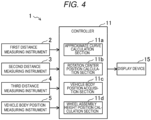
- the controller 11 is provided with an approximate curve calculation section 11a, a rotation center position calculation section 11b, a vehicle body position acquisition section 11c, and a wheel assembly height position calculation section 11d therein.
- the approximate curve calculation section 11a, the rotation center position calculation section 11b, the vehicle body position acquisition section 11c, and the wheel assembly height position calculation section 11d are operated as will be described below according to the computer program stored in the ROM.
- the approximate curve calculation section 11a calculates, at each of the measurement positions, an approximate curve (here, a quadratic approximate curve) in a graph, in which a relationship between a position of each of the measurement points in the extending direction of respective one of the specified lines L1, L2, L3 and the distance is plotted, on the basis of the measurement data of the respective measurement point, at which the distance on respective one of the specified lines L1, L2, L3 is measured.
- an approximate curve here, a quadratic approximate curve
- a substantially central portion between an inner circumferential end and an outer circumferential end bulges most outward in the vehicle width direction by an internal air pressure (see Fig. 3 ). That is, the substantially central portion on the specified lines L1, L2, L3 bulges most outward in the vehicle width direction.
- the position of the measurement point with the shortest distance on each of the specified lines L1, L2, L3 is a position that bulges most outward in the vehicle width direction. It is considered that, when seen in the vehicle width direction, the position of the measurement point with the shortest distance at each of the first to third measurement positions is located on a circle C (indicated by a broken line in Fig.
- the lateral surface of the tire section 23a is usually provided with protrusions such as characters indicating tire specifications and a logo.
- protrusions such as characters indicating tire specifications and a logo.
- the position of the measurement point with the shortest distance differs from the position where the tire section 23a bulges most outward in the vehicle width direction.
- the approximate curve calculation section 11a calculates, at each of the measurement positions, the approximate curve (the quadratic approximate curve) as described above on the basis of the measurement data of each of the measurement points, at which the distance on respective one of the specified lines L1, L2, L3 is measured.
- Fig. 5 illustrates an example of a graph in which, at the first measurement position, a relationship between a position X in the extending direction of the specified line L1 and a distance Y of each of the measurement points is plotted.
- the position of the measurement point with the shortest distance is x2 due to the protrusion, and is a position that is shifted from a position x1 where the tire section 23a bulges most outward in the vehicle width direction.
- the approximate curve is a curve that is minimum (the distance becomes the shortest) at x1, and a position where the curve is minimum is the position where the tire section 23a bulges most outward in the vehicle width direction.
- the approximate curve is illustrated in an exaggerated manner to facilitate understanding.
- the rotation center position calculation section 11b calculates the positions, at each of which the approximate curve is minimum (corresponding to a specific position on the approximate curve), at the first to third measurement positions, and then calculates the rotation center position O of the wheel assembly 23 from these positions, at each of which the approximate curve is minimum.
- the specific position on the approximate curve is not limited to the position where the approximate curve is minimum. However, from a perspective of further easily and accurately calculating the rotation center position O of the wheel assembly 23, it is preferred to set the position where the approximate curve is minimum as the specific position.
- a provisional rotation center position of wheel assembly 23 is calculated from the positions, at each of which the approximate curve is minimum, at the three measurement positions.
- the provisional rotation center position of the wheel assembly 23 is calculated for another combination of the three measurement positions. In this way, the provisional rotation center position of the wheel assembly 23 is calculated for all the combinations. Then, for example, an average position of all the provisional rotation center positions of the wheel assembly 23 is determined as the rotation center position O of the wheel assembly 23.
- the vehicle body position acquisition section 11c acquires a height position of the lowest point A of the fender section 22a (a specified portion of the vehicle body 22) on the extension line L3b of the specified line L3 from the measurement data of each of the measurement points by the vehicle body position measuring instrument 5.
- the fender section 22a is not provided with a protrusion like one in the tire section 23a. Accordingly, the height position of the lowest point A of the fender section 22a can easily be acquired from the measurement data of each of the measurement points measured by the vehicle body position measuring instrument 5 without calculating the approximate curve and the like.
- the wheel assembly height position calculation section 11d calculates the height position of the wheel assembly 23 relative to the vehicle body 22 from the rotation center position O of the wheel assembly 23, which is calculated by the rotation center position calculation section 11b, and the height position of the lowest point A of the fender section 22a, which is measured by the vehicle body position measuring instrument 5 (in detail, acquired by the vehicle body position acquisition section 11c).
- the controller 11 sends information on the height position of the wheel assembly 23 relative to the vehicle body 22, which is calculated by the wheel assembly height position calculation section 11d, to a display device 15 and causes the display device 15 to show the height position.
- Fig. 6 is a flowchart illustrating wheel assembly position measurement processing operation by the controller 11. This flowchart is started by a worker's switch operation, for example. With this switch operation, the distance is measured by each of the first to third distance measuring instruments 2 to 4 and the vehicle body position measuring instrument 5.
- first step S1 the measurement data of each of the measurement points on the specified lines L1, L2, L3 is input from the first to third distance measuring instruments 2 to 4.
- the measurement data of each of the measurement points on the extension line L3b of the specified line L3 is input from the vehicle body position measuring instrument 5.
- the approximate curve calculation section 11a calculates the approximate curve (the quadratic approximate curve) on the basis of the measurement data of each of the measurement points on the specified lines L1, L2, L3.
- the rotation center position calculation section 11b calculates the positions, at each of which the approximate curve is minimum, at the first to third measurement positions, and then calculates the rotation center position O of the wheel assembly 23 from these positions, at each of which the approximate curve is minimum.
- step S5 the vehicle body position acquisition section 11c acquires the height position of the lowest point A of the fender section 22a on the extension line L3b of the specified line L3 from the measurement data of each of the measurement points by the vehicle body position measuring instrument 5.
- the processing operation in step S5 may be executed at any timing as long as being executed after step S2 and before step S6, which will be described below.
- the wheel assembly height position calculation section 11d calculates the height position of the wheel assembly 23 relative to the vehicle body 22 from the rotation center position O of the wheel assembly 23, which is calculated by the rotation center position calculation section 11b, and the height position of the lowest point A of the fender section 22a, which is acquired by the vehicle body position acquisition section 11c.
- step S7 the display device 15 shows the height position of the wheel assembly 23 relative to the vehicle body 22, which is calculated in step S6, and thereafter the wheel assembly position measurement processing operation is terminated.
- the first to third distance measuring instruments 2 to 4 can each measure wheel alignment of the vehicle 21. That is, the first to third distance measuring instruments 2 to 4 are used in a wheel alignment measurement apparatus that has conventionally been used.
- the first and second distance measuring instruments 2, 3 can measure a toe angle. More specifically, the toe angle can be measured from a difference between the distances to the measurement points measured by the first and second distance measuring instruments 2, 3 at the positions, at each of which the lateral surface of the tire section 23a bulges most outward in the vehicle width direction, and a distance in a front-rear direction between both of the measurement points.
- the first to third distance measuring instruments 2 to 4 can measure a camber angle. More specifically, the camber angle can be measured from a difference between an average value of the distances to the measurement points, which are measured by the first and second distance measuring instruments 2, 3, at the positions, at each of which the lateral surface of the tire section 23a bulges most outward in the vehicle width direction and the distance to the measurement point, which is measured by the third distance measuring instrument 4, at the position where the lateral surface of the tire section 23a bulges most outward in the vehicle width direction, and from a distance in an up-down direction between the measurement point and any one of both of the measurement points for calculating the average value of the distances.
- the wheel assembly position measurement apparatus 1 in this embodiment is configured by adding the vehicle body position measuring instrument 5 and changing software for the controller 11 in the wheel alignment measurement apparatus that has conventionally been used. In this way, during the travel of the vehicle (when the wheel assembly 23 is rotationally driven by the wheel assembly drive unit 8), the wheel assembly position measurement apparatus 1 can measure the height position of the wheel assembly 23 relative to the vehicle body 22 while measuring the wheel alignment.
- the approximate curve in the graph, in which the position in the extending direction of respective one of the specified lines L1, L2, L3 and the distance of each of the measurement points is plotted, is calculated, the rotation center position O of the wheel assembly 23 is calculated from the positions, at each of which the approximate curve is minimum, at the first to third measurement positions, and the height position of the wheel assembly 23 relative to the vehicle body 22 is calculated from the calculated rotation center position O of the wheel assembly 23 and the height position of the lowest point A of the fender section 22a on the extension line L3b of the specified line L3, which is measured by the vehicle body position measuring instrument.
- the vehicle body position measuring instrument In this way, it is possible to easily and accurately measure the height position of the wheel assembly 23 relative to the vehicle body 22.
- the present invention is useful for the vehicle wheel assembly position measurement method and the vehicle wheel assembly position measurement apparatus for measuring the height position of the wheel assembly relative to the vehicle body.
Landscapes
- Physics & Mathematics (AREA)
- General Physics & Mathematics (AREA)
- Length Measuring Devices By Optical Means (AREA)
- Length Measuring Devices With Unspecified Measuring Means (AREA)
Claims (8)
- Un procédé de mesure de position d'ensemble roue de véhicule consistant à mesurer une position en hauteur d'un ensemble roue (23) par rapport à une carrosserie de véhicule (22), le procédé de mesure de position d'ensemble roue de véhicule comprenant :une étape de mesure de distance consistant à mesurer une distance dans une direction de largeur de véhicule entre chacun de plusieurs points de mesure et un instrument de mesure de distance (2, 3, 4) à au moins trois positions de mesure dans une direction circonférentielle sur une surface latérale d'une section de pneu (23a) de l'ensemble roue (23), l'instrument de mesure de distance (2, 3, 4) étant agencé sur un côté latéral de chacune des positions de mesure, et chacun des plusieurs points de mesure étant situé sur une ligne spécifiée (L1, L2, L3) qui traverse la surface latérale de la section de pneu (23a) depuis une extrémité circonférentielle intérieure à une extrémité circonférentielle extérieure ;une étape de mesure de position de carrosserie de véhicule consistant à mesurer une position en hauteur d'une partie spécifiée (A, B) de la carrosserie de véhicule (22) à l'aide d'un instrument de mesure de position de carrosserie de véhicule (5) ;une étape de calcul de courbe approximative consistant à calculer, à chacune des positions de mesure, une courbe approximative dans un graphique sur la base des données de mesure de chacun des points de mesure, où la distance sur la ligne spécifiée (L1, L2, L3) est mesurée, une relation entre une position (X) dans une direction d'extension de la ligne spécifiée (L1, L2, L3) et la distance (Y) du point de mesure respectif étant tracée dans le graphique ;une étape de calcul de position de centre de rotation consistant à calculer la position d'un centre de rotation (O) de l'ensemble roue (23) à partir d'une position spécifique sur la courbe approximative au niveau de chacune des trois positions de mesure au moins ; etune étape de calcul de position en hauteur d'ensemble roue consistant à calculer la position en hauteur de l'ensemble roue (23) par rapport à la carrosserie de véhicule (22) à partir de la position de centre de rotation (O) calculée dans l'étape de calcul de position de centre de rotation, et la position en hauteur de la partie spécifiée (A, B) de la carrosserie de véhicule (22) mesurée dans l'étape de mesure de position de carrosserie de véhicule.
- Le procédé de mesure de position d'ensemble roue de véhicule d'après la revendication 1,
sachant que la position spécifique est une position (x1) où la distance est la plus courte sur la courbe approximative. - Le procédé de mesure de position d'ensemble roue de véhicule d'après la revendication 1 ou 2,
sachant que l'étape de mesure de distance est une étape consistant à irradier la surface latérale de la section de pneu (23a) avec de la lumière en forme de ligne le long de la ligne spécifiée (L1, L2, L3) en utilisant l'instrument de mesure de distance (2, 3, 4), et à mesurer une distance dans la direction de la largeur de véhicule entre chacun des points de mesure situés dans la partie irradiée par la lumière de la surface latérale de la section de pneu (23a) et l'instrument de mesure de distance (2, 3, 4). - Le procédé de mesure de position d'ensemble roue de véhicule d'après l'une quelconque des revendications de 1 à 3,
sachant que l'instrument de mesure de distance (2, 3, 4) peut mesurer l'alignement des roues du véhicule. - Un appareil de mesure de position d'ensemble roue de véhicule (1) pour mesurer une position en hauteur d'un ensemble roue (23) par rapport à une carrosserie de véhicule (22), l'appareil de mesure de position d'ensemble roue de véhicule (1) comprenant :un instrument de mesure de distance (2, 3, 4) configuré pour être agencé sur un côté latéral de chacune d'au moins trois positions de mesure dans une direction circonférentielle sur une surface latérale d'une section de pneu (23a) dans l'ensemble roue (23), et pour mesurer une distance dans une direction de largeur de véhicule à chacun des points de mesure pluriels au niveau de la position de mesure respective, chacun des plusieurs points de mesure étant situé sur une ligne spécifiée (L1, L2, L3) qui traverse la surface latérale de la section de pneu (23a) depuis une extrémité circonférentielle intérieure à une extrémité circonférentielle extérieure ;un instrument de mesure de position de carrosserie de véhicule (5) configuré pour mesurer une position en hauteur d'une partie spécifiée (A, B) de la carrosserie de véhicule (22) ;une section de calcul de courbe approximative (11a) configurée pour calculer, à chacune des positions de mesure, une courbe approximative dans un graphique sur la base des données de mesure de chacun des points de mesure, où la distance sur la ligne spécifiée (L1, L2, L3) est mesurée, une relation entre une position (X) dans une direction d'extension de la ligne spécifiée (L1, L2, L3) et la distance (Y) du point de mesure respectif étant tracée dans le graphique ;une section de calcul de position de centre de rotation (11b) configurée pour calculer une position de centre de rotation (O) de l'ensemble roue (23) à partir d'une position spécifique sur la courbe approximative à chacune des trois positions de mesure au moins ; etune section de calcul de position en hauteur d'ensemble roue (11d) configurée pour calculer la position en hauteur de l'ensemble roue (23) par rapport à la carrosserie de véhicule (22) à partir de la position de centre de rotation (O) calculée par la section de calcul de position de centre de rotation (11b), et la position en hauteur de la partie spécifiée (A, B) de la carrosserie de véhicule (22) mesurée par l'instrument de mesure de position de carrosserie de véhicule (5).
- L'appareil de mesure de position d'ensemble roue de véhicule (1) d'après la revendication 5,
sachant que la position spécifique (x1) est une position où la distance est la plus courte sur la courbe approximative. - L'appareil de mesure de position d'ensemble roue de véhicule (1) d'après la revendication 5 ou 6,
sachant que l'instrument de mesure de distance (2, 3, 4) présente : une section d'irradiation (2a, 3a, 4a) configurée pour irradier la surface latérale de la section de pneu (23a) avec de la lumière en forme de ligne le long de la ligne spécifiée (L1, L2, L3) ; et une section de mesure (2b, 3b, 4b) configurée pour mesurer une distance dans la direction de la largeur de véhicule entre chacun des points de mesure situés dans la partie irradiée par la lumière de la surface latérale de la section du pneu (23a) et l'instrument de mesure de distance (2, 3, 4). - L'appareil de mesure de position d'ensemble roue de véhicule (1) d'après l'une quelconque des revendications de 5 à 7,
sachant que l'instrument de mesure de distance (2, 3, 4) peut mesurer l'alignement des roues du véhicule.
Applications Claiming Priority (2)
| Application Number | Priority Date | Filing Date | Title |
|---|---|---|---|
| JP2019178997A JP7310507B2 (ja) | 2019-09-30 | 2019-09-30 | 車両の車輪位置測定方法及びその装置 |
| PCT/JP2020/033458 WO2021065326A1 (fr) | 2019-09-30 | 2020-09-03 | Procédé et dispositif de mesure de position de roue de véhicule |
Publications (3)
| Publication Number | Publication Date |
|---|---|
| EP4040105A1 EP4040105A1 (fr) | 2022-08-10 |
| EP4040105A4 EP4040105A4 (fr) | 2023-10-18 |
| EP4040105B1 true EP4040105B1 (fr) | 2024-12-25 |
Family
ID=75272504
Family Applications (1)
| Application Number | Title | Priority Date | Filing Date |
|---|---|---|---|
| EP20871940.1A Active EP4040105B1 (fr) | 2019-09-30 | 2020-09-03 | Procédé de mesure de position de roue de véhicule et dispositif associé |
Country Status (6)
| Country | Link |
|---|---|
| US (1) | US11953315B2 (fr) |
| EP (1) | EP4040105B1 (fr) |
| JP (1) | JP7310507B2 (fr) |
| CN (1) | CN114450551B (fr) |
| MX (1) | MX2022003200A (fr) |
| WO (1) | WO2021065326A1 (fr) |
Families Citing this family (3)
| Publication number | Priority date | Publication date | Assignee | Title |
|---|---|---|---|---|
| CN115790514A (zh) * | 2022-11-03 | 2023-03-14 | 深圳市德驰微视技术有限公司 | 一种轮胎转角测量方法 |
| CN115930842B (zh) * | 2023-03-09 | 2023-05-16 | 荣成康派斯新能源车辆股份有限公司 | 一种房车车轮车轴定位仪及其车轮车轴定位检测方法 |
| FR3167441A1 (fr) * | 2024-10-14 | 2026-04-17 | Stellantis Auto Sas | Appareil et procede pour mesurer une position de roue sur un vehicule automobile |
Family Cites Families (22)
| Publication number | Priority date | Publication date | Assignee | Title |
|---|---|---|---|---|
| JPH03237307A (ja) | 1990-02-14 | 1991-10-23 | Saginomiya Seisakusho Inc | 自動車のホイールアライメント測定装置 |
| JP3421972B2 (ja) | 1993-05-19 | 2003-06-30 | 日産自動車株式会社 | 車両片流れ評価装置 |
| US5600435A (en) * | 1995-05-24 | 1997-02-04 | Fori Automation, Inc. | Intelligent sensor method and apparatus for an optical wheel alignment machine |
| DE19528798C2 (de) * | 1995-08-04 | 2000-04-20 | Schenck Pegasus Gmbh | Vorrichtung zum berührungslosen Bestimmen des Höhenstandes an einem Kraftfahrzeug |
| JPH10176911A (ja) * | 1996-12-18 | 1998-06-30 | Saginomiya Seisakusho Inc | ホイールアラインメント測定装置及びホイールアラインメント測定方法 |
| DE19748239A1 (de) * | 1996-10-31 | 1998-05-20 | Fori Automation Inc | Verfahren und Vorrichtung zur berührungslosen Bestimmung von Sturz und Vorlauf eines Fahrzeugrads |
| JPH10293017A (ja) * | 1997-04-17 | 1998-11-04 | Saginomiya Seisakusho Inc | ホイールアラインメント測定装置及びホイールアラインメント測定方法 |
| US6473978B1 (en) * | 1998-06-16 | 2002-11-05 | Schenck Pegasus Corporation | Wheel alignment assembly and method |
| JP3197529B2 (ja) * | 1999-02-10 | 2001-08-13 | 安全自動車株式会社 | 車輪アライメント特性の非接触式測定方法とその測定装置 |
| JP2001004344A (ja) * | 1999-06-25 | 2001-01-12 | Anzen Motor Car Co Ltd | 車両ホイールのアライメント測定装置 |
| JP3891553B2 (ja) * | 2001-12-13 | 2007-03-14 | 安全自動車株式会社 | 車輌用の高さ測定装置 |
| DE10335829A1 (de) * | 2003-08-05 | 2005-03-10 | Siemens Ag | Verfahren zur Bestimmung der Achsgeometrie und Sensor zu dessen Durchführung |
| US7454841B2 (en) * | 2005-11-01 | 2008-11-25 | Hunter Engineering Company | Method and apparatus for wheel alignment system target projection and illumination |
| DE102006048725A1 (de) * | 2006-10-16 | 2008-04-17 | Robert Bosch Gmbh | Verfahren zum Ermitteln der Drehachse eines Fahrzeugrades |
| JP2008107194A (ja) * | 2006-10-25 | 2008-05-08 | Iyasaka Seiki Kk | 車輌のホイールアライメント測定装置 |
| US7864309B2 (en) * | 2007-05-04 | 2011-01-04 | Burke E. Porter Machinery Company | Non contact wheel alignment sensor and method |
| DE102008042145A1 (de) * | 2008-09-17 | 2010-03-18 | Robert Bosch Gmbh | Verfahren und Messanordnung zum Bestimmen der Rad-oder Achsgeometrie eines Fahrzeugs |
| JP4530088B2 (ja) * | 2008-10-30 | 2010-08-25 | トヨタ自動車株式会社 | 車両停止状態の検出装置、検出方法およびアライメント調整装置 |
| DE102010002258A1 (de) * | 2010-02-23 | 2011-08-25 | Robert Bosch GmbH, 70469 | Verfahren und Vorrichtung zum Bestimmen von Abständen an einem Fahrzeug |
| US10222455B1 (en) * | 2014-09-05 | 2019-03-05 | Hunter Engineering Company | Non-contact vehicle measurement system |
| US10475201B1 (en) * | 2016-02-02 | 2019-11-12 | Hunter Engineering Company | Method and apparatus for determining wheel rim and tire dimensions on a moving vehicle |
| WO2018054888A1 (fr) * | 2016-09-20 | 2018-03-29 | Visicon Automatisierungstechnik Gmbh | Procédé et dispositif de mesurage photogrammétrique stéréographique de différents objets |
-
2019
- 2019-09-30 JP JP2019178997A patent/JP7310507B2/ja active Active
-
2020
- 2020-09-03 EP EP20871940.1A patent/EP4040105B1/fr active Active
- 2020-09-03 CN CN202080067371.5A patent/CN114450551B/zh active Active
- 2020-09-03 MX MX2022003200A patent/MX2022003200A/es unknown
- 2020-09-03 US US17/761,699 patent/US11953315B2/en active Active
- 2020-09-03 WO PCT/JP2020/033458 patent/WO2021065326A1/fr not_active Ceased
Also Published As
| Publication number | Publication date |
|---|---|
| JP2021056088A (ja) | 2021-04-08 |
| MX2022003200A (es) | 2022-04-11 |
| EP4040105A4 (fr) | 2023-10-18 |
| CN114450551A (zh) | 2022-05-06 |
| CN114450551B (zh) | 2023-12-01 |
| EP4040105A1 (fr) | 2022-08-10 |
| WO2021065326A1 (fr) | 2021-04-08 |
| JP7310507B2 (ja) | 2023-07-19 |
| US20220341730A1 (en) | 2022-10-27 |
| US11953315B2 (en) | 2024-04-09 |
Similar Documents
| Publication | Publication Date | Title |
|---|---|---|
| EP4040105A1 (fr) | Procédé et dispositif de mesure de position de roue de véhicule | |
| JP5278728B2 (ja) | 距離画像センサの校正装置及び校正方法 | |
| EP3243037B1 (fr) | Étalonnage d'axe de roue virtuel en roulement | |
| US8196461B2 (en) | Method and device for checking the referencing of measuring heads in a chassis measuring system | |
| US20120046802A1 (en) | Apparatus for supporting drive of mobile object based on target locus thereof | |
| US20210293534A1 (en) | Device for measuring the steering wheel position, the steering wheel angle, and/or the inclination of the steering wheel of a vehicle | |
| CN105209853B (zh) | 用于具有机电动力转向系统的车辆的轮定位设备和方法 | |
| EP3434545B1 (fr) | Procédé et dispositif d'estimation de parcours | |
| JP2011097588A (ja) | 車両搭載に好適なカメラのゲージングシステム及び方法 | |
| JP6637472B2 (ja) | 情報処理方法及び情報処理装置 | |
| CN102753313A (zh) | 用于在车辆上确定间距的方法和装置 | |
| EP3782877A1 (fr) | Dispositif de commande et dispositif de direction | |
| JP6593695B2 (ja) | 車線変更操舵制御システム | |
| CN116147746B (zh) | 车辆的称重方法、系统及计算机可读存储介质 | |
| JP2009098119A (ja) | 変位センサ | |
| JP4269296B2 (ja) | 車両の前照灯光軸方向調整装置 | |
| WO2021070684A1 (fr) | Dispositif d'estimation | |
| JP7534380B2 (ja) | 方位及び姿勢補正方法、及び方位及び姿勢補正システム | |
| JP2000016164A (ja) | ピッチング角演算装置 | |
| JP5598057B2 (ja) | 操舵角検出装置および操舵角検出方法 | |
| JP2019059274A (ja) | 車両の制御装置及び車両の制御方法 | |
| JP2016136108A (ja) | タイヤのサイドウォール部の剛性測定方法 | |
| CN115931397A (zh) | 一种轨道交通车辆平稳状态的确定方法和确定装置 | |
| CN115135519A (zh) | 通过分布式布置的传感器确定车辆的动力学量 | |
| CN116057407B (zh) | 用于在转弯行驶时确定具有雷达传感器的车辆的纵向速度和雷达传感器的安装取向的方法 |
Legal Events
| Date | Code | Title | Description |
|---|---|---|---|
| STAA | Information on the status of an ep patent application or granted ep patent |
Free format text: STATUS: THE INTERNATIONAL PUBLICATION HAS BEEN MADE |
|
| PUAI | Public reference made under article 153(3) epc to a published international application that has entered the european phase |
Free format text: ORIGINAL CODE: 0009012 |
|
| STAA | Information on the status of an ep patent application or granted ep patent |
Free format text: STATUS: REQUEST FOR EXAMINATION WAS MADE |
|
| 17P | Request for examination filed |
Effective date: 20220310 |
|
| AK | Designated contracting states |
Kind code of ref document: A1 Designated state(s): AL AT BE BG CH CY CZ DE DK EE ES FI FR GB GR HR HU IE IS IT LI LT LU LV MC MK MT NL NO PL PT RO RS SE SI SK SM TR |
|
| DAV | Request for validation of the european patent (deleted) | ||
| DAX | Request for extension of the european patent (deleted) | ||
| REG | Reference to a national code |
Ref country code: DE Ref legal event code: R079 Free format text: PREVIOUS MAIN CLASS: G01B0011000000 Ipc: G01B0011140000 Ref document number: 602020043825 Country of ref document: DE |
|
| A4 | Supplementary search report drawn up and despatched |
Effective date: 20230918 |
|
| RIC1 | Information provided on ipc code assigned before grant |
Ipc: G01B 11/275 20060101ALN20230912BHEP Ipc: G01M 17/013 20060101ALI20230912BHEP Ipc: G01B 11/14 20060101AFI20230912BHEP |
|
| GRAP | Despatch of communication of intention to grant a patent |
Free format text: ORIGINAL CODE: EPIDOSNIGR1 |
|
| STAA | Information on the status of an ep patent application or granted ep patent |
Free format text: STATUS: GRANT OF PATENT IS INTENDED |
|
| RIC1 | Information provided on ipc code assigned before grant |
Ipc: G01B 11/275 20060101ALN20240703BHEP Ipc: G01M 17/013 20060101ALI20240703BHEP Ipc: G01B 11/14 20060101AFI20240703BHEP |
|
| RIC1 | Information provided on ipc code assigned before grant |
Ipc: G01B 11/275 20060101ALN20240725BHEP Ipc: G01M 17/013 20060101ALI20240725BHEP Ipc: G01B 11/14 20060101AFI20240725BHEP |
|
| INTG | Intention to grant announced |
Effective date: 20240802 |
|
| GRAS | Grant fee paid |
Free format text: ORIGINAL CODE: EPIDOSNIGR3 |
|
| GRAA | (expected) grant |
Free format text: ORIGINAL CODE: 0009210 |
|
| STAA | Information on the status of an ep patent application or granted ep patent |
Free format text: STATUS: THE PATENT HAS BEEN GRANTED |
|
| AK | Designated contracting states |
Kind code of ref document: B1 Designated state(s): AL AT BE BG CH CY CZ DE DK EE ES FI FR GB GR HR HU IE IS IT LI LT LU LV MC MK MT NL NO PL PT RO RS SE SI SK SM TR |
|
| REG | Reference to a national code |
Ref country code: GB Ref legal event code: FG4D |
|
| REG | Reference to a national code |
Ref country code: CH Ref legal event code: EP |
|
| REG | Reference to a national code |
Ref country code: DE Ref legal event code: R096 Ref document number: 602020043825 Country of ref document: DE |
|
| REG | Reference to a national code |
Ref country code: IE Ref legal event code: FG4D |
|
| REG | Reference to a national code |
Ref country code: LT Ref legal event code: MG9D |
|
| PG25 | Lapsed in a contracting state [announced via postgrant information from national office to epo] |
Ref country code: HR Free format text: LAPSE BECAUSE OF FAILURE TO SUBMIT A TRANSLATION OF THE DESCRIPTION OR TO PAY THE FEE WITHIN THE PRESCRIBED TIME-LIMIT Effective date: 20241225 |
|
| PG25 | Lapsed in a contracting state [announced via postgrant information from national office to epo] |
Ref country code: FI Free format text: LAPSE BECAUSE OF FAILURE TO SUBMIT A TRANSLATION OF THE DESCRIPTION OR TO PAY THE FEE WITHIN THE PRESCRIBED TIME-LIMIT Effective date: 20241225 |
|
| PG25 | Lapsed in a contracting state [announced via postgrant information from national office to epo] |
Ref country code: BG Free format text: LAPSE BECAUSE OF FAILURE TO SUBMIT A TRANSLATION OF THE DESCRIPTION OR TO PAY THE FEE WITHIN THE PRESCRIBED TIME-LIMIT Effective date: 20241225 |
|
| PG25 | Lapsed in a contracting state [announced via postgrant information from national office to epo] |
Ref country code: NO Free format text: LAPSE BECAUSE OF FAILURE TO SUBMIT A TRANSLATION OF THE DESCRIPTION OR TO PAY THE FEE WITHIN THE PRESCRIBED TIME-LIMIT Effective date: 20250325 |
|
| PG25 | Lapsed in a contracting state [announced via postgrant information from national office to epo] |
Ref country code: LV Free format text: LAPSE BECAUSE OF FAILURE TO SUBMIT A TRANSLATION OF THE DESCRIPTION OR TO PAY THE FEE WITHIN THE PRESCRIBED TIME-LIMIT Effective date: 20241225 Ref country code: GR Free format text: LAPSE BECAUSE OF FAILURE TO SUBMIT A TRANSLATION OF THE DESCRIPTION OR TO PAY THE FEE WITHIN THE PRESCRIBED TIME-LIMIT Effective date: 20250326 |
|
| PG25 | Lapsed in a contracting state [announced via postgrant information from national office to epo] |
Ref country code: RS Free format text: LAPSE BECAUSE OF FAILURE TO SUBMIT A TRANSLATION OF THE DESCRIPTION OR TO PAY THE FEE WITHIN THE PRESCRIBED TIME-LIMIT Effective date: 20250325 |
|
| REG | Reference to a national code |
Ref country code: NL Ref legal event code: MP Effective date: 20241225 |
|
| PG25 | Lapsed in a contracting state [announced via postgrant information from national office to epo] |
Ref country code: NL Free format text: LAPSE BECAUSE OF FAILURE TO SUBMIT A TRANSLATION OF THE DESCRIPTION OR TO PAY THE FEE WITHIN THE PRESCRIBED TIME-LIMIT Effective date: 20241225 |
|
| REG | Reference to a national code |
Ref country code: AT Ref legal event code: MK05 Ref document number: 1754487 Country of ref document: AT Kind code of ref document: T Effective date: 20241225 |
|
| PG25 | Lapsed in a contracting state [announced via postgrant information from national office to epo] |
Ref country code: SM Free format text: LAPSE BECAUSE OF FAILURE TO SUBMIT A TRANSLATION OF THE DESCRIPTION OR TO PAY THE FEE WITHIN THE PRESCRIBED TIME-LIMIT Effective date: 20241225 |
|
| PG25 | Lapsed in a contracting state [announced via postgrant information from national office to epo] |
Ref country code: PL Free format text: LAPSE BECAUSE OF FAILURE TO SUBMIT A TRANSLATION OF THE DESCRIPTION OR TO PAY THE FEE WITHIN THE PRESCRIBED TIME-LIMIT Effective date: 20241225 |
|
| PG25 | Lapsed in a contracting state [announced via postgrant information from national office to epo] |
Ref country code: ES Free format text: LAPSE BECAUSE OF FAILURE TO SUBMIT A TRANSLATION OF THE DESCRIPTION OR TO PAY THE FEE WITHIN THE PRESCRIBED TIME-LIMIT Effective date: 20241225 |
|
| PG25 | Lapsed in a contracting state [announced via postgrant information from national office to epo] |
Ref country code: IS Free format text: LAPSE BECAUSE OF FAILURE TO SUBMIT A TRANSLATION OF THE DESCRIPTION OR TO PAY THE FEE WITHIN THE PRESCRIBED TIME-LIMIT Effective date: 20250425 |
|
| PG25 | Lapsed in a contracting state [announced via postgrant information from national office to epo] |
Ref country code: PT Free format text: LAPSE BECAUSE OF FAILURE TO SUBMIT A TRANSLATION OF THE DESCRIPTION OR TO PAY THE FEE WITHIN THE PRESCRIBED TIME-LIMIT Effective date: 20250428 |
|
| PG25 | Lapsed in a contracting state [announced via postgrant information from national office to epo] |
Ref country code: EE Free format text: LAPSE BECAUSE OF FAILURE TO SUBMIT A TRANSLATION OF THE DESCRIPTION OR TO PAY THE FEE WITHIN THE PRESCRIBED TIME-LIMIT Effective date: 20241225 |
|
| PG25 | Lapsed in a contracting state [announced via postgrant information from national office to epo] |
Ref country code: RO Free format text: LAPSE BECAUSE OF FAILURE TO SUBMIT A TRANSLATION OF THE DESCRIPTION OR TO PAY THE FEE WITHIN THE PRESCRIBED TIME-LIMIT Effective date: 20241225 Ref country code: AT Free format text: LAPSE BECAUSE OF FAILURE TO SUBMIT A TRANSLATION OF THE DESCRIPTION OR TO PAY THE FEE WITHIN THE PRESCRIBED TIME-LIMIT Effective date: 20241225 |
|
| PG25 | Lapsed in a contracting state [announced via postgrant information from national office to epo] |
Ref country code: SK Free format text: LAPSE BECAUSE OF FAILURE TO SUBMIT A TRANSLATION OF THE DESCRIPTION OR TO PAY THE FEE WITHIN THE PRESCRIBED TIME-LIMIT Effective date: 20241225 |
|
| PG25 | Lapsed in a contracting state [announced via postgrant information from national office to epo] |
Ref country code: CZ Free format text: LAPSE BECAUSE OF FAILURE TO SUBMIT A TRANSLATION OF THE DESCRIPTION OR TO PAY THE FEE WITHIN THE PRESCRIBED TIME-LIMIT Effective date: 20241225 |
|
| PG25 | Lapsed in a contracting state [announced via postgrant information from national office to epo] |
Ref country code: IT Free format text: LAPSE BECAUSE OF FAILURE TO SUBMIT A TRANSLATION OF THE DESCRIPTION OR TO PAY THE FEE WITHIN THE PRESCRIBED TIME-LIMIT Effective date: 20241225 |
|
| PG25 | Lapsed in a contracting state [announced via postgrant information from national office to epo] |
Ref country code: SE Free format text: LAPSE BECAUSE OF FAILURE TO SUBMIT A TRANSLATION OF THE DESCRIPTION OR TO PAY THE FEE WITHIN THE PRESCRIBED TIME-LIMIT Effective date: 20241225 |
|
| REG | Reference to a national code |
Ref country code: DE Ref legal event code: R097 Ref document number: 602020043825 Country of ref document: DE |
|
| PG25 | Lapsed in a contracting state [announced via postgrant information from national office to epo] |
Ref country code: DK Free format text: LAPSE BECAUSE OF FAILURE TO SUBMIT A TRANSLATION OF THE DESCRIPTION OR TO PAY THE FEE WITHIN THE PRESCRIBED TIME-LIMIT Effective date: 20241225 |
|
| PGFP | Annual fee paid to national office [announced via postgrant information from national office to epo] |
Ref country code: DE Payment date: 20250730 Year of fee payment: 6 |
|
| PLBE | No opposition filed within time limit |
Free format text: ORIGINAL CODE: 0009261 |
|
| STAA | Information on the status of an ep patent application or granted ep patent |
Free format text: STATUS: NO OPPOSITION FILED WITHIN TIME LIMIT |
|
| REG | Reference to a national code |
Ref country code: CH Ref legal event code: L10 Free format text: ST27 STATUS EVENT CODE: U-0-0-L10-L00 (AS PROVIDED BY THE NATIONAL OFFICE) Effective date: 20251105 |
|
| 26N | No opposition filed |
Effective date: 20250926 |
|
| REG | Reference to a national code |
Ref country code: CH Ref legal event code: H13 Free format text: ST27 STATUS EVENT CODE: U-0-0-H10-H13 (AS PROVIDED BY THE NATIONAL OFFICE) Effective date: 20260425 |