EP4040180A1 - Système et procédé d'estimation de sensibilité et de reconstruction de bobines irm - Google Patents
Système et procédé d'estimation de sensibilité et de reconstruction de bobines irm Download PDFInfo
- Publication number
- EP4040180A1 EP4040180A1 EP21155573.5A EP21155573A EP4040180A1 EP 4040180 A1 EP4040180 A1 EP 4040180A1 EP 21155573 A EP21155573 A EP 21155573A EP 4040180 A1 EP4040180 A1 EP 4040180A1
- Authority
- EP
- European Patent Office
- Prior art keywords
- deepsets
- block
- coil sensitivity
- sensitivity map
- convolution
- Prior art date
- Legal status (The legal status is an assumption and is not a legal conclusion. Google has not performed a legal analysis and makes no representation as to the accuracy of the status listed.)
- Withdrawn
Links
Images



Classifications
-
- G—PHYSICS
- G01—MEASURING; TESTING
- G01R—MEASURING ELECTRIC VARIABLES; MEASURING MAGNETIC VARIABLES
- G01R33/00—Arrangements or instruments for measuring magnetic variables
- G01R33/20—Arrangements or instruments for measuring magnetic variables involving magnetic resonance
- G01R33/24—Arrangements or instruments for measuring magnetic variables involving magnetic resonance for measuring direction or magnitude of magnetic fields or magnetic flux
- G01R33/246—Spatial mapping of the RF magnetic field B1
-
- G—PHYSICS
- G01—MEASURING; TESTING
- G01R—MEASURING ELECTRIC VARIABLES; MEASURING MAGNETIC VARIABLES
- G01R33/00—Arrangements or instruments for measuring magnetic variables
- G01R33/20—Arrangements or instruments for measuring magnetic variables involving magnetic resonance
- G01R33/44—Arrangements or instruments for measuring magnetic variables involving magnetic resonance using nuclear magnetic resonance [NMR]
- G01R33/48—NMR imaging systems
- G01R33/54—Signal processing systems, e.g. using pulse sequences ; Generation or control of pulse sequences; Operator console
- G01R33/56—Image enhancement or correction, e.g. subtraction or averaging techniques, e.g. improvement of signal-to-noise ratio and resolution
- G01R33/5608—Data processing and visualization specially adapted for MR, e.g. for feature analysis and pattern recognition on the basis of measured MR data, segmentation of measured MR data, edge contour detection on the basis of measured MR data, for enhancing measured MR data in terms of signal-to-noise ratio by means of noise filtering or apodization, for enhancing measured MR data in terms of resolution by means for deblurring, windowing, zero filling, or generation of gray-scaled images, colour-coded images or images displaying vectors instead of pixels
-
- G—PHYSICS
- G01—MEASURING; TESTING
- G01R—MEASURING ELECTRIC VARIABLES; MEASURING MAGNETIC VARIABLES
- G01R33/00—Arrangements or instruments for measuring magnetic variables
- G01R33/20—Arrangements or instruments for measuring magnetic variables involving magnetic resonance
- G01R33/44—Arrangements or instruments for measuring magnetic variables involving magnetic resonance using nuclear magnetic resonance [NMR]
- G01R33/48—NMR imaging systems
- G01R33/54—Signal processing systems, e.g. using pulse sequences ; Generation or control of pulse sequences; Operator console
- G01R33/56—Image enhancement or correction, e.g. subtraction or averaging techniques, e.g. improvement of signal-to-noise ratio and resolution
- G01R33/561—Image enhancement or correction, e.g. subtraction or averaging techniques, e.g. improvement of signal-to-noise ratio and resolution by reduction of the scanning time, i.e. fast acquiring systems, e.g. using echo-planar pulse sequences
- G01R33/5611—Parallel magnetic resonance imaging, e.g. sensitivity encoding [SENSE], simultaneous acquisition of spatial harmonics [SMASH], unaliasing by Fourier encoding of the overlaps using the temporal dimension [UNFOLD], k-t-broad-use linear acquisition speed-up technique [k-t-BLAST], k-t-SENSE
-
- G—PHYSICS
- G16—INFORMATION AND COMMUNICATION TECHNOLOGY [ICT] SPECIALLY ADAPTED FOR SPECIFIC APPLICATION FIELDS
- G16H—HEALTHCARE INFORMATICS, i.e. INFORMATION AND COMMUNICATION TECHNOLOGY [ICT] SPECIALLY ADAPTED FOR THE HANDLING OR PROCESSING OF MEDICAL OR HEALTHCARE DATA
- G16H30/00—ICT specially adapted for the handling or processing of medical images
- G16H30/20—ICT specially adapted for the handling or processing of medical images for handling medical images, e.g. DICOM, HL7 or PACS
Definitions
- the invention describes a system and a method for magnetic resonance imaging (MRI) coil sensitivity estimation and reconstruction and especially for controlling a magnetic resonance imaging system (MRI system). Especially this invention describes coil sensitivity estimation with deep-sets towards end-to-end accelerated MRI reconstruction.
- MRI magnetic resonance imaging
- Parallel Imaging is a crucial technique for accelerating data acquisition in magnetic resonance imaging (MRI), which is exceedingly time-consuming.
- MRI magnetic resonance imaging
- multiple receiver coils are utilized to simultaneously acquire various views of the underlying anatomy, which are then optimally combined.
- Each coil induces a sensitivity map (“coil sensitivity map”: CSM) that is multiplied pointwise with the corresponding coil image for optimal Signal-to-Noise Ratio (SNR) reconstruction.
- SNR Signal-to-Noise Ratio
- Such coil sensitivity maps are typically estimated using the fully sampled central region of k-space corresponding to low frequencies, called the Auto-Calibration Signal (ACS).
- ACS Auto-Calibration Signal
- the eigenvalue approach to autocalibrating parallel MRI applies an eigendecomposition of the reconstruction operator for each coil's pixel location in the image domain to obtain the required CSMs.
- Such an approach has several limitations, which include computational complexity (it is time-consuming), especially for more significant imaging problems (e.g. 3D problems).
- the ACS must be sufficiently large, which limits the maximum possible acceleration, particularly for dynamic MRI.
- such an approach can only be applied to fully sampled ACS, limiting further acceleration using CS methods for the central region of k-space corresponding to low frequencies.
- CSM estimation approach can't be combined with MRI deep learning reconstruction models in an end-to-end learning framework, restricting the overall performance and accuracy of the system.
- a system for MRI coil sensitivity estimation and reconstruction according to the invention comprises the following components:
- Cascades of regularization networks and coils sensitivity map networks CSM are well known in the art.
- deepsets coil sensitivity map networks are cot commonly used for such approach.
- This architecture results in a trainable MRI reconstruction system formulated as a trainable unrolled optimization framework with several cascades of regularization networks and varying data consistency layers.
- the CSM networks coil sensitivity map networks
- the CSM networks should be deepsets coil sensitivity map estimation and refinement networks (DS-CSME and DS-CSMR in short), enabling an integrated deep learning solution that enables end-to-end training for allowing for further MRI acceleration while preserving the overall reconstructed image quality.
- the first CSM network should be a DS-CSME to estimate CSM from an auto-calibration signal ACS, while the following CSM networks should be DS-CSMR used to refine the estimated CSM after each reconstruction cascade if its usage was enabled.
- the acquired data of the coils is inputted from the data acquisition into the first cascade and the deepsets coil sensitivity map (especially estimation) network. Then the data is further processed by the following cascades and deepsets coil sensitivity map (preferably refinement) networks. It is preferred to share the weights of the CSMs (especially of DS-CSMRs) among the reconstruction cascades.
- the CSM estimation problem is naturally expressed as operating on sets of entities rather than vectors.
- the size X of the set i.e. the number of coils
- the proposed DS-CSME is restricted to a permutation invariant or equivariant functions (i.e. deepsets), which has a particular structure and can be decomposed for suitable transformations ⁇ and ⁇ for a coil x in the form of: ⁇ ⁇ x ⁇ X ⁇ x .
- a method for training a system according to the invention comprises the following steps:
- the control device may comprise additional units or devices for controlling components of a magnetic resonance imaging system, e.g. a sequence control unit for measurement sequence control, a memory, a radio-frequency transmission device that generates, amplifies and transmits RF pulses, a gradient system interface, a radio-frequency reception device to acquire magnetic resonance signals and/or a reconstruction unit to reconstruct magnetic resonance image data.
- a magnetic resonance imaging system comprises a control device according to the invention.
- Some units or modules of the system or the control device mentioned above can be completely or partially realized as software modules running on a processor of a system or a control device.
- a realization largely in the form of software modules can have the advantage that applications already installed on an existing system can be updated, with relatively little effort, to install and run these units of the present application.
- the object of the invention is also achieved by a computer program product with a computer program that is directly loadable into the memory of a device of a system or a control device of a magnetic resonance imaging system, and which comprises program units to perform the steps of the inventive method when the program is executed by the control device or the system.
- such a computer program product can also comprise further parts such as documentation and/or additional components, also hardware components such as a hardware key (dongle etc.) to facilitate access to the software.
- a computer readable medium such as a memory stick, a hard-disk or other transportable or permanently-installed carrier can serve to transport and/or to store the executable parts of the computer program product so that these can be read from a processor unit of a control device or a system.
- a processor unit can comprise one or more microprocessors or their equivalents.
- the first deepsets coil sensitivity map network of the serial connection is a deepsets coil sensitivity map estimation network (DS-CSME) and the following deepsets coil sensitivity map networks are deepsets coil sensitivity map refinement networks (DS-CSMR).
- DS-CSME deepsets coil sensitivity map estimation network
- DS-CSMR deepsets coil sensitivity map refinement networks
- deepsets coil sensitivity map estimation and refinement networks are used, to enable an integrated deep learning solution that enables end-to-end training for allowing for further MRI acceleration while preserving the overall reconstructed image quality.
- the proposed deepsets coil sensitivity map estimation network (DS-CSME) is used first to estimate CSM from the auto-calibration signal (ACS), while the proposed deepsets coil sensitivity map refinement network (DS-CSMR) is used to refine the estimated CSM after each reconstruction cascade if its usage was enabled.
- the number of deepsets coil sensitivity map networks is equal to the number of cascades and preferably each cascade is connected to an output of an individual deepsets coil sensitivity map network according to the serial arrangement of cascades and deepsets coil sensitivity map networks.
- each cascade is connected to an output of an individual deepsets coil sensitivity map network according to the serial arrangement of cascades and deepsets coil sensitivity map networks.
- the system should be a trainable unrolled optimization framework with several cascades of regularization networks and varying data consistency layers.
- the outputs of a number of the deepsets coil sensitivity map networks are weighted using shared weights, preferably wherein all deepsets coil sensitivity map networks are weighted that are deepsets coil sensitivity map refinement networks. It is, thus, preferred to share the weights of the CSM networks (i.e. especially the DS-CSMR) among the reconstruction cascades.
- a special architecture of a deepsets coil sensitivity map network DS-CSME and/or DS-CSMR is used.
- a preferred deepsets coil sensitivity map network comprises a number of input channels each with a number of two or more successive deep iterative hierarchical networks ("DIHN").
- DIHN deep iterative hierarchical networks
- each channel has the same number of DIHN and the DIHN of the channels are united in form of a number of successive deep-sets-blocks, wherein each deep-sets-block comprises a DIHN for each channel, preferably followed by a RSS-normalization.
- a preferred deepsets coil sensitivity map estimation network comprises at the entrance of each channel a masking operator that zeros out all lines in k-space except for ACS lines, which is followed by an inverse Fourier transform to compute corresponding coil images.
- a preferred deepsets coil sensitivity map refinement network does neither comprise such masking operator nor such inverse Fourier transform. However, these features may be included even in a DS-CSMR, when needed.
- a preferred architecture of a deepsets coil sensitivity map estimation network (DS-CSME), the center k-space for each coil data is first extracted using said masking operator that zeros out all lines except for the ACS lines, which is followed by said inverse Fourier transform (IFT) to compute the corresponding coil images.
- the input set of coil images is then passed through the deepsets blocks.
- Each deepset block is preferably composed of said Deep Iterative Hierarchical Network (DIHN see also the following special description) applied for each coil image independently followed by a normalization of the estimated outputs using the root sum square (RSS) to ensure appropriate estimated CSMs.
- DIHN Deep Iterative Hierarchical Network
- the normalization factor NF is then used to normalize each CSM separately resulting in N outputs, wherein DIHN #i of coil #j is set to DIHN #i of coil #j / NF.
- computed RSS can also be concatenated to the normalized outputs before applying the next deepsets block.
- a preferred architecture of a deepsets coil sensitivity map refinement network has a similar architecture to the preferred DS-CSME, but without the ACS masking and IFT operations.
- DIHN deep iterative hierarchical network
- At least one of the DIHN has an architecture comprising a feature extraction block followed by two or more successive stages each comprising a hierarchical U-block and a shared memory block.
- the data processed by a hierarchical U-block is sent to the memory block of this stage and the hierarchical U-block of the next stage, wherein the outputs of the memory blocks are weighted with shared weights and concatenated.
- the general architecture and function of a feature extraction block is known in the art. Its function is to extract N feature maps from an input image (of a defined dimension H ⁇ W) and using an x ⁇ y convolution (often a 3x3 convolution) on the input image with a stride of z (often 2), which results in N feature maps of size H/z ⁇ W/z.
- a "normal” U-net could be used that is well known in the art.
- this block is designated here as “hierarchical U-block”, since preferably a special hierarchical architecture is used that is based on “normal” U-nets and uses a number of this U-nets in form of a special hierarchy (explained in the following).
- the expression “hierarchical U-block” should be read as "normal” U-net, preferably a number of U-nets used in a special setup.
- memory blocks that could also be designated as “shared memory blocks” are known in the art.
- a preferred setup is a-U-block (i.e. a U-net) without up- or down-sampling.
- U-net i.e. a U-net
- the concatenated data is processed by a final enhancement stage, by a 1 ⁇ 1 convolution followed by up-scaling using sub-pixel convolution.
- a shared memory block that is preferably similar in construction to a U-block but without the down-sampling and up-sampling operations is used to process the extracted feature maps at different levels and to combine the outputs of the hierarchical U-blocks.
- the memory block outputs are concatenated before passing them to an output or the final enhancement block.
- DIHN typically complex images are inputted into the first DIHNs of the architecture of a DS-CSME (they are created by the inverse Fourier transformation).
- the following DIHNs usually get a CSM as input.
- the preferred DIHN is designed to ensure the system being fast and memory-efficient while also robust to variations in MRI intensities and contrasts (e.g. using different scanned organs, acquisition parameters, image resolutions, etc.).
- the input e.g. a complex image or a CSM
- an initial feature extraction block where preferably twice the input feature maps are extracted with half the image resolution achieved through convolutions with stride 2.
- the extracted features are then passed through the hierarchical U-blocks (explained in the following) that down-sample the input feature maps, allowing efficient processing at a coarser scale before up-sampling the processed feature maps using subpixel convolutions.
- the shared memory blocks are used to process the extracted feature maps at different levels, then concatenating the memory block outputs before passing them to the final enhancement block.
- At least one of the hierarchical U-blocks is a U-block, being a U-net or a series of such U-blocks.
- At least one of the hierarchical U-blocks has a U-net architecture using U-blocks, each being a U-net, with a contracting path and an expansive path, wherein the contracting path is a convolutional network that comprises a repeated application of a U-block followed by a convolution and the expansive path comprises up-convolutions and U-blocks.
- the contracting path is a convolutional network that comprises a repeated application of a U-block followed by a convolution
- the expansive path comprises up-convolutions and U-blocks.
- the contracting path comprises a U-block followed by a 3x3 convolution, especially with the stride of 2.
- the expansive path comprises a sub-pixel-convolution, especially with a scale of 2 followed by a U-block, especially wherein a 1x1 convolution is used between the sub-pixel-convolution and the U-block.
- the data of the contracting path is further processed by an additional U-block.
- the contracting path has an architecture using a series of a U-block followed by a 3x3 convolution with the stride of 2. It is also preferred that the expansive path begins with a sub-pixel-convolution with a scale of 2.
- the hierarchical U-block down-samples the input feature maps by convolutions, allowing efficient processing at a coarser scale before up-sampling the processed feature maps using subpixel convolutions.
- a hierarchical U-block and/or a U-block has more than two layers, especially three layers.
- the U-blocks has a U-net architecture with a contracting path and an expansive path, wherein the contracting path is a convolutional network that comprises a repeated application of convolutions, each followed by a rectified linear unit (ReLU) and a max pooling operation and the expansive path comprises up-convolutions.
- the contracting path is a convolutional network that comprises a repeated application of convolutions, each followed by a rectified linear unit (ReLU) and a max pooling operation
- the expansive path comprises up-convolutions.
- the contracting path comprises
- the expansive path comprises a sub-pixel-convolution, especially with a scale of 2.
- the first sub-block comprises a 3x3 convolution, a group normalization and a function PReLu, each a well-known procedure in the art.
- the second sub-block indicates a 3x3 convolution with the stride of 2, also a well-known procedure in the art.
- These two sub-blocks are preferably arranged such that the input is first processed by the first sub-block, after that the result is preferably added with the input by an addition module well known in the art. This is followed by the second sub-block and the result is given to the next layer.
- the expansive path also comprises the first sub-block, especially with the above described addition. In the lower layers, this is preferably followed by a 1x1 convolution. Last, in the lower layers, the result of the preceding sub-blocks is preferably inputted in a sub-pixel convolution with the scale of 2.
- the result is again inputted in a series of a number (one, two or more) of first sub-blocks, especially with the above described addition.
- components of the system are part of a data-network, wherein preferably the data-network and a medical imaging system (i.e. the magnetic resonance imaging system which provides image data) are in data-communication with each other, wherein the data-network preferably comprises parts of the internet and/or a cloud-based computing system, wherein preferably the system according to the invention or a number of components of this system is realized in this cloud-based computing system.
- the components of the system are part of a data-network, wherein preferably the data-network and a medical imaging system which provides the image data are in communication with each other.
- a networked solution could be implemented via an internet platform and/or in a cloud-based computing system.
- the method may also include elements of "cloud computing".
- an IT infrastructure is provided over a data-network, e.g. a storage space or processing power and/or application software.
- the communication between the user and the "cloud” is achieved by means of data interfaces and/or data transmission protocols.
- a data channel for example a data-network
- This "cloud” includes a (remote) computing system, e.g. a computer cluster that typically does not include the user's local machine.
- This cloud can be made available in particular by the medical facility, which also provides the medical imaging systems.
- the image acquisition data is sent to a (remote) computer system (the "cloud") via a RIS (Radiology Information System) or a PACS (Picture Archiving and Communication System).
- RIS Radiology Information System
- PACS Picture Archiving and Communication System
- a preferred system further comprises, a local computing unit connected to the system via a data channel (e.g. a data-network, particularly configured as RIS or PACS).
- the local computing unit includes at least one data receiving interface to receive data.
- the local computer additionally has a transmission interface in order to send data to the system.
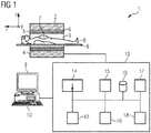
- FIG. 1 shows a schematic representation of a magnetic resonance imaging system 1 ("MRI-system").
- the MRI system 1 includes the actual magnetic resonance scanner (data acquisition unit) 2 with an examination space 3 or patient tunnel in which a patient or test person is positioned on a driven bed 8, in whose body the actual examination object is located.
- the magnetic resonance scanner 2 is typically equipped with a basic field magnet system 4, a gradient system 6 as well as an RF transmission antenna system 5 and an RF reception antenna system 7.
- the RF transmission antenna system 5 is a whole-body coil permanently installed in the magnetic resonance scanner 2, in contrast to which the RF reception antenna system 7 is formed as multiple local coils for parallel imaging (symbolized here by only a single local coil) to be arranged on the patient or test subject.
- the basic field magnet system 4 is designed in a typical manner so that it generates a basic magnetic field in the longitudinal direction of the patient, i.e. along the longitudinal axis of the magnetic resonance scanner 2 that proceeds in the z-direction.
- the gradient system 6 typically includes individually controllable gradient coils in order to be able to switch (activate) gradients in the x-direction, y-direction or z-direction independently of one another.
- the MRI system 1 shown here is a whole-body system with a patient tunnel into which a patient can be completely introduced.
- the invention can also be used at other MRI systems, for example with a laterally open, C-shaped housing, as well as in smaller magnetic resonance scanners in which only one body part can be positioned.
- the MRI system 1 has a central control device 13 that is used to control the MRI system 1.
- This central control device 13 includes a sequence control unit 14 for measurement sequence control.
- the sequence control unit 14 the series of radio-frequency pulses (RF pulses) and gradient pulses can be controlled depending on a selected pulse sequence or, respectively, a series of multiple pulse sequence to acquire magnetic resonance images of the patient O within a measurement session.
- RF pulses radio-frequency pulses
- gradient pulses can be controlled depending on a selected pulse sequence or, respectively, a series of multiple pulse sequence to acquire magnetic resonance images of the patient O within a measurement session.
- a series of pulse sequence can be predetermined within a measurement or control protocol.
- Different control protocols for different measurements or measurement sessions are typically stored in a memory 19 and can be selected by and operator (and possibly modified as necessary) and then be used to implement the measurement.
- the central control device 13 To output the individual RF pulses of a pulse sequence, the central control device 13 has a radio-frequency transmission device 15 that generates and amplifies the RF pulses and feeds them into the RF transmission antenna system 5 via a suitable interface (not shown in detail). To control the gradient coils of the gradient system 6, the control device 13 has a gradient system interface 16. The sequence control unit 14 communicates in a suitable manner with the radio-frequency transmission device 15 and the gradient system interface 16 to emit the pulse sequence.
- control device 13 has a radio-frequency reception device 17 (likewise communicating with the sequence control unit 14 in a suitable manner) in order to acquire magnetic resonance signals (i.e. raw data) for the individual measurements, which magnetic resonance signals are received in a coordinated manner from the RF reception antenna system 7 within the scope of the pulse sequence.
- radio-frequency reception device 17 likewise communicating with the sequence control unit 14 in a suitable manner
- magnetic resonance signals i.e. raw data
- a reconstruction unit 18 receives the acquired raw data and reconstructs magnetic resonance image data therefrom for the measurements. This reconstruction is typically performed on the basis of parameters that may be specified in the respective measurement or control protocol. For example, the image data can then be stored in a memory 19.
- Operation of the central control device 13 can take place via a terminal 10 with an input unit and a display unit 9, via which the entire MRI system 1 can thus also be operated by an operator.
- MR images can also be displayed at the display unit 9, and measurements can be planned and started by means of the input unit (possibly in combination with the display unit 9), and in particular suitable control protocols can be selected (and possibly modified) with suitable series of pulse sequence as explained above.
- the control device 13 comprises a system 12 designed to perform the method according to the invention.
- a preferred architecture of this system 12 is shown in the following figures. Its components preferably appear to be software modules.
- the MRI system 1 according to the invention, and in particular the control device 13, can have a number of additional components that are not shown in detail but are typically present at such systems, for example a network interface in order to connect the entire system with a network and be able to exchange raw data and/or image data or, respectively, parameter maps, but also additional data (for example patient-relevant data or control protocols).
- additional components for example a network interface in order to connect the entire system with a network and be able to exchange raw data and/or image data or, respectively, parameter maps, but also additional data (for example patient-relevant data or control protocols).
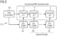
- FIG. 2 shows a preferred architecture of a system according to an embodiment of the invention.
- This architecture uses a deepsets coil sensitivity map estimation network CE (DS-CSME) and several deepsets coil sensitivity map refinement networks CR (DS-CSMR) that are explained in the following.
- CE deepsets coil sensitivity map estimation network CE
- DS-CSMR deepsets coil sensitivity map refinement networks CR
- the system is a trainable unrolled optimization framework with several cascades C of regularization networks and varying data consistency layers, CSMs are needed at each cascade C. Therefore, as shown in this figure, deepsets coil sensitivity map estimation and refinement networks CE, CR (DS-CSME and DS-CSMR in short) are used, enabling an integrated deep learning solution that enables end-to-end training for allowing for further MRI acceleration while preserving the overall reconstructed image quality.
- the proposed deepsets coil sensitivity map estimation network CE (DS-CSME) is used first to estimate CSM from the auto-calibration signal (ACS), while the proposed deepsets coil sensitivity map refinement network CR (DS-CSMR) is used to refine the estimated CSM after each reconstruction cascade if its usage was enabled.
- the acquired data of the coils is inputted from the data acquisition DA into the first cascade and the deepsets coil sensitivity map estimation network CE (DS-CSME). Then the data is further processed by the following cascades C and deepsets coil sensitivity map refinement networks CR (DS-CSMR). The weights the DS-CSMR CR is shared among the reconstruction cascades.
- the CSM estimation problem is naturally expressed as operating on sets of entities rather than vectors.
- the size X of the set i.e. the number of coils
- the proposed DS-CSME CE is restricted to a permutation invariant or equivariant functions (i.e. deepsets), which has a particular structure and can be decomposed for suitable transformations ⁇ and ⁇ for a coil x in the form of: ⁇ ⁇ x ⁇ X ⁇ x .
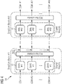
- FIG 3 shows a preferred architecture of a deepsets coil sensitivity map estimation network CE (the DS-CSME "block” in figure 2 ).
- the center k-space for each coil data is first extracted using a masking operator that zeros out all lines except for the ACS lines, which is followed by an inverse Fourier transform (IFT) to compute the corresponding coil images.
- IFT inverse Fourier transform
- the input set of coil images is then passed through deepsets blocks.
- Each deepset block is in this example composed of a novel Deep Iterative Hierarchical Network D (DIHN, explained in the following) applied for each coil image independently followed by a normalization of the estimated outputs using the root sum square (RSS) to ensure appropriate estimated CSMs.
- DIHN Deep Iterative Hierarchical Network D
- the normalization factor NF is then used to normalize each CSM separately resulting in N outputs, wherein DIHN #i of coil #j is set to DIHN #i of coil #j / NF.
- computed RSS can also be concatenated to the normalized outputs before applying the next deepsets block.
- Figure 4 shows a preferred architecture of a deepsets coil sensitivity map refinement network CR (the DS-CSMR "blocks" in figure 2 ).
- the proposed DS-CSMRs CR have a similar architecture to the proposed DS-CSME CE of figure 3 , but without the ACS masking and IFT operations.
- an image-to-image translation network is proposed, referred to as "Deep Iterative Hierarchical Network” (DIHN), with a hierarchical design that iteratively down-samples the input image feature maps followed by an up-sampling procedure, which is used as the primary building block of the proposed deepsets block.
- DIHN Deep Iterative Hierarchical Network
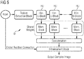
- Figure 5 shows a preferred architecture of a deep iterative hierarchical network D (the DIHN "blocks" of figures 3 and 4 ) .
- the proposed DIHN D is designed to ensure the system being fast and memory-efficient while also robust to variations in MRI intensities and contrasts (e.g. using different scanned organs, acquisition parameters, image resolutions, etc.).
- the input e.g. a complex image or a CSM
- the input is first passed through an initial feature extraction block where twice the input feature maps are extracted with half the image resolution achieved through convolutions with stride 2.
- the extracted features are then passed through several hierarchical U-blocks HU (explained in the following) that down-sample the input feature maps, allowing efficient processing at a coarser scale before up-sampling the processed feature maps using subpixel convolutions.
- a shared memory block (similar in construction to U-block but without the down-sampling and up-sampling operations) is used to process the extracted feature maps at different levels, then concatenating the memory block outputs before passing them to the final enhancement block.
- 1 ⁇ 1 convolution is used to fuse the concatenated representations followed by up-scaling using sub-pixel convolution to generate the final complex output image.
- Figure 6 shows a preferred architecture of a hierarchical U-block HU that is composed of a several U-blocks (explained in the following) that down-samples the input feature maps by convolutions with stride 2, allowing efficient processing at a coarser scale before up-sampling the processed feature maps using subpixel convolutions.
- the example of the hierarchical U-block HU shows three layers, wherein the dotted lines of the lowest layer indicate that there may be more layers of a similar architecture of the upper two layers.
- Figure 7 shows a preferred architecture of a U-block U used in the architecture of the hierarchical U-block HU.
- the sub-blocks of the U-block are symbols, with their meaning shown at the bottom of the figure.
- the first sub-block indicates a 3x3 convolution, a group normalization and a function PReLu, each a well-known procedure in the art.
- the second sub-block indicates a 3x3 convolution with the stride of 2, also a well-known procedure in the art, as well as the third sub-block indicating a 1x1 convolution and the fourth sub-block indicating a sub-pixel convolution with the scale of 2.
- the U-blocks design includes improved local and global residual connections to enhance information flow while maintaining efficient memory usage (compared to dense connections typically used).
- Group normalization is adopted instead of typically used batch normalization layers to better deal with high-dimensional medical imaging data. Additionally, PReLU activation is used to provide the network with additional modeling flexibility.
- transposed convolutions with a scale of 2 can also be used to increase the model flexibility additionally.
- Figure 8 shows a block diagram of the process flow of a preferred method for training a System 12 according to the invention.
- step I a plurality of multi-coil training datasets T is provided, each training dataset T comprising MRI-imaging data, especially under-sampled multi-coil k-space data, and a ground truth comprising fully-sampled multi-coil k-space data.
- step II the system 12 is trained with the training datasets T concerning the ground truth of each training dataset T.
Landscapes
- Physics & Mathematics (AREA)
- Engineering & Computer Science (AREA)
- Condensed Matter Physics & Semiconductors (AREA)
- General Physics & Mathematics (AREA)
- Radiology & Medical Imaging (AREA)
- Nuclear Medicine, Radiotherapy & Molecular Imaging (AREA)
- General Health & Medical Sciences (AREA)
- Health & Medical Sciences (AREA)
- Signal Processing (AREA)
- High Energy & Nuclear Physics (AREA)
- Artificial Intelligence (AREA)
- Computer Vision & Pattern Recognition (AREA)
- Magnetic Resonance Imaging Apparatus (AREA)
Priority Applications (2)
| Application Number | Priority Date | Filing Date | Title |
|---|---|---|---|
| EP21155573.5A EP4040180A1 (fr) | 2021-02-05 | 2021-02-05 | Système et procédé d'estimation de sensibilité et de reconstruction de bobines irm |
| US17/577,148 US11585876B2 (en) | 2021-02-05 | 2022-01-17 | System and method for MRI coil sensitivity estimation and reconstruction |
Applications Claiming Priority (1)
| Application Number | Priority Date | Filing Date | Title |
|---|---|---|---|
| EP21155573.5A EP4040180A1 (fr) | 2021-02-05 | 2021-02-05 | Système et procédé d'estimation de sensibilité et de reconstruction de bobines irm |
Publications (1)
| Publication Number | Publication Date |
|---|---|
| EP4040180A1 true EP4040180A1 (fr) | 2022-08-10 |
Family
ID=74556805
Family Applications (1)
| Application Number | Title | Priority Date | Filing Date |
|---|---|---|---|
| EP21155573.5A Withdrawn EP4040180A1 (fr) | 2021-02-05 | 2021-02-05 | Système et procédé d'estimation de sensibilité et de reconstruction de bobines irm |
Country Status (2)
| Country | Link |
|---|---|
| US (1) | US11585876B2 (fr) |
| EP (1) | EP4040180A1 (fr) |
Families Citing this family (4)
| Publication number | Priority date | Publication date | Assignee | Title |
|---|---|---|---|---|
| US20230122658A1 (en) * | 2021-10-18 | 2023-04-20 | Washington University | Self-supervised joint image reconstruction and coil sensitivity calibration in parallel mri without ground truth |
| KR102683611B1 (ko) * | 2021-11-22 | 2024-07-10 | 서울대학교 산학협력단 | Mri 이미지의 노이즈 제거를 위한 후처리 장치의 학습방법 및 이를 위한 컴퓨팅 장치 |
| US20240037815A1 (en) * | 2022-07-26 | 2024-02-01 | Siemens Healthcare Gmbh | Method and apparatus for accelerated acquisition and reconstruction of cine mri using a deep learning based convolutional neural network |
| CN115797483B (zh) * | 2022-08-29 | 2026-02-10 | 昆明理工大学 | 一种基于外积有效和字典学习的改进ESPIRiT重建方法 |
Citations (2)
| Publication number | Priority date | Publication date | Assignee | Title |
|---|---|---|---|---|
| US20200294282A1 (en) * | 2019-03-14 | 2020-09-17 | Hyperfine Research, Inc. | Deep learning techniques for alignment of magnetic resonance images |
| US20200300954A1 (en) * | 2019-03-22 | 2020-09-24 | Canon Medical Systems Corporation | Apparatus and method for deep learning to mitigate artifacts arising in simultaneous multi slice (sms) magnetic resonance imaging (mri) |
Family Cites Families (3)
| Publication number | Priority date | Publication date | Assignee | Title |
|---|---|---|---|---|
| DE102015203306A1 (de) * | 2015-02-24 | 2016-08-25 | Siemens Healthcare Gmbh | Verfahren zur Ermittlung von absoluten Empfangssensitivitätskarten für Empfangsspulen in einer Magnetresonanzeinrichtung und Magnetresonanzeinrichtung |
| CN107592912B (zh) * | 2015-05-13 | 2020-12-01 | 皇家飞利浦有限公司 | 利用rf线圈灵敏度映射的并行mr成像 |
| US10712416B1 (en) * | 2019-02-05 | 2020-07-14 | GE Precision Healthcare, LLC | Methods and systems for magnetic resonance image reconstruction using an extended sensitivity model and a deep neural network |
-
2021
- 2021-02-05 EP EP21155573.5A patent/EP4040180A1/fr not_active Withdrawn
-
2022
- 2022-01-17 US US17/577,148 patent/US11585876B2/en active Active
Patent Citations (2)
| Publication number | Priority date | Publication date | Assignee | Title |
|---|---|---|---|---|
| US20200294282A1 (en) * | 2019-03-14 | 2020-09-17 | Hyperfine Research, Inc. | Deep learning techniques for alignment of magnetic resonance images |
| US20200300954A1 (en) * | 2019-03-22 | 2020-09-24 | Canon Medical Systems Corporation | Apparatus and method for deep learning to mitigate artifacts arising in simultaneous multi slice (sms) magnetic resonance imaging (mri) |
Non-Patent Citations (4)
| Title |
|---|
| ANATOLE MOREAU ET AL.: "Deep transform networks for scalable learning of MR reconstruction", PROCEEDINGS OF THE INTERNATIONAL SOCIETY FOR MAGNETIC RESONANCE IN MEDICINE, ISMRM, 27TH ANNUAL MEETING AND EXHIBITION, MONTRÉAL, QUÉBEC, CANADA, 11 MAY - 16 MAY 2019, no. 4778, 26 April 2019 (2019-04-26), XP040712162 * |
| MAHMOUD MOSTAPHA ET AL: "Coil Sensitivity Estimation with Deep Sets Towards End-to-End Accelerated MRI Reconstruction", PROCEEDINGS OF THE 2021 ISMRM & SMRT ANNUAL MEETING & EXHIBITION, 15-20 MAY 2021, ISMRM, 2030 ADDISON STREET, 7TH FLOOR, BERKELEY, CA 94704 USA, no. 1166, 30 April 2021 (2021-04-30), XP040723185 * |
| MANZIL ZAHEER ET AL: "Deep Sets", ARXIV.ORG, CORNELL UNIVERSITY LIBRARY, 201 OLIN LIBRARY CORNELL UNIVERSITY ITHACA, NY 14853, 10 March 2017 (2017-03-10), XP081311878 * |
| MATTHEW J MUCKLEY ET AL: "State-of-the-art Machine Learning MRI Reconstruction in 2020: Results of the Second fastMRI Challenge", ARXIV.ORG, CORNELL UNIVERSITY LIBRARY, 201 OLIN LIBRARY CORNELL UNIVERSITY ITHACA, NY 14853, 9 December 2020 (2020-12-09), XP081835762 * |
Also Published As
| Publication number | Publication date |
|---|---|
| US20220252683A1 (en) | 2022-08-11 |
| US11585876B2 (en) | 2023-02-21 |
Similar Documents
| Publication | Publication Date | Title |
|---|---|---|
| US11585876B2 (en) | System and method for MRI coil sensitivity estimation and reconstruction | |
| US9396562B2 (en) | MRI reconstruction with incoherent sampling and redundant haar wavelets | |
| EP4266074A1 (fr) | Segmentation des images médicales reconstruites à partir d'un ensemble d'images de résonance magnétique | |
| US20240290011A1 (en) | Dual-domain self-supervised learning for accelerated non-cartesian magnetic resonance imaging reconstruction | |
| US9482732B2 (en) | MRI reconstruction with motion-dependent regularization | |
| EP3100067B1 (fr) | Irm à tranches multiples simultanées à codage de gradient aléatoire | |
| EP4088654A1 (fr) | Appareil et procédé de traitement d'image par résonance magnétique | |
| US11734817B2 (en) | Medical information processing apparatus, magnetic resonance imaging apparatus, and medical information processing method | |
| US20220260659A1 (en) | Medical information processing apparatus, magnetic resonance imaging apparatus, and medical information processing method | |
| CN115113114B (zh) | 用于带扩展视场线圈灵敏度校准的基于深度学习的加速磁共振成像的系统和方法 | |
| US20230044166A1 (en) | Accelerated time domain magnetic resonance spin tomography | |
| CN102654568A (zh) | 用来确定对于磁共振成像的激励参数的方法和装置 | |
| US12333677B2 (en) | Methods and systems for super-resolution with progressive sub-voxel up-sampling | |
| US12379440B2 (en) | Multichannel deep learning reconstruction of multiple repetitions | |
| KR20220082302A (ko) | 리스케일링과 인공신경망을 적용한 자기 공명 영상 처리 장치 및 그 방법 | |
| EP4095539B1 (fr) | Formation spécifique à la tâche d'un algorithme de réseau neuronal pour la reconstruction d'une imagerie par résonance magnétique et la détection d'objets | |
| US11119171B2 (en) | Systems and methods for adaptive multi-resolution magnetic resonance imaging | |
| EP4705961A2 (fr) | Reconstruction d'image pour imagerie par résonance magnétique | |
| JP6618786B2 (ja) | 磁気共鳴イメージング装置及び画像処理装置 | |
| EP4409313A1 (fr) | Conception d'impulsion radiofréquence à émission parallèle avec un apprentissage profond | |
| CN113567901A (zh) | 一种磁共振旋转坐标系下的自旋晶格弛豫成像方法和系统 | |
| US11815579B2 (en) | Magnetic resonance imaging apparatus and method | |
| CN115542216B (zh) | 同时多层成像的系统和方法 | |
| EP4312044A1 (fr) | Reconstruction d'imagerie par résonance magnétique basée sur des réseaux neuronaux | |
| KR102472546B1 (ko) | 노이즈 투 노이즈 기법이 적용되는 자기 공명 영상 처리 장치 및 그 방법 |
Legal Events
| Date | Code | Title | Description |
|---|---|---|---|
| PUAI | Public reference made under article 153(3) epc to a published international application that has entered the european phase |
Free format text: ORIGINAL CODE: 0009012 |
|
| STAA | Information on the status of an ep patent application or granted ep patent |
Free format text: STATUS: REQUEST FOR EXAMINATION WAS MADE |
|
| 17P | Request for examination filed |
Effective date: 20220111 |
|
| AK | Designated contracting states |
Kind code of ref document: A1 Designated state(s): AL AT BE BG CH CY CZ DE DK EE ES FI FR GB GR HR HU IE IS IT LI LT LU LV MC MK MT NL NO PL PT RO RS SE SI SK SM TR |
|
| STAA | Information on the status of an ep patent application or granted ep patent |
Free format text: STATUS: EXAMINATION IS IN PROGRESS |
|
| 17Q | First examination report despatched |
Effective date: 20230630 |
|
| RAP1 | Party data changed (applicant data changed or rights of an application transferred) |
Owner name: SIEMENS HEALTHINEERS AG |
|
| STAA | Information on the status of an ep patent application or granted ep patent |
Free format text: STATUS: THE APPLICATION IS DEEMED TO BE WITHDRAWN |
|
| 18D | Application deemed to be withdrawn |
Effective date: 20250611 |