EP4040202B1 - Reflexionsminderung am ende einer glasfaser in einem kleinen volumen - Google Patents
Reflexionsminderung am ende einer glasfaser in einem kleinen volumen Download PDFInfo
- Publication number
- EP4040202B1 EP4040202B1 EP22158300.8A EP22158300A EP4040202B1 EP 4040202 B1 EP4040202 B1 EP 4040202B1 EP 22158300 A EP22158300 A EP 22158300A EP 4040202 B1 EP4040202 B1 EP 4040202B1
- Authority
- EP
- European Patent Office
- Prior art keywords
- fiber
- light
- termination
- optical fiber
- coreless
- Prior art date
- Legal status (The legal status is an assumption and is not a legal conclusion. Google has not performed a legal analysis and makes no representation as to the accuracy of the status listed.)
- Active
Links
Images



Classifications
-
- G—PHYSICS
- G02—OPTICS
- G02B—OPTICAL ELEMENTS, SYSTEMS OR APPARATUS
- G02B6/00—Light guides; Structural details of arrangements comprising light guides and other optical elements, e.g. couplings
- G02B6/24—Coupling light guides
- G02B6/241—Light guide terminations
- G02B6/243—Light guide terminations as light absorbers
-
- G—PHYSICS
- G01—MEASURING; TESTING
- G01B—MEASURING LENGTH, THICKNESS OR SIMILAR LINEAR DIMENSIONS; MEASURING ANGLES; MEASURING AREAS; MEASURING IRREGULARITIES OF SURFACES OR CONTOURS
- G01B11/00—Measuring arrangements characterised by the use of optical techniques
- G01B11/16—Measuring arrangements characterised by the use of optical techniques for measuring the deformation in a solid, e.g. optical strain gauge
- G01B11/18—Measuring arrangements characterised by the use of optical techniques for measuring the deformation in a solid, e.g. optical strain gauge using photoelastic elements
Definitions
- the technology relates to optical fiber components, and more specifically, to the termination of optical fibers.
- the technology described below is particularly useful in interferometric measurements and optical fiber shape and/or position sensing applications.
- Optical strain sensing is a technology useful for measuring physical deformation of a waveguide caused by, for example, the change in tension, compression, or temperatuire of an optical fiber.
- a multi-core optical fiber is composed of several independent waveguides embedded within a single fiber.
- a continuous measure of strain along the length of a core can be derived by interpreting the optical response of the core using swept wavelength inteferometery.
- these independent strain signals may be combined to gain a measure of the strain profile applied to the multi- core optical fiber, in a technique known as optical position and/or shape sensing detailed in commonly-assigned U.S.
- optical fiber termination is the ratio of reflected light to the light incident on the termination.
- return loss ratio of reflected to incident power is a negative sign.
- the effective index of core light is typically about 1.46.
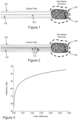
- the surface might be ill-defined in shape or of varying reflective properties, then the light emerging from the fiber must be carefully managed so that it is not reflected but instead converted to another form of energy, usually heat, in the allowed termination volume 104. In this way, the converted light energy is not reflected back into the fiber disrupting light intended to be carried in the fiber.
- many single-mode optical fiber sensors are made with an outside fiber glass diameter of 125 um and a protective polymer coating resulting in a total fiber diameter between 140 and 250 um.
- the small size and flexibility of such fibers is an advantage in applications where they are embedded inside small flexible structures and can be used to sense changes to within 5 mm of the end of the fiber.
- a desired return loss of an optical fiber termination might be on the order of the amount of light that would be back-reflected by the inherent scatter from 50 um of fiber. This means that less than 3 parts per billion of the original light may be permitted to be reflected back into the fiber core which translates into a return loss on the order of -85 dB-a return loss requirement among the lowest of any known application. More generally, for many fiber sensing applications with small volume termination requirements, a minimum return loss value of -70 dB can produce useful data depending on the application requirements.
- sensing is performed continuously from multiple cores embedded in the same fiber. Termination of such fibers poses further challenges because, unlike single core fibers, some of the cores are not centered in the fiber structure and are closer to the edge of the fiber. A core not centered in the structure poses a different challenge for termination than a core that is centered. Additionally, it is desirable to reduce the amount of light being reflected from one core back into any other cores, i.e., low cross coupling or "cross-talk" between cores at the termination may be required. Objectives for reducing cross-talk are similar to those for low return loss. Assuming the magnitude of light traveling in all cores is nearly equal, maintaining cross-talk below -70 dB, or below -85 dB for the more stringent applications is desirable.
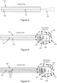
- FIG. 2 A fiber with multiple cores that requires a small volume termination is shown in Figure 2 , which employs the same numerical labels as in Figure 1 .
- the end of the fiber to be terminated might be attached to a fiber without a guiding core and with index of refraction matched to the effective core mode index of the fiber, a so-called "coreless" fiber.
- USP 5,263,103 describes that the index of refraction of the coreless fiber must nearly match the effective index of the fiber to be terminated.
- the length of the coreless fiber would need to exceed 3 cm in order to achieve -70 dB return loss. Even so, this approach does not ensure that the light does not escape the termination structure to be reflected by a nearby external surface.
- the reflection at the end of an optical fiber can be reduced by cleaving or polishing the end at a significant angle relative to the axis of an optical fiber.
- the quality of the angled surface is critical to the return loss achieved.
- some of the light incident on the angled surface is still transmitted through the angled surface and some is reflected at an angle. If a reflective surface is brought in near proximity to the angled end, substantial reflection back into the fiber core may occur. If the light is allowed to expand into a large volume, it can eventually be absorbed to provide a low return loss. But as mentioned above, large termination volumes are not practical or desirable in many applications.
- An anti-reflection coating could be applied to the surface of the fiber either as a stack of different optical index layers or an absorbing material such as carbon-black. But the diffuse reflection from carbon-black or from layered coatings is significant. In fact, any known material that is close to the termination which has primarily diffuse reflection does not achieve the low return loss needed for these demanding applications. If a material is to be placed close to the fiber, then it either needs to be a highly-absorbing, low-scatter, volume-absorber, or it needs to have a highly specular reflection and be arranged in a geometry such that multiple specular reflections, with high absorption, occur before the light finds its way back to the fiber, either into the core from which it was emitted, or into another core of the fiber.
- USP 6,496,643 describes using an absorptive material in a termination but requires it to be contained in the core of a fiber with a mode effective index matched to the effective index of the fiber to be terminated. Another issue with an absorber confined to the core of a termination is that it is not readily applicable to multiple cores. Furthermore, this approach leaves light in a small core at the end of the termination structure, thus not benefiting from the expansion of the beam into larger area.
- any material attached to absorb light at a fiber termination must be index-matched, either as a bulk material in a coreless fiber or by matching a mode in a guiding structure.
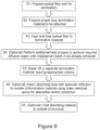
- Figure 3 plots a theoretical reflection at a boundary as a function of index difference for a standard silica fiber directly coupled to such material. Direct attachment of any material to such a fiber would result in too high a return loss to meet the desired requirements described above unless the material index of refraction difference was less than about 0.001. The chance of finding a material in such a narrow index range which absorbs strongly enough to absorb a large portion of light within a few mm distance is very small. Many materials are highly absorbing but highly scattering or are not available in a form that is index matched to optical fiber. For example, metal particles embedded in almost any material are both highly scattering and highly absorbing for optical wavelengths. Such materials exist but produce a very high reflection when placed at the end of a fiber.
- the present invention provides a device and a method of terminating an optical fiber as defined in the appended independent claims.
- Optional features are defined in the appended dependent claims.
- An optical fiber termination provided at an end of an optical fiber including one or more cores includes a structure having a volume including an absorptive region of absorptive material provided to the end of the optical fiber that absorbs light emitted from each of the one or more cores to reduce reflections into the one or more cores to a return loss of -70 dB or less regardless of the presence of surfaces proximate the optical fiber termination.
- a length of the structure is less than 5 mm, and a largest transverse dimension of the structure is less than 325 um.
- the structure has cylindrical symmetry, the volume is greater than 0.001 mm3 and less than 0.415 mm3 , a length of 3 mm or less, and a radius of 100 ⁇ m or less.
- the optical fiber termination structure includes a diffusion region formed from heating the end of the optical fiber together with a proximal portion of the absorptive region abutting the end of the optical fiber.
- the optical fiber is associated with a first index of refraction
- the absorptive region is associated with a second index of refraction.
- the diffusion region gradually transitions between the first index of refraction and the second index of refraction. If there is a mismatch between the first index of refraction and the second index of refraction, the diffusion region gradually transitions between the first index of refraction and the second index of refraction to reduce reflections that occur from the mismatch.
- the absorptive material absorbs light emitted from the one or more cores so that any light escaping the absorptive region and reflected by an exterior surface into the one or more cores results in a return loss less than -70 dB.
- the absorptive material is borosilicate glass, cobalt-doped blue borosilicate glass, or chromium-doped glass.
- the absorptive region includes a light-absorptive tube.
- the light-absorptive tube is metal, and material of the absorptive region includes a coreless optical fiber at least partially encompassed by the light-absorptive tube.
- the coreless optical fiber diffuses at a proximal end with the end of the optical fiber, and the coreless optical fiber tapers at a distal end away from the end of the optical fiber. It may be desirable to fill the light-absorptive tube epoxy along with the coreless optical fiber for mechanical reasons and/or for the epoxy to absorb light.
- the optical fiber may include multiple cores, and in that case, the structure reduces cross-coupling between terminations of the multiple cores to less than -70 dB. Moreover, one or more cores may be off-center in the fiber structure..
- the optical fiber termination described achieves an exceptionally low return loss termination in a small volume.
- a first characteristic for achieving this objective is the use of a material within an allowed, small termination volume of the optical fiber termination that is highly absorbing at the optical wavelength of interest, so that light is converted to some other form of energy, usually heat, within the termination volume.
- a second characteristic is that the index of refraction at the interface between the termination and the fiber end is configured to provide a gradual conversion of light to a large region without reflection in proximity to the core, where scattered light could couple back into the fiber.
- a third characteristic is that the absorbing material interacts with the light without substantial reflection back in the direction of the fiber while adequately reducing light emitted outside the termination volume. Different embodiments may employ all or less than all of these characteristics.
- silica-based glass doped with certain materials such as cobalt or chromium can have desirable absorption and scattering properties, but do not match the index of refraction of the fiber to be terminated, and often produce high levels of scattering when the dopant level is high enough to absorb many dBs of light within a few millimeters.
- a 10 dB/cm absorption is possible in such glasses in silica cores, but this is not high enough for many small volume termination applications.
- Other glass compositions that support higher levels of absorbing dopant unfortunately have substantially different indexes of refraction.
- the mismatch between two materials can be sufficiently reduced by thermally heating the interface to a high enough temperature so that the components of the fiber to be terminated and the absorbing termination material diffuse into each other.
- Metals in crystalline form are effective absorbers of optical wavelengths of light, and light does not pass through even extremely thin metal layers.
- metals are also effective reflectors. So a solid metal surface or metal particles embedded within another material, such as an epoxy, placed at the end of a fiber absorb substantial incident light but also produces very high levels of reflected light. Depending on the angle of incidence, the light can return back to the fiber core or can be multiply reflected to eventually partially return to the fiber core. If the fiber has multiple cores, the challenge of preventing light from returning to any of the cores is increased.
- Figure 4 depicts light expanding from the end of a single mode single core fiber at 107. If a surface of metal is parallel to the direction of propagation of the light, the light can interact with the metal surface gradually as the optical beam diverges.
- a metal tube is placed over the end of the fiber to mechanically protect the end of the fiber.
- the surface of the metal tube or other metal termination structure shape does not need to be parallel to the direction of propagation of the light. Rather, the orientation of the optical fiber in the termination may be manipulated to cause the light to interact with the metal surface over a shorter length such that the back reflection remains small while substantially all the light is absorbed by the metal within a short distance in the light propagation direction. The rate at which such a metal surface can absorb light from an expanding optical beam while keeping the reflected light to a low level dictates how a small termination volume can be achieved.
- the features implemented for creating a small volume optical fiber termination capable of being placed in immediate proximity to another reflecting surface is shown in Figure 5 for a single-core fiber and in Figure 6 for a multi-core fiber.
- the optical fiber termination volume need not be any particular shape, e.g., cylindrical, or have a particular symmetry.
- Light emerging from the optical fiber passes through a diffusion/transition region 201 in which the fiber core(s) expands laterally, and the index of refraction gradually transitions from the/each core's index to the index of material in the absorption region 202 of the optical fiber termination.
- the absorbing material is depicted as occupying the entire allowed termination volume 104.
- the distribution of absorption is not critical as long as the magnitude is adequate, and the remaining light is controlled so that a substantial quantity does not cross the boundary from the allowed termination volume 104 to hit the next surface 105 or to reflect substantially back towards the core, as indicated by the crossed out arrows 203.
- the example structures in Figures 5 and 6 include a diffusion/transition region 201 that allows light to expand from the core(s) of the fiber into the termination volume 104that includes an absorbing region 202 to absorb the wavelength of interest and convert the light to heat or another form.
- the absorbing region 202 preferably contains an absorbing material. The absorbing material need not be uniformly distributed within the absorption region 202 as long as the amount of light that escapes or is reflected back to the cores is controlled.
- These structures prevent or at least largely prevent scattered light from propagating back into the cores or out of the termination volume 104.
- the diffusion/transition region 201 may achieve different degrees of matching between dissimilar materials depending upon the amount and type of processing performed, the initial mismatch, and the requirements of the application (processing may stop when an adequate match is achieved).
- a greater scattering back into the core from the absorption region may be allowed in order to utilize a doped material that absorbs more light rapidly, thus making the device smaller at the expense of performance.
- Greater escaped light may also be allowed to make the device smaller if the characteristics of the next surface to be encountered are known or can be controlled.
- the crossed-out arrows in the figures do not mean that absolutely no light passes that direction, only that the light is managed to the level required by the application.
- the termination structure 302 includes an absorbing material occupying at least a majority of the full termination volume and is directly attached to the end of the fiber to be terminated by heat processing at the end of the fiber interface.
- the absorbing material is chosen to be adequately absorbing to convert the majority of light to heat in a small volume but with minimal scattering. Additionally, careful thermal treatment in the diffusion region 301 ensures that reflections that would otherwise result from index mismatch are prevented or at least substantially prevented. Both ends of the termination structure 302 are depicted as being somewhat rounded because this is generally the natural result of using thermal processes.
- Processes that cause diffusion at the fiber/termination boundary typically produce a smoothing rounding effect between the materials. Many processes can be used to produce the far boundary of the structure. For the example in Figure 6 , the termination is heated and pulled off, creating the rounded effect shown. However, the termination may also be cut, polished, cleaved, crushed, snapped, or broken in other ways that may produce acceptable results.
- Figures 7 and 8 show a largest transverse dimension corresponding to the diameter of those cylindrical structures. But other shape structures are possible that lead to a different termination volume and shape. Nevertheless, every structure includes some sort of length and largest transverse dimension.
- diameter is used in the examples below, the technology is applicable to any termination shape regardless of whether it has a diameter dimension.
- a second non-limiting example embodiment of a termination structure that achieves the three characteristics described above is shown in Figure 8 .
- a material with index of refraction similar to the index of the core to be terminated 402 is used inside the termination volume and is tapered 405 some distance from the expanded fiber core in the diffusion/transition region 401.
- the termination may use an undoped silica fiber to allow the light to expand and an index-matched epoxy or other material once expanded at the end of the undoped silica fiber 406.
- Light absorption is produced by interaction at a grazing angle 499 shown in an expanded view at Figure 8A with a light-absorbing tube 404 suitably prepared on the inside surface of the tube to prevent significant diffuse reflection toward the fiber core 101.
- Preparation of the inside of the tube can include a wide variety of commonly practiced manufacturing techniques including but not limited to cleaning, deburring, and polishing and such preparation might not be a separate processing step. In some cases an as-made tube will have acceptable performance without additional processes.
- the tube 404 may be made of metal and may also be filled with an index-matched epoxy 403 that allows for propagation to the end of the metal tube. Some light-absorption may also be produced by selecting a matching material, possibly an epoxy, with some level of light-absorption. Other various implementations of this example embodiment that allow light to expand into a coreless material and then interact with metal or other specular reflecting material at a grazing angle are also possible. As defined here, a grazing angle has an angle of incidence between the light and the surface normally greater than 45 degrees, and more preferably greater than 75 degrees. The grazing angle needed to achieve acceptable reflections depends on the amount and direction of diffuse reflections from the tube surface.
- the taper 405 may be made with coreless fiber in order to efficiently launch light from the core(s) into the termination volume without producing any scattering events close to the end of the core(s). It is beneficial if the termination media 403 is nonscattering, has an index of refraction close to but slightly above the index of refraction of the taper 405 material, and adheres the coreless material 402 to the light-absorbing tube 404.
- the termination material index of refraction should be close enough to the taper 405 index of refraction so that the reflection from the interface between the taper and the termination media, when coupled back into any core, is below the desired target return loss and allowed cross coupling magnitude. For example, commercially available optically transparent epoxies are suitable for the termination media.
- the termination media may be light-absorptive, this is not necessary if the termination region is bounded at least in part by a light-absorbing tube 404.
- the light-absorbing tube 404 geometry reduces scattering back into the core(s), because most scattered photons will propagate forward, while also providing a high degree of light-absorption.
- Commercially available hypodermic needle stainless steel tubing is an example of a readily available and suitable material for a light-absorbing tube 404.
- the light-absorbing tube 404 combined with the taper 405 and termination media 403 form a highly light attenuating, multi-mode waveguide.
- non-limiting example fiber termination structure embodiments shown in Figures 7 and 8 and variations thereof might be made by a non-limiting, example process described by the flow diagram of Figure 9 .
- the illustrated order of operations is a preferred order, other orders may be used, e.g., as new materials and processing methods become available.
- Step S1 Prepare the fiber optic end for termination by removing some coating, cleaning off residue, and cleaving the end. Cleaving the end at a 15 degree angle, for example, can improve the final result, but a flat (0 degree) cleave produces acceptable results for many applications.
- Step S2 Prepare proper size termination, e.g., by pulling light-absorptive glass down to a diameter on the order of the diameter of the fiber optic to be terminated.
- Step S3 Place the prepared optical fiber end and a proximal end of the light-absorptive material, e.g., glass, into a fusion splicer, bring them into proximity. Position the interface between the optical fiber end and the termination's light-absorptive material such that the fiber end is exposed to a higher temperature than the absorptive material, and fuse together by heating, e.g., with a high power arc.
- the light-absorptive material e.g., glass
- Step S4 Optical measurements at this point may well show that the two materials are physically connected but the reflection from the interface might be too large. Perform additional heating to achieve desired/required diffusion region with impedance match and to achieve an acceptable reflection loss (if not already achieved), e.g., with a high power arc. It may be necessary to move the fiber and the absorptive material together to prevent the interface from separating Step S5: Break off, separate, form, mold, etc. termination material to produce the desired length and/or volume for termination structure.
- One way to separate the termination absorptive material from the rest of the material so that an appropriate length of the absorptive material is attached to the optical fiber is to reposition the fiber in the splicer, fire an arc, and pull the two ends of the structure apart such that the glass stretches and then breaks at the point where it is heated. It may be necessary to repeat the pull-off step several times to separate the glass. It may also be necessary to reposition the structure between arcs to achieve an optimal taper. It can be beneficial to separate the termination material in such a way that the end has a prescribed geometry, e.g., a taper.
- Step S6 Place a tube over the termination material attached in steps 1-4. Attach the tube to the termination material with adhesive, e.g., index matching epoxy.
- the tube can be added to provide benefit in absorbing light or for mechanical protection.
- the step of adding of a tube for the second example embodiment in Figure 8 is not required for the first example embodiment as depicted in Figure 7 .
- Step S7 Add a light-absorbing material to the surface of the termination structure.
- the material might be added to the entire surface of the structure or just added to particular regions, e.g. the end only. This can be particularly useful when the termination structure is expected to be used in close proximity to a reflective surface, but it is not required if an adequate result is achieved without such material.
- the process above was performed to terminate a test silica fiber with 7 single-mode germanium cores arranged with 6 cores around 1 centered core with a core-to-core spacing of 35 um. Only 4 of the cores, 3 symmetrically arranged around the center core, were used in the example test.
- the test fiber had an outside glass diameter of 125 um and was terminated using different absorbing materials.
- the first absorbing material was Blue Vycor ® 7904, with a composition of 96% SiO 2 , 3% B 2 O 3 and 1% being a mixture of Na 2 O, Al 2 O 3 , ZrO 2 , and CoO.
- the concentration of CoO is estimated to be less than 0.1%.
- Blue Vycor The index of refraction of Blue Vycor is well-matched to the effective index of refraction of the optical fiber's guided mode. This absorbing material was successfully fused to the fiber and produced acceptable interface reflection results but required a length in excess of 1 cm to achieve acceptable return loss for the termination. Blue Vycor was measured to have an absorption of 1.4 dB per mm for light with a wavelength of 1550 nm. It was found that a cobalt-doped blue borosilicate glass with composition approximately [0-45%, Na- 3%, Al-2%, Si-35%, B-13%,Co-2%] had a significantly higher absorbance, on the order of 13 dB per mm.
- the index of refraction of the borosilicate glass is significantly different than the effective index experienced by the guided light in the fiber core. It was found that the reflection at the material interface could be reduced by heating the interface for a sufficient length of time to a sufficient temperature. If the heating is done with a plasma arc, the temperature is typically not known. In this case, the interface is heated until interface reflections are acceptable, as observed using an appropriate optical measurement tool. The heating process can be done as one continuous step or as a series of shorter steps with intervening measurements to produce better process control.
- Ten terminations were made using the above described process with the borosilicate glass, the fibers being angle-cleaved before fusing, and all terminations being heat processed multiple times to achieve an acceptable reflection at the fiber to absorptive glass interface. All terminations, once separated, measured less than 3 mm in length beyond the initial fiber end with an outer diameter less than 190 microns with a total termination volume approximately 0.085 mm 3 . In an example not according to the claimed invention, no metal tube was added to these terminations (Step 6 was not performed). The reflection of 4 of the cores was measured for all ten terminations. All terminations had reflections measured at less than -70 dB return loss. Terminations can be produced which have reflections less than -85dB by skilled operators and carefully following the procedures described.
- the following calculation is helpful in estimating the required absorption of the material used in the termination for this approach. Assuming that light from the fiber core expands smoothly through the diffusion region with little reflection, and expands to fill the structure, it is important that the light be absorbed rapidly enough to avoid other reflections, particularly reflections from the boundary of the termination to an air interface or from any reflection beyond the structure. The main such reflection is typically from the far end of the structure and such light passes twice through the absorbing material.
- a core is the area of the core mode of the fiber
- a clad is the area of the fiber cladding
- R end ( dB ) is the reflection coefficient of the end of the structure
- ⁇ is the absorption per unit length in dB/mm of the absorbing material
- l is the length of the absorbing material in mm.
- This equation assumes the light expands into the area of the cladding, and so the light coupled to the core after reflecting from the far end is reduced approximately by the ratio of the areas of the core to the cladding, by the absorption produced by passing twice through the absorbing region, and by the magnitude of the direct reflection at the end. So there are three ways to reduce the measured reflection: 1) absorb the light on the round trip pass from the core to the most distal surface and back to the core, 2) reduce the amount of light reflected from the most distal surface, and 3) make sure the reflection from the most distal surface does not reflect directly back into the core. The assumption is that the light has successfully left the core without a large reflection at the core-to-material interface.
- the loss of 2 passes through the termination material would need to be 33 dB to achieve a -70 dB reflection. If this is to be achieved in 2 passes through a 2 mm length in this example, then the termination material absorption is preferably at least 8.25 dB/mm.
- the maximum length and largest transverse direction (e.g., outer diameter) of the termination structure are limited by the requirements to fit inside an external structure of small size and to sense within a certain length of the physical end. These limits are set at 5 mm length and 325 um by practical application.
- the greatest outer diameter of the termination is measured by measuring the largest transverse dimension of the termination structure.
- the termination structures described above for this first example embodiment are all substantially smaller than these upper limits. Increasing the size of the termination structure does not diminish the optical performance, and therefore, any larger termination may be used.
- the minimum length is set as described above by the absorption rate achieved by the absorbing material. In example tests, 2 mm termination lengths have been achieved.
- the minimum largest transverse dimension of the termination structure is limited by the requirement to couple light from all cores of interest into the termination structure and then achieve the desired return loss.
- all cores must be enclosed by the diffusion region of the termination, so this is one practical minimum.
- the outer extent of the cores is 70 um.
- the termination must be larger than the core, which is typically only a few microns in size.
- the minimum largest transverse dimension is limited by the inverse relationship between beam divergence and the magnitude of light reflected into an optical core, represented by the cladding to core area ratio described above.
- the smallest volume terminations built by the inventors to date using the technology in this application is method have a 2 mm length, less than a 190 um maximum transverse dimension, and an overall volume approximately 0.0567 mm 3 .
- the inventors believe the minimum achievable volume using the technology in this application may approach 0.001 mm 3 by using rapid absorption and smaller diameter material.
- Figure 10 is a graph of the reflection as a function of position at the end of a test fiber with a 2 mm long termination.
- the data was measured using a Luna OBR, and the value on the Y axis represents the power reflected per spatial resolution of the system, which is 40 um in this example.
- An integral of this graph over the length of the termination structure, scaled for the number of points and resolution, is the return loss of the termination.
- 5 indicates the noise floor of the measurement
- 1 indicates the scattering that is inherent in the fiber
- 2 indicates a small increase in reflection over the intrinsic scatter that occurs at the transition region
- 3 indicates the very small value that is measured for reflection in the absorptive material which is indistinguishable from the noise floor of the measurement
- 4 indicates the reflection from the interface between the distal surface of the termination structure and air.
- the reflection loss at 4 is above the reflection loss indicated at 1, but these reflection loss values may be acceptable for most applications.
- Figure 11 is a graph of the reflection at the end of a fiber with a 2.5 mm long termination. Similar label numerals are used as for Figure 10 .
- the measurement in Figure 11 indicates that the absorption of the glass absorptive material in the termination attenuates the light enough that the end of the termination is no longer able to scatter substantial light into the core. Comparing the peak indicated by number 4 in both Figures 10 and 11 a termination measured in Figure 11 produces a reflection from the most distal surface that is indistinguishable from the measurement noise at 5, while the termination measured in Figure 10 produces a reflection from the most distal surface at 4 that is larger than the fiber scatter at 1. This shows that a termination longer than 2 mm is needed if it is required to have a reflection below fiber scatter and this particular material is used.
- the second example embodiment may also be produced by a process as summarized by Figure 9 .
- the following example procedure may be used for terminating an optical fiber in a small space with very low back reflection at the termination in accordance with the termination structure depicted in Figure 8 .
- Those skilled in the art of optical splicing understand that variations of the procedure will also produce acceptable results.
- the procedure was carried out on a Fujikura FSM-40PM Arc Fusion Splicer with firmware version 2.0.7 controlled by Splicelab software version 2.0.7.
- the procedure is summarized as follows with an example result at steps 2, 5, and 6 being depicted in Figure 12 .
- Step S1 Prepare the fiber optic end for termination by removing some coating and cleaving the end. Cleaving the end at an angle, for example, can improve the final result, but a flat (0 degree) cleave produces acceptable results for many applications.
- Step S2 Prepare proper size termination material by stripping coating and cleaning coreless fiber material.
- Step S3-S5 Place the prepared optical fiber end and a proximal end of the light-absorptive material, e.g., glass, into a fusion splicer, bring them into proximity. Position the interface between the optical fiber end and the termination's material such that the termination material is exposed to a higher temperature than the fiber end, and fuse together by heating, e.g., with a high power arc. At the end of the heating arc, move the materials apart, such that the termination material excess is separated from the fiber.
- These 3 steps may be separated to allow control of the quality of the diffusion and separation processes independent of the fusion process (as in embodiment 1). But these were not separated in the example test implementation described.
- Step S6 Remove terminated fiber from the splicer and position a clean metal tube (for the second example embodiment) over the terminated end pushed against the end of the optical fiber coating. Wick epoxy that is closely index-matched to the coreless fiber into the metal tube and thermally cure for several hours. Clean off excess cured epoxy from end of tube and from the point of attachment with fiber-optic and coating. Add more epoxy inside the metal tube if desired for mechanical reasons.
- Step S7 Another optional step is to add light-absorbing material to the outside of the termination structure.
- the material is advantageously added only to the most distal end because light does not escape through the metal tube.
- This process was performed for an example 125 um fiber with 7 single-mode cores, each with numerical aperture 0.21 located as 6 cores around 1 central core with 35 um core to core spacing and with an acrylate coating diameter approximately 200 um.
- the metal tube used was a 34 gauge, ultra thin wall (34UTW) stainless steel tube 3 mm long with 128 um inside diameter and outside diameter approximately 195 um , smaller than the coating material.
- the tip of the terminated fiber optic was generally located about 1 mm from the tube end, allowing about 1 mm of epoxy in the tube.
- the Epoxy used was Epo-Tek 301 A+B 2-part epoxy.
- the coreless fiber used was OFS part # 552 HPWR040.
- Termination RL of 3 outer cores (dB) RL of center core (dB) T071 -88.9,-83.3,-79.6 -73.2 T072 -74.7,-80.3,-72.8 -73.0 T073 -74.9,-77.5,-75.4 -73.6
- the grazing angle metal tube used in the test did not achieve as much absorption as the borosilicate glass used in the test.
- the light expands from the fiber core such that it must propagate about 0.6 mm before it reaches the metal tube boundary.
- the epoxy serves as the absorber in this structure, a search for index matched epoxy absorbing at the required rate but not scattering back into the core proved unsuccessful.
- the epoxy absorption in this non-limiting test case is minimal. So, unlike the approach with a volume absorber placed intimately in contact with the optical waveguide, a lower limit to how short the termination is partly determined by the size of the tube and the rate of light beam expansion produced by diffraction as shown in Figure 4 at 107.
- the metal tube is larger in diameter, then it would be less effective in a shorter length. If the metal tube is substantially smaller, then it would directly reflect light into the outer cores. However, for some applications, a return loss of -70 dB is adequate, and a metal protective tube is advantageous for protecting the structure.
- the same approach was used, in an example not according to the claimed invention, with a glass tube rather than a metal tube.
- the return loss in this case was generally less than -60 dB. But it was observed that dirt or a nearby surface outside the glass tube or at its end increased the reflection into the core and the return loss.
- the inventors discovered that devices made using a larger metal tube than that described above produce return loss values typically higher, between -60 and -70 dB, especially for the central core. Unexpectedly, the inventors found that making the metal tube smaller increases the light interaction with the metal, and as a result, the smaller volume device produces better return loss with the added benefit of a smaller termination volume.
- the maximum length and maximum transverse dimension of the termination structure were set by the example, non-limiting application requirements to be 5 mm and 325 um respectively, but the termination structures actually made were much smaller, occupying only approximately 0.0895 mm 3 .
- the minimum length and transverse dimension values are set depending on the return loss on metal absorption rate, beam divergence, and end reflection.
- the termination structure must be big enough to contain a diffused region for the entire set of fiber cores, but in this example embodiment, the metal tube size may also be limited by practical constraints, like how small and thin wall a substantially cylindrical metal tube can be made and processed.
- the metal tube placed over the end of the structure may be added by a different process or it may be formed in place. That is, metal might be deposited, sputtered, melted on, or added on the outside surfaces of the termination structure after the glass is processed. Deposited metal material still constitutes a metal absorbing tube at a grazing angle and may also conform to a taper and therefore be tapered itself while still providing a grazing angle absorber in the absorption region.
- the addition of a metal tube in this way means that steps S6 and S7 from the above described process would be combined.
- a single heat process with a flat cleaved fiber end formed an adequate diffusion region to produce a low reflection.
- the diffusion region is an important characteristic in this example embodiment. Calculations made by the inventors predicted that a direct contact between this test optical fiber (measured effective mode index 1.4782) and the termination material (index 1.448) without any diffusion would produce a return loss of -39 dB. But a Luna OBR measurement shows that the reflection at the fiber-termination interface is generally less than -80 dB using a single heat process. At this level, the reflections from the glass-to-epoxy interface and from the epoxy-to-air interface generally dominate the overall return loss.
- a metal tube may be added to the termination structure as in the second example embodiment in Figure 8 .
- the two example embodiments may be merged together as well as manufactured using a single process with improved performance.
- Another example embodiment coats the surface of the absorptive glass with a light absorbing coating, for example, carbon black or black rubber.
- Loctite 380 with Black Max ® was tested as an example. With Black Max ® applied directly to the end of an optical fiber, back reflections too large for the required return loss were observed. However, applying Black Max ® to the outer surface of the absorptive glass that is approximately 2 mm long helps eliminate light without increasing reflections. Adding the same Black Max ® material to the end of the optical fiber termination was found to reduce the residual reflection for this embodiment as well.
- While light-absorptive glass is referred to in the first example embodiment, other dielectric materials may be used which have suitable light absorption properties and can achieved the desired attachment properties. Although stainless steel works well as a light-absorbing metal tube in the second example embodiment, other light-absorbing metals can be used. In addition, the index-matching epoxy may be chosen to meet the requirements of a particular application.
Landscapes
- Physics & Mathematics (AREA)
- General Physics & Mathematics (AREA)
- Optics & Photonics (AREA)
- Optical Fibers, Optical Fiber Cores, And Optical Fiber Bundles (AREA)
Claims (10)
- Vorrichtung, die Folgendes umfasst:einen Lichtwellenleiter mit einem oder mehreren Kernen (101);eine kernlose Faser (402), die an einem distalen Ende des Lichtwellenleiters an den Lichtwellenleiter fusioniert ist, wobei die kernlose Faser (402) an einem distalen Ende der kernlosen Faser (402) eine Verjüngung (405) bildet; undeine lichtabsorbierende Metallröhre (404), die einen distalen Abschnitt des Lichtwellenleiters umgibt, an der kernlosen Faser (402) haftet und sie umgibt und sich distal über die Verjüngung (405) hinaus erstreckt, wobei die lichtabsorbierende Metallröhre (404) eine hohe spiegelnde und eine geringe diffuse Reflexion erzeugt, wenn Licht unter einem streifenden Einfallswinkel auf die lichtabsorbierende Röhre einfällt;wobei eine Diffusionsregion (201, 401) durch Erhitzen des distalen Abschnitts des Lichtwellenleiters zusammen mit einem proximalen Abschnitt der kernlosen Faser (402) gebildet wird,wobei sich die ein oder mehreren Kerne (101) lateral innerhalb der Diffusionsregion (201, 401) ausdehnen, um zu bewirken, dass sich Licht vom Lichtwellenleiter in der kernlosen Faser (402) ausdehnt und mit der lichtabsorbierenden Metallröhre (404) unter einem streifenden Einfallswinkel von mehr als 45 Grad in Wechselwirkung tritt,wobei der distale Abschnitt des Lichtwellenleiters, die kernlose Faser (402) und die lichtabsorbierende Metallröhre (404) gemeinsam eine Abschlussstruktur bilden, die den Lichtwellenleiter abschließt, undwobei die Abschlussstruktur eine Länge von weniger als 5 mm und eine größte Querabmessung von weniger als 325 µm aufweist und eine Rückflussdämpfung von -70 dB oder weniger unabhängig vom Vorhandensein von Oberflächen (105) in der Nähe der Abschlussstruktur erreicht.
- Vorrichtung nach Anspruch 1, wobei der Lichtwellenleiter einen Lichtwellenleiter auf Siliziumdioxidbasis umfasst und wobei die kernlose Faser (402) eine undotierte Siliziumdioxidfaser umfasst.
- Vorrichtung nach Anspruch 1, die ferner ein Abschlussmedium (403) zwischen der lichtabsorbierenden Metallröhre (404) und der Verjüngung (405) umfasst.
- Vorrichtung nach Anspruch 3, wobei das Abschlussmedium (403) einen Brechungsindex nahe und über einem Brechungsindex der Verjüngung (405) aufweist.
- Vorrichtung nach Anspruch 3 oder 4, wobei das Abschlussmedium (403) die kernlose Faser (402) an die lichtabsorbierende Metallröhre (404) heftet.
- Vorrichtung nach einem der Ansprüche 3 bis 5, wobei das Abschlussmedium (403) nichtstreuend ist.
- Vorrichtung nach einem der Ansprüche 3 bis 6, wobei das Abschlussmedium (403) lichtabsorbierend ist.
- Verfahren zum Abschließen eines Lichtwellenleiters mit einem oder mehreren Kernen (101), wobei das Verfahren Folgendes umfasst:Fusionsspleißen einer kernlosen Faser (402) an den Lichtwellenleiter an einem distalen Ende des Lichtwellenleiters, wobei die kernlose Faser (402) an einem distalen Ende der kernlosen Faser (402) eine Verjüngung (405) bildet;Erhitzen eines distalen Abschnitts des Lichtwellenleiters zusammen mit einem proximalen Abschnitt der kernlosen Faser (402), um eine Diffusionsregion (201, 401) zu bilden, in der sich die ein oder mehreren Kerne (401) lateral ausdehnen; undUmgeben des distalen Abschnitts des Lichtwellenleiters und der kernlosen Faser (402) mit einer lichtabsorbierenden Metallröhre (404) und Heften der lichtabsorbierenden Röhre (404) an die kernlose Faser (402), wobei sich die lichtabsorbierende Röhre (404) distal über die Verjüngung (405) hinaus erstreckt und eine hohe spiegelnde und eine geringe diffuse Reflexion erzeugt, wenn Licht unter einem streifenden Einfallswinkel auf die lichtabsorbierende Metallröhre (404) einfällt,wobei die laterale Ausdehnung der ein oder mehreren Kerne (401) bewirkt, dass sich das Licht von dem Lichtwellenleiter in die kernlose Faser (402) ausdehnt und mit der lichtabsorbierenden Metallröhre (404) bei einem streifenden Einfallswinkel von mehr als 45 Grad in Wechselwirkung tritt,wobei der distale Abschnitt des Lichtwellenleiters, die kernlose Faser (402) und die lichtabsorbierende Metallröhre (404) gemeinsam eine Abschlussstruktur bilden, die den Lichtwellenleiter abschließt, undwobei die Abschlussstruktur eine Länge von weniger als 5 mm und eine größte Querabmessung von weniger als 325 µm aufweist und eine Rückflussdämpfung von -70 dB oder weniger unabhängig vom Vorhandensein von Oberflächen (105) in der Nähe der Abschlussstruktur erreicht.
- Verfahren nach Anspruch 8, das ferner Folgendes umfasst:
Ausbilden der Verjüngung (405) durch Ziehen der kernlosen Faser (402) während des Erwärmens der kernlosen Faser. - Verfahren nach Anspruch 8 oder 9, das ferner Folgendes umfasst:
Platzieren eines Abschlussmediums (403) zwischen der lichtabsorbierenden Röhre (404) und der Verjüngung (405).
Applications Claiming Priority (3)
| Application Number | Priority Date | Filing Date | Title |
|---|---|---|---|
| US37911610P | 2010-09-01 | 2010-09-01 | |
| EP11822548.1A EP2612189B1 (de) | 2010-09-01 | 2011-08-31 | Reflexionsminderung am ende einer glasfaser in einem kleinen volumen |
| PCT/US2011/049934 WO2012030937A2 (en) | 2010-09-01 | 2011-08-31 | Reducing reflection at termination of optical fiber in a small volume |
Related Parent Applications (2)
| Application Number | Title | Priority Date | Filing Date |
|---|---|---|---|
| EP11822548.1A Division EP2612189B1 (de) | 2010-09-01 | 2011-08-31 | Reflexionsminderung am ende einer glasfaser in einem kleinen volumen |
| EP11822548.1A Division-Into EP2612189B1 (de) | 2010-09-01 | 2011-08-31 | Reflexionsminderung am ende einer glasfaser in einem kleinen volumen |
Publications (2)
| Publication Number | Publication Date |
|---|---|
| EP4040202A1 EP4040202A1 (de) | 2022-08-10 |
| EP4040202B1 true EP4040202B1 (de) | 2025-05-14 |
Family
ID=45773491
Family Applications (2)
| Application Number | Title | Priority Date | Filing Date |
|---|---|---|---|
| EP22158300.8A Active EP4040202B1 (de) | 2010-09-01 | 2011-08-31 | Reflexionsminderung am ende einer glasfaser in einem kleinen volumen |
| EP11822548.1A Active EP2612189B1 (de) | 2010-09-01 | 2011-08-31 | Reflexionsminderung am ende einer glasfaser in einem kleinen volumen |
Family Applications After (1)
| Application Number | Title | Priority Date | Filing Date |
|---|---|---|---|
| EP11822548.1A Active EP2612189B1 (de) | 2010-09-01 | 2011-08-31 | Reflexionsminderung am ende einer glasfaser in einem kleinen volumen |
Country Status (2)
| Country | Link |
|---|---|
| EP (2) | EP4040202B1 (de) |
| WO (1) | WO2012030937A2 (de) |
Families Citing this family (1)
| Publication number | Priority date | Publication date | Assignee | Title |
|---|---|---|---|---|
| US9580972B2 (en) | 2013-02-01 | 2017-02-28 | National Oilwell Varco Denmark I/S | Unbonded flexible armored riser pipe |
Family Cites Families (11)
| Publication number | Priority date | Publication date | Assignee | Title |
|---|---|---|---|---|
| JPH0293503A (ja) * | 1988-09-30 | 1990-04-04 | Anritsu Corp | 光学系無反射終端器 |
| DE3921440A1 (de) * | 1989-06-30 | 1991-01-03 | Standard Elektrik Lorenz Ag | Reflexionsarmer abschluss einer einmoden-glasfaser |
| US5263103A (en) | 1992-11-16 | 1993-11-16 | At&T Bell Laboratories | Apparatus comprising a low reflection optical fiber termination |
| JP3159861B2 (ja) | 1994-02-11 | 2001-04-23 | 株式会社フジクラ | 光ファイバの無反射終端部 |
| JPH08334649A (ja) * | 1995-06-08 | 1996-12-17 | Nippon Telegr & Teleph Corp <Ntt> | 光終端器 |
| US5809198A (en) * | 1997-05-29 | 1998-09-15 | Gould Electronics Inc. | Low reflection optical fiber termination device and method using same |
| US6360039B1 (en) * | 1998-07-17 | 2002-03-19 | Lightpath Technologies, Inc. | Fabrication of collimators employing optical fibers fusion-spliced to optical elements of substantially larger cross-sectional areas |
| JP2001235637A (ja) * | 2000-02-23 | 2001-08-31 | Sumitomo Electric Ind Ltd | 光ファイバの無反射終端 |
| AU2002217762A1 (en) * | 2000-10-18 | 2002-04-29 | Amherst Holding Co. | Low reflection optical fiber terminators |
| CA2324193C (en) | 2000-10-25 | 2008-05-06 | Itf Optical Technologies Inc.-Technologies Optiques Itf Inc. | Internal termination for optical fibers |
| US7099552B1 (en) * | 2003-02-18 | 2006-08-29 | Kilolambda Technologies Ltd. | Optical terminator |
-
2011
- 2011-08-31 EP EP22158300.8A patent/EP4040202B1/de active Active
- 2011-08-31 WO PCT/US2011/049934 patent/WO2012030937A2/en not_active Ceased
- 2011-08-31 EP EP11822548.1A patent/EP2612189B1/de active Active
Also Published As
| Publication number | Publication date |
|---|---|
| EP2612189A4 (de) | 2017-03-22 |
| EP4040202A1 (de) | 2022-08-10 |
| WO2012030937A2 (en) | 2012-03-08 |
| EP2612189A2 (de) | 2013-07-10 |
| EP2612189B1 (de) | 2022-10-12 |
| WO2012030937A3 (en) | 2012-05-24 |
Similar Documents
| Publication | Publication Date | Title |
|---|---|---|
| US8842963B2 (en) | Reducing reflection at termination of optical fiber in a small volume | |
| US7542645B1 (en) | Airline optical fiber with reduced multipath interference and methods of forming same | |
| US7658550B2 (en) | Optical fiber, optical fiber connecting method, and optical connector | |
| US7155074B2 (en) | Pressure transducer featuring large diameter optical waveguide having bragg grating and being configured for reducing the bulk modulus of compressibility thereof | |
| EP2684082B1 (de) | Biegeunempfindliche multimodeglasfaser | |
| US8724945B2 (en) | High power fiber laser system with integrated termination block | |
| US7660504B2 (en) | Connectorized nano-engineered optical fibers and methods of forming same | |
| US7577330B2 (en) | Connectorized nano-engineered optical fibers and methods of forming same | |
| US20140241385A1 (en) | Low-mode high power fiber combiner | |
| CN101825479A (zh) | 基于自聚焦效应的光纤法珀复合结构传感器制作方法 | |
| US20110317967A1 (en) | Spliced connection between two optical fibers and method for producing a spliced connection of this type | |
| US20120262938A1 (en) | Cladding mode spatial filter | |
| WO2010138808A1 (en) | Fiber end face void closing method, a connectorized optical fiber assembly, and method of forming same | |
| US20230168436A1 (en) | Fiber optic ferrule and interface for coupling hollow-core and solid-core optical fibers | |
| US7099552B1 (en) | Optical terminator | |
| WO2015072309A1 (ja) | 光干渉断層撮像用光プローブ及びその製造方法 | |
| Zhang et al. | Reflective fiber-optic refractometer using broadband cladding mode coupling mediated by a tilted fiber Bragg grating and an in-fiber mirror | |
| EP4040202B1 (de) | Reflexionsminderung am ende einer glasfaser in einem kleinen volumen | |
| CN111623729A (zh) | 一种新型温度、应力、光源强度不敏感的光纤扭转传感器 | |
| CN118696222A (zh) | 针对空芯光纤的光时域反射计量 | |
| US20220390683A1 (en) | Optical connection structure | |
| US20130279852A1 (en) | Paired-optical fiber probe with a single body lens and method for manufacturing same | |
| US20200371285A1 (en) | Apparatuses for scattering light and methods of forming apparatuses for scattering light | |
| CN109813459A (zh) | 一种m-z光纤干涉仪温度传感器及其制作方法 | |
| JP2012163802A (ja) | ファイバヒューズストッパ、光コネクタ、光伝送システム、及びファイバヒューズ停止方法 |
Legal Events
| Date | Code | Title | Description |
|---|---|---|---|
| PUAI | Public reference made under article 153(3) epc to a published international application that has entered the european phase |
Free format text: ORIGINAL CODE: 0009012 |
|
| STAA | Information on the status of an ep patent application or granted ep patent |
Free format text: STATUS: THE APPLICATION HAS BEEN PUBLISHED |
|
| AC | Divisional application: reference to earlier application |
Ref document number: 2612189 Country of ref document: EP Kind code of ref document: P |
|
| AK | Designated contracting states |
Kind code of ref document: A1 Designated state(s): AL AT BE BG CH CY CZ DE DK EE ES FI FR GB GR HR HU IE IS IT LI LT LU LV MC MK MT NL NO PL PT RO RS SE SI SK SM TR |
|
| STAA | Information on the status of an ep patent application or granted ep patent |
Free format text: STATUS: REQUEST FOR EXAMINATION WAS MADE |
|
| 17P | Request for examination filed |
Effective date: 20230210 |
|
| RBV | Designated contracting states (corrected) |
Designated state(s): AL AT BE BG CH CY CZ DE DK EE ES FI FR GB GR HR HU IE IS IT LI LT LU LV MC MK MT NL NO PL PT RO RS SE SI SK SM TR |
|
| P01 | Opt-out of the competence of the unified patent court (upc) registered |
Effective date: 20230510 |
|
| GRAP | Despatch of communication of intention to grant a patent |
Free format text: ORIGINAL CODE: EPIDOSNIGR1 |
|
| STAA | Information on the status of an ep patent application or granted ep patent |
Free format text: STATUS: GRANT OF PATENT IS INTENDED |
|
| INTG | Intention to grant announced |
Effective date: 20241210 |
|
| GRAS | Grant fee paid |
Free format text: ORIGINAL CODE: EPIDOSNIGR3 |
|
| GRAA | (expected) grant |
Free format text: ORIGINAL CODE: 0009210 |
|
| STAA | Information on the status of an ep patent application or granted ep patent |
Free format text: STATUS: THE PATENT HAS BEEN GRANTED |
|
| AC | Divisional application: reference to earlier application |
Ref document number: 2612189 Country of ref document: EP Kind code of ref document: P |
|
| AK | Designated contracting states |
Kind code of ref document: B1 Designated state(s): AL AT BE BG CH CY CZ DE DK EE ES FI FR GB GR HR HU IE IS IT LI LT LU LV MC MK MT NL NO PL PT RO RS SE SI SK SM TR |
|
| REG | Reference to a national code |
Ref country code: GB Ref legal event code: FG4D |
|
| REG | Reference to a national code |
Ref country code: CH Ref legal event code: EP |
|
| REG | Reference to a national code |
Ref country code: IE Ref legal event code: FG4D |
|
| REG | Reference to a national code |
Ref country code: DE Ref legal event code: R096 Ref document number: 602011075333 Country of ref document: DE |
|
| REG | Reference to a national code |
Ref country code: NL Ref legal event code: MP Effective date: 20250514 |
|
| PG25 | Lapsed in a contracting state [announced via postgrant information from national office to epo] |
Ref country code: PT Free format text: LAPSE BECAUSE OF FAILURE TO SUBMIT A TRANSLATION OF THE DESCRIPTION OR TO PAY THE FEE WITHIN THE PRESCRIBED TIME-LIMIT Effective date: 20250915 Ref country code: ES Free format text: LAPSE BECAUSE OF FAILURE TO SUBMIT A TRANSLATION OF THE DESCRIPTION OR TO PAY THE FEE WITHIN THE PRESCRIBED TIME-LIMIT Effective date: 20250514 Ref country code: FI Free format text: LAPSE BECAUSE OF FAILURE TO SUBMIT A TRANSLATION OF THE DESCRIPTION OR TO PAY THE FEE WITHIN THE PRESCRIBED TIME-LIMIT Effective date: 20250514 |
|
| PGFP | Annual fee paid to national office [announced via postgrant information from national office to epo] |
Ref country code: DE Payment date: 20250827 Year of fee payment: 15 |
|
| REG | Reference to a national code |
Ref country code: LT Ref legal event code: MG9D |
|
| PG25 | Lapsed in a contracting state [announced via postgrant information from national office to epo] |
Ref country code: GR Free format text: LAPSE BECAUSE OF FAILURE TO SUBMIT A TRANSLATION OF THE DESCRIPTION OR TO PAY THE FEE WITHIN THE PRESCRIBED TIME-LIMIT Effective date: 20250815 Ref country code: NO Free format text: LAPSE BECAUSE OF FAILURE TO SUBMIT A TRANSLATION OF THE DESCRIPTION OR TO PAY THE FEE WITHIN THE PRESCRIBED TIME-LIMIT Effective date: 20250814 |
|
| PG25 | Lapsed in a contracting state [announced via postgrant information from national office to epo] |
Ref country code: PL Free format text: LAPSE BECAUSE OF FAILURE TO SUBMIT A TRANSLATION OF THE DESCRIPTION OR TO PAY THE FEE WITHIN THE PRESCRIBED TIME-LIMIT Effective date: 20250514 Ref country code: NL Free format text: LAPSE BECAUSE OF FAILURE TO SUBMIT A TRANSLATION OF THE DESCRIPTION OR TO PAY THE FEE WITHIN THE PRESCRIBED TIME-LIMIT Effective date: 20250514 |
|
| REG | Reference to a national code |
Ref country code: AT Ref legal event code: MK05 Ref document number: 1795251 Country of ref document: AT Kind code of ref document: T Effective date: 20250514 |
|
| PG25 | Lapsed in a contracting state [announced via postgrant information from national office to epo] |
Ref country code: BG Free format text: LAPSE BECAUSE OF FAILURE TO SUBMIT A TRANSLATION OF THE DESCRIPTION OR TO PAY THE FEE WITHIN THE PRESCRIBED TIME-LIMIT Effective date: 20250514 |
|
| PG25 | Lapsed in a contracting state [announced via postgrant information from national office to epo] |
Ref country code: HR Free format text: LAPSE BECAUSE OF FAILURE TO SUBMIT A TRANSLATION OF THE DESCRIPTION OR TO PAY THE FEE WITHIN THE PRESCRIBED TIME-LIMIT Effective date: 20250514 |
|
| PG25 | Lapsed in a contracting state [announced via postgrant information from national office to epo] |
Ref country code: AT Free format text: LAPSE BECAUSE OF FAILURE TO SUBMIT A TRANSLATION OF THE DESCRIPTION OR TO PAY THE FEE WITHIN THE PRESCRIBED TIME-LIMIT Effective date: 20250514 |
|
| PG25 | Lapsed in a contracting state [announced via postgrant information from national office to epo] |
Ref country code: RS Free format text: LAPSE BECAUSE OF FAILURE TO SUBMIT A TRANSLATION OF THE DESCRIPTION OR TO PAY THE FEE WITHIN THE PRESCRIBED TIME-LIMIT Effective date: 20250814 |
|
| PG25 | Lapsed in a contracting state [announced via postgrant information from national office to epo] |
Ref country code: IS Free format text: LAPSE BECAUSE OF FAILURE TO SUBMIT A TRANSLATION OF THE DESCRIPTION OR TO PAY THE FEE WITHIN THE PRESCRIBED TIME-LIMIT Effective date: 20250914 |
|
| PG25 | Lapsed in a contracting state [announced via postgrant information from national office to epo] |
Ref country code: LV Free format text: LAPSE BECAUSE OF FAILURE TO SUBMIT A TRANSLATION OF THE DESCRIPTION OR TO PAY THE FEE WITHIN THE PRESCRIBED TIME-LIMIT Effective date: 20250514 |
|
| PG25 | Lapsed in a contracting state [announced via postgrant information from national office to epo] |
Ref country code: DK Free format text: LAPSE BECAUSE OF FAILURE TO SUBMIT A TRANSLATION OF THE DESCRIPTION OR TO PAY THE FEE WITHIN THE PRESCRIBED TIME-LIMIT Effective date: 20250514 Ref country code: SM Free format text: LAPSE BECAUSE OF FAILURE TO SUBMIT A TRANSLATION OF THE DESCRIPTION OR TO PAY THE FEE WITHIN THE PRESCRIBED TIME-LIMIT Effective date: 20250514 |
|
| PG25 | Lapsed in a contracting state [announced via postgrant information from national office to epo] |
Ref country code: CZ Free format text: LAPSE BECAUSE OF FAILURE TO SUBMIT A TRANSLATION OF THE DESCRIPTION OR TO PAY THE FEE WITHIN THE PRESCRIBED TIME-LIMIT Effective date: 20250514 |
|
| PG25 | Lapsed in a contracting state [announced via postgrant information from national office to epo] |
Ref country code: EE Free format text: LAPSE BECAUSE OF FAILURE TO SUBMIT A TRANSLATION OF THE DESCRIPTION OR TO PAY THE FEE WITHIN THE PRESCRIBED TIME-LIMIT Effective date: 20250514 |
|
| PG25 | Lapsed in a contracting state [announced via postgrant information from national office to epo] |
Ref country code: SK Free format text: LAPSE BECAUSE OF FAILURE TO SUBMIT A TRANSLATION OF THE DESCRIPTION OR TO PAY THE FEE WITHIN THE PRESCRIBED TIME-LIMIT Effective date: 20250514 |
|
| PG25 | Lapsed in a contracting state [announced via postgrant information from national office to epo] |
Ref country code: IT Free format text: LAPSE BECAUSE OF FAILURE TO SUBMIT A TRANSLATION OF THE DESCRIPTION OR TO PAY THE FEE WITHIN THE PRESCRIBED TIME-LIMIT Effective date: 20250514 |
|
| PG25 | Lapsed in a contracting state [announced via postgrant information from national office to epo] |
Ref country code: RO Free format text: LAPSE BECAUSE OF FAILURE TO SUBMIT A TRANSLATION OF THE DESCRIPTION OR TO PAY THE FEE WITHIN THE PRESCRIBED TIME-LIMIT Effective date: 20250514 |
|
| REG | Reference to a national code |
Ref country code: DE Ref legal event code: R097 Ref document number: 602011075333 Country of ref document: DE |
|
| PLBE | No opposition filed within time limit |
Free format text: ORIGINAL CODE: 0009261 |
|
| STAA | Information on the status of an ep patent application or granted ep patent |
Free format text: STATUS: NO OPPOSITION FILED WITHIN TIME LIMIT |
|
| REG | Reference to a national code |
Ref country code: CH Ref legal event code: H13 Free format text: ST27 STATUS EVENT CODE: U-0-0-H10-H13 (AS PROVIDED BY THE NATIONAL OFFICE) Effective date: 20260324 |
|
| REG | Reference to a national code |
Ref country code: CH Ref legal event code: L10 Free format text: ST27 STATUS EVENT CODE: U-0-0-L10-L00 (AS PROVIDED BY THE NATIONAL OFFICE) Effective date: 20260325 |
|
| PG25 | Lapsed in a contracting state [announced via postgrant information from national office to epo] |
Ref country code: MC Free format text: LAPSE BECAUSE OF FAILURE TO SUBMIT A TRANSLATION OF THE DESCRIPTION OR TO PAY THE FEE WITHIN THE PRESCRIBED TIME-LIMIT Effective date: 20250514 |
|
| PG25 | Lapsed in a contracting state [announced via postgrant information from national office to epo] |
Ref country code: LU Free format text: LAPSE BECAUSE OF NON-PAYMENT OF DUE FEES Effective date: 20250831 |
|
| 26N | No opposition filed |
Effective date: 20260217 |
|
| PG25 | Lapsed in a contracting state [announced via postgrant information from national office to epo] |
Ref country code: CH Free format text: LAPSE BECAUSE OF NON-PAYMENT OF DUE FEES Effective date: 20250831 |