EP4040215B1 - Procédé de commande et dispositif de commande pour galvanomètre lidar et lidar - Google Patents
Procédé de commande et dispositif de commande pour galvanomètre lidar et lidar Download PDFInfo
- Publication number
- EP4040215B1 EP4040215B1 EP19945479.4A EP19945479A EP4040215B1 EP 4040215 B1 EP4040215 B1 EP 4040215B1 EP 19945479 A EP19945479 A EP 19945479A EP 4040215 B1 EP4040215 B1 EP 4040215B1
- Authority
- EP
- European Patent Office
- Prior art keywords
- error
- frequency adjustment
- signal
- mirror
- sign
- Prior art date
- Legal status (The legal status is an assumption and is not a legal conclusion. Google has not performed a legal analysis and makes no representation as to the accuracy of the status listed.)
- Active
Links
Images

Classifications
-
- G—PHYSICS
- G02—OPTICS
- G02B—OPTICAL ELEMENTS, SYSTEMS OR APPARATUS
- G02B26/00—Optical devices or arrangements for the control of light using movable or deformable optical elements
- G02B26/08—Optical devices or arrangements for the control of light using movable or deformable optical elements for controlling the direction of light
- G02B26/10—Scanning systems
-
- G—PHYSICS
- G02—OPTICS
- G02B—OPTICAL ELEMENTS, SYSTEMS OR APPARATUS
- G02B26/00—Optical devices or arrangements for the control of light using movable or deformable optical elements
- G02B26/08—Optical devices or arrangements for the control of light using movable or deformable optical elements for controlling the direction of light
- G02B26/10—Scanning systems
- G02B26/105—Scanning systems with one or more pivoting mirrors or galvano-mirrors
-
- G—PHYSICS
- G01—MEASURING; TESTING
- G01S—RADIO DIRECTION-FINDING; RADIO NAVIGATION; DETERMINING DISTANCE OR VELOCITY BY USE OF RADIO WAVES; LOCATING OR PRESENCE-DETECTING BY USE OF THE REFLECTION OR RERADIATION OF RADIO WAVES; ANALOGOUS ARRANGEMENTS USING OTHER WAVES
- G01S7/00—Details of systems according to groups G01S13/00, G01S15/00, G01S17/00
- G01S7/48—Details of systems according to groups G01S13/00, G01S15/00, G01S17/00 of systems according to group G01S17/00
- G01S7/481—Constructional features, e.g. arrangements of optical elements
- G01S7/4817—Constructional features, e.g. arrangements of optical elements relating to scanning
-
- G—PHYSICS
- G01—MEASURING; TESTING
- G01S—RADIO DIRECTION-FINDING; RADIO NAVIGATION; DETERMINING DISTANCE OR VELOCITY BY USE OF RADIO WAVES; LOCATING OR PRESENCE-DETECTING BY USE OF THE REFLECTION OR RERADIATION OF RADIO WAVES; ANALOGOUS ARRANGEMENTS USING OTHER WAVES
- G01S7/00—Details of systems according to groups G01S13/00, G01S15/00, G01S17/00
- G01S7/48—Details of systems according to groups G01S13/00, G01S15/00, G01S17/00 of systems according to group G01S17/00
- G01S7/497—Means for monitoring or calibrating
-
- G—PHYSICS
- G05—CONTROLLING; REGULATING
- G05B—CONTROL OR REGULATING SYSTEMS IN GENERAL; FUNCTIONAL ELEMENTS OF SUCH SYSTEMS; MONITORING OR TESTING ARRANGEMENTS FOR SUCH SYSTEMS OR ELEMENTS
- G05B1/00—Comparing elements, i.e. elements for effecting comparison directly or indirectly between a desired value and existing or anticipated values
- G05B1/01—Comparing elements, i.e. elements for effecting comparison directly or indirectly between a desired value and existing or anticipated values electric
- G05B1/02—Comparing elements, i.e. elements for effecting comparison directly or indirectly between a desired value and existing or anticipated values electric for comparing analogue signals
-
- G—PHYSICS
- G05—CONTROLLING; REGULATING
- G05B—CONTROL OR REGULATING SYSTEMS IN GENERAL; FUNCTIONAL ELEMENTS OF SUCH SYSTEMS; MONITORING OR TESTING ARRANGEMENTS FOR SUCH SYSTEMS OR ELEMENTS
- G05B1/00—Comparing elements, i.e. elements for effecting comparison directly or indirectly between a desired value and existing or anticipated values
- G05B1/01—Comparing elements, i.e. elements for effecting comparison directly or indirectly between a desired value and existing or anticipated values electric
- G05B1/04—Comparing elements, i.e. elements for effecting comparison directly or indirectly between a desired value and existing or anticipated values electric with sensing of the position of the pointer of a measuring instrument
-
- G—PHYSICS
- G05—CONTROLLING; REGULATING
- G05B—CONTROL OR REGULATING SYSTEMS IN GENERAL; FUNCTIONAL ELEMENTS OF SUCH SYSTEMS; MONITORING OR TESTING ARRANGEMENTS FOR SUCH SYSTEMS OR ELEMENTS
- G05B11/00—Automatic controllers
- G05B11/01—Automatic controllers electric
- G05B11/011—Automatic controllers electric details of the correcting means
-
- G—PHYSICS
- G05—CONTROLLING; REGULATING
- G05B—CONTROL OR REGULATING SYSTEMS IN GENERAL; FUNCTIONAL ELEMENTS OF SUCH SYSTEMS; MONITORING OR TESTING ARRANGEMENTS FOR SUCH SYSTEMS OR ELEMENTS
- G05B11/00—Automatic controllers
- G05B11/01—Automatic controllers electric
- G05B11/26—Automatic controllers electric in which the output signal is a pulse-train
-
- G—PHYSICS
- G05—CONTROLLING; REGULATING
- G05B—CONTROL OR REGULATING SYSTEMS IN GENERAL; FUNCTIONAL ELEMENTS OF SUCH SYSTEMS; MONITORING OR TESTING ARRANGEMENTS FOR SUCH SYSTEMS OR ELEMENTS
- G05B13/00—Adaptive control systems, i.e. systems automatically adjusting themselves to have a performance which is optimum according to some preassigned criterion
- G05B13/02—Adaptive control systems, i.e. systems automatically adjusting themselves to have a performance which is optimum according to some preassigned criterion electric
- G05B13/04—Adaptive control systems, i.e. systems automatically adjusting themselves to have a performance which is optimum according to some preassigned criterion electric involving the use of models or simulators
-
- G—PHYSICS
- G05—CONTROLLING; REGULATING
- G05D—SYSTEMS FOR CONTROLLING OR REGULATING NON-ELECTRIC VARIABLES
- G05D3/00—Control of position or direction
- G05D3/12—Control of position or direction using feedback
- G05D3/20—Control of position or direction using feedback using a digital comparing device
Definitions
- This application relates to the field of LiDAR, and in particular, to a mirror control method and device and LiDAR.
- a crucial device of a solid-state LiDAR is an electromagnetic mirror (hereinafter referred to as mirror).
- a main working principle of the mirror is combining horizontal scanning and vertical scanning into two-dimensional scanning, and forming a two-dimensional planar array by performing scanning through specular reflection when a laser beam reaches the vibrating mirror.
- the mirror is driven by an input single-frequency signal to perform scanning through a simple harmonic motion.
- the mirror can reach a suitable angle during scanning within a safe gain only when working on resonance frequency. Due to influence of an environmental factor such as temperature during working of the mirror, the resonance frequency of the mirror may deviate, which causes a difference between fast-axis scanning frequency of the mirror and the resonance frequency, thereby changing a scanning angle of the mirror.
- US 2004/0119811 A1 discloses a method and device for managing and controlling a scanning system that incorporates multiple oscillating scanners.
- a resonant frequency is determined for each of the scanners.
- a drive signal for driving the oscillating scanners is generated based upon the determined resonant frequencies.
- An amplitude adjustment circuit determines the difference between the drive signal frequency and the resonant frequency of each oscillating scanner and adjusts the amplitude of the drive signal provided to that particular oscillating scanner such that the scan amplitude of each oscillating scanner is approximately equal.
- the offset from the resonant frequency is also used to calculate a phase adjustment for the drive signal to insure that the oscillating scanners are operating in tandem.
- EP 2738572 A1 discloses a deflector, optical scanner, and scanning distance measuring equipment.
- the scanning distance measuring equipment includes a light emitter/receiver and a deflector for deflecting and reflecting measurement light emitted from the light emitter/receiver to outside through an optical window.
- the deflector is provided with a first deflection mechanism including a movable unit swingable about a first axis and a drive unit for driving to swing the movable unit; a second deflection mechanism for driving to rotate the first deflection mechanism about a second axis perpendicular to the first axis; and a contactless power supply unit including a second coil that is located to rotate about the second axis along with the rotating second deflection mechanism, and a first coil that is located to face the second coil on a common axis.
- a PID operation unit is described for calculating a control value of a frequency of applied current relative to variation in resonant frequency.
- Embodiments of this application provide a mirror control method and device and a LiDAR, which can resolve a problem that a scanning angle of the mirror changes due to deviation of resonance frequency of the mirror.
- the invention is set out in the appended set of claims.
- the control signal used to control the mirror to perform scanning is output, the feedback signal indicating a motion state of the mirror is detected, the frequency adjustment is determined based on the error of the actual amplitude gain relative to the amplitude gain threshold that is obtained through the feedback signal, and frequency is adjusted based on the frequency adjustment, to obtain the control signal for driving the mirror scanning, to implement closed-loop control of the amplitude gain of the mirror and control stability of the amplitude gain of the mirror, thereby resolving a problem that a scanning angle of the mirror changes due to the change in the amplitude gain when resonance frequency deviates because a phase-locked loop is used in a related art.
- the mirror scans with a stable amplitude gain, thereby ensuring that the mirror scans at a specified scanning angle.
- FIG. 1 is a curve chart of a correspondence between resonance frequency and an amplitude gain of a mirror in a related art.
- a LiDAR mainly monitors a phase at a zero-crossing point of a feedback signal for mirror movement through a phase-locked loop.
- resonance frequency is successfully tracked.
- resonance frequency of the mirror in an initial state is f0
- a corresponding amplitude gain is G0.
- the resonance frequency of the mirror is affected by an environmental factor, for example, the mirror is sensitive to ambient temperature, and when the ambient temperature is between 0°C and 26°C, the resonance frequency of the mirror is f0; when the ambient temperature is below 0°C, the resonance frequency of the mirror is f1; or when the ambient temperature is above 26°C, the resonance frequency of the mirror is f2.
- the resonance frequency of the mirror is deviated from f0 to f1 or f2.
- f0 corresponds to the same phase as f1 and f2. Based on the phase-locked loop, it is believed that the amplitude gain has been locked.
- the gain may change in a deviation process of the resonance frequency of the mirror, which causes a difference between a scanning amplitude and the original amplitude of the mirror.
- FIG. 2 is a curve chart of corresponding feedback signals at different resonance frequency.
- a curve 1, a curve 2, and a curve 3 (not shown in FIG. 2 ) are arranged from top to bottom respectively.
- the curve 1 represents a curve chart of a mirror working at the resonance frequency f1
- the curve 2 represents a curve chart of a mirror working at the resonance frequency f0
- the curve 3 represents a curve chart of a mirror working at the resonance frequency f2. It can be seen from the figure that the maximum amplitude of the curve 2 is greater than the maximum amplitude of the curve 3 but is less than the maximum amplitude of the curve 1.
- FIG. 3 is a schematic flowchart of a mirror control method according to an embodiment of this application. As shown in FIG. 3 , the method in this embodiment of this application may include the following steps: S301. Output a control signal.
- control signal is used to control the mirror to perform scanning.
- the control signal is a single-frequency signal.
- a type of the control signal may be a sinusoidal signal or a cosine signal.
- the control signal is used to control the mirror to scan horizontally and vertically in a manner of a simple harmonic motion.
- the feedback signal is used to indicate the periodic movement of the mirror under the control of the control signal
- a position sensor may be disposed on the mirror, to detect the feedback signal for the mirror.
- the position sensor may be a gravity sensor, an acceleration sensor, or an angle sensor.
- the feedback signal for the mirror is also the single-frequency signal, and there is a phase difference between a phase of the feedback signal and a phase of the control signal.
- the amplitude of the feedback signal is a deflection angle of the mirror.
- the amplitude gain of the feedback signal is related to the maximum amplitude of the feedback signal and the maximum amplitude of the control signal.
- the amplitude gain of the feedback signal is related to the frequency of the control signal. When the frequency of the control signal is equal to the resonance frequency of the mirror, the amplitude gain of the mirror is the maximum.
- an actual amplitude gain of the mirror represents a gain between the maximum amplitude of the feedback signal and the maximum amplitude of the control signal. For example, if the maximum amplitude of the control signal is A1 and the maximum amplitude of the feedback signal for the mirror is A2, an actual amplitude gain of the feedback signal is 10 x lg (A2/A1) dB.
- the control device pre-stores or is pre-disposed with a preset amplitude gain, the preset amplitude gain represents the amplitude gain of the mirror working at the preset resonance frequency, and the error may be represented by an absolute value. For example, as shown in FIG. 1 , the preset amplitude gain is the amplitude gain of the mirror working at the resonance frequency f0.
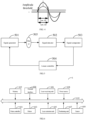
- an error calculation method may include: Referring to FIG. 4 , feedback signal 1 is the feedback signal for the mirror vibrating at the resonant frequency f0.
- the control device pre-stores an amplitude threshold, and a time width corresponding to the amplitude threshold on the feedback signal 1 is a pulse width threshold cpw_G0; and a feedback signal 2 is an actual feedback signal for the mirror, a pulse width cpw_Gn on the feedback signal 2 is determined based on the amplitude threshold, a difference between a pulse width threshold and an actual pulse width is obtained, and an absolute value
- the amplitude threshold is 10 mv
- the pulse width threshold is 5s
- the control device detects the feedback signal for the mirror, and determines that an actual pulse width corresponding to the amplitude threshold on the feedback signal for the mirror is 4.5s
- the control device calculates an absolute value of a difference between the pulse width threshold of 5s and 4.5s to be 0.5s, and uses 0.5s as the error.
- an error calculation method may include: calculating the difference between the amplitude threshold and the maximum amplitude threshold of the feedback signal and using the difference as the error.
- the amplitude threshold pre-stored in the control device is 5 mV
- the control device determines that the maximum amplitude threshold of the feedback signal is 4 mV
- the control device calculates an absolute value of a difference between the amplitude threshold and the maximum amplitude gain to be 0.5 mV and uses 0.5 mV as the error.
- error calculation includes: calculating the difference between the actual amplitude gain of the feedback signal and the amplitude gain threshold, and using the absolute value of the difference as the error.
- the actual amplitude gain of the feedback signal is 35 dB
- the pre-stored amplitude gain threshold of the control signal is 40 dB
- the control device calculates an absolute value of a difference between the actual amplitude gain and the amplitude gain threshold to be 5 dB, and uses 5 dB as the error.
- the frequency adjustment is used to adjust the frequency of a signal generator, and the frequency adjustment has a sign.
- the sign of the frequency adjustment is a plus sign
- current frequency of the signal generator is increased by the frequency adjustment; or when the sign of the frequency adjustment is a minus sign, the current frequency of the signal generator is reduced by the frequency adjustment.
- the control device may determine the frequency adjustment according to the error obtained in S303 based on a linear closed-loop control algorithm.
- the linear closed-loop control algorithm refers to a negative feedback adjustment algorithm with a linear relationship between the error and the frequency adjustment.
- the linear closed-loop control algorithm includes but is not limited to any one of a proportional-integral control algorithm, a proportional-derivative control algorithm, and a proportional control algorithm.
- the current frequency of the control signal output by the signal generator is 100 kHz
- the frequency adjustment is +10 kHz
- a method for determining a sign of a frequency adjustment includes:
- the sign of the frequency adjustment is a plus sign or a minus sign.
- the frequency adjustment When the frequency adjustment is positive, it indicates an increase by the frequency adjustment; or when the frequency adjustment is negative, it indicates a decrease by the frequency adjustment.
- the current error calculated by the control device is W(n), and the current frequency adjustment is ⁇ f(n); the last error obtained is W(n - 1), and a sign of the last frequency adjustment is S(n - 1). W(n) and W(n - 1) are compared.
- the last error stored in the control device is a1 s, and the sign of the last frequency adjustment is +; and the control device calculates the current error to be a2 s, and determines that the current error of a2 s is greater than the last error of a1 s, and the control device negates the sign + of the last frequency adjustment to obtain the sign -.
- the current frequency adjustment is 10 kHz, and the control device instructs the signal generator to reduce the current frequency by 10 kHz.
- the last error stored in the control device is a1 s, and the sign of the last frequency adjustment is +; and the control device calculates the current error to be a2 s, and determines that the current error of a2 s is less than the last error of a1 s, and the control device uses the sign + of the last frequency adjustment as the sign of the current frequency adjustment.
- the current frequency adjustment is 10 kHz, and the control device instructs the signal generator to increase the current frequency by 10 kHz.
- the method before the determining a frequency adjustment based on the error, the method further includes: determining that the error is greater than an error threshold.
- control device pre-stores the error threshold, and the control device determines whether the current error is greater than the error threshold; and if yes, S304 is performed; or if no, frequency adjustment is not performed.
- the control signal used to control the mirror to perform scanning is output, the feedback signal indicating a motion state of the mirror is detected, the frequency adjustment is determined based on the error of the actual amplitude gain relative to the amplitude gain threshold that is obtained through the feedback signal, and frequency is adjusted based on the frequency adjustment, to obtain the control signal for driving the mirror scanning, to implement closed-loop control of the amplitude gain of the mirror and control stability of the amplitude gain of the mirror, thereby resolving a problem that a scanning angle of the mirror changes due to the change in the amplitude gain when resonance frequency deviates because a phase-locked loop is used in a related art.
- the mirror scans with a stable amplitude gain, thereby ensuring that the mirror scans at a specified scanning angle.
- a device embodiment of this application is provided below, and can be used to perform the method embodiments of this application. For details not disclosed in this device embodiment of this application, refer to the method embodiments of this application.
- FIG. 5 is a schematic structural diagram of a mirror control device according to an example embodiment of this application.
- the mirror control device is referred to as a control device 5 below.
- the control device 5 can become all or a part of the LiDAR through software, hardware or a combination of thereof.
- the control device 5 includes: a signal generator 501, a signal detector 502, a signal comparator 503, and a linear controller 504.
- the signal generator 501 is connected to the mirror 505, the mirror 505 is connected to the signal detector 502, the signal detector 502 is connected to the signal comparator 503, the signal comparator 503 is connected to the linear controller 504, and the linear controller 504 is connected to the signal generator 501.
- the signal generator 501, the mirror 505, the signal detector 502, the signal comparator 503, and the linear controller 504 form a feedback control loop.
- the type of linear controller 504 may be a proportional-integral controller or a proportional controller.
- the signal generator 501 is configured to output a control signal, where the control signal is used to control the mirror to perform scanning.
- the signal detector 502 is configured to detect a feedback signal of the scanning mirror 505.
- the signal comparator 503 is configured to determine an actual amplitude gain of the mirror based on the feedback signal, and determine an error of the actual amplitude gain relative to a preset amplitude gain threshold.
- the linear controller 504 is configured to determine a frequency adjustment based on the error, adjust frequency based on the frequency adjustment, and obtain an output signal.
- obtaining an output signal includes:
- determining an error of an actual amplitude gain relative to an amplitude gain threshold includes:
- the error is an absolute value of a difference between the actual pulse width and the pulse width threshold.
- determining a frequency adjustment based on the error includes:
- determining a frequency adjustment based on the error includes: determining the frequency adjustment corresponding to the error based on a linear closed-loop control algorithm.
- the signal comparator 503 is further configured to determine that the error is greater than a preset error threshold.
- control device 5 when the control device 5 provided in the foregoing embodiment performs the mirror control method, division of the foregoing functional modules is used as an example for illustration. In actual application, the foregoing functions can be allocated to different functional modules for implementation based on a requirement, that is, an inner structure of the device is divided into different functional modules to implement all or some of the functions described above.
- embodiments of the mirror control device and the mirror control method provided above pertain to a same concept. For a specific implementation process, refer to the method embodiments. Details are not described herein again.
- An embodiment of this application also provides a computer storage medium.
- the computer storage medium may store a plurality of instructions.
- the instructions are capable of being loaded by a processor to perform the steps of the method in the embodiments shown in FIG. 3 to FIG. 4 .
- For a specific execution process refer to the specific description of the embodiments shown in FIG. 3 to FIG. 4 . Details are not described herein again.
- This application also provides a computer program product.
- the computer program product stores at least one instruction.
- the at least one instruction is loaded and executed by the processor to implement the mirror control method in the foregoing embodiments.
- FIG. 6 is a schematic structural diagram of a LiDAR according to an embodiment of this application.
- LiDAR 6 may include: at least one main controller 601, a memory 602, a mirror 603, and at least one communications bus 610.
- the communications bus 610 is configured to implement a connection and communication between various components in the LiDAR.
- the communications bus 610 is a CAN (controller area network) bus.
- the LiDAR 6 further includes: an external interface 604, a laser emission unit 605, a laser receiving unit 606, a positioning unit 607, a power source 608, and a sensor 609.
- the external interface 604 is used for data transmission with a peripheral device.
- the external interface 604 includes a serial port, a local area network interface, and the like.
- the laser emission unit 605 is configured to emit a laser for detecting an object.
- the laser emission unit 605 may include a boost power source, an LD driving switch, a laser device, an emission temperature control unit, and a power supply.
- the laser receiving unit 606 receives the laser reflected by the object.
- the power source 608 is configured to provide a working voltage for the LiDAR.
- the positioning unit 607 is configured to obtain position information.
- the positioning unit 607 may be a GPS (Global Positioning System) positioning unit.
- the sensor 609 is configured to measure an environmental parameter or an attitude parameter.
- the sensor 609 includes a temperature sensor and an attitude sensor, the temperature sensor is configured to detect ambient temperature, and the attitude sensor is configured to detect a current attitude.
- the main controller 601 may include one or more processing cores.
- the main controller 601 uses various interfaces and lines to connect various parts of the entire LiDAR 6, and executes various functions and processes data of the LiDAR 6 by running or executing instructions, programs, code sets, or instruction sets stored in the memory 602, and invoking data stored in the memory 602.
- the main controller 601 may be realized in at least one hardware form of digital signal processing (DSP), a field-programmable gate array (FPGA), and a programmable logic array (PLA).
- DSP digital signal processing
- FPGA field-programmable gate array
- PDA programmable logic array
- the main controller 601 may integrate a combination of one or more of a central processing unit (CPU), a graphics processing unit (GPU), a modem, and the like.
- the GPU is configured to render and draw content that needs to be displayed on a display.
- the modem is configured to process wireless communication. It may be understood that the forgoing modem may not be integrated into the main controller 60
- the memory 602 may include a random access memory (RAM), or a read-only memory (ROM).
- the memory 602 includes a non-transitory computer-readable medium.
- the memory 602 may be configured to store the instructions, the programs, the codes, the code sets or the instruction sets.
- the memory 602 may include a program storage region and a data storage region.
- the program storage region may store instructions for implementing the operating system, instructions for at least one function (such as a touch control function, a sound play function, and an image play function), and instructions for implementing each of the foregoing method embodiments.
- the memory 602 may also be at least one storage device distant from the forgoing main controller 601.
- the main controller 601 may be configured to invoke the computer program stored in the memory 602, and specifically execute the following steps:
- said obtaining, by the main controller 601, a control signal includes:
- determining, by the main controller 601, an error of an actual amplitude gain relative to an amplitude gain threshold includes:
- the error is an absolute value of a difference between the actual pulse width and the pulse width threshold.
- determining, by the main controller 601, a frequency adjustment based on the error includes:
- determining, by the main controller 601, a frequency adjustment based on the error includes: determining the frequency adjustment corresponding to the error based on a linear closed-loop control algorithm.
- the main controller 601 is further configured to determine that the error is greater than a preset error threshold.
- FIG. 6 and the method embodiment in FIG. 3 are based on the same concept, and have the same technical effects.
- FIG. 6 For a specific implementation process of FIG. 6 , refer to the description of FIG. 3 . Details are not described herein again.
- the person skilled in the art can understand that all or part of procedures in methods of the forgoing embodiments can be implemented by instructing relevant hardware via computer program.
- the program can be stored in a computer readable storage medium. During execution, the computer program can include the procedures of the embodiments of the forgoing methods.
- a storage medium can be a magnetic disk, an optical disc, the read-only storage memory or the random storage memory, and so on.
Landscapes
- Physics & Mathematics (AREA)
- Engineering & Computer Science (AREA)
- General Physics & Mathematics (AREA)
- Automation & Control Theory (AREA)
- Computer Networks & Wireless Communication (AREA)
- Radar, Positioning & Navigation (AREA)
- Remote Sensing (AREA)
- Optics & Photonics (AREA)
- Health & Medical Sciences (AREA)
- Artificial Intelligence (AREA)
- Computer Vision & Pattern Recognition (AREA)
- Evolutionary Computation (AREA)
- Medical Informatics (AREA)
- Software Systems (AREA)
- Mechanical Optical Scanning Systems (AREA)
- Optical Radar Systems And Details Thereof (AREA)
Claims (4)
- Procédé de commande de miroir, dans lequel le procédé comprend :émettre un signal de commande configuré pour commander un miroir de balayage (505) afin d'effectuer un balayage (S301) ;détecter un signal de rétroaction du miroir de balayage (505) (S302);déterminer un gain d'amplitude réel du miroir de balayage (505) sur la base du signal de rétroaction;déterminer une erreur du gain d'amplitude réel par rapport à un seuil de gain d'amplitude prédéfini (S303); etdéterminer un ajustement de fréquence sur la base de l'erreur, ajuster une fréquence d'un générateur de signal (501) sur la base de l'ajustement de fréquence déterminé pour obtenir un signal de sortie (S304),caractérisé en ce que:
l'étape de détermination d'une erreur du gain d'amplitude réel par rapport à un seuil de gain d'amplitude prédéfini (S303) comprend :calculer une différence entre le gain d'amplitude réel du signal de rétroaction et le seuil de gain d'amplitude, et en utilisant la valeur absolue de la différence comme erreur;l'étape de détermination d'un ajustement de fréquence sur la base de l'erreur (S304) comprend:obtenir une dernière erreur et un signe d'un dernier ajustement de fréquence qui sont pré-stockés, déterminer si l'erreur déterminée est supérieure à la dernière erreur,si l'erreur déterminée est supérieure à la dernière erreur, prendre un opposé du signe du dernier réglage de fréquence pour servir de signe du réglage de fréquence déterminé,si l'erreur déterminée n'est pas supérieure à la dernière erreur, utiliser le signe du dernier ajustement de fréquence comme signe de l'ajustement de fréquence déterminé, etstocker l'erreur déterminée et le signe de l'ajustement de fréquence déterminé. - Procédé de commande de miroir selon la revendication 1, dans lequel ladite délivrance d'un signal de commande comprend :générer un signal monofréquence ; eteffectuer un traitement d'amplification sur le signal monofréquence, pour obtenir le signal de commande.
- Dispositif de commande de miroir (5), dans lequel le dispositif de commande (5) comprend :un générateur de signal (501), configuré pour émettre un signal de commande (301), le signal de commande étant utilisé pour commander un miroir de balayage (505) afin d'effectuer un balayage ;un détecteur de signal (502), configuré pour détecter un signal de rétroaction du miroir de balayage (505) (302);un comparateur de signaux (503), configuré pour: déterminer un gain d'amplitude réel du miroir de balayage (505) sur la base du signal de rétroaction, etdéterminer une erreur du gain d'amplitude réel par rapport à un seuil de gain d'amplitude prédéfini (S303); etun contrôleur linéaire (504), configuré pour déterminer un ajustement de fréquence sur la base de l'erreur, et ajuster une fréquence du générateur de signal (501) sur la base de l'ajustement de fréquence déterminé pour obtenir un signal de sortie (S304);caractérisé en ce que:
le comparateur de signaux (503) est configuré pour déterminer une erreur du gain d'amplitude réel par rapport au seuil de gain d'amplitude prédéfini (S303) en:calculer une différence entre le gain d'amplitude réel du signal de rétroaction et le seuil de gain d'amplitude, et utiliser la valeur absolue de la différence comme erreur; etle contrôleur linéaire (504) est configuré pour déterminer un ajustement de fréquence sur la base de l'erreur (S304) en:obtenir une dernière erreur et un signe d'un dernier ajustement de fréquence qui sont pré-stockés, déterminer si l'erreur déterminée est supérieure à la dernière erreur,si l'erreur déterminée est supérieure à la dernière erreur, prendre un opposé du signe du dernier réglage de fréquence pour servir de signe du réglage de fréquence déterminé,si l'erreur déterminée n'est pas supérieure à la dernière erreur, utiliser le signe du dernier ajustement de fréquence comme signe de l'ajustement de fréquence déterminé, etstocker l'erreur déterminée et le signe de l'ajustement de fréquence déterminé. - Dispositif de commande de miroir (5) selon la revendication 3, dans lequel le contrôleur linéaire (504) est un contrôleur proportionnel-intégral.
Applications Claiming Priority (1)
| Application Number | Priority Date | Filing Date | Title |
|---|---|---|---|
| PCT/CN2019/109478 WO2021051454A1 (fr) | 2019-09-30 | 2019-09-30 | Procédé de commande et dispositif de commande pour galvanomètre lidar et lidar |
Publications (4)
| Publication Number | Publication Date |
|---|---|
| EP4040215A1 EP4040215A1 (fr) | 2022-08-10 |
| EP4040215A4 EP4040215A4 (fr) | 2022-11-02 |
| EP4040215C0 EP4040215C0 (fr) | 2024-01-17 |
| EP4040215B1 true EP4040215B1 (fr) | 2024-01-17 |
Family
ID=74884402
Family Applications (1)
| Application Number | Title | Priority Date | Filing Date |
|---|---|---|---|
| EP19945479.4A Active EP4040215B1 (fr) | 2019-09-30 | 2019-09-30 | Procédé de commande et dispositif de commande pour galvanomètre lidar et lidar |
Country Status (4)
| Country | Link |
|---|---|
| US (1) | US11536954B2 (fr) |
| EP (1) | EP4040215B1 (fr) |
| CN (1) | CN112888985B (fr) |
| WO (1) | WO2021051454A1 (fr) |
Families Citing this family (6)
| Publication number | Priority date | Publication date | Assignee | Title |
|---|---|---|---|---|
| CN113625247B (zh) * | 2021-10-11 | 2022-03-04 | 北京一径科技有限公司 | 一种控制方法、装置及激光雷达 |
| CN114839621B (zh) * | 2022-03-28 | 2026-01-16 | 武汉万集光电技术有限公司 | Mems振镜状态检测方法及mems激光雷达 |
| CN116047749A (zh) * | 2022-11-04 | 2023-05-02 | 深圳市镭神智能系统有限公司 | 微振镜控制方法、控制系统及电子设备 |
| CN115951489A (zh) * | 2022-12-29 | 2023-04-11 | 深圳市镭神智能系统有限公司 | 微镜偏振运动控制方法、装置、校准设备及可读存储介质 |
| CN116400374B (zh) * | 2023-05-04 | 2024-05-03 | 深圳市华众自动化工程有限公司 | 一种基于高精度激光信号采集的测量装置及方法 |
| CN118707712B (zh) * | 2024-07-08 | 2025-02-14 | 深圳市鹏鼎智控科技有限公司 | 一种振镜控制系统 |
Family Cites Families (13)
| Publication number | Priority date | Publication date | Assignee | Title |
|---|---|---|---|---|
| US5204848A (en) * | 1991-06-17 | 1993-04-20 | International Business Machines Corporation | Adjusting amplitude detection threshold by feeding back timing-data phase errors |
| US5757751A (en) * | 1996-01-16 | 1998-05-26 | International Business Machines Corporation | Baseline correction circuit for pulse width modulated data readback systems |
| US6956597B2 (en) * | 2002-12-23 | 2005-10-18 | Lexmark International, Inc. | Scanning with multiple oscillating scanners |
| US7107848B2 (en) * | 2004-12-03 | 2006-09-19 | Texas Instruments Incorporated | Active scan velocity control for torsional hinged MEMS scanner |
| CN101008837A (zh) * | 2006-01-26 | 2007-08-01 | 深圳市大族激光科技股份有限公司 | 振镜驱动器的调节装置及其调节方法 |
| JP2009058616A (ja) * | 2007-08-30 | 2009-03-19 | Canon Inc | 揺動体装置、光偏向装置、及びそれを用いた画像形成装置 |
| CN101477248B (zh) * | 2009-01-22 | 2011-04-13 | 中国科学院光电技术研究所 | 双扭杆谐振扫描反射镜 |
| CN101778325A (zh) * | 2010-01-28 | 2010-07-14 | 无锡职业技术学院 | 基于硅基电容式微麦克风的微电机械镜运动反馈控制系统 |
| JP6069628B2 (ja) * | 2012-12-03 | 2017-02-01 | 北陽電機株式会社 | 偏向装置、光走査装置及び走査式測距装置 |
| CN106526834B (zh) * | 2016-10-21 | 2019-01-11 | 深圳市微觉未来科技有限公司 | 一种扫描反射镜及其扫描方法 |
| CN107526096B (zh) * | 2017-08-15 | 2019-06-25 | 江苏超敏仪器有限公司 | 一种修正温度对SiPM增益影响的方法 |
| CN108089177A (zh) * | 2018-01-30 | 2018-05-29 | 深圳市速腾聚创科技有限公司 | 激光雷达及激光雷达控制方法 |
| CN108594869B (zh) * | 2018-01-09 | 2021-04-16 | 南京理工大学 | 一种基于谐振点实时估算的微镜控制方法及其系统 |
-
2019
- 2019-09-30 EP EP19945479.4A patent/EP4040215B1/fr active Active
- 2019-09-30 CN CN201980064316.8A patent/CN112888985B/zh active Active
- 2019-09-30 WO PCT/CN2019/109478 patent/WO2021051454A1/fr not_active Ceased
-
2022
- 2022-03-29 US US17/707,931 patent/US11536954B2/en active Active
Also Published As
| Publication number | Publication date |
|---|---|
| CN112888985A (zh) | 2021-06-01 |
| US20220221711A1 (en) | 2022-07-14 |
| EP4040215A4 (fr) | 2022-11-02 |
| EP4040215C0 (fr) | 2024-01-17 |
| WO2021051454A1 (fr) | 2021-03-25 |
| US11536954B2 (en) | 2022-12-27 |
| CN112888985B (zh) | 2022-04-05 |
| EP4040215A1 (fr) | 2022-08-10 |
Similar Documents
| Publication | Publication Date | Title |
|---|---|---|
| US11536954B2 (en) | LiDAR mirror control method and device and LiDAR | |
| US9268316B2 (en) | Method for automatically estimating a friction coefficient in a mechanical system | |
| JP7762858B2 (ja) | 対象物の距離および/または速度を計測する装置および方法 | |
| US11742864B2 (en) | Adaptive phase lock loop that adjusts its phase difference target | |
| WO2021184206A1 (fr) | Procédé et dispositif de correction de fréquence balayée linéairement, support de stockage, et système | |
| EP4273506A1 (fr) | Procédé et système d'étalonnage d'un dispositif de balayage laser | |
| US20160178732A1 (en) | Radar device and signal processing method | |
| CN115275772B (zh) | 一种基于tdlas技术的特定时刻激光波长控制方法及装置 | |
| WO2023005986A1 (fr) | Procédé de détection de système de détection, et système de détection, dispositif et support de stockage | |
| JP3656598B2 (ja) | レーダ装置 | |
| US20240077589A1 (en) | Scanning apparatus placement method, apparatus and storage medium | |
| CN115754981B (zh) | 基于振镜的激光控制方法、标定方法、装置和激光雷达 | |
| WO2023116917A2 (fr) | Procédé et appareil de balayage, et support de stockage informatique | |
| JP7283560B2 (ja) | レーザセンサ、ミラー制御方法、及びプログラム | |
| CN108922461A (zh) | 微激光投影仪、基于微激光投影仪的信号处理方法及设备 | |
| US10649204B2 (en) | Device and method for deflecting a light beam in order to scan a solid angle range | |
| JPWO2018101293A1 (ja) | 計測装置、設定装置、設定方法、修正方法、及びプログラム | |
| CN117982202B (zh) | 频率跟踪方法、计算机设备及存储介质 | |
| KR102685333B1 (ko) | 라이다 센서 장치 및 그 제어 방법 | |
| US20260098943A1 (en) | Laser scanning device, laser scanning method and program for laser scanning | |
| CN217560592U (zh) | 一种共振式扫描镜的偏摆角检测装置 | |
| US20240085541A1 (en) | Frame synchronization method and apparatus for lidar system, and computer-readable storage medium | |
| JP2025127626A (ja) | 光走査装置 | |
| JP2024123843A (ja) | ミラー制御方法、ミラー制御プログラム及びミラー制御装置 | |
| CN115075588A (zh) | 一种施工调平方法、装置、施工设备及存储介质 |
Legal Events
| Date | Code | Title | Description |
|---|---|---|---|
| STAA | Information on the status of an ep patent application or granted ep patent |
Free format text: STATUS: THE INTERNATIONAL PUBLICATION HAS BEEN MADE |
|
| PUAI | Public reference made under article 153(3) epc to a published international application that has entered the european phase |
Free format text: ORIGINAL CODE: 0009012 |
|
| STAA | Information on the status of an ep patent application or granted ep patent |
Free format text: STATUS: REQUEST FOR EXAMINATION WAS MADE |
|
| 17P | Request for examination filed |
Effective date: 20220428 |
|
| AK | Designated contracting states |
Kind code of ref document: A1 Designated state(s): AL AT BE BG CH CY CZ DE DK EE ES FI FR GB GR HR HU IE IS IT LI LT LU LV MC MK MT NL NO PL PT RO RS SE SI SK SM TR |
|
| A4 | Supplementary search report drawn up and despatched |
Effective date: 20220929 |
|
| RIC1 | Information provided on ipc code assigned before grant |
Ipc: G01S 7/481 20060101ALI20220923BHEP Ipc: G02B 26/10 20060101AFI20220923BHEP |
|
| DAV | Request for validation of the european patent (deleted) | ||
| DAX | Request for extension of the european patent (deleted) | ||
| GRAP | Despatch of communication of intention to grant a patent |
Free format text: ORIGINAL CODE: EPIDOSNIGR1 |
|
| STAA | Information on the status of an ep patent application or granted ep patent |
Free format text: STATUS: GRANT OF PATENT IS INTENDED |
|
| INTG | Intention to grant announced |
Effective date: 20230817 |
|
| GRAS | Grant fee paid |
Free format text: ORIGINAL CODE: EPIDOSNIGR3 |
|
| GRAA | (expected) grant |
Free format text: ORIGINAL CODE: 0009210 |
|
| STAA | Information on the status of an ep patent application or granted ep patent |
Free format text: STATUS: THE PATENT HAS BEEN GRANTED |
|
| AK | Designated contracting states |
Kind code of ref document: B1 Designated state(s): AL AT BE BG CH CY CZ DE DK EE ES FI FR GB GR HR HU IE IS IT LI LT LU LV MC MK MT NL NO PL PT RO RS SE SI SK SM TR |
|
| REG | Reference to a national code |
Ref country code: GB Ref legal event code: FG4D |
|
| REG | Reference to a national code |
Ref country code: DE Ref legal event code: R096 Ref document number: 602019045405 Country of ref document: DE |
|
| REG | Reference to a national code |
Ref country code: CH Ref legal event code: EP |
|
| REG | Reference to a national code |
Ref country code: IE Ref legal event code: FG4D |
|
| U01 | Request for unitary effect filed |
Effective date: 20240216 |
|
| U07 | Unitary effect registered |
Designated state(s): AT BE BG DE DK EE FI FR IT LT LU LV MT NL PT SE SI Effective date: 20240226 |
|
| PG25 | Lapsed in a contracting state [announced via postgrant information from national office to epo] |
Ref country code: IS Free format text: LAPSE BECAUSE OF FAILURE TO SUBMIT A TRANSLATION OF THE DESCRIPTION OR TO PAY THE FEE WITHIN THE PRESCRIBED TIME-LIMIT Effective date: 20240517 |
|
| PG25 | Lapsed in a contracting state [announced via postgrant information from national office to epo] |
Ref country code: GR Free format text: LAPSE BECAUSE OF FAILURE TO SUBMIT A TRANSLATION OF THE DESCRIPTION OR TO PAY THE FEE WITHIN THE PRESCRIBED TIME-LIMIT Effective date: 20240418 |
|
| PG25 | Lapsed in a contracting state [announced via postgrant information from national office to epo] |
Ref country code: HR Free format text: LAPSE BECAUSE OF FAILURE TO SUBMIT A TRANSLATION OF THE DESCRIPTION OR TO PAY THE FEE WITHIN THE PRESCRIBED TIME-LIMIT Effective date: 20240117 Ref country code: RS Free format text: LAPSE BECAUSE OF FAILURE TO SUBMIT A TRANSLATION OF THE DESCRIPTION OR TO PAY THE FEE WITHIN THE PRESCRIBED TIME-LIMIT Effective date: 20240417 |
|
| PG25 | Lapsed in a contracting state [announced via postgrant information from national office to epo] |
Ref country code: ES Free format text: LAPSE BECAUSE OF FAILURE TO SUBMIT A TRANSLATION OF THE DESCRIPTION OR TO PAY THE FEE WITHIN THE PRESCRIBED TIME-LIMIT Effective date: 20240117 |
|
| PG25 | Lapsed in a contracting state [announced via postgrant information from national office to epo] |
Ref country code: RS Free format text: LAPSE BECAUSE OF FAILURE TO SUBMIT A TRANSLATION OF THE DESCRIPTION OR TO PAY THE FEE WITHIN THE PRESCRIBED TIME-LIMIT Effective date: 20240417 Ref country code: NO Free format text: LAPSE BECAUSE OF FAILURE TO SUBMIT A TRANSLATION OF THE DESCRIPTION OR TO PAY THE FEE WITHIN THE PRESCRIBED TIME-LIMIT Effective date: 20240417 Ref country code: IS Free format text: LAPSE BECAUSE OF FAILURE TO SUBMIT A TRANSLATION OF THE DESCRIPTION OR TO PAY THE FEE WITHIN THE PRESCRIBED TIME-LIMIT Effective date: 20240517 Ref country code: HR Free format text: LAPSE BECAUSE OF FAILURE TO SUBMIT A TRANSLATION OF THE DESCRIPTION OR TO PAY THE FEE WITHIN THE PRESCRIBED TIME-LIMIT Effective date: 20240117 Ref country code: GR Free format text: LAPSE BECAUSE OF FAILURE TO SUBMIT A TRANSLATION OF THE DESCRIPTION OR TO PAY THE FEE WITHIN THE PRESCRIBED TIME-LIMIT Effective date: 20240418 Ref country code: ES Free format text: LAPSE BECAUSE OF FAILURE TO SUBMIT A TRANSLATION OF THE DESCRIPTION OR TO PAY THE FEE WITHIN THE PRESCRIBED TIME-LIMIT Effective date: 20240117 |
|
| PG25 | Lapsed in a contracting state [announced via postgrant information from national office to epo] |
Ref country code: PL Free format text: LAPSE BECAUSE OF FAILURE TO SUBMIT A TRANSLATION OF THE DESCRIPTION OR TO PAY THE FEE WITHIN THE PRESCRIBED TIME-LIMIT Effective date: 20240117 |
|
| PG25 | Lapsed in a contracting state [announced via postgrant information from national office to epo] |
Ref country code: PL Free format text: LAPSE BECAUSE OF FAILURE TO SUBMIT A TRANSLATION OF THE DESCRIPTION OR TO PAY THE FEE WITHIN THE PRESCRIBED TIME-LIMIT Effective date: 20240117 |
|
| U20 | Renewal fee for the european patent with unitary effect paid |
Year of fee payment: 6 Effective date: 20240827 |
|
| PG25 | Lapsed in a contracting state [announced via postgrant information from national office to epo] |
Ref country code: SM Free format text: LAPSE BECAUSE OF FAILURE TO SUBMIT A TRANSLATION OF THE DESCRIPTION OR TO PAY THE FEE WITHIN THE PRESCRIBED TIME-LIMIT Effective date: 20240117 |
|
| REG | Reference to a national code |
Ref country code: DE Ref legal event code: R097 Ref document number: 602019045405 Country of ref document: DE |
|
| PG25 | Lapsed in a contracting state [announced via postgrant information from national office to epo] |
Ref country code: CZ Free format text: LAPSE BECAUSE OF FAILURE TO SUBMIT A TRANSLATION OF THE DESCRIPTION OR TO PAY THE FEE WITHIN THE PRESCRIBED TIME-LIMIT Effective date: 20240117 |
|
| PG25 | Lapsed in a contracting state [announced via postgrant information from national office to epo] |
Ref country code: SK Free format text: LAPSE BECAUSE OF FAILURE TO SUBMIT A TRANSLATION OF THE DESCRIPTION OR TO PAY THE FEE WITHIN THE PRESCRIBED TIME-LIMIT Effective date: 20240117 |
|
| PG25 | Lapsed in a contracting state [announced via postgrant information from national office to epo] |
Ref country code: SM Free format text: LAPSE BECAUSE OF FAILURE TO SUBMIT A TRANSLATION OF THE DESCRIPTION OR TO PAY THE FEE WITHIN THE PRESCRIBED TIME-LIMIT Effective date: 20240117 Ref country code: SK Free format text: LAPSE BECAUSE OF FAILURE TO SUBMIT A TRANSLATION OF THE DESCRIPTION OR TO PAY THE FEE WITHIN THE PRESCRIBED TIME-LIMIT Effective date: 20240117 Ref country code: RO Free format text: LAPSE BECAUSE OF FAILURE TO SUBMIT A TRANSLATION OF THE DESCRIPTION OR TO PAY THE FEE WITHIN THE PRESCRIBED TIME-LIMIT Effective date: 20240117 Ref country code: CZ Free format text: LAPSE BECAUSE OF FAILURE TO SUBMIT A TRANSLATION OF THE DESCRIPTION OR TO PAY THE FEE WITHIN THE PRESCRIBED TIME-LIMIT Effective date: 20240117 |
|
| PLBE | No opposition filed within time limit |
Free format text: ORIGINAL CODE: 0009261 |
|
| STAA | Information on the status of an ep patent application or granted ep patent |
Free format text: STATUS: NO OPPOSITION FILED WITHIN TIME LIMIT |
|
| 26N | No opposition filed |
Effective date: 20241018 |
|
| PG25 | Lapsed in a contracting state [announced via postgrant information from national office to epo] |
Ref country code: MC Free format text: LAPSE BECAUSE OF FAILURE TO SUBMIT A TRANSLATION OF THE DESCRIPTION OR TO PAY THE FEE WITHIN THE PRESCRIBED TIME-LIMIT Effective date: 20240117 |
|
| REG | Reference to a national code |
Ref country code: CH Ref legal event code: PL |
|
| GBPC | Gb: european patent ceased through non-payment of renewal fee |
Effective date: 20240930 |
|
| PG25 | Lapsed in a contracting state [announced via postgrant information from national office to epo] |
Ref country code: GB Free format text: LAPSE BECAUSE OF NON-PAYMENT OF DUE FEES Effective date: 20240930 |
|
| PG25 | Lapsed in a contracting state [announced via postgrant information from national office to epo] |
Ref country code: CH Free format text: LAPSE BECAUSE OF NON-PAYMENT OF DUE FEES Effective date: 20240930 |
|
| PG25 | Lapsed in a contracting state [announced via postgrant information from national office to epo] |
Ref country code: IE Free format text: LAPSE BECAUSE OF NON-PAYMENT OF DUE FEES Effective date: 20240930 |
|
| U20 | Renewal fee for the european patent with unitary effect paid |
Year of fee payment: 7 Effective date: 20250826 |
|
| PG25 | Lapsed in a contracting state [announced via postgrant information from national office to epo] |
Ref country code: CY Free format text: LAPSE BECAUSE OF FAILURE TO SUBMIT A TRANSLATION OF THE DESCRIPTION OR TO PAY THE FEE WITHIN THE PRESCRIBED TIME-LIMIT; INVALID AB INITIO Effective date: 20190930 |
|
| PG25 | Lapsed in a contracting state [announced via postgrant information from national office to epo] |
Ref country code: HU Free format text: LAPSE BECAUSE OF FAILURE TO SUBMIT A TRANSLATION OF THE DESCRIPTION OR TO PAY THE FEE WITHIN THE PRESCRIBED TIME-LIMIT; INVALID AB INITIO Effective date: 20190930 |