EP4040393A1 - Teilungsverfahren, codierer, decodierer und computerspeichermedium - Google Patents
Teilungsverfahren, codierer, decodierer und computerspeichermedium Download PDFInfo
- Publication number
- EP4040393A1 EP4040393A1 EP19947936.1A EP19947936A EP4040393A1 EP 4040393 A1 EP4040393 A1 EP 4040393A1 EP 19947936 A EP19947936 A EP 19947936A EP 4040393 A1 EP4040393 A1 EP 4040393A1
- Authority
- EP
- European Patent Office
- Prior art keywords
- point cloud
- iteration
- points
- input point
- lod
- Prior art date
- Legal status (The legal status is an assumption and is not a legal conclusion. Google has not performed a legal analysis and makes no representation as to the accuracy of the status listed.)
- Granted
Links
Images




Classifications
-
- G—PHYSICS
- G06—COMPUTING OR CALCULATING; COUNTING
- G06T—IMAGE DATA PROCESSING OR GENERATION, IN GENERAL
- G06T9/00—Image coding
- G06T9/40—Tree coding, e.g. quadtree, octree
-
- G—PHYSICS
- G06—COMPUTING OR CALCULATING; COUNTING
- G06T—IMAGE DATA PROCESSING OR GENERATION, IN GENERAL
- G06T17/00—Three-dimensional [3D] modelling for computer graphics
- G06T17/005—Tree description, e.g. octree, quadtree
-
- G—PHYSICS
- G06—COMPUTING OR CALCULATING; COUNTING
- G06T—IMAGE DATA PROCESSING OR GENERATION, IN GENERAL
- G06T7/00—Image analysis
- G06T7/50—Depth or shape recovery
-
- G—PHYSICS
- G06—COMPUTING OR CALCULATING; COUNTING
- G06T—IMAGE DATA PROCESSING OR GENERATION, IN GENERAL
- G06T9/00—Image coding
- G06T9/001—Model-based coding, e.g. wire frame
-
- H—ELECTRICITY
- H04—ELECTRIC COMMUNICATION TECHNIQUE
- H04N—PICTORIAL COMMUNICATION, e.g. TELEVISION
- H04N19/00—Methods or arrangements for coding, decoding, compressing or decompressing digital video signals
- H04N19/10—Methods or arrangements for coding, decoding, compressing or decompressing digital video signals using adaptive coding
- H04N19/102—Methods or arrangements for coding, decoding, compressing or decompressing digital video signals using adaptive coding characterised by the element, parameter or selection affected or controlled by the adaptive coding
- H04N19/119—Adaptive subdivision aspects, e.g. subdivision of a picture into rectangular or non-rectangular coding blocks
-
- H—ELECTRICITY
- H04—ELECTRIC COMMUNICATION TECHNIQUE
- H04N—PICTORIAL COMMUNICATION, e.g. TELEVISION
- H04N19/00—Methods or arrangements for coding, decoding, compressing or decompressing digital video signals
- H04N19/10—Methods or arrangements for coding, decoding, compressing or decompressing digital video signals using adaptive coding
- H04N19/134—Methods or arrangements for coding, decoding, compressing or decompressing digital video signals using adaptive coding characterised by the element, parameter or criterion affecting or controlling the adaptive coding
- H04N19/136—Incoming video signal characteristics or properties
-
- H—ELECTRICITY
- H04—ELECTRIC COMMUNICATION TECHNIQUE
- H04N—PICTORIAL COMMUNICATION, e.g. TELEVISION
- H04N19/00—Methods or arrangements for coding, decoding, compressing or decompressing digital video signals
- H04N19/30—Methods or arrangements for coding, decoding, compressing or decompressing digital video signals using hierarchical techniques, e.g. scalability
-
- H—ELECTRICITY
- H04—ELECTRIC COMMUNICATION TECHNIQUE
- H04N—PICTORIAL COMMUNICATION, e.g. TELEVISION
- H04N19/00—Methods or arrangements for coding, decoding, compressing or decompressing digital video signals
- H04N19/50—Methods or arrangements for coding, decoding, compressing or decompressing digital video signals using predictive coding
- H04N19/593—Methods or arrangements for coding, decoding, compressing or decompressing digital video signals using predictive coding involving spatial prediction techniques
-
- H—ELECTRICITY
- H04—ELECTRIC COMMUNICATION TECHNIQUE
- H04N—PICTORIAL COMMUNICATION, e.g. TELEVISION
- H04N19/00—Methods or arrangements for coding, decoding, compressing or decompressing digital video signals
- H04N19/50—Methods or arrangements for coding, decoding, compressing or decompressing digital video signals using predictive coding
- H04N19/597—Methods or arrangements for coding, decoding, compressing or decompressing digital video signals using predictive coding specially adapted for multi-view video sequence encoding
-
- G—PHYSICS
- G06—COMPUTING OR CALCULATING; COUNTING
- G06T—IMAGE DATA PROCESSING OR GENERATION, IN GENERAL
- G06T2207/00—Indexing scheme for image analysis or image enhancement
- G06T2207/10—Image acquisition modality
- G06T2207/10028—Range image; Depth image; 3D point clouds
Definitions
- Implementations of this application relates to level of detail (LOD) partition technology in geometry-based point cloud compression (G-PCC) coding, and in particular to a partition method, an encoder, a decoder, and a computer storage medium.
- LOD level of detail
- Geometry encoding is first performed. After geometry encoding is completed, geometry information is reconstructed.
- attribute encoding is mainly for color information.
- the color information is first transformed from a RGB color space to a YUV color space. Thereafter, the reconstructed geometry information is used to recolor the point cloud, so that un-encoded attribute information can correspond to the reconstructed geometry information.
- LOD level of detail
- RAHT regional adaptive hierarchical transform
- Implementations of this application provide a partition method, an encoder, a decoder, and a computer storage medium, which can improve the prediction accuracy of neighbor nodes and improve a coding rate.
- implementations of this application provide a partition method.
- the method includes the following.
- a point cloud to-be-partitioned is obtained and Morton codes for the point cloud to-be-partitioned are calculated.
- the point cloud to-be-partitioned is determined as an input point cloud of a first iteration.
- whether a number of points in an input point cloud of the i -th iteration is equal to 0 is determined, where i is a positive integer with an initial value equal to 1.
- Morton codes for the input point cloud of the i -th iteration are right shifted by K bits, where K is a positive integer.
- a point is selected from points with a same value of Morton codes after right shifted by K bits.
- An i -th level of detail (LOD) layer is formed with the point selected, remaining points other than the point selected in the input point cloud of the i -th iteration are determined as an input point cloud of an ( i +1)-th iteration, i is updated to i +1, and return to determine whether the number of points in the input point cloud of the i -th iteration is equal to 0 at the i -th iteration.
- LOD level of detail
- a first to ( i -1)-th LOD layers are determined as LOD layers after partition of the point cloud to-be-partitioned.
- implementations of this application provide an encoder.
- the encoder includes a first calculating module, a first determining module, a first judging module, a first right shifting module, a first selecting module, a first partitioning module, and a second determining module.
- the first calculating module is configured to obtain a point cloud to-be-partitioned and calculate Morton codes for the point cloud to-be-partitioned.
- the first determining module is configured to determine the point cloud to-be-partitioned as an input point cloud of a first iteration.
- the first judging module is configured to determine whether a number of points in an input point cloud of an i -th iteration is equal to 0 at the i -th iteration, where i is a positive integer with an initial value equal to 1.
- the first right shifting module is configured to shift Morton codes for the input point cloud of the i -th iteration right by K bits based on a determination that the number of points in the input point cloud of the i -th iteration is unequal to 0, where K is a positive integer.
- the first selecting module is configured to select a point from points with a same value of Morton codes after right shifted by K bits.
- the first partitioning module is configured to form an i -th LOD layer with the point selected, determine remaining points in the input point cloud of the i -th iteration other than the point selected as an input point cloud of an ( i +1)-th iteration, update i to i +1, and return to the first judging module to determine whether the number of points in the input point cloud of the i -th iteration is equal to 0 at the i -th iteration.
- the second determining module is configured to determine a first to ( i -1)-th LOD layers as LOD layers after partition of the point cloud to-be-partitioned based on a determination that the number of points in the input point cloud of the i -th iteration is equal to 0.
- implementations of this application provide a decoder.
- the decoder includes a second calculating module, a third determining module, a second judging module, a second right shifting module, a second selecting module, a second partitioning module, and a fourth determining module.
- the second calculating module is configured to obtain a point cloud to-be-partitioned and calculate Morton codes for the point cloud to-be-partitioned.
- the third determining module is configured to determine the point cloud to-be-partitioned as an input point cloud of a first iteration.
- the second judging module is configured to determine whether a number of points in an input point cloud of an i -th iteration is equal to 0 at the i -th iteration, where i is a positive integer with an initial value equal to 1.
- the second right shifting module is configured to shift Morton codes for the input point cloud of the i -th iteration right by K bits based on a determination that the number of points in the input point cloud of the i -th iteration is unequal to 0, where K is a positive integer.
- the second selecting module is configured to select a point from points with a same value of Morton codes after right shifted by K bits.
- the second partitioning module is configured to form an i -th level of detail (LOD) layer with the point selected, determine remaining points in the input point cloud of the i -th iteration other than the point selected as an input point cloud of an ( i +1)-th iteration, update i to i +1, and return to the second judging module to determine whether the number of points in the input point cloud of the i -th iteration is equal to 0 at the i- th iteration.
- LOD level of detail
- the fourth determining module is configured to determine a first to ( i -1)-th LOD layers as LOD layers after partition of the point cloud to-be-partitioned based on a determination that the number of points in the input point cloud of the i -th iteration is equal to 0.
- implementations of this application provide an encoder.
- the encoder includes a processor and a storage medium storing instructions executable by the processor.
- the storage medium relies on the processor to execute operations via a communication bus, and when executed by the processor, the instructions executes the partition method of one or more implementations described above.
- implementations of this application provide an encoder.
- the encoder includes a processor and a storage medium storing instructions executable by the processor.
- the storage medium relies on the processor to execute operations via a communication bus, and when executed by the processor, the instructions executes the partition method of one or more implementations described above.
- implementations of this application provide a computer-readable storage medium storing executable instructions.
- the processor executes the partition method of one or more implementations described above.
- Implementations of this application provide a partition method, an encoder, a decoder, and a computer storage medium.
- the method includes the following.
- a point cloud to-be-partitioned is obtained and Morton codes for the point cloud to-be-partitioned are calculated.
- the point cloud to-be-partitioned is determined as an input point cloud of a first iteration.
- i is a positive integer with an initial value equal to 1.
- Morton codes for the input point cloud of the i -th iteration are right shifted by K bits, where K is a positive integer.
- a point is selected from points with a same value of Morton codes after right shifted by K bits.
- An i -th LOD layer is formed with the point selected, remaining points other than the point selected in the input point cloud of the i -th iteration are determined as an input point cloud of an ( i +1)-th iteration, i is updated to i +1, and return to determine whether the number of points in the input point cloud of the i -th iteration is equal to 0 at the i -th iteration. Based on a determination that the number of points in the input point cloud of the i -th iteration is equal to 0, a first to ( i -1)-th LOD layers are determined as LOD layers after partition of the point cloud to-be-partitioned.
- Morton codes for the input point cloud of each iteration are right shifted by K bits. Thereafter, a point is selected from points with the same value of Morton codes after right shifted by K bits, and the point selected forms a LOD layer of the current iteration.
- a distribution of the point cloud and spatial distances between points in the point cloud can be comprehensively considered in a LOD partition process, such that the partition of LOD layers obtained is based on the distribution of the point cloud and the spatial distances between points in the point cloud. As such, a prediction accuracy of neighbor nodes based on LOD layers can be improved, thereby improving coding efficiency.
- G-PCC geometry-based point cloud compression
- FIG. 1 is a block diagram of a process of G-PCC encoding. As illustrated in FIG. 1 , the process is applied to a point cloud encoder. For point cloud data to-be-encoded, through slice partition, the point cloud data is first partitioned into multiple slices. In each slice, geometry information of the point cloud and attribute information corresponding to each point in the point cloud are encoded separately. In geometry encoding, coordinate transform is performed on the geometry information so that the whole point cloud is contained in a bounding box. Then quantification is performed, which mainly plays a role of scaling. Due to the rounding of quantification, the geometry information of part of the point cloud is the same. Then whether to remove duplicate points is decided based on parameters.
- octree partition is performed on the bounding box.
- the bounding box is equally partitioned into eight sub-cubes, and non-empty (including points in the point cloud) sub-cubes continue to be partitioned into eight equal parts until leaf nodes obtained through partition are 1 ⁇ 1 ⁇ 1 unit cubes.
- Arithmetic coding is performed on points in the leaf nodes to generate a binary geometry bitstream, that is, geometry code stream.
- octree partition is also performed first.
- the trisoup does not need to partition the point cloud step by step into unit cubes each with an edge length of 1 ⁇ 1 ⁇ 1, but stops partition when blocks each with an edge length of W are obtained.
- Based on a surface formed based on distribution of a point cloud in each block at most twelve vertexes generated by both the surface and twelve edges of the block are obtained. Arithmetic coding is performed on the vertexes (surface fitting based on vertexes), to generate a binary geometry bitstream, that is, geometry code stream.
- the vertexes are also used in implementation of geometry reconstruction and reconstructed geometry information is used in attribute coding of the point cloud.
- color transform is performed, that is, color information (i.e., the attribute information) is transformed from a RGB color space to a YUV color space. Thereafter, the reconstructed geometry information is used to recolor the point cloud, so that un-encoded attribute information can correspond to the reconstructed geometry information.
- LOD level of detail
- RAHT regional adaptive hierarchical transform
- Both methods transform the color information from a spatial domain to a frequency domain, obtain high-frequency coefficients and low-frequency coefficients through transform, and finally quantize the coefficients (i.e., quantized coefficients).
- geometry encoded data after octree partition and surface fitting and attribute encoded data after quantized coefficient processing are slice-synthesized, and vertex coordinates of each block are encoded in turn (that is, arithmetic coding), to generate a binary attribute bitstream, that is, attribute code stream.
- a distance-based LOD partition method is proposed for Category3 point cloud in attribute transform.
- the distance-based LOD partition method is applied to a TMC3V0 encoder and used in TMC13 attribute lifting transform.
- the distance-based method for LOD partition is also added in TMC13 attribute predicting transform. That is, LOD partition is applied in both point cloud attribute predicting transform and lifting transform.
- the distance-based LOD partition is implemented as follows.
- the process of LOD partition is after the geometry reconstruction of the point cloud.
- the geometry coordinate information of the point cloud is known.
- the process of LOD partition is applied at both the encoder side and the decoder side for the point cloud. The process proceeds as follows:
- FIG. 2 is a schematic diagram of a process of distance-based LOD partition.
- a current point cloud to-be-partitioned includes points P0, P1, P2, P3, P4, P5, P6, P7, P8, and P9, where an original point cloud order is: P0, P1, P2, P3, P4, P5, P6, P7, P8, and P9.
- LOD0 obtained by the distance-based method for LOD partition includes P4, P5, P0, and P1, LOD1 includes P4, P5, P0, P1, P3, P2, and P6, and LOD2 includes P4, P5, P0, P1, P3, P2, P6, P7, P8, and P9.
- the Morton code M is obtained by interleaving x l , y l , z l from the most significant bits to the least significant bits for x, y, z.
- D0 (representing a threshold of an initial distance) and ⁇ (representing a distance threshold ratio in partition of adjacent LOD layers) are user-defined initial parameters respectively, and ⁇ >1.
- I indexes of all points in the point cloud.
- a closest neighbor of a point in LOD k that is, a point closest to the point in LOD k , will be searched from LOD 0 layer to LOD k-1 layer. Specifically, the algorithm proceeds as follows:
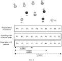
- FIG. 3 is a schematic diagram of a process of Morton order-based LOD partition.
- a point cloud to-be-partitioned includes points P0, P1, P2, P3, P4, P5, P6, P7, P8, and P9, where an original point cloud order is P0, P1, P2, P3, P4, P5, P6, P7, P8, and P9.
- the points listed in ascending Morton order are: P4, P1, P9, P5, P0, P6, P8, P2, P7, and P3.
- LOD0 obtained by the above Morton order-based LOD partition method includes P4, P5, P0, and P1, LOD1 includes P4, P5, P0, P1, P3, P2, and P6, and LOD2 includes P4, P5, P0, P1, P3, P2, P6, P7, P8, and P9.
- the distance-based LOD partition method searches within a range of the Morton code corresponding to the current point, calculates spatial geometric distances from points in the range to the current point, and comparing the distances with a threshold. Until the distances of all points are greater than the threshold, the current point is added to the current LOD layer. Otherwise, the current point is left to the next layer for partition.
- the test data obtained through testing shows that the time used by the distance-based LOD partition method occupies about 70% ⁇ 90% of the total coding time. Obviously, the computational complexity is high.
- the point cloud is partitioned into LODs based on distance. Since there is a great correlation between attributes of adjacent points in the space, the LOD-based structure can be used to predict the attributes of adjacent nodes, so as to remove attribute redundancy between adjacent points. However, since different point clouds have different spatial distributions, the object densities of different point clouds are different. Therefore, in the LOD partition process based on distance in the related art, the neighbor points obtained by searching based on uniform distribution of the point cloud (equivalent to the distance thresholds for partition are the same) are not accurate enough, resulting in large prediction residuals and low coding efficiency.
- the method of searching within a range of Morton code corresponding to the current point is used on a basic of distance-based LOD partition.
- the LOD partition structure is required to predict attributes of neighbor nodes. Since different point clouds have different spatial distributions, the object densities of different point clouds are different. Therefore, the LOD partition structure obtained through the partition method cannot accurately predict neighbor nodes, resulting in large prediction residuals and low coding efficiency. As can be seen, the LOD layers obtained through the current LOD partition method lead to a low prediction accuracy of neighbor nodes.
- FIG. 4 is a schematic flowchart of an optional partition method provided in implementations of this application. As illustrated in FIG. 4 , the method can be applied to an encoder or a decoder.
- the partition method includes the following.
- the partition method provided in implementations of this application improves the generation process of LODs in lifting and predicting attribute transform and applies to the encoder and the decoder.
- the method partitions the LOD structure using this improved technology before lifting or predicting transform. This method applies in the block of generating LOD in FIG. 1 .
- the Morton codes for the point cloud to-be-partitioned is first calculated.
- spatial position relationship between points can be known with the Morton codes, which facilitates to predict neighbor nodes after partition of LOD layers.
- the point cloud to-be-partitioned is determined as an input point cloud of a first iteration.
- the point cloud to-be-partitioned is obtained, which includes at least two points, such as 10 points.
- the point cloud to-be-partitioned is determined as the input point cloud of the first iteration.
- the method may include the following before S402.
- the Morton codes for the point cloud to-be-partitioned are shifted right by N bits and points with a same value of Morton codes after right shifted by N bits are grouped into a point cloud group, where N is a positive integer.
- Each point cloud group is determined as the input point cloud of the first iteration respectively.
- the point cloud to-be-partitioned is not directly used as the input point cloud of the first iteration. Instead, the Morton codes for the point cloud to-be-partitioned is first calculated and then right shifted by N bits. In this way, the points with the same value of Morton codes after right shifted by N bits are adjacent spatially. Therefore, the points with the same value of Morton codes after right shifted by N bits are grouped into a point cloud group and each point cloud group is determined as the input point cloud of the first iteration respectively.
- the point cloud to-be-partitioned is divided into groups and each point cloud group is used as the input point cloud of the first iteration respectively for iterative calculation. Finally, LOD layers after partition of each point cloud group are obtained, such that LOD layers after partition of the point cloud to-be-partitioned are obtained.
- iteration times are indexed with i , where i is a positive integer with an initial value equal to 1.
- Morton codes for the input point cloud of the i -th iteration are shifted right by K bits based on a determination that the number of points in the input point cloud of the i -th iteration is unequal to 0.
- the i -th iteration needs to proceed.
- the points can be ranked in an ascending order of Morton codes so as to better obtain spatial relationships between the points through the Morton codes.
- K is a positive integer.
- the value of K herein may be a fixed value obtained through training, or may be a value obtained by any of the following methods, which is not specifically limited in implementations of the this application.
- the method may further include the following before S404.
- the value of K is determined according to a distribution of the point cloud to-be-partitioned.
- the value of K is determined according to the distribution of the point cloud to-be-partitioned.
- the Morton codes are right shifted by K bit at each iteration, so that the spatial distribution of the point cloud is considered in right-shifting of the Morton codes, which can achieve a better prediction effect.
- the method may further include the following before S404.
- the value of K is determined according to a number of points in the input point cloud of the i- th iteration and a distribution of the input point cloud of the i -th iteration.
- the value of K of each iteration can be determined according to the number of points in the input point cloud of each iteration and the distribution of the input point cloud of each iteration. In this way, for the number of bits of right-shifting of the Morton codes at each iteration, the number of points and the spatial distribution of the point cloud are considered, which can achieve a better prediction effect.
- a point is selected from points with a same value of Morton codes after right shifted by K bits.
- the points with the same value of Morton codes after right shifted by K bits are found, such that at least one group of points with the same value of Morton codes after right shifted by K bits is obtained. Then a point is selected from points with the same value of Morton codes after right shifted by K bits. Any point or a specified point may be selected, which is not specifically limited in implementations of this application.
- S405 may include the following.
- Points in the input point cloud of the i -th iteration are ranked in an ascending order of Morton codes for the input point cloud of the i -th iteration.
- a point ranked first is selected from the points with the same value of Morton codes after right shifted by K bits.
- the points are ranked in an ascending order of Morton codes and the points with the same value of Morton codes after right shifted by K bits are found, such that at least one group of points with the same value of Morton codes after right shifted by K bits is obtained. Thereafter, the first point is selected from each group, where the first point is the point ranked first in an original point cloud order among the points with the same value of Morton codes after right shifted by K bits.
- S405 may include the following.
- a center of mass of the points with the same value of Morton codes after right shifted by K bits is determined. From the points with the same value of Morton codes after right shifted by K bits, a point closest to the center of mass is determined as the point selected.
- the center of mass of the points with the same value of Morton codes after right shifted by K bits is first determined, where the center of mass is calculated according to 3D coordinates of each point in the input point cloud of this iteration. After the center of mass is obtained, the point closest to the center of mass is calculated from the points with the same value of Morton codes after right shifted by K bits, and the point is selected.
- the method may further include the following after S404 and before S406.
- a corresponding selection number is determined according to a number of points with the same value of Morton codes after right shifted by K bits. From the points with the same value of Morton codes after right shifted by K bits, the selection number of points are selected according to the corresponding selection number.
- more than one point can be selected from the points with the same value of Morton codes after right shifted by K bits.
- the corresponding selection number can be first determined according to the number of points with the same value of Morton codes after right shifted by K bits. For example, the number of points with the same value of Morton codes after right shifted by K bits may be 10, 8, 6, 4, etc.
- the corresponding selection number can be determined according to the number of points with the same value of Morton codes. For instance, if the number of points with the same value of Morton codes after right shifted by K bits is 10, the corresponding selection number may be 5. If the number of points with the same value of Morton codes after right shifted by K bits is 8, the corresponding selection number may be 4.
- the corresponding selection number may be 3. If the number of points with the same value of Morton codes after right shifted by K bits is 4, the corresponding selection number may be 2. That is, the corresponding selection number can be determined according to a proportional relationship.
- the selection number of points are selected from the points with the same value of Morton codes after right shifted by K bits according to the selection number.
- the selection number of points may be selected arbitrarily or in a specified manner, which is not specifically limited in implementations of this application.
- the method may further include the following after S404 and before S406.
- Points in the input point cloud of the i -th iteration are ranked in an ascending order of Morton codes for the input point cloud of the i -th iteration. From the points with the same value of Morton codes after right shifted by K bits, a point is selected every second preset threshold according to a ranking result.
- the points are first ranked in an ascending order of Morton codes to obtain the ranking result of the input point cloud of the i -th iteration. Then the points with the same value of Morton codes after right shifted by K bits are found. Since each group of points with the same value of Morton codes after right shifted by K bits are also listed according to the ranking result, one point is selected every second preset threshold to obtained selected points.
- the second preset threshold is a value set as need.
- an i -th LOD layer is formed with the point selected, remaining points other than the point selected in the input point cloud of the i -th iteration are determined as an input point cloud of an ( i +1)-th iteration, i is updated to i +1, and return to S403.
- the LOD layer of this iteration (that is, the i -th LOD layer) is formed with the selected point. Therefore, after this iteration, some points in the input point cloud of this iteration are partitioned into the LOD layer, while the remaining points other than the point selected in the input point cloud of this iteration are determined as the input point cloud of the ( i +1)-th iteration. Then i is updated to i +1, and S403 is performed again.
- points adjacent in space can be found by calculating the Morton codes for the input point cloud of the i -th iteration and shifting the Morton codes right by certain bits.
- One or more points are selected from each group of adjacent points to form the LOD layer.
- spatial distribution of the point cloud can be taken into consideration for the partitioned LOD layers, which facilitates to improve the prediction accuracy of neighbor nodes.
- a first to ( i -1)-th LOD layers are determined as LOD layers after partition of the point cloud to-be-partitioned based on a determination that the number of points in the input point cloud of the i -th iteration is equal to 0.
- the iteration may end, and the first to ( i -1)-th LOD layers are determined as LOD layers after partition of the point cloud to-be-partitioned.
- the method may further include the following.
- a LOD layer is obtained by partitioning using a preset distance-based LOD partition algorithm according to the input point cloud of the i -th iteration.
- the LOD layer obtained by partition and the first to ( i -1)-th LOD layers are determined as LOD layers after partition of the point cloud to-be-partitioned.
- the distance-based LOD partition algorithm or a fixed sampling rate-based LOD partition algorithm may be used for partition to obtain LOD layers, which is not specifically limited in implementations of this application.
- the preset distance-based LOD partition algorithm or the fixed sampling rate-based LOD partition algorithm may be invoked to partition the input point cloud of the i -th iteration to obtain the LOD layer.
- the first to ( i -1)-th LOD layers previously obtained and the LOD layer obtained by partition are determined as the LOD layers after partition of the point cloud to-be-partitioned.
- FIG. 5 is a schematic flowchart of an example of an optional partition method provided in implementations of this application.
- the partition method may be applied to an encoder or a decoder.
- the partition method is applied to the encoder.
- the partition method may include the following.
- the point cloud to-be-encoded contains N points each denoted as P[i].
- the Morton codes for the point cloud to-be-encoded are ranked in an ascending order.
- the Morton codes are right shifted by K bits.
- the Morton codes corresponding to points in adjacent positions in space will be equal, because the points adjacent in terms of Morton codes are generally in adjacent positions in the geometric space.
- the points adjacent in the space are clustered together by shifting the Morton codes of all points in the point cloud to-be-encoded in space right by K bits.
- the points with the same value of Morton code after right shifted by K bits at S502 are sampled.
- a point is selected from the set of points clustered together at each iteration.
- Reconstructed attribute values of predicted points are obtained by using attributes of predicting points to perform weighted average on attributes of predicted points based on spatial distances.
- attribute residuals of the predicted points are obtained using the reconstructed attribute values and original attribute values.
- Attributes of neighbor points are predicted using the reconstructed attribute values and predicting residuals. Prediction is perform after each sampling. Thereafter, a final prediction is obtained by combining each prediction, so as to predict attributes of neighbor points remained in the point cloud to-be-encoded.
- the sampling point is assigned as a point in a current LOD layer.
- the sampling point obtained at S503 is assigned as the point in the current LOD layer, and other remaining points are assigned as points in LOD layers higher than the current LOD layer.
- the first point in the points with the same value of Morton codes after right shifted by K bits can be assigned as the sampling point.
- LODs are partitioned using spatial distribution and spatial distances of the point cloud by right shifting Morton codes.
- the number of sampling points will be reduced in a denser part of the point cloud, while the number of sampling points will be increased in a sparser part.
- the attribute residuals between adjacent points are generally large during prediction.
- the prediction residual obtained by the attribute prediction based on the neighbors will be very large, which will lead to a large attribute bit stream after compression, and will degrade the performance of the attribute after reconstruction.
- the corresponding Morton code values of adjacent points are very different. Therefore, when the Morton codes are shifted to the right, there will be few points in this part clustered into one class, so that more sampling points will be obtained. In this way, in prediction based on neighbor attributes, a better prediction effect can be obtained compared to the original scheme that only considers geometric space distances.
- Table 1 Point cloud file Initial number of right shifted bits BD-rate ( attribute ) Time U V Encoding time ratio Decoding time ration frog_00067_vox12 6 -7.4% -16.6% 95% 89% facade_00064_vox11 6 13.3% -4.5% 96% 86% house_without_roof_vox12 6 -3.4% -3.3% 88% 78% Average(average gain) 6 -0.8% -8.1% 93% 84%
- the BD-rate of the reconstructed point cloud is also significantly improved.
- Peak signal to noise ratio (PSNR) is an objective standard for image evaluation. The larger the PSNR, the better the image quality.
- BD-rate is a parameter used to measure the quality of performance. When BD-rate is negative, it means that the performance becomes better. On this basis, the larger the absolute value of BD-rate, the greater the performance gain.
- the partition method provided in implementations of this application reduces the time required for partitioning LODs, thereby reducing the coding time.
- Implementations of this application provide a partition method.
- the method includes the following.
- a point cloud to-be-partitioned is obtained and Morton codes for the point cloud to-be-partitioned are calculated.
- the point cloud to-be-partitioned is determined as an input point cloud of a first iteration.
- a number of points in an input point cloud of the i -th iteration is equal to 0 is determined, where i is a positive integer with an initial value equal to 1.
- Morton codes for the input point cloud of the i -th iteration are right shifted by K bits, where K is a positive integer.
- a point is selected from points with a same value of Morton codes after right shifted by K bits.
- An i -th LOD layer is formed with the point selected, remaining points other than the point selected in the input point cloud of the i -th iteration are determined as an input point cloud of an ( i +1)-th iteration, i is updated to i +1, and return to determine whether the number of points in the input point cloud of the i -th iteration is equal to 0 at the i -th iteration. Based on a determination that the number of points in the input point cloud of the i -th iteration is equal to 0, a first to ( i -1)-th LOD layers are determined as LOD layers after partition of the point cloud to-be-partitioned.
- Morton codes for the input point cloud of each iteration are right shifted by K bits. Thereafter, a point is selected from the points with the same value of Morton codes after right shifted by K bits, and the selected point forms the LOD layer of the current iteration.
- the partition method since points adjacent in Morton codes are generally adjacent in geometric space, the distribution of the point cloud and the spatial distances between points in the point cloud can be comprehensively considered in the LOD partition process by right shifting the Morton codes and selecting the point(s) based on the right-shifted Morton codes.
- the partition of LOD layers obtained is based on the distribution of the point cloud and the spatial distances between points in the point cloud. In this way, the prediction accuracy of neighbor nodes based on LOD layers can be improved, thereby improving the coding efficiency.
- FIG. 6 is a schematic structural diagram of an optional encoder provided in implementations of this application.
- the encoder includes a first calculating module 61, a first determining module 62, a first judging module 63, a first right shifting module 64, a first selecting module 65, a first partitioning module 66, and a second determining module 67.
- the first calculating module 61 is configured to obtain a point cloud to-be-partitioned and calculate Morton codes for the point cloud to-be-partitioned.
- the first determining module 62 is configured to determine the point cloud to-be-partitioned as an input point cloud of a first iteration.
- the first judging module 63 is configured to determine whether a number of points in an input point cloud of an i -th iteration is equal to 0 at the i -th iteration, where i is a positive integer with an initial value equal to 1.
- the first right shifting module 64 is configured to shift Morton codes for the input point cloud of the i -th iteration right by K bits based on a determination that the number of points in the input point cloud of the i -th iteration is unequal to 0, where K is a positive integer.
- the first selecting module 65 is configured to select a point from points with a same value of Morton codes after right shifted by K bits.
- the first partitioning module 66 is configured to form an i -th LOD layer with the point selected, determine remaining points in the input point cloud of the i -th iteration other than the point selected as an input point cloud of an ( i +1)-th iteration, update i to i +1, and return to the first judging module 63 to determine whether the number of points in the input point cloud of the i -th iteration is equal to 0 at the i -th iteration.
- the second determining module 67 is configured to determine a first to ( i -1)-th LOD layers as LOD layers after partition of the point cloud to-be-partitioned based on a determination that the number of points in the input point cloud of the i -th iteration is equal to 0.
- the first determining module 62 may be further configured to determine a value of K according to a distribution of the point cloud to-be-partitioned prior to shifting the Morton codes for the input point cloud of the i -th iteration right by K bits based on the determination that the number of points in the input point cloud of the i -th iteration is unequal to 0.
- the first determining module 62 may be further configured to determine a value of K according to a number of points in the input point cloud of the i -th iteration and a distribution of the input point cloud of the i -th iteration prior to shifting the Morton codes for the input point cloud of the i -th iteration right by K bits based on the determination that the number of points in the input point cloud of the i -th iteration is unequal to 0.
- the encoder may be further configured to obtain a LOD layer by partitioning using a preset distance-based LOD partition algorithm according to the input point cloud of the i -th iteration, and determine the LOD layer obtained by partition and the first to ( i -1)-th LOD layers as LOD layers after partition of the point cloud to-be-partitioned.
- the first selecting module 65 may be specifically configured to rank points in the input point cloud of the i -th iteration in an ascending order of Morton codes for the input point cloud of the i -th iteration, and select a point ranked first from the points with the same value of Morton codes after right shifted by K bits.
- the first selecting module 65 may be specifically configured to determine a center of mass of the points with the same value of Morton codes after right shifted by K bits, and determine, from the points with the same value of Morton codes after right shifted by K bits, a point closest to the center of mass as the point selected.
- the first selecting module 65 may be specifically configured to determine a corresponding selection number according to a number of points with the same value of Morton codes after right shifted by K bits, and select, from the points with the same value of Morton codes after right shifted by K bits, the selection number of points according to the corresponding selection number.
- the first selecting module 65 may be specifically configured to rank points in the input point cloud of the i -th iteration in an ascending order of Morton codes for the input point cloud of the i -th iteration, and select, from the points with the same value of Morton codes after right shifted by K bits, a point every second preset threshold according to a ranking result.
- the first determining module 62 may be further configured to shift the Morton codes for the point cloud to-be-partitioned right by N bits and group points with the same value of Morton codes after right shifted by N bits into a point cloud group, and determine each point cloud group as the input point cloud of the first iteration respectively, where N is a positive integer.
- FIG. 7 is a schematic structural diagram of an optional decoder provided in implementations of this application.
- the decoder includes a second calculating module 71, a third determining module 72, a second judging module 73, a second right shifting module 74, a second selecting module 75, a second partitioning module 76, and a fourth determining module 77.
- the second calculating module 71 is configured to obtain a point cloud to-be-partitioned and calculate Morton codes for the point cloud to-be-partitioned.
- the third determining module 72 is configured to determine the point cloud to-be-partitioned as an input point cloud of a first iteration.
- the second judging module 73 is configured to determine whether a number of points in an input point cloud of an i -th iteration is equal to 0 at the i -th iteration, where i is a positive integer with an initial value equal to 1.
- the second right shifting module 74 is configured to shift Morton codes for the input point cloud of the i -th iteration right by K bits based on a determination that the number of points in the input point cloud of the i -th iteration is unequal to 0, where K is a positive integer.
- the second selecting module 75 is configured to select a point from points with a same value of Morton codes after right shifted by K bits.
- the second partitioning 76 module is configured to form an i -th LOD layer with the point selected, determine remaining points in the input point cloud of the i -th iteration other than the point selected as an input point cloud of an ( i +1)-th iteration, update i to i +1, and return to the first judging module 63 to determine whether the number of points in the input point cloud of the i -th iteration is equal to 0 at the i -th iteration.
- the fourth determining module 77 is configured to determine a first to ( i -1)-th LOD layers as LOD layers after partition of the point cloud to-be-partitioned based on a determination that the number of points in the input point cloud of the i -th iteration is equal to 0.
- the third determining module 72 may be further configured to determine a value of K according to a distribution of the point cloud to-be-partitioned prior to shifting the Morton codes for the input point cloud of the i -th iteration right by K bits based on the determination that the number of points in the input point cloud of the i -th iteration is unequal to 0.
- the third determining module 72 may be further configured to determine a value of K according to a number of points in the input point cloud of the i -th iteration and a distribution of the input point cloud of the i -th iteration prior to shifting the Morton codes for the input point cloud of the i -th iteration right by K bits based on the determination that the number of points in the input point cloud of the i -th iteration is unequal to 0.
- the decoder may be further configured to obtain a LOD layer by partitioning using a preset distance-based LOD partition algorithm according to the input point cloud of the i -th iteration, and determine the LOD layer obtained by partition and the first to ( i -1)-th LOD layers as LOD layers after partition of the point cloud to-be-partitioned.
- the second selecting module 75 may be specifically configured to rank points in the input point cloud of the i -th iteration in an ascending order of Morton codes for the input point cloud of the i -th iteration, and select a point ranked first from the points with the same value of Morton codes after right shifted by K bits.
- the second selecting module 75 may be specifically configured to determine a center of mass of the points with the same value of Morton codes after right shifted by K bits, and determine, from the points with the same value of Morton codes after right shifted by K bits, a point closest to the center of mass as the point selected.
- the second selecting module 75 may be specifically configured to determine a corresponding selection number according to a number of points with the same value of Morton codes after right shifted by K bits, and select, from the points with the same value of Morton codes after right shifted by K bits, the selection number of points according to the corresponding selection number.
- the second selecting module 75 may be specifically configured to rank points in the input point cloud of the i -th iteration in an ascending order of Morton codes for the input point cloud of the i -th iteration, and select, from the points with the same value of Morton codes after right shifted by K bits, a point every second preset threshold according to a ranking result.
- the third determining module 72 may be further configured to shift the Morton codes for the point cloud to-be-partitioned right by N bits and group points with the same value of Morton codes after right shifted by N bits into a point cloud group, and determine each point cloud group as the input point cloud of the first iteration respectively, where N is a positive integer.
- FIG. 8 is a schematic structural diagram of another optional encoder provided in implementations of this application.
- the encoder 800 proposed in the implementations of this application may further include a processor 81 and a storage medium 82 storing instructions executable by the processor 81.
- the storage medium 82 relies on the processor 81 to perform operations through the communication bus 83.
- the partition method described in one or more of the above implementations is executed.
- the communication bus 83 is configured to realize connection and communication between these components.
- the communication bus 83 also includes a power bus, a control bus, and a status signal bus.
- the various buses are designated as communication bus 83 in FIG. 8 .
- FIG. 9 is a schematic structural diagram of an optional decoder provided in implementations of this application.
- the decoder 900 proposed in the implementations of this application may further include a processor 91 and a storage medium 92 storing instructions executable by the processor 91.
- the storage medium 92 relies on the processor 91 to perform operations through the communication bus 93.
- the partition method described in one or more of the above implementations is executed.
- the communication bus 93 is configured to realize connection and communication between these components.
- the communication bus 93 also includes a power bus, a control bus, and a status signal bus.
- the various buses are designated as communication bus 93 in FIG. 9 .
- Implementations of this application provide a computer storage medium storing executable instructions, and when the executable instructions are executed by one or more processors, the processors execute the partition method described in one or more of the foregoing implementations.
- the memory in implementations of this application may be a volatile memory or a non-volatile memory, or may include both volatile and non-volatile memory.
- the non-volatile memory may be a read-only memory (ROM), a programmable read-only memory (PROM), an erasable programmable read-only memory (EPROM), an electrically erasable programmable read-only memory (Electrically EPROM, EEPROM), or a flash memory.
- the volatile memory may be a random access memory (RAM), which acts as an external cache.
- RAM static RAM
- DRAM dynamic RAM
- SDRAM synchronous DRAM
- DDRSDRAM double data rate synchronous dynamic random access memory
- Enhanced SDRAM ESDRAM
- Synchlink DRAM SLDRAM
- direct rambus RAM DRRAM
- the processor may be an integrated circuit chip with signal processing capabilities.
- each step of the above-mentioned method can be completed by a hardware integrated logic circuit in a processor or an instruction in the form of software.
- the above-mentioned processor may be a general-purpose processor, a digital signal processor (DSP), an application specific integrated circuit (ASIC), a field programmable gate array (FPGA), or other programmable logic devices, discrete gate or transistor logic devices, discrete hardware components.
- DSP digital signal processor
- ASIC application specific integrated circuit
- FPGA field programmable gate array
- the methods, steps, and logic block diagrams disclosed in the implementations of this application can be implemented or executed.
- the general purpose processor may be a microprocessor or the processor may be any conventional processor or the like.
- the steps of the method disclosed in conjunction with the implementations of this application may be directly embodied as executed by a hardware coding processor, or executed by a combination of hardware and software modules in the coding processor.
- the software modules may be located in random access memory, flash memory, read-only memory, programmable read-only memory or electrically erasable programmable memory, registers and other storage media mature in the art.
- the storage medium is located in the memory, and the processor reads the information in the memory, and completes the steps of the above method in combination with its hardware.
- the implementations described herein may be implemented in hardware, software, firmware, middleware, microcode, or a combination thereof.
- the processing unit can be implemented in one or more ASICs, DSPs, DSP devices (DSPDs), programmable logic devices (PLDs), FPGAs, general purpose processors, controllers, microcontrollers, microprocessors, other electronic units for performing the functions described in this application, or a combination thereof.
- the techniques described herein may be implemented through modules (e.g., procedures, functions, etc.) that perform the functions described herein.
- Software codes may be stored in memory and executed by a processor.
- the memory can be implemented in the processor or external to the processor.
- Implementations of this application provide a partition method, an encoder, a decoder, and a computer storage medium.
- a point cloud to-be-partitioned is obtained and Morton codes for the point cloud to-be-partitioned are calculated.
- the point cloud to-be-partitioned is determined as an input point cloud of a first iteration. At an i -th iteration, whether a number of points in an input point cloud of the i -th iteration is equal to 0 is determined, where i is a positive integer with an initial value equal to 1.
- Morton codes for the input point cloud of the i -th iteration are right shifted by K bits, where K is a positive integer.
- a point is selected from points with a same value of Morton codes after right shifted by K bits.
- An i -th level of detail (LOD) layer is formed with the point selected, remaining points other than the point selected in the input point cloud of the i -th iteration are determined as an input point cloud of an ( i +1)-th iteration, i is updated to i +1, and return to determine whether the number of points in the input point cloud of the i -th iteration is equal to 0 during the i -th iteration.
- a first to ( i -1)-th LOD layers are determined as LOD layers after partition of the point cloud to-be-partitioned. As such, a prediction accuracy of neighbor nodes based on LOD layers can be improved, thereby improving coding efficiency.
Landscapes
- Engineering & Computer Science (AREA)
- Multimedia (AREA)
- Physics & Mathematics (AREA)
- Signal Processing (AREA)
- General Physics & Mathematics (AREA)
- Theoretical Computer Science (AREA)
- Computer Vision & Pattern Recognition (AREA)
- Software Systems (AREA)
- Geometry (AREA)
- Computer Graphics (AREA)
- Compression, Expansion, Code Conversion, And Decoders (AREA)
- Image Generation (AREA)
- Compression Or Coding Systems Of Tv Signals (AREA)
- Error Detection And Correction (AREA)
- Image Analysis (AREA)
- Signal Processing For Digital Recording And Reproducing (AREA)
Applications Claiming Priority (1)
| Application Number | Priority Date | Filing Date | Title |
|---|---|---|---|
| PCT/CN2019/109653 WO2021062736A1 (zh) | 2019-09-30 | 2019-09-30 | 划分方法、编码器、解码器以及计算机存储介质 |
Publications (3)
| Publication Number | Publication Date |
|---|---|
| EP4040393A1 true EP4040393A1 (de) | 2022-08-10 |
| EP4040393A4 EP4040393A4 (de) | 2023-06-14 |
| EP4040393B1 EP4040393B1 (de) | 2024-11-06 |
Family
ID=75336664
Family Applications (1)
| Application Number | Title | Priority Date | Filing Date |
|---|---|---|---|
| EP19947936.1A Active EP4040393B1 (de) | 2019-09-30 | 2019-09-30 | Teilungsverfahren, codierer, decodierer und computerspeichermedium |
Country Status (6)
| Country | Link |
|---|---|
| US (3) | US11483560B2 (de) |
| EP (1) | EP4040393B1 (de) |
| JP (1) | JP7386337B2 (de) |
| KR (1) | KR102692779B1 (de) |
| CN (2) | CN114820831B (de) |
| WO (1) | WO2021062736A1 (de) |
Cited By (1)
| Publication number | Priority date | Publication date | Assignee | Title |
|---|---|---|---|---|
| EP4083924A4 (de) * | 2020-01-06 | 2023-02-22 | Guangdong Oppo Mobile Telecommunications Corp., Ltd. | Suchverfahren für nächsten nachbarn, vorrichtung, gerät und speichermedium |
Families Citing this family (9)
| Publication number | Priority date | Publication date | Assignee | Title |
|---|---|---|---|---|
| WO2021062736A1 (zh) * | 2019-09-30 | 2021-04-08 | Oppo广东移动通信有限公司 | 划分方法、编码器、解码器以及计算机存储介质 |
| WO2021138785A1 (zh) | 2020-01-06 | 2021-07-15 | Oppo广东移动通信有限公司 | 划分方法、编码器、解码器及计算机存储介质 |
| US12244866B2 (en) * | 2020-03-11 | 2025-03-04 | Lg Electronics Inc. | Device for transmitting point cloud data, method for transmitting point cloud data, device for receiving point cloud data, and method for receiving point cloud data |
| US11816868B2 (en) * | 2020-08-14 | 2023-11-14 | Tencent America LLC | Coding of multiple-component attributes for point cloud coding |
| CN113341396B (zh) * | 2021-05-28 | 2023-12-15 | 深圳市优必选科技股份有限公司 | 机器人及其充电桩识别方法和装置 |
| CN117730539A (zh) * | 2021-07-14 | 2024-03-19 | Lg 电子株式会社 | 点云数据发送设备和方法以及点云数据接收设备和方法 |
| WO2023287214A1 (ko) * | 2021-07-14 | 2023-01-19 | 엘지전자 주식회사 | 포인트 클라우드 데이터 송신 장치, 포인트 클라우드 데이터 송신 방법, 포인트 클라우드 데이터 수신 장치 및 포인트 클라우드 데이터 수신 방법 |
| CN115720273A (zh) * | 2021-08-24 | 2023-02-28 | 腾讯科技(深圳)有限公司 | 点云编解码中的属性预测方法、装置、设备及存储介质 |
| EP4465636A4 (de) * | 2022-01-12 | 2025-11-26 | Lg Electronics Inc | Punktwolkendatenübertragungsverfahren, punktwolkendatenübertragungsvorrichtung, punktwolkendatenempfangsverfahren und punktwolkendatenempfangsvorrichtung |
Family Cites Families (14)
| Publication number | Priority date | Publication date | Assignee | Title |
|---|---|---|---|---|
| US7940279B2 (en) * | 2007-03-27 | 2011-05-10 | Utah State University | System and method for rendering of texel imagery |
| CN102436654B (zh) * | 2011-09-02 | 2013-07-10 | 清华大学 | 建筑点云的自适应分割方法 |
| CN103077549B (zh) * | 2012-10-24 | 2016-12-21 | 华南理工大学 | 一种基于kd树的实时大规模地形可视化实现方法 |
| US20150113379A1 (en) * | 2013-10-23 | 2015-04-23 | Schlumberger Technology Corporation | Representation of unstructured grids |
| FR3035990A1 (fr) * | 2015-05-07 | 2016-11-11 | Inst Mines Telecom | Procede de simplification de modele de geometrie |
| US10897269B2 (en) * | 2017-09-14 | 2021-01-19 | Apple Inc. | Hierarchical point cloud compression |
| US10861196B2 (en) * | 2017-09-14 | 2020-12-08 | Apple Inc. | Point cloud compression |
| US10853447B2 (en) * | 2018-01-19 | 2020-12-01 | 8i Limited | Bezier volume representation of point cloud attributes |
| CN108470374B (zh) * | 2018-04-08 | 2022-03-25 | 中煤航测遥感集团有限公司 | 海量点云数据处理方法及装置 |
| CN109257604B (zh) * | 2018-11-20 | 2020-11-27 | 山东大学 | 一种基于tmc3点云编码器的颜色属性编码方法 |
| CN109886272B (zh) * | 2019-02-25 | 2020-10-30 | 腾讯科技(深圳)有限公司 | 点云分割方法、装置、计算机可读存储介质和计算机设备 |
| CN109889840B (zh) * | 2019-03-20 | 2022-11-22 | 北京大学深圳研究生院 | 点云编码和解码的方法、编码设备和解码设备 |
| CN114424568A (zh) * | 2019-09-30 | 2022-04-29 | Oppo广东移动通信有限公司 | 预测方法、编码器、解码器及计算机存储介质 |
| WO2021062736A1 (zh) * | 2019-09-30 | 2021-04-08 | Oppo广东移动通信有限公司 | 划分方法、编码器、解码器以及计算机存储介质 |
-
2019
- 2019-09-30 WO PCT/CN2019/109653 patent/WO2021062736A1/zh not_active Ceased
- 2019-09-30 CN CN202210356934.3A patent/CN114820831B/zh active Active
- 2019-09-30 KR KR1020227011834A patent/KR102692779B1/ko active Active
- 2019-09-30 JP JP2022519645A patent/JP7386337B2/ja active Active
- 2019-09-30 EP EP19947936.1A patent/EP4040393B1/de active Active
- 2019-09-30 CN CN201980098780.9A patent/CN114207668A/zh active Pending
-
2022
- 2022-03-23 US US17/702,674 patent/US11483560B2/en active Active
- 2022-09-12 US US17/931,272 patent/US11785216B2/en active Active
-
2023
- 2023-08-15 US US18/449,874 patent/US12289448B2/en active Active
Cited By (1)
| Publication number | Priority date | Publication date | Assignee | Title |
|---|---|---|---|---|
| EP4083924A4 (de) * | 2020-01-06 | 2023-02-22 | Guangdong Oppo Mobile Telecommunications Corp., Ltd. | Suchverfahren für nächsten nachbarn, vorrichtung, gerät und speichermedium |
Also Published As
| Publication number | Publication date |
|---|---|
| US11785216B2 (en) | 2023-10-10 |
| WO2021062736A1 (zh) | 2021-04-08 |
| CN114207668A (zh) | 2022-03-18 |
| US20230388497A1 (en) | 2023-11-30 |
| CN114820831A (zh) | 2022-07-29 |
| JP2023500186A (ja) | 2023-01-05 |
| CN114820831B (zh) | 2025-02-25 |
| US11483560B2 (en) | 2022-10-25 |
| US20230007250A1 (en) | 2023-01-05 |
| EP4040393A4 (de) | 2023-06-14 |
| JP7386337B2 (ja) | 2023-11-24 |
| KR20220074892A (ko) | 2022-06-03 |
| US12289448B2 (en) | 2025-04-29 |
| EP4040393B1 (de) | 2024-11-06 |
| KR102692779B1 (ko) | 2024-08-08 |
| US20220217343A1 (en) | 2022-07-07 |
Similar Documents
| Publication | Publication Date | Title |
|---|---|---|
| EP4040393B1 (de) | Teilungsverfahren, codierer, decodierer und computerspeichermedium | |
| US20240257404A1 (en) | Methods for level partition of point cloud, and decoder | |
| US11936909B2 (en) | Prediction method, encoder, decoder, and computer storage medium | |
| US20230101072A1 (en) | Nearest neighbour search method, encoder, decoder and storage medium | |
| US12200231B2 (en) | Nearest neighbor search method, apparatus, device, and storage medium | |
| CN115174922B (zh) | 划分方法、编码器、解码器及计算机存储介质 | |
| JP2023523272A5 (de) | ||
| WO2022120594A1 (zh) | 点云编解码方法、编码器、解码器及计算机存储介质 | |
| CN114009014A (zh) | 颜色分量预测方法、编码器、解码器及计算机存储介质 | |
| CN116097650B (zh) | 一种点云数据的层次划分方法、编码器及存储介质 | |
| CN117157973A (zh) | 编解码方法及相关设备、存储介质 | |
| WO2023155045A1 (zh) | 预测的方法和装置、编码器、解码器和编解码系统 |
Legal Events
| Date | Code | Title | Description |
|---|---|---|---|
| STAA | Information on the status of an ep patent application or granted ep patent |
Free format text: STATUS: THE INTERNATIONAL PUBLICATION HAS BEEN MADE |
|
| PUAI | Public reference made under article 153(3) epc to a published international application that has entered the european phase |
Free format text: ORIGINAL CODE: 0009012 |
|
| STAA | Information on the status of an ep patent application or granted ep patent |
Free format text: STATUS: REQUEST FOR EXAMINATION WAS MADE |
|
| 17P | Request for examination filed |
Effective date: 20220328 |
|
| AK | Designated contracting states |
Kind code of ref document: A1 Designated state(s): AL AT BE BG CH CY CZ DE DK EE ES FI FR GB GR HR HU IE IS IT LI LT LU LV MC MK MT NL NO PL PT RO RS SE SI SK SM TR |
|
| DAV | Request for validation of the european patent (deleted) | ||
| DAX | Request for extension of the european patent (deleted) | ||
| A4 | Supplementary search report drawn up and despatched |
Effective date: 20230516 |
|
| RIC1 | Information provided on ipc code assigned before grant |
Ipc: G06T 9/00 20060101ALI20230510BHEP Ipc: H04N 19/169 20140101ALI20230510BHEP Ipc: G06T 9/40 20060101AFI20230510BHEP |
|
| STAA | Information on the status of an ep patent application or granted ep patent |
Free format text: STATUS: EXAMINATION IS IN PROGRESS |
|
| 17Q | First examination report despatched |
Effective date: 20240207 |
|
| REG | Reference to a national code |
Ref country code: DE Ref legal event code: R079 Ref document number: 602019061785 Country of ref document: DE Free format text: PREVIOUS MAIN CLASS: G06T0009400000 Ipc: G06T0007500000 |
|
| GRAP | Despatch of communication of intention to grant a patent |
Free format text: ORIGINAL CODE: EPIDOSNIGR1 |
|
| STAA | Information on the status of an ep patent application or granted ep patent |
Free format text: STATUS: GRANT OF PATENT IS INTENDED |
|
| RIC1 | Information provided on ipc code assigned before grant |
Ipc: G06T 9/00 20060101ALI20240704BHEP Ipc: G06T 9/40 20060101ALI20240704BHEP Ipc: H04N 19/597 20140101ALI20240704BHEP Ipc: G06T 7/50 20170101AFI20240704BHEP |
|
| INTG | Intention to grant announced |
Effective date: 20240723 |
|
| GRAS | Grant fee paid |
Free format text: ORIGINAL CODE: EPIDOSNIGR3 |
|
| GRAA | (expected) grant |
Free format text: ORIGINAL CODE: 0009210 |
|
| STAA | Information on the status of an ep patent application or granted ep patent |
Free format text: STATUS: THE PATENT HAS BEEN GRANTED |
|
| AK | Designated contracting states |
Kind code of ref document: B1 Designated state(s): AL AT BE BG CH CY CZ DE DK EE ES FI FR GB GR HR HU IE IS IT LI LT LU LV MC MK MT NL NO PL PT RO RS SE SI SK SM TR |
|
| REG | Reference to a national code |
Ref country code: GB Ref legal event code: FG4D |
|
| REG | Reference to a national code |
Ref country code: CH Ref legal event code: EP |
|
| REG | Reference to a national code |
Ref country code: DE Ref legal event code: R096 Ref document number: 602019061785 Country of ref document: DE |
|
| REG | Reference to a national code |
Ref country code: IE Ref legal event code: FG4D |
|
| REG | Reference to a national code |
Ref country code: LT Ref legal event code: MG9D |
|
| REG | Reference to a national code |
Ref country code: NL Ref legal event code: MP Effective date: 20241106 |
|
| P01 | Opt-out of the competence of the unified patent court (upc) registered |
Free format text: CASE NUMBER: APP_9791/2025 Effective date: 20250226 |
|
| PG25 | Lapsed in a contracting state [announced via postgrant information from national office to epo] |
Ref country code: IS Free format text: LAPSE BECAUSE OF FAILURE TO SUBMIT A TRANSLATION OF THE DESCRIPTION OR TO PAY THE FEE WITHIN THE PRESCRIBED TIME-LIMIT Effective date: 20250306 Ref country code: PT Free format text: LAPSE BECAUSE OF FAILURE TO SUBMIT A TRANSLATION OF THE DESCRIPTION OR TO PAY THE FEE WITHIN THE PRESCRIBED TIME-LIMIT Effective date: 20250306 Ref country code: HR Free format text: LAPSE BECAUSE OF FAILURE TO SUBMIT A TRANSLATION OF THE DESCRIPTION OR TO PAY THE FEE WITHIN THE PRESCRIBED TIME-LIMIT Effective date: 20241106 |
|
| PG25 | Lapsed in a contracting state [announced via postgrant information from national office to epo] |
Ref country code: FI Free format text: LAPSE BECAUSE OF FAILURE TO SUBMIT A TRANSLATION OF THE DESCRIPTION OR TO PAY THE FEE WITHIN THE PRESCRIBED TIME-LIMIT Effective date: 20241106 Ref country code: NL Free format text: LAPSE BECAUSE OF FAILURE TO SUBMIT A TRANSLATION OF THE DESCRIPTION OR TO PAY THE FEE WITHIN THE PRESCRIBED TIME-LIMIT Effective date: 20241106 |
|
| REG | Reference to a national code |
Ref country code: AT Ref legal event code: MK05 Ref document number: 1740216 Country of ref document: AT Kind code of ref document: T Effective date: 20241106 |
|
| PG25 | Lapsed in a contracting state [announced via postgrant information from national office to epo] |
Ref country code: BG Free format text: LAPSE BECAUSE OF FAILURE TO SUBMIT A TRANSLATION OF THE DESCRIPTION OR TO PAY THE FEE WITHIN THE PRESCRIBED TIME-LIMIT Effective date: 20241106 |
|
| PG25 | Lapsed in a contracting state [announced via postgrant information from national office to epo] |
Ref country code: ES Free format text: LAPSE BECAUSE OF FAILURE TO SUBMIT A TRANSLATION OF THE DESCRIPTION OR TO PAY THE FEE WITHIN THE PRESCRIBED TIME-LIMIT Effective date: 20241106 |
|
| PG25 | Lapsed in a contracting state [announced via postgrant information from national office to epo] |
Ref country code: NO Free format text: LAPSE BECAUSE OF FAILURE TO SUBMIT A TRANSLATION OF THE DESCRIPTION OR TO PAY THE FEE WITHIN THE PRESCRIBED TIME-LIMIT Effective date: 20250206 |
|
| PG25 | Lapsed in a contracting state [announced via postgrant information from national office to epo] |
Ref country code: GR Free format text: LAPSE BECAUSE OF FAILURE TO SUBMIT A TRANSLATION OF THE DESCRIPTION OR TO PAY THE FEE WITHIN THE PRESCRIBED TIME-LIMIT Effective date: 20250207 Ref country code: LV Free format text: LAPSE BECAUSE OF FAILURE TO SUBMIT A TRANSLATION OF THE DESCRIPTION OR TO PAY THE FEE WITHIN THE PRESCRIBED TIME-LIMIT Effective date: 20241106 Ref country code: AT Free format text: LAPSE BECAUSE OF FAILURE TO SUBMIT A TRANSLATION OF THE DESCRIPTION OR TO PAY THE FEE WITHIN THE PRESCRIBED TIME-LIMIT Effective date: 20241106 |
|
| PG25 | Lapsed in a contracting state [announced via postgrant information from national office to epo] |
Ref country code: PL Free format text: LAPSE BECAUSE OF FAILURE TO SUBMIT A TRANSLATION OF THE DESCRIPTION OR TO PAY THE FEE WITHIN THE PRESCRIBED TIME-LIMIT Effective date: 20241106 |
|
| PG25 | Lapsed in a contracting state [announced via postgrant information from national office to epo] |
Ref country code: RS Free format text: LAPSE BECAUSE OF FAILURE TO SUBMIT A TRANSLATION OF THE DESCRIPTION OR TO PAY THE FEE WITHIN THE PRESCRIBED TIME-LIMIT Effective date: 20250206 |
|
| PG25 | Lapsed in a contracting state [announced via postgrant information from national office to epo] |
Ref country code: SM Free format text: LAPSE BECAUSE OF FAILURE TO SUBMIT A TRANSLATION OF THE DESCRIPTION OR TO PAY THE FEE WITHIN THE PRESCRIBED TIME-LIMIT Effective date: 20241106 |
|
| PG25 | Lapsed in a contracting state [announced via postgrant information from national office to epo] |
Ref country code: DK Free format text: LAPSE BECAUSE OF FAILURE TO SUBMIT A TRANSLATION OF THE DESCRIPTION OR TO PAY THE FEE WITHIN THE PRESCRIBED TIME-LIMIT Effective date: 20241106 |
|
| PG25 | Lapsed in a contracting state [announced via postgrant information from national office to epo] |
Ref country code: EE Free format text: LAPSE BECAUSE OF FAILURE TO SUBMIT A TRANSLATION OF THE DESCRIPTION OR TO PAY THE FEE WITHIN THE PRESCRIBED TIME-LIMIT Effective date: 20241106 |
|
| PG25 | Lapsed in a contracting state [announced via postgrant information from national office to epo] |
Ref country code: RO Free format text: LAPSE BECAUSE OF FAILURE TO SUBMIT A TRANSLATION OF THE DESCRIPTION OR TO PAY THE FEE WITHIN THE PRESCRIBED TIME-LIMIT Effective date: 20241106 |
|
| PG25 | Lapsed in a contracting state [announced via postgrant information from national office to epo] |
Ref country code: SK Free format text: LAPSE BECAUSE OF FAILURE TO SUBMIT A TRANSLATION OF THE DESCRIPTION OR TO PAY THE FEE WITHIN THE PRESCRIBED TIME-LIMIT Effective date: 20241106 |
|
| PG25 | Lapsed in a contracting state [announced via postgrant information from national office to epo] |
Ref country code: CZ Free format text: LAPSE BECAUSE OF FAILURE TO SUBMIT A TRANSLATION OF THE DESCRIPTION OR TO PAY THE FEE WITHIN THE PRESCRIBED TIME-LIMIT Effective date: 20241106 |
|
| REG | Reference to a national code |
Ref country code: DE Ref legal event code: R097 Ref document number: 602019061785 Country of ref document: DE |
|
| PG25 | Lapsed in a contracting state [announced via postgrant information from national office to epo] |
Ref country code: SE Free format text: LAPSE BECAUSE OF FAILURE TO SUBMIT A TRANSLATION OF THE DESCRIPTION OR TO PAY THE FEE WITHIN THE PRESCRIBED TIME-LIMIT Effective date: 20241106 |
|
| PLBE | No opposition filed within time limit |
Free format text: ORIGINAL CODE: 0009261 |
|
| STAA | Information on the status of an ep patent application or granted ep patent |
Free format text: STATUS: NO OPPOSITION FILED WITHIN TIME LIMIT |
|
| PGFP | Annual fee paid to national office [announced via postgrant information from national office to epo] |
Ref country code: DE Payment date: 20250923 Year of fee payment: 7 |
|
| 26N | No opposition filed |
Effective date: 20250807 |
|
| PGFP | Annual fee paid to national office [announced via postgrant information from national office to epo] |
Ref country code: IT Payment date: 20250917 Year of fee payment: 7 |
|
| PGFP | Annual fee paid to national office [announced via postgrant information from national office to epo] |
Ref country code: GB Payment date: 20250915 Year of fee payment: 7 |
|
| PGFP | Annual fee paid to national office [announced via postgrant information from national office to epo] |
Ref country code: FR Payment date: 20250915 Year of fee payment: 7 |