EP4040585A1 - Boîtier de module, procédé de fabrication d'un boîtier de module et module de batterie - Google Patents
Boîtier de module, procédé de fabrication d'un boîtier de module et module de batterie Download PDFInfo
- Publication number
- EP4040585A1 EP4040585A1 EP22152401.0A EP22152401A EP4040585A1 EP 4040585 A1 EP4040585 A1 EP 4040585A1 EP 22152401 A EP22152401 A EP 22152401A EP 4040585 A1 EP4040585 A1 EP 4040585A1
- Authority
- EP
- European Patent Office
- Prior art keywords
- cell
- module housing
- stops
- housing
- diameter
- Prior art date
- Legal status (The legal status is an assumption and is not a legal conclusion. Google has not performed a legal analysis and makes no representation as to the accuracy of the status listed.)
- Granted
Links
Images


Classifications
-
- H—ELECTRICITY
- H01—ELECTRIC ELEMENTS
- H01M—PROCESSES OR MEANS, e.g. BATTERIES, FOR THE DIRECT CONVERSION OF CHEMICAL ENERGY INTO ELECTRICAL ENERGY
- H01M10/00—Secondary cells; Manufacture thereof
- H01M10/04—Construction or manufacture in general
- H01M10/0422—Cells or battery with cylindrical casing
-
- H—ELECTRICITY
- H01—ELECTRIC ELEMENTS
- H01M—PROCESSES OR MEANS, e.g. BATTERIES, FOR THE DIRECT CONVERSION OF CHEMICAL ENERGY INTO ELECTRICAL ENERGY
- H01M50/00—Constructional details or processes of manufacture of the non-active parts of electrochemical cells other than fuel cells, e.g. hybrid cells
- H01M50/20—Mountings; Secondary casings or frames; Racks, modules or packs; Suspension devices; Shock absorbers; Transport or carrying devices; Holders
- H01M50/204—Racks, modules or packs for multiple batteries or multiple cells
- H01M50/207—Racks, modules or packs for multiple batteries or multiple cells characterised by their shape
- H01M50/213—Racks, modules or packs for multiple batteries or multiple cells characterised by their shape adapted for cells having curved cross-section, e.g. round or elliptic
-
- H—ELECTRICITY
- H01—ELECTRIC ELEMENTS
- H01M—PROCESSES OR MEANS, e.g. BATTERIES, FOR THE DIRECT CONVERSION OF CHEMICAL ENERGY INTO ELECTRICAL ENERGY
- H01M50/00—Constructional details or processes of manufacture of the non-active parts of electrochemical cells other than fuel cells, e.g. hybrid cells
- H01M50/20—Mountings; Secondary casings or frames; Racks, modules or packs; Suspension devices; Shock absorbers; Transport or carrying devices; Holders
- H01M50/218—Mountings; Secondary casings or frames; Racks, modules or packs; Suspension devices; Shock absorbers; Transport or carrying devices; Holders characterised by the material
- H01M50/22—Mountings; Secondary casings or frames; Racks, modules or packs; Suspension devices; Shock absorbers; Transport or carrying devices; Holders characterised by the material of the casings or racks
-
- H—ELECTRICITY
- H01—ELECTRIC ELEMENTS
- H01M—PROCESSES OR MEANS, e.g. BATTERIES, FOR THE DIRECT CONVERSION OF CHEMICAL ENERGY INTO ELECTRICAL ENERGY
- H01M50/00—Constructional details or processes of manufacture of the non-active parts of electrochemical cells other than fuel cells, e.g. hybrid cells
- H01M50/20—Mountings; Secondary casings or frames; Racks, modules or packs; Suspension devices; Shock absorbers; Transport or carrying devices; Holders
- H01M50/218—Mountings; Secondary casings or frames; Racks, modules or packs; Suspension devices; Shock absorbers; Transport or carrying devices; Holders characterised by the material
- H01M50/22—Mountings; Secondary casings or frames; Racks, modules or packs; Suspension devices; Shock absorbers; Transport or carrying devices; Holders characterised by the material of the casings or racks
- H01M50/227—Organic material
-
- H—ELECTRICITY
- H01—ELECTRIC ELEMENTS
- H01M—PROCESSES OR MEANS, e.g. BATTERIES, FOR THE DIRECT CONVERSION OF CHEMICAL ENERGY INTO ELECTRICAL ENERGY
- H01M50/00—Constructional details or processes of manufacture of the non-active parts of electrochemical cells other than fuel cells, e.g. hybrid cells
- H01M50/20—Mountings; Secondary casings or frames; Racks, modules or packs; Suspension devices; Shock absorbers; Transport or carrying devices; Holders
- H01M50/233—Mountings; Secondary casings or frames; Racks, modules or packs; Suspension devices; Shock absorbers; Transport or carrying devices; Holders characterised by physical properties of casings or racks, e.g. dimensions
-
- H—ELECTRICITY
- H01—ELECTRIC ELEMENTS
- H01M—PROCESSES OR MEANS, e.g. BATTERIES, FOR THE DIRECT CONVERSION OF CHEMICAL ENERGY INTO ELECTRICAL ENERGY
- H01M50/00—Constructional details or processes of manufacture of the non-active parts of electrochemical cells other than fuel cells, e.g. hybrid cells
- H01M50/20—Mountings; Secondary casings or frames; Racks, modules or packs; Suspension devices; Shock absorbers; Transport or carrying devices; Holders
- H01M50/244—Secondary casings; Racks; Suspension devices; Carrying devices; Holders characterised by their mounting method
-
- H—ELECTRICITY
- H01—ELECTRIC ELEMENTS
- H01M—PROCESSES OR MEANS, e.g. BATTERIES, FOR THE DIRECT CONVERSION OF CHEMICAL ENERGY INTO ELECTRICAL ENERGY
- H01M50/00—Constructional details or processes of manufacture of the non-active parts of electrochemical cells other than fuel cells, e.g. hybrid cells
- H01M50/20—Mountings; Secondary casings or frames; Racks, modules or packs; Suspension devices; Shock absorbers; Transport or carrying devices; Holders
- H01M50/249—Mountings; Secondary casings or frames; Racks, modules or packs; Suspension devices; Shock absorbers; Transport or carrying devices; Holders specially adapted for aircraft or vehicles, e.g. cars or trains
-
- H—ELECTRICITY
- H01—ELECTRIC ELEMENTS
- H01M—PROCESSES OR MEANS, e.g. BATTERIES, FOR THE DIRECT CONVERSION OF CHEMICAL ENERGY INTO ELECTRICAL ENERGY
- H01M50/00—Constructional details or processes of manufacture of the non-active parts of electrochemical cells other than fuel cells, e.g. hybrid cells
- H01M50/20—Mountings; Secondary casings or frames; Racks, modules or packs; Suspension devices; Shock absorbers; Transport or carrying devices; Holders
- H01M50/258—Modular batteries; Casings provided with means for assembling
-
- H—ELECTRICITY
- H01—ELECTRIC ELEMENTS
- H01M—PROCESSES OR MEANS, e.g. BATTERIES, FOR THE DIRECT CONVERSION OF CHEMICAL ENERGY INTO ELECTRICAL ENERGY
- H01M50/00—Constructional details or processes of manufacture of the non-active parts of electrochemical cells other than fuel cells, e.g. hybrid cells
- H01M50/20—Mountings; Secondary casings or frames; Racks, modules or packs; Suspension devices; Shock absorbers; Transport or carrying devices; Holders
- H01M50/289—Mountings; Secondary casings or frames; Racks, modules or packs; Suspension devices; Shock absorbers; Transport or carrying devices; Holders characterised by spacing elements or positioning means within frames, racks or packs
- H01M50/291—Mountings; Secondary casings or frames; Racks, modules or packs; Suspension devices; Shock absorbers; Transport or carrying devices; Holders characterised by spacing elements or positioning means within frames, racks or packs characterised by their shape
-
- H—ELECTRICITY
- H01—ELECTRIC ELEMENTS
- H01M—PROCESSES OR MEANS, e.g. BATTERIES, FOR THE DIRECT CONVERSION OF CHEMICAL ENERGY INTO ELECTRICAL ENERGY
- H01M50/00—Constructional details or processes of manufacture of the non-active parts of electrochemical cells other than fuel cells, e.g. hybrid cells
- H01M50/20—Mountings; Secondary casings or frames; Racks, modules or packs; Suspension devices; Shock absorbers; Transport or carrying devices; Holders
- H01M50/289—Mountings; Secondary casings or frames; Racks, modules or packs; Suspension devices; Shock absorbers; Transport or carrying devices; Holders characterised by spacing elements or positioning means within frames, racks or packs
- H01M50/293—Mountings; Secondary casings or frames; Racks, modules or packs; Suspension devices; Shock absorbers; Transport or carrying devices; Holders characterised by spacing elements or positioning means within frames, racks or packs characterised by the material
-
- H—ELECTRICITY
- H01—ELECTRIC ELEMENTS
- H01M—PROCESSES OR MEANS, e.g. BATTERIES, FOR THE DIRECT CONVERSION OF CHEMICAL ENERGY INTO ELECTRICAL ENERGY
- H01M2220/00—Batteries for particular applications
- H01M2220/20—Batteries in motive systems, e.g. vehicle, ship, plane
-
- H—ELECTRICITY
- H01—ELECTRIC ELEMENTS
- H01M—PROCESSES OR MEANS, e.g. BATTERIES, FOR THE DIRECT CONVERSION OF CHEMICAL ENERGY INTO ELECTRICAL ENERGY
- H01M50/00—Constructional details or processes of manufacture of the non-active parts of electrochemical cells other than fuel cells, e.g. hybrid cells
- H01M50/50—Current conducting connections for cells or batteries
- H01M50/502—Interconnectors for connecting terminals of adjacent batteries; Interconnectors for connecting cells outside a battery casing
-
- Y—GENERAL TAGGING OF NEW TECHNOLOGICAL DEVELOPMENTS; GENERAL TAGGING OF CROSS-SECTIONAL TECHNOLOGIES SPANNING OVER SEVERAL SECTIONS OF THE IPC; TECHNICAL SUBJECTS COVERED BY FORMER USPC CROSS-REFERENCE ART COLLECTIONS [XRACs] AND DIGESTS
- Y02—TECHNOLOGIES OR APPLICATIONS FOR MITIGATION OR ADAPTATION AGAINST CLIMATE CHANGE
- Y02E—REDUCTION OF GREENHOUSE GAS [GHG] EMISSIONS, RELATED TO ENERGY GENERATION, TRANSMISSION OR DISTRIBUTION
- Y02E60/00—Enabling technologies; Technologies with a potential or indirect contribution to GHG emissions mitigation
- Y02E60/10—Energy storage using batteries
Definitions
- the present invention relates to a module housing made of an electrically insulating plastic material, a method for producing such a module housing, and a battery module with such a module housing.
- the present invention will be described in the following mainly in connection with traction batteries for vehicles. However, the invention can be used for any application in which battery modules are to be assembled from individual round cells.
- a large number of round cells can be connected in series.
- several round cells connected in parallel can be connected in series.
- the positive pole of the first round cell is always connected to the negative pole of the second round cell.
- the positive poles are arranged centrally on the end faces of the round cells, while the cell cups of the round cells form the negative poles.
- the cell cups of the axially aligned round cells must therefore not touch one another in order to prevent the first round cell from short-circuiting.
- an insulating disc can be conventionally arranged between the round cells.
- the insulating disk can have a hole for the positive pole of the first round cell.
- the insulating pane can, for example, be glued onto at least one of the two round cells.
- round cells arranged in parallel can be kept defined in all spatial directions and, in addition, the cell cups used as the negative pole of round cells connected in series can be electrically insulated from one another in order to prevent short circuits.
- a separate insulator can be dispensed with.
- a module housing made of an electrically insulating plastic material with a foam body made of an electrically insulating foam material is proposed, the foam body having essentially cylindrical receptacles for round cells, the module housing having axial stops for cell cups of the round cells aligned with the receptacles and recesses for positive poles of the round cells .
- a battery module with at least one module housing according to the approach presented here is proposed, with one round cell being arranged in the foam body for each receptacle, with cell cups of the round cells lying against an inside of the stops and positive poles of the round cells are arranged in the recesses, with cell connectors resting on an outside of the stops, which are electrically conductively connected to the positive poles, with the cell connectors being electrically insulated from the cell cups by the stops.
- the mounts for the round cells are essentially cylindrical, ie it is a cylindrical mount, regardless of the usual tolerances.
- a method for producing such a module housing is also proposed, the module housing with the stops and recesses being made from an electrically insulating plastic material and the foam body with the receptacles being foamed from an electrically insulating foam material in a foaming tool.
- a round cell can be a cylindrical battery cell.
- the round cell can have a cell cup that encloses a roll of several electrically active layers.
- the positive pole of the round cell can be arranged in the center or core of the roll.
- the cell cup can form the negative pole of the round cell.
- a battery module can be a combination of many round cells in one housing.
- the battery module can have two connection terminals with which the round cells are electrically connected.
- the round cells can be electrically connected in series between the connection terminals, with at least one positive pole always being connected to at least one negative pole of another round cell.
- the positive poles and negative poles can be connected to one another by the cell connectors.
- the round cells can also be electrically connected in parallel, with the positive poles of at least two round cells being connected to one another and the negative poles of the round cells also being connected to one another.
- the positive poles or negative poles can be electrically connected to one another using the cell connectors.
- a module housing can be a supporting part of the battery module.
- the module housing can determine the orientation and position of the round cells in the battery module.
- the module housing can also determine an electrical connection of the round cells.
- the battery module can have several module housings of the same type. For example, round cells can be connected in parallel in at least one group within a module housing. The groups of several module housings can then be connected in series.
- the module housing can insulate the cell cups of at least the round cells connected in series from one another.
- the stops have a dual functionality in that they serve as a stop surface for determining the position of the round cells. At the same time, the stops have a material thickness that is adapted to the voltage to be isolated in order to ensure a distance between the negative poles of the round cells connected in series.
- An electrically insulating plastic material can be an injection moldable thermoplastic. Then the module housing can be manufactured in an injection molding tool. The stops and recesses can be formed in the injection molding tool. Alternatively, the module housing can be manufactured in a deep-drawing tool. The stops and recesses can then be punched.
- a foam material can be a multi-component plastic. The foam material can foam up in the foaming tool and fill a mold cavity. The foam material is porous and can have open or closed pores.
- the module housing can be placed in the foaming tool with the stops first.
- the foam material can be metered into an interior of the module housing.
- the module housing can be removed from the foaming tool after the foam material has reacted with the foam body.
- the foaming cores of the foaming tool that form the receptacles can be pulled out of the receptacles through the recesses.
- Foam cores can be placeholders for the recordings.
- the foam material can foam up around the foam cores and mold the foam cores in the process.
- the foam cores can be inserted through the recesses when arranging the module housing in the foaming tool.
- the foam cores can have a cross-sectional area of the recesses.
- the foaming tool can be closed by a substantially flat lid.
- the foam material can react essentially without pressure.
- the foam material can be kept away from walls of the foaming tool by outer walls or side walls of the module housing.
- the foam material can bond to the walls of the module housing.
- a diameter of the recesses can be smaller than a diameter of the cell cup.
- the diameter of the recesses can be larger than a diameter of the positive pole.
- the stop can run around the recess in a ring and completely cover the cell cup.
- the diameter of the recesses can be larger than the diameter of the cell cup.
- Several stops can protrude into the recess for each recess. A clearance between the stops can be smaller than the diameter of the cell cup. The clear width can be larger than the diameter of the positive pole. The stops are not exposed to any major mechanical stress. Only a small contact area is required to position the round cell.
- the cell connectors can have crown-shaped contact springs on a side facing away from the round cells.
- a stop can be arranged between a contact spring and the cell cup.
- the stops can be located at specific locations around the receptacle.
- Contact springs can be arranged around the positive pole of the round cell.
- the contact springs can be designed to make electrical contact on the cell cup of the next round cell in the series connection. As a result, the contact springs are arranged between the two round cells to be connected. The stops reliably prevent contact between the cell cup of the first round cell and the contact springs.
- a diameter of the receptacles can be larger than the diameter of the cell cup.
- the foam body can have a plurality of crushing ribs running axially along the receptacle per receptacle. A clear width between the crushing ribs can be smaller than the diameter of the cell cups.
- a crush rib may be a bump on a surface of the receptacle. The crush ribs can be distributed around the receptacle. In particular, the crushing ribs can be aligned with the stops. The crush ribs can be formed by the foam cores.
- the module housing can have passage openings for the round cells aligned with the receptacles.
- a stopper and a through hole can each be arranged on opposite sides of a receptacle.
- a diameter of the through openings can be larger than the diameter of the cell cup.
- the through openings can reinforce the foam body.
- the module housing can have two housing halves of the same type.
- the foam body can be arranged between the housing halves.
- Stops and the through-openings can be arranged in rows next to one another. In this case, rows of stops and through openings can alternate in each case.
- the round cells can be arranged in opposite directions.
- a round cell can protrude with its negative pole from each passage opening.
- a positive pole can be arranged in each recess.
- the alternating alignment of the rows makes it easy to connect the round cells of the different rows in series.
- the round cells in a row can be connected in parallel.
- the module housing can have at least one connection contour arranged on one side of the housing for connection to another module housing of the same design. Due to the connection contour, several module housings can be arranged one behind the other, side by side, or one above the other.
- the connection contour engages in a corresponding complementary connection contour of another module housing.
- the module housings are aligned with one another by the connection contour.
- the round cells in the module housing are also aligned with one another.
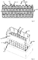
- the module housing 100 consists of an electrically insulating plastic material.
- the module housing 100 is an injection molded part.
- a foam body 102 made of an electrically insulating foam material is arranged in the module housing 100 .
- the foam body 102 has a large number of receptacles 104 for round cells.
- the receptacles 104 are arranged as densely as possible.
- a receptacle 104 is a continuous cylindrical recess from one side of the foam body 102 to an opposite side of the foam body 102 with a diameter adapted to the size of the round cell. The receptacles 104 are thus bores aligned in parallel through the foam body 102 in a hexagonal packing.
- the module housing 100 has stops 106 aligned on the receptacles 104 .
- the stops 106 each have a recess 108 . If a round cell is arranged in a receptacle 104 , the round cell is pushed into the receptacle 104 with the positive pole first, until a cell cup of the round cell rests against the stop 106 of the receptacle 104 . The round cell cannot then be pushed any further.
- the receptacle 104 fixes the round cell in the radial direction.
- the stop 106 fixes the round cell in the axial direction.
- the positive pole is arranged within the recess 108 and can be contacted from the outside with a cell connector.
- the stop 106 covers the cell cup at least at the points where the cell connector is arranged.
- the recesses 108 are circular and have a smaller diameter than the receptacles 104.
- the stops 106 are thus arranged in a circular ring around the recesses 108.
- the round cell is pushed into the receptacle 104 with the negative pole first, with a corresponding adaptation of the electrical contacting.
- the module housing 100 is divided into two, with only one of the housing halves 110 being shown here.
- the module housing 100 is designed to accommodate round cells that are aligned in opposite directions.
- the receptacles 104 are grouped in rows 112 .
- the housing half 110 has stops 106 only in every second row 112 . In the other rows 112, the stops 106 are arranged in the other housing half 110, not shown here.
- the housing half 110 has through openings 114 in the rows 112 without stops 106 .
- the through openings 114 have a larger diameter than the round cells.
- the module housing 100 has a connection contour 116 on at least one side for connection to a further module housing, in particular of the same type.
- Different connection contours are arranged here on the upper and lower sides in the illustration.
- the connection contours 116 are complementary to each other.
- the battery module 200 has a 1 corresponding module housing 100 on.
- Round cells 202 are arranged in the receptacles of the two-part module housing 100 here.
- the round cells 202 are inserted into the receptacles in opposite rows, so that in every second row 112 the cell cups 204 of the round cells 202 protrude from the receptacles as negative poles 206 and in the other rows the positive poles 208 of the round cells 202 are arranged in the recesses and the Cell cup 204 rest against the stops 106.
- the positive poles 208 of a row 112 are each electrically conductively connected to one another with a cell connector 210 .
- the stops 106 isolate the cell connector 210 from the cell cups 204.
- the round cells 202 are 21700 cells in the exemplary embodiment shown with a nominal diameter of 21 millimeters and a nominal length of 700 millimeters. In a further exemplary embodiment, it can be a question of other round cells.
- the cell connectors 210 connected to the positive poles 208 contact the exposed negative poles 206 of the other battery module 100 and connect the round cells 202 of the rows 112 aligned with one another in an electrical series circuit.
- FIG 3 shows a sectional view of a detail of a battery module 200 according to an embodiment.
- the battery module 200 essentially corresponds to the battery module 200 in FIG 2 .
- the cell cup 204 of a round cell 202 rests against the stop 106 of the module housing 100 and the positive pole 208 is arranged in the cutout 108 .
- the cell connector 210 is electrically conductively connected to the positive pole 208 .
- the cell connector 210 has an embossing 300 in the region of the positive pole 208 which, together with the overhang of the positive pole 208 in relation to the cell cup 204 or a cell jacket, bridges a material thickness of the stop 106 .
- the stop 106 is arranged as an insulator between the cell cup 204 and the cell connector 210 and prevents the round cell 202 from short-circuiting.
- the stop 106 is dimensioned such that it provides the clearance and creepage distance between the cell connector 210 and the cell cup 204 required for the cell voltage.
- the cell connector 210 has contact springs 302 on a side facing away from the battery module 200 .
- the contact springs 302 are bent out of a main plane of the cell connector 210 and are designed to contact the cell cup of another round cell on the circumference.
- the contact springs 302 have insertion bevels 304 over which the cell cup slides when two battery modules 200 are joined together.
- the contact springs 302 are elastically bent outwards by the insertion bevels 304 and thus exert a radial contact pressure on the cell cup.
- FIG. 4 10 shows a representation of a module housing 100 according to an exemplary embodiment.
- the module housing 100 like the module housing in 1 receptacles 104 arranged in hexagonal packing for round cells.
- the recesses 108 in the module housing 100 have the diameter of the receptacles 104 here.
- a plurality of stops 106 are distributed here around the circumference of each recess 108 .
- the attacks 106 are approximately semicircular and protrude into the recess 108 .
- a clear width 400 between tips of the stops 106 is smaller than the diameter of the recess 108 or smaller than the diameter of the round cells.
- the stops 106 are related to the recesses 108 as analog dials at 0:30, 1:30, 3:00, 4:30, 5:30, 3:1, 7:30, 9:00, 10:30 and Arranged at 11:30 a.m.
- the arrangement can be different, in particular symmetrical.
- the diameters of the receptacles 104 and thus the diameters of the recesses 108 are slightly larger than the diameters of the round cells.
- the foam body 102 has crushing ribs 402 as an extension of the stops 106 , which run axially along the walls of the receptacles 104 .
- a clear width 400 between the tips of the crushing ribs 402 is smaller than the diameter of the round cells.
- the crushing ribs 402 are squeezed at least partially elastically when the round cells are pushed in and thus securely hold the round cells in the radial direction. The squeezing creates a contact pressure of the squeezing ribs 402 on the cell cup.
- the crushing ribs 402 provide a volume that can be crushed when pushed in.
- the volume of the crushing ribs 402 is smaller than a volume to be displaced in a cylindrical recess with a corresponding clear width 400, in particular significantly smaller. Due to the crushing ribs 402, the fixation of the round cells is less susceptible to tolerances than with a cylindrical recess alone. Even taking into account all specified tolerances, the crushable volume between a maximum crush case and a minimum crush case only changes in the ratio of 1.67:1. In another embodiment, the ratio may be different.
- the module housing 100 like the module housing in 1 on two opposite sides complementary connection contours 116 for connection to a similar module housing.
- figure 5 10 shows a representation of a battery module 200 according to an embodiment.
- the battery module 200 has the module housing 100 4 on.
- the round cells 202 are in contrast to the representation in 2 all from the same side and facing the same way pushed into the mounts until they rest against the stops.
- the positive poles 208 and cell connectors 210 are all arranged on the same side of the battery module 200 .
- the cell connectors 210 have as in 3 Stampings 300 and contact springs 302 on.
- the cell connectors 210 have an embossing 300 and eight contact springs 302 per round cell 202 .
- the contact springs 302 are positioned over the stops at 0:30, 1:30, 4:30, 5:30, 3:1, 7:30, 10:30 and 11:30. Connecting webs 500 between adjacent positive poles are arranged above the stops at 3:00 and 9:00 o'clock. In particular, the contact springs 302 are arranged as precisely as possible over the stops.
- FIG. 6 shows a spatial representation of a foaming tool 600 with a module housing 100 according to an embodiment.
- the module housing 100 essentially corresponds to the module housing 100 in 4 .
- no foam body is arranged in the module housing.
- the foamed body is foamed using the foaming tool 600 .
- the module housing 100 is injection molded from an electrically insulating plastic material in an injection molding tool.
- the module housing 100 is then inserted into the foaming tool 600 with the recesses 108 and the stops 106 in front.
- a foaming core 602 of the foaming tool 600 is inserted into the module housing 100 through each recess 108 .
- Sidewalls 604 of module housing 100 are supported by sidewalls of foaming tool 600 .
- the foam cores 602 are placeholders for receiving the foam body.
- the foam cores 602 are essentially cylindrical and essentially as long as the module housing 100 is high. In order to be able to be inserted, the foam cores 602 have cross-sectional areas corresponding to the recesses 108 . The cross-sectional areas also depict the stops 106 . As a result, the foam cores 602 seal the module housing 100 at the recesses 108 and stops 106 and a sealed mold cavity which is open at the top and is formed within the side walls 604 of the module housing 100 .
- the stops 106 are shown on the foam cores 602 as grooves 606 running axially. The grooves 606 are formed in the foam material during foaming and thus form the crush ribs running axially along the receptacles.
- the foam material is metered into the mold cavity in liquid form.
- the mold cavity is then closed by a lid.
- the cover is not pressure-tight and can have pressure equalization openings.
- the foaming takes place without pressure.
- the side walls 604 are not deformed in the process.
- the foam material reacts in the mold cavity to form a solid foam, which molds the mold cavity including the foam cores 602 completely.
- the foam material can also connect firmly to the side walls.
- the foam cores 602 are designed in such a way that the foam material does not adhere to the foam cores 602 firmly.
- the module housing with the foamed-in foam body is removed from the foaming tool 600 .
- the foam cores 602 are pulled out of the foam body again through the recesses 108 .
- the shrink tubing can fix an insulating disk, which may be necessary in the case of cell contacting using cell connectors. If, when assembling the cell modules, the cells are not exactly aligned in the axial direction or the cell connectors have too small a diameter, the cell bottom of the second cell can collide with the cell connector of the first cell. This can lead to the cell connector being bent in such a way that it touches the jacket of the first cell and thus the negative pole of the same cell, which leads to a short circuit and thus damage to the cell. It is therefore necessary to fix the insulating washer to the cell in a different way, so that it cannot be detached from the cells under any circumstances before the modules are assembled.
- the insulating pane can be glued, for example.
- modules do not have a positioning and fixing device, this can lead to the cells "wandering"/slipping within the modules during operation be able. This, in turn, can cause the cells to lose contact, leading to either partial or total battery failure. In the worst-case scenario, an arc could occur, which could lead to major damage or even a fire in the battery.
- the cells are positioned and fixed in the module housing in the axial direction.
- the approach presented here prevents an electrical short circuit if the cell cup of another cell collides with the cell connector of the first cell during assembly.
- the cells are inserted with the positive pole first into the openings provided in the module.
- the diameter of the openings can be equal to or slightly larger than the diameter of the cells.
- the module is designed in such a way that the cell can only be plugged in up to the desired end position. This is achieved by the last opening being smaller than the cell.
- the positive pole of the cell looks out of this opening; the jacket (and thus the negative pole) is covered by the smaller opening in the housing.
- the opening is so large that the cell connector can be installed (e.g. by welding). The opening is small enough to cover the cell's cup shoulder.
- a foam body with the appropriate openings to accommodate the cells is used to position and fix the cells in the axial direction.
- the opening in the module housing has a special shape to simplify manufacture. As a result, the foam cores can be demoulded in the direction of the closed tool housing side. This allows foaming into the open shape of the tool.
- the foam core which is more or less the same diameter as the cell, can be pulled through a smaller hole that represents the insulator or stop.
- the solution presented here is not to use a closed ring as a stop and insulator, but only partial constrictions over the circumference.
- the foam core thus has corresponding grooves, which then appear as "crush ribs" in the foam itself and thus also serve to fix the cell.
- the stops are positioned exactly at the points where the material of the cell crown is also located, because in the areas between the contact springs of the cell crown and the connecting webs to the next cell crown, no short circuit to the cell jacket can occur. Thus, when viewed from above, the stops are more or less covered by the cell crown.
- FIG 4 shows a simplified representation of a module housing.
- the insulators and stops are the 10 small bulges in the 36 circles. They have defined positions resulting from the geometry of the cell crowns.
- Bulges for the contact springs of the cell crowns are arranged at the positions 0:30, 1:30, 4:30, 5:30, 3:1, 7:30, 10:30 and 11:30. Furthermore, bulges for isolating the connecting webs of the cell crowns are arranged at the positions 3 o'clock and 9 o'clock.
- a schematic structure of a foaming tool is shown. It has an essentially rectangular cavity with 36 foam cores.
- a module housing can thus be inserted into this cavity with the opening pointing upwards.
- the appropriate quantity of the polyol-isocyanate mixture conditioned by the mixing plant is then dosed into the open mold and the mold is then closed with a corresponding cover.
- the mass now starts to react and expands, filling the entire cavity of the module housing.
- the cover can be opened again and the completely foamed module housing can be removed from the cavity.
- the result is a case with a hard outer shell and soft holes inside, which then accept the cells.
- the resulting ribs serve to fix the cells radially in that the foam adapts exactly to the cell diameter when the cells are inserted into the hole.
- the ribs result in a small "displacement volume" with small joining forces. If, on the other hand, a cell were pressed into a circular hole, which is on the is matched to the smallest possible diameter of a cell, then the forces would be significantly higher for a cell with a diameter at the upper tolerance limit, since the displacement volume would be larger.
- the fixation with ribs is less susceptible to tolerances than a fixation without ribs.
Landscapes
- Chemical & Material Sciences (AREA)
- Chemical Kinetics & Catalysis (AREA)
- Electrochemistry (AREA)
- General Chemical & Material Sciences (AREA)
- Engineering & Computer Science (AREA)
- Aviation & Aerospace Engineering (AREA)
- Manufacturing & Machinery (AREA)
- Battery Mounting, Suspending (AREA)
- Sealing Battery Cases Or Jackets (AREA)
Applications Claiming Priority (1)
| Application Number | Priority Date | Filing Date | Title |
|---|---|---|---|
| DE102021102975.9A DE102021102975B4 (de) | 2021-02-09 | 2021-02-09 | Modulgehäuse, verfahren zum herstellen eines modulgehäuses und batteriemodul |
Publications (2)
| Publication Number | Publication Date |
|---|---|
| EP4040585A1 true EP4040585A1 (fr) | 2022-08-10 |
| EP4040585B1 EP4040585B1 (fr) | 2025-10-08 |
Family
ID=79830998
Family Applications (1)
| Application Number | Title | Priority Date | Filing Date |
|---|---|---|---|
| EP22152401.0A Active EP4040585B1 (fr) | 2021-02-09 | 2022-01-20 | Boîtier de module, procédé de fabrication d'un boîtier de module et module de batterie |
Country Status (4)
| Country | Link |
|---|---|
| US (1) | US20220263172A1 (fr) |
| EP (1) | EP4040585B1 (fr) |
| CN (1) | CN114914607B (fr) |
| DE (1) | DE102021102975B4 (fr) |
Cited By (1)
| Publication number | Priority date | Publication date | Assignee | Title |
|---|---|---|---|---|
| DE102023002761A1 (de) | 2023-07-05 | 2025-01-09 | Mercedes-Benz Group AG | Vorrichtung und Verfahren zum elektrisch leitfähigen Überbrücken einer Batteriezelle in einem Batteriezellverbund |
Families Citing this family (2)
| Publication number | Priority date | Publication date | Assignee | Title |
|---|---|---|---|---|
| EP4420182A4 (fr) * | 2021-10-18 | 2025-11-05 | Flyer Next Llc | Fond de panier de batterie de véhicule configurable et modules et leurs procédés de fonctionnement |
| EP4496073A1 (fr) * | 2023-07-18 | 2025-01-22 | VARTA Microbattery GmbH | Ensemble de serrage comprenant un support d'élément et une pluralité d'éléments accumulateurs d'énergie électrochimiques |
Citations (4)
| Publication number | Priority date | Publication date | Assignee | Title |
|---|---|---|---|---|
| DE102014002165B3 (de) * | 2014-02-19 | 2015-01-22 | Lisa Dräxlmaier GmbH | Verfahren zur Fixierung von Rundzellen mittels komprimierter Zellenfixierung und Zellenblock |
| CN106252549A (zh) * | 2016-08-01 | 2016-12-21 | 杜桂菊 | 一种轻质、安全电芯支架及动力电池包 |
| DE102018009445A1 (de) * | 2017-11-29 | 2019-06-06 | Whiterock Ag | Modulares Batteriesystem aus Batteriepacks bestehend aus zusammensteckbaren Modulen mit selbsttragendem Kunststoffgehäuse |
| WO2020094218A1 (fr) * | 2018-11-06 | 2020-05-14 | Lisa Dräxlmaier GmbH | Connecteur de cellules servant à relier de manière électroconductrice des cellules rondes d'une batterie pour un véhicule automobile, et procédé de fabrication d'une batterie pour un véhicule automobile |
Family Cites Families (9)
| Publication number | Priority date | Publication date | Assignee | Title |
|---|---|---|---|---|
| CN201514969U (zh) * | 2009-11-06 | 2010-06-23 | 李然 | 电池组中电池的串联和并联结构 |
| DE102010041589A1 (de) | 2010-09-29 | 2012-03-29 | Robert Bosch Gmbh | Gehäuseelement zur Aufnahme einer Leistungselektronik einer Elektromaschine, Gehäuse für eine Elektromaschine, Werkzeug zur Herstellung eines Gehäuseelementes sowie Verfahren zur Herstellung eines Gehäuses für eine Elektromaschine |
| US10347894B2 (en) * | 2017-01-20 | 2019-07-09 | Tesla, Inc. | Energy storage system |
| WO2016067517A1 (fr) * | 2014-10-29 | 2016-05-06 | 三洋電機株式会社 | Bloc-batterie et support de dissipation de chaleur |
| CN109314200B (zh) * | 2016-06-29 | 2022-04-08 | 松下知识产权经营株式会社 | 电池模块 |
| DE102016222264A1 (de) * | 2016-11-14 | 2018-05-30 | Robert Bosch Gmbh | Batteriemodul, Verfahren zu dessen Herstellung und Batterie |
| KR102248229B1 (ko) * | 2018-01-15 | 2021-05-03 | 주식회사 엘지화학 | 가스 배출 구조가 형성된 배터리 모듈 |
| DE102018208342A1 (de) * | 2018-05-28 | 2019-11-28 | Robert Bosch Gmbh | Gehäuse für ein Batteriemodul und Batteriemodul |
| DE202018106375U1 (de) * | 2018-11-09 | 2018-11-15 | Lisa Dräxlmaier GmbH | Zellverbinder zum elektrisch leitenden Verbinden von Rundzellen einer Batterie für ein Kraftfahrzeug sowie entsprechende Batterie |
-
2021
- 2021-02-09 DE DE102021102975.9A patent/DE102021102975B4/de active Active
-
2022
- 2022-01-20 EP EP22152401.0A patent/EP4040585B1/fr active Active
- 2022-01-27 CN CN202210099665.7A patent/CN114914607B/zh active Active
- 2022-02-09 US US17/667,576 patent/US20220263172A1/en active Pending
Patent Citations (4)
| Publication number | Priority date | Publication date | Assignee | Title |
|---|---|---|---|---|
| DE102014002165B3 (de) * | 2014-02-19 | 2015-01-22 | Lisa Dräxlmaier GmbH | Verfahren zur Fixierung von Rundzellen mittels komprimierter Zellenfixierung und Zellenblock |
| CN106252549A (zh) * | 2016-08-01 | 2016-12-21 | 杜桂菊 | 一种轻质、安全电芯支架及动力电池包 |
| DE102018009445A1 (de) * | 2017-11-29 | 2019-06-06 | Whiterock Ag | Modulares Batteriesystem aus Batteriepacks bestehend aus zusammensteckbaren Modulen mit selbsttragendem Kunststoffgehäuse |
| WO2020094218A1 (fr) * | 2018-11-06 | 2020-05-14 | Lisa Dräxlmaier GmbH | Connecteur de cellules servant à relier de manière électroconductrice des cellules rondes d'une batterie pour un véhicule automobile, et procédé de fabrication d'une batterie pour un véhicule automobile |
Cited By (1)
| Publication number | Priority date | Publication date | Assignee | Title |
|---|---|---|---|---|
| DE102023002761A1 (de) | 2023-07-05 | 2025-01-09 | Mercedes-Benz Group AG | Vorrichtung und Verfahren zum elektrisch leitfähigen Überbrücken einer Batteriezelle in einem Batteriezellverbund |
Also Published As
| Publication number | Publication date |
|---|---|
| DE102021102975B4 (de) | 2025-02-27 |
| DE102021102975A1 (de) | 2022-08-11 |
| CN114914607B (zh) | 2024-08-16 |
| CN114914607A (zh) | 2022-08-16 |
| US20220263172A1 (en) | 2022-08-18 |
| EP4040585B1 (fr) | 2025-10-08 |
Similar Documents
| Publication | Publication Date | Title |
|---|---|---|
| EP4040585B1 (fr) | Boîtier de module, procédé de fabrication d'un boîtier de module et module de batterie | |
| EP2715862B1 (fr) | Batterie pour véhicule, et procédé de production d'une batterie | |
| DE69526682T2 (de) | Bürstenhalteranordnung | |
| DE102014106438B4 (de) | Einhausungssystem zum Zurückhalten eines Batteriesystems | |
| DE102012101771B4 (de) | Klemmenanschlusseinrichtung für ein energiespeichermodul | |
| DE102013016101B4 (de) | Verfahren zum Herstellen eines Batteriemoduls und Batteriemodul | |
| DE112013005946T5 (de) | Elektrischer Verdichter und Verfahren zu dessen Zusammenbau | |
| DE102007010742A1 (de) | Zellverbund einer Batterie | |
| DE102013210585A1 (de) | Gehäusevorrichtung für zumindest eine Energiespeicherzelle und Verfahren zum Herstellen einer Gehäusevorrichtung für zumindest eine Energiespeicherzelle | |
| DE102008034699A1 (de) | Batterie mit mehreren Batteriezellen | |
| DE2404998A1 (de) | Elektrischer verbindungsstecker | |
| EP3804003B1 (fr) | Boîtier pour module de batterie et module de batterie | |
| DE102022001673A1 (de) | Deckelbaugruppe für eine Batteriezelle und Batteriezelle | |
| DE102021204119A1 (de) | Elektrisches Antriebssystem für ein Fahrzeug und Abschirmungsvorrichtung zur elektromagnetischen Abschirmung von elektrischen oder elektronischen Bauteilen | |
| DE112018005157T5 (de) | Motor und elektrisches servolenksystem | |
| WO2020030651A1 (fr) | Boîtier de batterie, système de batterie et procédé de montage pour un système de batterie | |
| DE212022000381U1 (de) | Batterie, Batteriemodul und Batteriepaket | |
| WO2019092072A1 (fr) | Boîtier de module pour un module de batterie empilable, module de batterie et empilement de batteries | |
| DE4006309C2 (fr) | ||
| DE102021211929A1 (de) | Batteriezellgehäuse mit Zellwandung aus einem Faserverbundwerkstoff, Batteriezelle und Batterie | |
| EP0907928A1 (fr) | Grille de connexion pour le montage d'un circuit integre dans un boitier moule par injection | |
| EP3994762A1 (fr) | Connecteur d'éléments pour éléments et modules d'éléments et modules de batterie dotés d'éléments | |
| EP4152538A1 (fr) | Distributeur de puissance haute tension | |
| DE102023132171B3 (de) | Batteriemodul einer Traktionsbatterie, Verfahren zum Herstellen desselben und Traktionsbatterie | |
| DE202022105548U1 (de) | Sekundärbatterie vom Knopftyp |
Legal Events
| Date | Code | Title | Description |
|---|---|---|---|
| PUAI | Public reference made under article 153(3) epc to a published international application that has entered the european phase |
Free format text: ORIGINAL CODE: 0009012 |
|
| STAA | Information on the status of an ep patent application or granted ep patent |
Free format text: STATUS: THE APPLICATION HAS BEEN PUBLISHED |
|
| AK | Designated contracting states |
Kind code of ref document: A1 Designated state(s): AL AT BE BG CH CY CZ DE DK EE ES FI FR GB GR HR HU IE IS IT LI LT LU LV MC MK MT NL NO PL PT RO RS SE SI SK SM TR |
|
| STAA | Information on the status of an ep patent application or granted ep patent |
Free format text: STATUS: REQUEST FOR EXAMINATION WAS MADE |
|
| 17P | Request for examination filed |
Effective date: 20230209 |
|
| RBV | Designated contracting states (corrected) |
Designated state(s): AL AT BE BG CH CY CZ DE DK EE ES FI FR GB GR HR HU IE IS IT LI LT LU LV MC MK MT NL NO PL PT RO RS SE SI SK SM TR |
|
| GRAP | Despatch of communication of intention to grant a patent |
Free format text: ORIGINAL CODE: EPIDOSNIGR1 |
|
| STAA | Information on the status of an ep patent application or granted ep patent |
Free format text: STATUS: GRANT OF PATENT IS INTENDED |
|
| RIC1 | Information provided on ipc code assigned before grant |
Ipc: H01M 50/502 20210101ALN20250404BHEP Ipc: H01M 50/249 20210101ALI20250404BHEP Ipc: H01M 50/244 20210101ALI20250404BHEP Ipc: H01M 50/233 20210101ALI20250404BHEP Ipc: H01M 50/227 20210101ALI20250404BHEP Ipc: H01M 50/213 20210101ALI20250404BHEP Ipc: H01M 10/04 20060101ALI20250404BHEP Ipc: H01M 50/293 20210101ALI20250404BHEP Ipc: H01M 50/291 20210101AFI20250404BHEP |
|
| INTG | Intention to grant announced |
Effective date: 20250428 |
|
| GRAS | Grant fee paid |
Free format text: ORIGINAL CODE: EPIDOSNIGR3 |
|
| GRAA | (expected) grant |
Free format text: ORIGINAL CODE: 0009210 |
|
| STAA | Information on the status of an ep patent application or granted ep patent |
Free format text: STATUS: THE PATENT HAS BEEN GRANTED |
|
| AK | Designated contracting states |
Kind code of ref document: B1 Designated state(s): AL AT BE BG CH CY CZ DE DK EE ES FI FR GB GR HR HU IE IS IT LI LT LU LV MC MK MT NL NO PL PT RO RS SE SI SK SM TR |
|
| REG | Reference to a national code |
Ref country code: GB Ref legal event code: FG4D Free format text: NOT ENGLISH Ref country code: CH Ref legal event code: F10 Free format text: ST27 STATUS EVENT CODE: U-0-0-F10-F00 (AS PROVIDED BY THE NATIONAL OFFICE) Effective date: 20251008 |
|
| REG | Reference to a national code |
Ref country code: DE Ref legal event code: R096 Ref document number: 502022005672 Country of ref document: DE |
|
| REG | Reference to a national code |
Ref country code: IE Ref legal event code: FG4D Free format text: LANGUAGE OF EP DOCUMENT: GERMAN |
|
| REG | Reference to a national code |
Ref country code: NL Ref legal event code: MP Effective date: 20251008 |
|
| PG25 | Lapsed in a contracting state [announced via postgrant information from national office to epo] |
Ref country code: NL Free format text: LAPSE BECAUSE OF FAILURE TO SUBMIT A TRANSLATION OF THE DESCRIPTION OR TO PAY THE FEE WITHIN THE PRESCRIBED TIME-LIMIT Effective date: 20251008 |
|
| PG25 | Lapsed in a contracting state [announced via postgrant information from national office to epo] |
Ref country code: ES Free format text: LAPSE BECAUSE OF FAILURE TO SUBMIT A TRANSLATION OF THE DESCRIPTION OR TO PAY THE FEE WITHIN THE PRESCRIBED TIME-LIMIT Effective date: 20251008 |
|
| REG | Reference to a national code |
Ref country code: LT Ref legal event code: MG9D |
|
| PG25 | Lapsed in a contracting state [announced via postgrant information from national office to epo] |
Ref country code: NO Free format text: LAPSE BECAUSE OF FAILURE TO SUBMIT A TRANSLATION OF THE DESCRIPTION OR TO PAY THE FEE WITHIN THE PRESCRIBED TIME-LIMIT Effective date: 20260108 |
|
| PG25 | Lapsed in a contracting state [announced via postgrant information from national office to epo] |
Ref country code: HR Free format text: LAPSE BECAUSE OF FAILURE TO SUBMIT A TRANSLATION OF THE DESCRIPTION OR TO PAY THE FEE WITHIN THE PRESCRIBED TIME-LIMIT Effective date: 20251008 Ref country code: FI Free format text: LAPSE BECAUSE OF FAILURE TO SUBMIT A TRANSLATION OF THE DESCRIPTION OR TO PAY THE FEE WITHIN THE PRESCRIBED TIME-LIMIT Effective date: 20251008 |
|
| PGFP | Annual fee paid to national office [announced via postgrant information from national office to epo] |
Ref country code: AT Payment date: 20260301 Year of fee payment: 5 |
|
| PG25 | Lapsed in a contracting state [announced via postgrant information from national office to epo] |
Ref country code: RS Free format text: LAPSE BECAUSE OF FAILURE TO SUBMIT A TRANSLATION OF THE DESCRIPTION OR TO PAY THE FEE WITHIN THE PRESCRIBED TIME-LIMIT Effective date: 20260108 |
|
| PG25 | Lapsed in a contracting state [announced via postgrant information from national office to epo] |
Ref country code: IS Free format text: LAPSE BECAUSE OF FAILURE TO SUBMIT A TRANSLATION OF THE DESCRIPTION OR TO PAY THE FEE WITHIN THE PRESCRIBED TIME-LIMIT Effective date: 20260208 |
|
| PG25 | Lapsed in a contracting state [announced via postgrant information from national office to epo] |
Ref country code: PT Free format text: LAPSE BECAUSE OF FAILURE TO SUBMIT A TRANSLATION OF THE DESCRIPTION OR TO PAY THE FEE WITHIN THE PRESCRIBED TIME-LIMIT Effective date: 20260209 |
|
| PG25 | Lapsed in a contracting state [announced via postgrant information from national office to epo] |
Ref country code: PL Free format text: LAPSE BECAUSE OF FAILURE TO SUBMIT A TRANSLATION OF THE DESCRIPTION OR TO PAY THE FEE WITHIN THE PRESCRIBED TIME-LIMIT Effective date: 20251008 |
|
| PG25 | Lapsed in a contracting state [announced via postgrant information from national office to epo] |
Ref country code: LV Free format text: LAPSE BECAUSE OF FAILURE TO SUBMIT A TRANSLATION OF THE DESCRIPTION OR TO PAY THE FEE WITHIN THE PRESCRIBED TIME-LIMIT Effective date: 20251008 |
|
| PG25 | Lapsed in a contracting state [announced via postgrant information from national office to epo] |
Ref country code: BG Free format text: LAPSE BECAUSE OF FAILURE TO SUBMIT A TRANSLATION OF THE DESCRIPTION OR TO PAY THE FEE WITHIN THE PRESCRIBED TIME-LIMIT Effective date: 20251008 |
|
| PG25 | Lapsed in a contracting state [announced via postgrant information from national office to epo] |
Ref country code: LT Free format text: LAPSE BECAUSE OF FAILURE TO SUBMIT A TRANSLATION OF THE DESCRIPTION OR TO PAY THE FEE WITHIN THE PRESCRIBED TIME-LIMIT Effective date: 20251008 |
|
| PG25 | Lapsed in a contracting state [announced via postgrant information from national office to epo] |
Ref country code: SM Free format text: LAPSE BECAUSE OF FAILURE TO SUBMIT A TRANSLATION OF THE DESCRIPTION OR TO PAY THE FEE WITHIN THE PRESCRIBED TIME-LIMIT Effective date: 20251008 |
|
| PG25 | Lapsed in a contracting state [announced via postgrant information from national office to epo] |
Ref country code: DK Free format text: LAPSE BECAUSE OF FAILURE TO SUBMIT A TRANSLATION OF THE DESCRIPTION OR TO PAY THE FEE WITHIN THE PRESCRIBED TIME-LIMIT Effective date: 20251008 |
|
| PG25 | Lapsed in a contracting state [announced via postgrant information from national office to epo] |
Ref country code: IT Free format text: LAPSE BECAUSE OF FAILURE TO SUBMIT A TRANSLATION OF THE DESCRIPTION OR TO PAY THE FEE WITHIN THE PRESCRIBED TIME-LIMIT Effective date: 20251008 |
|
| PGFP | Annual fee paid to national office [announced via postgrant information from national office to epo] |
Ref country code: DE Payment date: 20260630 Year of fee payment: 5 |
|
| PG25 | Lapsed in a contracting state [announced via postgrant information from national office to epo] |
Ref country code: EE Free format text: LAPSE BECAUSE OF FAILURE TO SUBMIT A TRANSLATION OF THE DESCRIPTION OR TO PAY THE FEE WITHIN THE PRESCRIBED TIME-LIMIT Effective date: 20251008 |
|
| PG25 | Lapsed in a contracting state [announced via postgrant information from national office to epo] |
Ref country code: CZ Free format text: LAPSE BECAUSE OF FAILURE TO SUBMIT A TRANSLATION OF THE DESCRIPTION OR TO PAY THE FEE WITHIN THE PRESCRIBED TIME-LIMIT Effective date: 20251008 |
|
| PGFP | Annual fee paid to national office [announced via postgrant information from national office to epo] |
Ref country code: FR Payment date: 20260408 Year of fee payment: 5 |
|
| PG25 | Lapsed in a contracting state [announced via postgrant information from national office to epo] |
Ref country code: SK Free format text: LAPSE BECAUSE OF FAILURE TO SUBMIT A TRANSLATION OF THE DESCRIPTION OR TO PAY THE FEE WITHIN THE PRESCRIBED TIME-LIMIT Effective date: 20251008 |
|
| PG25 | Lapsed in a contracting state [announced via postgrant information from national office to epo] |
Ref country code: SE Free format text: LAPSE BECAUSE OF FAILURE TO SUBMIT A TRANSLATION OF THE DESCRIPTION OR TO PAY THE FEE WITHIN THE PRESCRIBED TIME-LIMIT Effective date: 20251008 |
|
| PLBE | No opposition filed within time limit |
Free format text: ORIGINAL CODE: 0009261 |
|
| STAA | Information on the status of an ep patent application or granted ep patent |
Free format text: STATUS: NO OPPOSITION FILED WITHIN TIME LIMIT |