EP4040586A1 - Battery pack and device including same - Google Patents
Battery pack and device including same Download PDFInfo
- Publication number
- EP4040586A1 EP4040586A1 EP21796832.0A EP21796832A EP4040586A1 EP 4040586 A1 EP4040586 A1 EP 4040586A1 EP 21796832 A EP21796832 A EP 21796832A EP 4040586 A1 EP4040586 A1 EP 4040586A1
- Authority
- EP
- European Patent Office
- Prior art keywords
- venting
- battery
- battery pack
- passage
- gate
- Prior art date
- Legal status (The legal status is an assumption and is not a legal conclusion. Google has not performed a legal analysis and makes no representation as to the accuracy of the status listed.)
- Pending
Links
Images


Classifications
-
- H—ELECTRICITY
- H01—ELECTRIC ELEMENTS
- H01M—PROCESSES OR MEANS, e.g. BATTERIES, FOR THE DIRECT CONVERSION OF CHEMICAL ENERGY INTO ELECTRICAL ENERGY
- H01M50/00—Constructional details or processes of manufacture of the non-active parts of electrochemical cells other than fuel cells, e.g. hybrid cells
- H01M50/30—Arrangements for facilitating escape of gases
- H01M50/342—Non-re-sealable arrangements
- H01M50/3425—Non-re-sealable arrangements in the form of rupturable membranes or weakened parts, e.g. pierced with the aid of a sharp member
-
- H—ELECTRICITY
- H01—ELECTRIC ELEMENTS
- H01M—PROCESSES OR MEANS, e.g. BATTERIES, FOR THE DIRECT CONVERSION OF CHEMICAL ENERGY INTO ELECTRICAL ENERGY
- H01M50/00—Constructional details or processes of manufacture of the non-active parts of electrochemical cells other than fuel cells, e.g. hybrid cells
- H01M50/20—Mountings; Secondary casings or frames; Racks, modules or packs; Suspension devices; Shock absorbers; Transport or carrying devices; Holders
- H01M50/233—Mountings; Secondary casings or frames; Racks, modules or packs; Suspension devices; Shock absorbers; Transport or carrying devices; Holders characterised by physical properties of casings or racks, e.g. dimensions
- H01M50/24—Mountings; Secondary casings or frames; Racks, modules or packs; Suspension devices; Shock absorbers; Transport or carrying devices; Holders characterised by physical properties of casings or racks, e.g. dimensions adapted for protecting batteries from their environment, e.g. from corrosion
-
- H—ELECTRICITY
- H01—ELECTRIC ELEMENTS
- H01M—PROCESSES OR MEANS, e.g. BATTERIES, FOR THE DIRECT CONVERSION OF CHEMICAL ENERGY INTO ELECTRICAL ENERGY
- H01M50/00—Constructional details or processes of manufacture of the non-active parts of electrochemical cells other than fuel cells, e.g. hybrid cells
- H01M50/30—Arrangements for facilitating escape of gases
- H01M50/342—Non-re-sealable arrangements
-
- H—ELECTRICITY
- H01—ELECTRIC ELEMENTS
- H01M—PROCESSES OR MEANS, e.g. BATTERIES, FOR THE DIRECT CONVERSION OF CHEMICAL ENERGY INTO ELECTRICAL ENERGY
- H01M50/00—Constructional details or processes of manufacture of the non-active parts of electrochemical cells other than fuel cells, e.g. hybrid cells
- H01M50/30—Arrangements for facilitating escape of gases
- H01M50/35—Gas exhaust passages comprising elongated, tortuous or labyrinth-shaped exhaust passages
- H01M50/367—Internal gas exhaust passages forming part of the battery cover or case; Double cover vent systems
-
- H—ELECTRICITY
- H01—ELECTRIC ELEMENTS
- H01M—PROCESSES OR MEANS, e.g. BATTERIES, FOR THE DIRECT CONVERSION OF CHEMICAL ENERGY INTO ELECTRICAL ENERGY
- H01M50/00—Constructional details or processes of manufacture of the non-active parts of electrochemical cells other than fuel cells, e.g. hybrid cells
- H01M50/30—Arrangements for facilitating escape of gases
- H01M50/383—Flame arresting or ignition-preventing means
-
- H—ELECTRICITY
- H01—ELECTRIC ELEMENTS
- H01M—PROCESSES OR MEANS, e.g. BATTERIES, FOR THE DIRECT CONVERSION OF CHEMICAL ENERGY INTO ELECTRICAL ENERGY
- H01M2200/00—Safety devices for primary or secondary batteries
- H01M2200/20—Pressure-sensitive devices
-
- H—ELECTRICITY
- H01—ELECTRIC ELEMENTS
- H01M—PROCESSES OR MEANS, e.g. BATTERIES, FOR THE DIRECT CONVERSION OF CHEMICAL ENERGY INTO ELECTRICAL ENERGY
- H01M2220/00—Batteries for particular applications
- H01M2220/20—Batteries in motive systems, e.g. vehicle, ship, plane
-
- Y—GENERAL TAGGING OF NEW TECHNOLOGICAL DEVELOPMENTS; GENERAL TAGGING OF CROSS-SECTIONAL TECHNOLOGIES SPANNING OVER SEVERAL SECTIONS OF THE IPC; TECHNICAL SUBJECTS COVERED BY FORMER USPC CROSS-REFERENCE ART COLLECTIONS [XRACs] AND DIGESTS
- Y02—TECHNOLOGIES OR APPLICATIONS FOR MITIGATION OR ADAPTATION AGAINST CLIMATE CHANGE
- Y02E—REDUCTION OF GREENHOUSE GAS [GHG] EMISSIONS, RELATED TO ENERGY GENERATION, TRANSMISSION OR DISTRIBUTION
- Y02E60/00—Enabling technologies; Technologies with a potential or indirect contribution to GHG emissions mitigation
- Y02E60/10—Energy storage using batteries
Definitions
- the present invention relates to a battery pack and a device including the same, and in particular, it relates to a safety-improved battery pack and a device including the same.
- Rechargeable batteries having high application characteristics and electrical characteristics such as high energy density according to their products are widely applied to battery vehicles, hybrid vehicles, and electric power storage devices driven by electric driving sources, as well as portable devices. These rechargeable batteries are attracting attention as new energy sources for improving environmental friendliness and energy efficiency in that they do not generate any by-products of energy use, as well as their primary merit that they can drastically reduce the use of fossil fuels.
- the commercially available secondary batteries include a nickel cadmium battery, a nickel hydrogen battery, a nickel zinc battery, and a lithium secondary battery, and the lithium secondary battery among them scarcely generates a memory effect compared to the nickel-based secondary battery so it is freely charged and discharged, a self-discharge rate is very low, and an energy density is high as merits.
- the lithium secondary battery generally uses a lithium-based oxide and a carbon material as a positive active material and a negative active material, respectively.
- the lithium secondary battery includes an electrode assembly in which a positive electrode plate and a negative electrode plate on which the positive active material and the negative active material are respectively applied are disposed with a separator therebetween, and an exterior material, that is, a battery case, for sealing and receiving the electrode assembly together with an electrolyte solution.
- the lithium secondary battery may be classified into a cylindrical or square-type secondary battery of which the electrode assembly is installed in a metal can, and a pouch-type secondary battery of which the electrode assembly is installed in a pouch of an aluminum laminate sheet, depending on a shape of the exterior material.
- the battery pack has a structure in which a plurality of battery modules are combined, so when some of the battery modules receive an overvoltage or an overcurrent or they are overheated, safety and operation efficiency of the battery pack may be problematic.
- the capacity of the battery pack is in the increasing trend to improve mileage and energy inside the pack is accordingly increasing, there is a need to design a structure satisfying reinforcing safety standards and obtaining safety of vehicles and drivers.
- the need for acquiring a structure for preventing an internal thermal runaway in advance, and minimizing corresponding damages when the thermal runaway is generated, is particularly on the rise.
- the present invention has been made in an effort to provide a safety-improved battery pack and a device including the same.
- An embodiment of the present invention provides a battery pack including: a plurality of battery modules; a venting inducing frame disposed along an edge of the battery modules and forming a venting passage; and a venting gate for connecting an inside of the battery modules and the venting inducing frame, wherein a quenching member is formed on a passage of the venting gate.
- the quenching member may be made of a quenching mesh.
- the venting inducing frame may include a pair of vertical beams formed in parallel to a first direction and a pair of horizontal beams formed in parallel to a second direction traversing the first direction, and the vertical beams and the horizontal beams respectively having a pipe shape may include a cover formed in length directions of the vertical beams and the horizontal beams, and a passage surrounded by the cover and formed to allow gas to pass through.
- the battery pack may further include at least one rupture portion connected to the passage on an outside of one of the horizontal beams and the vertical beams.
- a passage of the venting gate and a passage of the rupture portion may be formed to cross each other.
- the cover of the horizontal beams may include at least one first connection hole facing the battery module, and the venting gate may be formed so that a pipe shape of the venting gate may communicate with a pipe shape of the horizontal beams facing the first connection hole.
- a second connection hole communicating with a passage of another of the vertical beams and the horizontal beams may be installed on a cover of one of the vertical beams and the horizontal beams on a portion where the vertical beams traverse the horizontal beams.
- the battery pack may further include a pack housing for receiving the battery modules and the venting inducing frame, wherein the pack housing may include an upper cover and a lower housing, and a pack gasket may be formed between the upper cover and the lower housing.
- the battery modules may include an end plate for covering a battery cell stacked body exposed on a front side and a rear side of a module frame, an opening may be formed in part of the end plate, and the venting gate may be connected to an opening of the end plate.
- a gate gasket may be formed between the venting gate and the end plate.
- Another embodiment of the present invention provides a device including the above-described battery pack.
- the venting inducing structure is provided in the battery pack, so when an abnormal phenomenon is generated in the battery cell, the safety of the battery pack may be secured by inducing venting gas in a predetermined direction.
- the phrase “in a plan view” means viewing a target portion from the top
- the phrase “in a cross-sectional view” means viewing a cross-section formed by vertically cutting a target portion from the side.
- FIG. 1 shows a battery module according to an embodiment of the present invention.
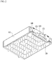
- FIG. 2 shows a perspective view of a battery module of FIG. 1 seen from bottom to top in a z-axis direction.
- the battery module 100 included in the battery pack of FIG. 1 may include a battery cell stacked body 102 in which a plurality of battery cells 101 are stacked, a module frame 108 for receiving the battery cell stacked body 102, and an end plate 120.
- the battery cells 101 are stacked to be mutually electrically connected to each other to configure the battery cell stacked body 102.
- a plurality of battery cells 101 may be stacked in a direction that is parallel to the y-axis.
- the battery cell stacked body 102 may be a large-area module including a greater number of the battery cells 101 than the prior art. For example, 48 battery cells 101 may be included per battery module 100.
- a horizontal direction length of the battery module becomes long. In this instance, the horizontal direction length may signify a direction in which the battery cells 101 are stacked, that is, the length in the direction that is parallel to the y-axis.
- the module frame 108 for receiving the battery cell stacked body 102 may include an upper plate 112 and a lower frame 111.
- the lower frame 111 may be a U-shaped frame.
- the U-shaped frame may include a bottom portion and two lateral portions extending upward from respective ends of the bottom portion.
- the bottom portion may cover a lower side (an opposite direction of a z axis) of the battery cell stacked body 102, and the lateral portions may cover respective lateral sides (the y-axis direction and its opposite direction) of the battery cell stacked body 102.
- the upper plate 112 may be formed to have one plate-shaped structure for surrounding a remaining upper side (z-axis direction) excluding the lower side and the respective sides surrounded by the U-shaped frame.
- the upper plate 112 and the lower frame 111 may be combined to each other by welding while corresponding corners contact each other, thereby configuring a structure for covering the battery cell stacked body 102 from top to bottom and from right to left.
- the battery cell stacked body 102 may be physically protected through the upper plate 112 and the lower frame 111.
- the upper plate 112 and the lower frame 111 may include a metallic material with predetermined rigidity.
- a venting gate 121 for communicating with an inside of the battery module 100 and releasing a flame or heat that may be generated in the inside is disposed on the end plate 120 according to the present embodiment.
- the venting gate 121 may be provided on a lower side of the end plate 120 by considering a connector connecting portion for transmitting information.
- the venting gate 121 may be connected to an opening (not shown) formed on part of the end plate 120 to thus communicate with the inside of the battery module 100.
- the module frame 108 may include a module frame protrusion 131 formed so that the bottom portion of the module frame 108 may extend to pass through the end plate 120.
- a coolant input and output by a cooling port 140 connected to an upper side of the module frame protrusion 131 may be supplied to/discharged from a heat sink 130 through the module frame protrusion 131.
- FIG. 3 shows an exploded perspective view of a battery pack according to an embodiment of the present invention.
- the battery pack 1000 includes a plurality of battery modules 100, and a venting inducing frame 300 disposed along an edge of a plurality of battery modules 100.
- the battery modules 100 and the venting inducing frame 300 may be mounted on a pack tray 200 and may be received in a pack housing 400.
- the pack housing 400 may include a lower housing 410 for receiving the pack tray 200, and an upper cover 420 combined to the lower housing 410 and covering an upper side of the battery module 100.
- a pack gasket 411 may be formed between the upper cover 420 and the lower housing 410 to seal the inside of the pack housing 400.
- the battery modules 100 respectively include a battery cell stacked body (not shown) disposed in the module frame 110, and include an end plate 120 for covering the battery cell stacked body exposed to the respective ends of the module frame 110.
- one of the respective end plates 120 includes a venting gate 121 communicating with the inside of the battery module 100 and releasing the flame or heat that may be generated from the inside.
- the venting gate 121 is disposed to face an external side of the battery pack 1000, and preferably, as shown in FIG. 3 , the venting gate 121 may be disposed to face the external side toward the respective ends in the first direction (x-axis direction) in the battery pack 1000.
- a venting inducing frame 300 may be disposed along the edge of all the battery modules 100.
- the venting inducing frame 300 may include a pair of vertical beams 310 and a pair of horizontal beams 320 formed in a pipe shape along the respective sides of the battery pack 1000 and respectively extending in the first direction (x-axis direction) and the second direction (y-axis direction), and they are formed to communicate with each other as a whole body.
- a detailed configuration of the venting inducing frame 300 will be described in a later portion of the present specification.
- the battery modules 100 and the venting inducing frame 300 may be mounted on the pack tray 200, and it may be fixed to the pack tray 200 by a fixation means if needed.
- the battery module 100, the venting inducing frame 300, and the pack tray 200 may be received in the lower housing 410.
- the lower housing 410 may include a bottom side on which the pack tray 200 is disposed, and a side wall extending upward from the edge of the bottom side.
- An upper cover 420 for covering the upper portion of the battery module 100 may be combined to the lower housing 410 to protect an internal electrical field.
- various control and protection systems such as a battery management system (BMS) and a cooling system together with the battery module 100 may be installed in the pack housing 400.
- BMS battery management system
- a cooling system together with the battery module 100 may be installed in the pack housing 400.
- At least one rupture portion 500 for discharging heat or flame generated from the inside to the outside may be formed on one side wall of the lower housing 410. A detailed configuration of the rupture portion 500 will be described in a later portion of the present specification.
- a venting inducing frame of a battery pack according to an embodiment of the present invention will now be described in detail.
- FIG. 4 shows an exploded perspective view of a venting inducing frame in a battery pack of FIG. 3 .
- the venting inducing frame 300 is formed in a pipe shape along the respective sides of the battery pack 1000, it may include a pair of vertical beams 310 and a pair of horizontal beams 320 respectively extending in the first direction (x-axis direction) and the second direction (y-axis direction), and they are formed to communicate with each other as a whole body.
- the vertical beams 310 has a pipe shape lengthily extending in the first direction (x-axis direction), and includes a cover 311 for defining an inside of the pipe shape, and a passage 312 formed inside the cover 311.
- the cover 311 may include a first internal cover 311a disposed near the battery module 100 in the second direction (y-axis direction), and a first external cover 311b facing the same and disposed to become distant from the battery module 100 in the second direction (y-axis direction). At least one of the first internal cover 311a and the first external cover 311b includes a groove lengthily formed in the first direction.
- its cross-section is formed to have a " ⁇ " shape (formed to have a shape in which one side is removed from a square pipe shape), and the cover of the other is combined thereto to thus define the passage 312.
- ⁇ formed to have a shape in which one side is removed from a square pipe shape
- cover of the other is combined thereto to thus define the passage 312.
- the pipe shape may be obtained by the cover 311.
- the horizontal beams 320 has a pipe shape lengthily extending in the second direction (y-axis direction), and includes a cover 321 for defining an inside of the pipe shape, and a passage 322 formed inside the cover 321.
- the cover 321 may include a second internal cover 321a disposed near the battery module 100 in the first direction (x-axis direction), and a second external cover 321b facing the same and disposed to become distant from the battery module 100 in the first direction (x-axis direction). At least one of the second internal cover 321a and the second external cover 321b includes a groove lengthily formed in the second direction
- the second internal cover 321a and the second external cover 321b may be respectively formed to have a " ⁇ " shaped cross-section, and by this, rigidity when the horizontal beams 320 are assembled may be increased.
- this is not limited thereto when the pipe shape may be obtained by the cover 321.
- the horizontal beams 320 includes a first connection hole 324 formed on the side facing the battery module 100, that is, one side of the second internal cover 321a.
- the first connection hole 324 is disposed to communicate with the venting gate 121 of the battery module 100.
- the horizontal beams 320 further includes a third connection hole 326 formed on the side disposed in a direction becoming distant in the second direction from the battery module 100, that is, one side of the second external cover 321b.
- the third connection hole 326 is disposed so that the rupture portion 500 may communicate with the passage 322.
- the venting path bracket 328 may combine the rupture portion 500 and the horizontal beams 320 to guide the path for the venting gate 121, the passage 322 of the horizontal beams 320, and the rupture portion 500 to communicate with each other.
- the vertical beams 310 include a second connection hole 314 formed on the first internal cover 311a at the respective ends disposed near the horizontal beams 320.
- the passage 322 of the horizontal beams 320 may communicate with the passage 312 of the vertical beams 310 through the second connection hole 314.
- the rupture portion 500 is connected to the passage 322 of the horizontal beams 320 and includes a rupture side (510, shown in FIG. 7B ) that is broken when input gas has more than a predetermined level of pressure. Further, the rupture portion 500 includes a wing portion (520, shown in FIG. 7B ) protruding from a body on which the rupture side 510 is formed and combining to the side wall of the lower housing 410. The wing portion 520 may be fixed to the lower housing 410 by use of a fastening means such as a screw.
- the rupture portion 500 is connected to the passage 322 of the horizontal beams 320, and the rupture portion 500 is fixed with the horizontal beams 320 and the lower housing 410, and without being limited thereto, configurations for communicating with the passage of the venting inducing frame 300 and discharging to the outside may be appropriately used. Further, the formation of two rupture portions 500 on one of the one pair of horizontal beams 320 is exemplified in the present embodiment, and without being limited thereto, the rupture portion 500 may be installed in the horizontal beams 320 on another side, or it may be installed in the vertical beams 310, and corresponding positions and numbers may be appropriately selected if needed.
- the passage is formed to communicate with all components inside the venting inducing frame 300 in a square shape configured with the vertical beams 310 and the horizontal beams 320, and the passage communicates with the venting gate 121 of the battery module 100 and the rupture portion 500 to induce heat and flame to the outside and minimize the influence to peripheral battery modules when a thermal runaway is generated from the battery module 100.
- the flame included in the generated high-pressure venting gas is combusted while passing through the path inside the venting inducing frame 300 and it may be discharged to the outside in a safer way.
- the venting inducing frame 300 may function as a support frame for stably supporting the battery module 100 and may improve stability of the battery pack 1000.
- FIG. 5 shows a mimetic diagram of a transfer path when a thermal runaway is generated on a certain module of a battery pack according to an embodiment of the present invention.
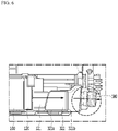
- FIG. 6 shows an enlarged portion of IV of FIG. 5 .
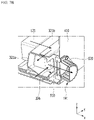
- FIG. 7a and FIG. 7b show an enlarged portion of V of FIG. 5 .
- high-pressure venting gas is discharged from the inside of the battery module 100 through the venting gate 121.
- high-temperature and high-pressure gas and flames are induced to the first connection hole 324 positioned nearest the venting gate 121 of the battery module 100 in which heat is generated.
- the high-temperature and high-pressure gas and flames input through the first connection hole 324 may be discharged to the outside through the passage formed on the venting inducing frame 300.
- the high-pressure gas and flames may be discharged through the venting gate 121, may pass through the passage 322 of the horizontal beams 320, may be directly induced to the rupture portion 500, and may be discharged to the outside.
- the heat generated by the battery module 100 on the position 1 may be discharged to the outside without giving an influence to the peripheral module.
- the high-temperature and high-pressure gas and flames are discharged through the venting gate 121, and are input to the passage 322 of the horizontal beams 320.
- the high-temperature and high-pressure gas and flames having been input to the passage 312 of the vertical beams 310 through the second connection hole 314 and having moved along the passage 312 may be induced to the horizontal beams 320 on the side where the rupture portion 500 is positioned and may be finally discharged to the outside through the rupture portion 500 through the second connection hole 314 formed on the opposite end of the corresponding vertical beams 310.
- the passage of the venting gate 121 and the passage of the rupture portion 500 may be formed to cross each other.
- the passages of the venting gate 121 and the rupture portion 500 are positioned in the same line, the high-temperature and high-pressure gas and flames having passed through the venting gate 121 are transmitted to the rupture portion 500, so the rupture side 510 shown in FIG. 7B may be easily broken and the rupture portion 500 may be damaged.
- the passage of the rupture portion 500 and the passage of the venting gate 121 cross each other, the high-temperature and high-pressure gas and flames having passed through the venting gate 121 may pass through the passage in the venting inducing frame 300 formed to be vertical to the direction of the passage of the venting gate 121, and may be induced to the rupture portion 500 formed to be vertical to the venting inducing frame 300, and the high-temperature and high-pressure gas and flames reach the rupture portion 500 according to a direction switching, so the pressure transmitted to the rupture side 510 is reduced, and the high-temperature and high-pressure gas and flames may be stably discharged to the rupture portion 500.
- a battery pack in which a quenching member is formed according to an embodiment of the present invention will now be described.
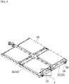
- FIG. 8 shows a perspective view in which a venting inducing frame according to an embodiment of the present invention is disposed along an edge of a plurality of battery modules.
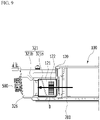
- FIG. 9 shows a portion A of FIG. 8 .
- FIG. 10 shows a portion B of FIG. 9 .
- a quenching member 122 may be formed on the passage of the venting gate 121.
- the quenching member 122 may be formed of a quenching mesh.
- the quenching mesh may be formed to have different structures and different materials depending on intensity of the flames generated from the battery cell or types of materials generated from the battery cell.
- the quenching member 122 may be formed to cover the passage of the venting gate 121. Further, it may be designed to have a predetermined thickness to sufficiently absorb the flames passing through the quenching member 122. As shown in FIG. 10 , a gate gasket 121a may be formed between the venting gate 121 and the end plate 120. The gate gasket 121a may prevent high-temperature and high-pressure gas and flames from going between the venting gate 121 and the end plate 120 by sealing a space between the venting gate 121 and the end plate 120, and may allow the same to be discharged to a specific portion through the venting inducing frame 300 and the rupture portion 500.
- FIG. 11 shows a schematic diagram on a flow of venting gas when an abnormal phenomenon is generated from a battery pack according to a comparative example.
- FIG. 12 shows a schematic diagram on a flow of venting gas when an abnormal phenomenon is generated from a battery pack according to an embodiment of the present invention.
- the conventional battery pack 20 does not have systems such as the venting gate and the venting inducing frame according to embodiments of the present invention, so the venting gas generated by the battery module 10 may be sporadically discharged.
- the venting gas in the battery module 100 when an abnormal phenomenon is generated in an initial battery cell in the battery pack 1000 according to the present embodiment, the venting gas in the battery module 100 is discharged to the outside of the battery module 100 through the venting gate 121, the venting gas in the battery pack 1000 may be controlled and safety may be increased by the system connected for each unit and inducing the venting gas by the venting inducing frame 300 including a pair of vertical beams 310 and a pair of horizontal beams 320.
- a quenching member 122 is formed for each passage of the venting gate 121 connected to the battery module 100, flames is absorbed through the quenching member 122, and gas may be discharged to the outside by the venting inducing frame 300, thereby minimizing the collateral damage outside the battery pack.
- the above-described battery module and the battery pack including the same are applicable to various types of devices.
- the devices include transport means such as electric bicycles, electric vehicles, and hybrid vehicles, but the present invention is not limited thereto, and it may be applied to various devices that use the battery module and the battery pack including the same, which also belongs to the scope of the present invention.
Landscapes
- Chemical & Material Sciences (AREA)
- Chemical Kinetics & Catalysis (AREA)
- Electrochemistry (AREA)
- General Chemical & Material Sciences (AREA)
- Battery Mounting, Suspending (AREA)
- Gas Exhaust Devices For Batteries (AREA)
Abstract
Description
- This application claims priority to and the benefit of
Korean Patent Application No. 10-2020-0052257 filed in the Korean Intellectual Property Office on April 29, 2020 - The present invention relates to a battery pack and a device including the same, and in particular, it relates to a safety-improved battery pack and a device including the same.
- Rechargeable batteries having high application characteristics and electrical characteristics such as high energy density according to their products are widely applied to battery vehicles, hybrid vehicles, and electric power storage devices driven by electric driving sources, as well as portable devices. These rechargeable batteries are attracting attention as new energy sources for improving environmental friendliness and energy efficiency in that they do not generate any by-products of energy use, as well as their primary merit that they can drastically reduce the use of fossil fuels.
- The commercially available secondary batteries include a nickel cadmium battery, a nickel hydrogen battery, a nickel zinc battery, and a lithium secondary battery, and the lithium secondary battery among them scarcely generates a memory effect compared to the nickel-based secondary battery so it is freely charged and discharged, a self-discharge rate is very low, and an energy density is high as merits.
- The lithium secondary battery generally uses a lithium-based oxide and a carbon material as a positive active material and a negative active material, respectively. The lithium secondary battery includes an electrode assembly in which a positive electrode plate and a negative electrode plate on which the positive active material and the negative active material are respectively applied are disposed with a separator therebetween, and an exterior material, that is, a battery case, for sealing and receiving the electrode assembly together with an electrolyte solution.
- In general, the lithium secondary battery may be classified into a cylindrical or square-type secondary battery of which the electrode assembly is installed in a metal can, and a pouch-type secondary battery of which the electrode assembly is installed in a pouch of an aluminum laminate sheet, depending on a shape of the exterior material.
- Recently, as needs for a large-capacity secondary battery structure increase in addition to the use as an energy storing source of the secondary battery, needs for the battery packs in a medium to large module structure in which battery modules in which a plurality of secondary batteries are coupled in series or in parallel are gathered are increasing. Capacity and outputs of the battery modules are improved by coupling a plurality of battery cells in series or in parallel and configuring a battery cell stacked body. Further, a plurality of battery modules may configure a battery pack when installed together with various control and protection systems such as a battery management system (BMS) or a cooling system.
- The battery pack has a structure in which a plurality of battery modules are combined, so when some of the battery modules receive an overvoltage or an overcurrent or they are overheated, safety and operation efficiency of the battery pack may be problematic. Particularly, while the capacity of the battery pack is in the increasing trend to improve mileage and energy inside the pack is accordingly increasing, there is a need to design a structure satisfying reinforcing safety standards and obtaining safety of vehicles and drivers. For this purpose, the need for acquiring a structure for preventing an internal thermal runaway in advance, and minimizing corresponding damages when the thermal runaway is generated, is particularly on the rise.
- The present invention has been made in an effort to provide a safety-improved battery pack and a device including the same.
- However, the objective of the present invention is not limited to the aforementioned one, and may be extended in various ways within the spirit and scope of the present invention.
- An embodiment of the present invention provides a battery pack including: a plurality of battery modules; a venting inducing frame disposed along an edge of the battery modules and forming a venting passage; and a venting gate for connecting an inside of the battery modules and the venting inducing frame, wherein a quenching member is formed on a passage of the venting gate.
- The quenching member may be made of a quenching mesh.
- The venting inducing frame may include a pair of vertical beams formed in parallel to a first direction and a pair of horizontal beams formed in parallel to a second direction traversing the first direction, and the vertical beams and the horizontal beams respectively having a pipe shape may include a cover formed in length directions of the vertical beams and the horizontal beams, and a passage surrounded by the cover and formed to allow gas to pass through.
- The battery pack may further include at least one rupture portion connected to the passage on an outside of one of the horizontal beams and the vertical beams.
- A passage of the venting gate and a passage of the rupture portion may be formed to cross each other.
- The cover of the horizontal beams may include at least one first connection hole facing the battery module, and the venting gate may be formed so that a pipe shape of the venting gate may communicate with a pipe shape of the horizontal beams facing the first connection hole.
- A second connection hole communicating with a passage of another of the vertical beams and the horizontal beams may be installed on a cover of one of the vertical beams and the horizontal beams on a portion where the vertical beams traverse the horizontal beams.
- The battery pack may further include a pack housing for receiving the battery modules and the venting inducing frame, wherein the pack housing may include an upper cover and a lower housing, and a pack gasket may be formed between the upper cover and the lower housing.
- The battery modules may include an end plate for covering a battery cell stacked body exposed on a front side and a rear side of a module frame, an opening may be formed in part of the end plate, and the venting gate may be connected to an opening of the end plate.
- A gate gasket may be formed between the venting gate and the end plate.
- Another embodiment of the present invention provides a device including the above-described battery pack.
- According to the embodiments, the venting inducing structure is provided in the battery pack, so when an abnormal phenomenon is generated in the battery cell, the safety of the battery pack may be secured by inducing venting gas in a predetermined direction.
-
-
FIG. 1 shows a battery module according to an embodiment of the present invention. -
FIG. 2 shows a perspective view of a battery module ofFIG. 1 seen from bottom to top in a z-axis direction. -
FIG. 3 shows an exploded perspective view of a battery pack according to an embodiment of the present invention. -
FIG. 4 shows an exploded perspective view of a venting inducing frame in a battery pack ofFIG. 3 . -
FIG. 5 shows a mimetic diagram of a transfer path when a thermal runaway is generated on a certain module of a battery pack according to an embodiment of the present invention. -
FIG. 6 shows an enlarged portion of IV ofFIG. 5 . -
FIG. 7a andFIG. 7b show an enlarged portion of V ofFIG. 5 . -
FIG. 8 shows a perspective view in which a venting inducing frame according to an embodiment of the present invention is disposed along an edge of a plurality of battery modules. -
FIG. 9 shows a portion of A ofFIG. 8 . -
FIG. 10 shows a portion of B ofFIG. 9 . -
FIG. 11 shows a schematic diagram on a flow of venting gas when an abnormal phenomenon is generated from a battery pack according to a comparative example. -
FIG. 12 shows a schematic diagram on a flow of venting gas when an abnormal phenomenon is generated from a battery pack according to an embodiment of the present invention. - The present invention will be described more fully hereinafter with reference to the accompanying drawings, in which embodiments of the invention are shown. As those skilled in the art would realize, the described embodiments may be modified in various different ways, all without departing from the spirit or scope of the present disclosure.
- Parts that are irrelevant to the description will be omitted to clearly describe the present invention, and the same elements will be designated by the same reference numerals throughout the specification.
- The size and thickness of each configuration shown in the drawings are arbitrarily shown for better understanding and ease of description, but the present invention is not limited thereto. In the drawings, the thickness of layers, films, panels, regions, etc., are exaggerated for clarity. For ease of description, the thicknesses of some layers and areas are exaggerated.
- It will be understood that when an element such as a layer, film, region, or substrate is referred to as being "on" another element, it can be directly on the other element or intervening elements may also be present. In contrast, when an element is referred to as being "directly on" another element, there are no intervening elements present. Further, in the specification, the word "on" or "above" means disposed on or below the object portion, and does not necessarily mean disposed on the upper side of the object portion based on a gravitational direction.
- Unless explicitly described to the contrary, the word "comprise" and variations such as "comprises" or "comprising" will be understood to imply the inclusion of stated elements but not the exclusion of any other elements.
- Further, throughout the specification, the phrase "in a plan view" means viewing a target portion from the top, and the phrase "in a cross-sectional view" means viewing a cross-section formed by vertically cutting a target portion from the side.
-
FIG. 1 shows a battery module according to an embodiment of the present invention.FIG. 2 shows a perspective view of a battery module ofFIG. 1 seen from bottom to top in a z-axis direction. - Referring to
FIG. 1 andFIG. 2 , thebattery module 100 included in the battery pack ofFIG. 1 may include a battery cell stackedbody 102 in which a plurality ofbattery cells 101 are stacked, amodule frame 108 for receiving the battery cell stackedbody 102, and anend plate 120. Thebattery cells 101 are stacked to be mutually electrically connected to each other to configure the battery cell stackedbody 102. Particularly, as shown inFIG. 1 , a plurality ofbattery cells 101 may be stacked in a direction that is parallel to the y-axis. - In this instance, the battery cell stacked
body 102 according to an embodiment of the present invention may be a large-area module including a greater number of thebattery cells 101 than the prior art. For example, 48battery cells 101 may be included perbattery module 100. Regarding the large-area module, a horizontal direction length of the battery module becomes long. In this instance, the horizontal direction length may signify a direction in which thebattery cells 101 are stacked, that is, the length in the direction that is parallel to the y-axis. - The
module frame 108 for receiving the battery cell stackedbody 102 may include anupper plate 112 and alower frame 111. Thelower frame 111 may be a U-shaped frame. The U-shaped frame may include a bottom portion and two lateral portions extending upward from respective ends of the bottom portion. The bottom portion may cover a lower side (an opposite direction of a z axis) of the battery cell stackedbody 102, and the lateral portions may cover respective lateral sides (the y-axis direction and its opposite direction) of the battery cell stackedbody 102. - The
upper plate 112 may be formed to have one plate-shaped structure for surrounding a remaining upper side (z-axis direction) excluding the lower side and the respective sides surrounded by the U-shaped frame. Theupper plate 112 and thelower frame 111 may be combined to each other by welding while corresponding corners contact each other, thereby configuring a structure for covering the battery cell stackedbody 102 from top to bottom and from right to left. The battery cell stackedbody 102 may be physically protected through theupper plate 112 and thelower frame 111. For this purpose, theupper plate 112 and thelower frame 111 may include a metallic material with predetermined rigidity. - A venting
gate 121 for communicating with an inside of thebattery module 100 and releasing a flame or heat that may be generated in the inside is disposed on theend plate 120 according to the present embodiment. The ventinggate 121 may be provided on a lower side of theend plate 120 by considering a connector connecting portion for transmitting information. The ventinggate 121 may be connected to an opening (not shown) formed on part of theend plate 120 to thus communicate with the inside of thebattery module 100. - The
module frame 108 may include amodule frame protrusion 131 formed so that the bottom portion of themodule frame 108 may extend to pass through theend plate 120. In this instance, a coolant input and output by acooling port 140 connected to an upper side of themodule frame protrusion 131 may be supplied to/discharged from aheat sink 130 through themodule frame protrusion 131. -
FIG. 3 shows an exploded perspective view of a battery pack according to an embodiment of the present invention. - Referring to
FIG. 3 , thebattery pack 1000 according to an embodiment of the present invention includes a plurality ofbattery modules 100, and aventing inducing frame 300 disposed along an edge of a plurality ofbattery modules 100. Thebattery modules 100 and theventing inducing frame 300 may be mounted on apack tray 200 and may be received in apack housing 400. Thepack housing 400 may include alower housing 410 for receiving thepack tray 200, and anupper cover 420 combined to thelower housing 410 and covering an upper side of thebattery module 100. Apack gasket 411 may be formed between theupper cover 420 and thelower housing 410 to seal the inside of thepack housing 400. - The
battery modules 100 respectively include a battery cell stacked body (not shown) disposed in themodule frame 110, and include anend plate 120 for covering the battery cell stacked body exposed to the respective ends of themodule frame 110. In this instance, one of therespective end plates 120 includes a ventinggate 121 communicating with the inside of thebattery module 100 and releasing the flame or heat that may be generated from the inside. In thebattery pack 1000, the ventinggate 121 is disposed to face an external side of thebattery pack 1000, and preferably, as shown inFIG. 3 , the ventinggate 121 may be disposed to face the external side toward the respective ends in the first direction (x-axis direction) in thebattery pack 1000. - A
venting inducing frame 300 may be disposed along the edge of all thebattery modules 100. Theventing inducing frame 300 may include a pair ofvertical beams 310 and a pair ofhorizontal beams 320 formed in a pipe shape along the respective sides of thebattery pack 1000 and respectively extending in the first direction (x-axis direction) and the second direction (y-axis direction), and they are formed to communicate with each other as a whole body. A detailed configuration of theventing inducing frame 300 will be described in a later portion of the present specification. - The
battery modules 100 and theventing inducing frame 300 may be mounted on thepack tray 200, and it may be fixed to thepack tray 200 by a fixation means if needed. Thebattery module 100, theventing inducing frame 300, and thepack tray 200 may be received in thelower housing 410. Thelower housing 410 may include a bottom side on which thepack tray 200 is disposed, and a side wall extending upward from the edge of the bottom side. Anupper cover 420 for covering the upper portion of thebattery module 100 may be combined to thelower housing 410 to protect an internal electrical field. In this instance, various control and protection systems such as a battery management system (BMS) and a cooling system together with thebattery module 100 may be installed in thepack housing 400. - At least one
rupture portion 500 for discharging heat or flame generated from the inside to the outside may be formed on one side wall of thelower housing 410. A detailed configuration of therupture portion 500 will be described in a later portion of the present specification. - A venting inducing frame of a battery pack according to an embodiment of the present invention will now be described in detail.
-
FIG. 4 shows an exploded perspective view of a venting inducing frame in a battery pack ofFIG. 3 . - Referring to
FIG. 3 andFIG. 4 , theventing inducing frame 300 is formed in a pipe shape along the respective sides of thebattery pack 1000, it may include a pair ofvertical beams 310 and a pair ofhorizontal beams 320 respectively extending in the first direction (x-axis direction) and the second direction (y-axis direction), and they are formed to communicate with each other as a whole body. - The
vertical beams 310 has a pipe shape lengthily extending in the first direction (x-axis direction), and includes acover 311 for defining an inside of the pipe shape, and apassage 312 formed inside thecover 311. Thecover 311 may include a firstinternal cover 311a disposed near thebattery module 100 in the second direction (y-axis direction), and a firstexternal cover 311b facing the same and disposed to become distant from thebattery module 100 in the second direction (y-axis direction). At least one of the firstinternal cover 311a and the firstexternal cover 311b includes a groove lengthily formed in the first direction. That is, its cross-section is formed to have a "⊏" shape (formed to have a shape in which one side is removed from a square pipe shape), and the cover of the other is combined thereto to thus define thepassage 312. However, it is not limited thereto as long as the pipe shape may be obtained by thecover 311. - The
horizontal beams 320 has a pipe shape lengthily extending in the second direction (y-axis direction), and includes acover 321 for defining an inside of the pipe shape, and apassage 322 formed inside thecover 321. Thecover 321 may include a secondinternal cover 321a disposed near thebattery module 100 in the first direction (x-axis direction), and a secondexternal cover 321b facing the same and disposed to become distant from thebattery module 100 in the first direction (x-axis direction). At least one of the secondinternal cover 321a and the secondexternal cover 321b includes a groove lengthily formed in the second direction - That is, its cross-section is formed to have a "⊏" shape (formed to have a shape in which one side is removed from a square pipe shape), and the cover of the other is combined thereto to thus define the
passage 322. Particularly, in the present embodiment, as shown inFIG. 2 , the secondinternal cover 321a and the secondexternal cover 321b may be respectively formed to have a "⊏" shaped cross-section, and by this, rigidity when thehorizontal beams 320 are assembled may be increased. However, this is not limited thereto when the pipe shape may be obtained by thecover 321. - The
horizontal beams 320 includes afirst connection hole 324 formed on the side facing thebattery module 100, that is, one side of the secondinternal cover 321a. Thefirst connection hole 324 is disposed to communicate with the ventinggate 121 of thebattery module 100. Thehorizontal beams 320 further includes athird connection hole 326 formed on the side disposed in a direction becoming distant in the second direction from thebattery module 100, that is, one side of the secondexternal cover 321b. Thethird connection hole 326 is disposed so that therupture portion 500 may communicate with thepassage 322. In this instance, the ventingpath bracket 328 may combine therupture portion 500 and thehorizontal beams 320 to guide the path for the ventinggate 121, thepassage 322 of thehorizontal beams 320, and therupture portion 500 to communicate with each other. - The
vertical beams 310 include asecond connection hole 314 formed on the firstinternal cover 311a at the respective ends disposed near thehorizontal beams 320. Thepassage 322 of thehorizontal beams 320 may communicate with thepassage 312 of thevertical beams 310 through thesecond connection hole 314. - The
rupture portion 500 is connected to thepassage 322 of thehorizontal beams 320 and includes a rupture side (510, shown inFIG. 7B ) that is broken when input gas has more than a predetermined level of pressure. Further, therupture portion 500 includes a wing portion (520, shown inFIG. 7B ) protruding from a body on which therupture side 510 is formed and combining to the side wall of thelower housing 410. Thewing portion 520 may be fixed to thelower housing 410 by use of a fastening means such as a screw. - In the present embodiment, the
rupture portion 500 is connected to thepassage 322 of thehorizontal beams 320, and therupture portion 500 is fixed with thehorizontal beams 320 and thelower housing 410, and without being limited thereto, configurations for communicating with the passage of theventing inducing frame 300 and discharging to the outside may be appropriately used. Further, the formation of tworupture portions 500 on one of the one pair ofhorizontal beams 320 is exemplified in the present embodiment, and without being limited thereto, therupture portion 500 may be installed in thehorizontal beams 320 on another side, or it may be installed in thevertical beams 310, and corresponding positions and numbers may be appropriately selected if needed. - By the above-noted configuration, the passage is formed to communicate with all components inside the
venting inducing frame 300 in a square shape configured with thevertical beams 310 and thehorizontal beams 320, and the passage communicates with the ventinggate 121 of thebattery module 100 and therupture portion 500 to induce heat and flame to the outside and minimize the influence to peripheral battery modules when a thermal runaway is generated from thebattery module 100. In this instance, the flame included in the generated high-pressure venting gas is combusted while passing through the path inside theventing inducing frame 300 and it may be discharged to the outside in a safer way. In the normal condition without a thermal runaway, theventing inducing frame 300 may function as a support frame for stably supporting thebattery module 100 and may improve stability of thebattery pack 1000. - A path for controlling a case in which issues such as overvoltage, overcurrent, or overheating are generated in some battery modules in the battery pack will now be described.
-
FIG. 5 shows a mimetic diagram of a transfer path when a thermal runaway is generated on a certain module of a battery pack according to an embodiment of the present invention.FIG. 6 shows an enlarged portion of IV ofFIG. 5 .FIG. 7a andFIG. 7b show an enlarged portion of V ofFIG. 5 . - Referring to
FIG. 3 to FIG. 7 , when abnormal phenomena (heat issues) such as overvoltage, overcurrent, or overheating are generated in thebattery module 100, high-pressure venting gas is discharged from the inside of thebattery module 100 through the ventinggate 121. In this instance, high-temperature and high-pressure gas and flames are induced to thefirst connection hole 324 positioned nearest the ventinggate 121 of thebattery module 100 in which heat is generated. The high-temperature and high-pressure gas and flames input through thefirst connection hole 324 may be discharged to the outside through the passage formed on theventing inducing frame 300. - For example, when heat is generated in the
battery module 100 disposed on the position 1 inFIG. 5 , as shown inFIG. 6 , the high-pressure gas and flames may be discharged through the ventinggate 121, may pass through thepassage 322 of thehorizontal beams 320, may be directly induced to therupture portion 500, and may be discharged to the outside. By this, the heat generated by thebattery module 100 on the position 1 may be discharged to the outside without giving an influence to the peripheral module. - Further, when heat is generated in the
battery module 100 disposed on the position 2 inFIG. 5 , as shown inFIG. 7a andFIG. 7b , the high-temperature and high-pressure gas and flames are discharged through the ventinggate 121, and are input to thepassage 322 of thehorizontal beams 320. The high-temperature and high-pressure gas and flames having been input to thepassage 312 of thevertical beams 310 through thesecond connection hole 314 and having moved along thepassage 312 may be induced to thehorizontal beams 320 on the side where therupture portion 500 is positioned and may be finally discharged to the outside through therupture portion 500 through thesecond connection hole 314 formed on the opposite end of the correspondingvertical beams 310. That is, when heat is generated in thebattery module 100, high-temperature and high-pressure gas and flames may be induced and may be finally discharged to the outside on the passage of theventing inducing frame 300 through thefirst connection hole 324 positioned the nearest the ventinggate 121 of thecorresponding battery module 100. - Referring to
FIG. 7B , the passage of the ventinggate 121 and the passage of therupture portion 500 may be formed to cross each other. When the passages of the ventinggate 121 and therupture portion 500 are positioned in the same line, the high-temperature and high-pressure gas and flames having passed through the ventinggate 121 are transmitted to therupture portion 500, so therupture side 510 shown inFIG. 7B may be easily broken and therupture portion 500 may be damaged. According to the present embodiment, the passage of therupture portion 500 and the passage of the ventinggate 121 cross each other, the high-temperature and high-pressure gas and flames having passed through the ventinggate 121 may pass through the passage in theventing inducing frame 300 formed to be vertical to the direction of the passage of the ventinggate 121, and may be induced to therupture portion 500 formed to be vertical to theventing inducing frame 300, and the high-temperature and high-pressure gas and flames reach therupture portion 500 according to a direction switching, so the pressure transmitted to therupture side 510 is reduced, and the high-temperature and high-pressure gas and flames may be stably discharged to therupture portion 500. - A battery pack in which a quenching member is formed according to an embodiment of the present invention will now be described.
-
FIG. 8 shows a perspective view in which a venting inducing frame according to an embodiment of the present invention is disposed along an edge of a plurality of battery modules.FIG. 9 shows a portion A ofFIG. 8 .FIG. 10 shows a portion B ofFIG. 9 . - According to an embodiment, a quenching
member 122 may be formed on the passage of the ventinggate 121. The quenchingmember 122 may be formed of a quenching mesh. The quenching mesh may be formed to have different structures and different materials depending on intensity of the flames generated from the battery cell or types of materials generated from the battery cell. When the quenchingmember 122 is disposed on the passage of the ventinggate 121 in a like way of the present embodiment, and gas and flames are generated from thebattery module 100, the flames may pass through the quenchingmember 122 and may then become extinct, and the gas may pass through the passages of theventing inducing frame 300 and may be discharged to therupture portion 500. Therefore, the flames are filtered by the quenchingmember 122, and the gas is discharged to the outside of the battery pack, so the secondary damage applied to the device in which the battery pack according to the present embodiment is installed may be minimized. - Referring to
FIG. 9 andFIG. 10 , the quenchingmember 122 may be formed to cover the passage of the ventinggate 121. Further, it may be designed to have a predetermined thickness to sufficiently absorb the flames passing through the quenchingmember 122. As shown inFIG. 10 , agate gasket 121a may be formed between the ventinggate 121 and theend plate 120. Thegate gasket 121a may prevent high-temperature and high-pressure gas and flames from going between the ventinggate 121 and theend plate 120 by sealing a space between the ventinggate 121 and theend plate 120, and may allow the same to be discharged to a specific portion through theventing inducing frame 300 and therupture portion 500. -
FIG. 11 shows a schematic diagram on a flow of venting gas when an abnormal phenomenon is generated from a battery pack according to a comparative example.FIG. 12 shows a schematic diagram on a flow of venting gas when an abnormal phenomenon is generated from a battery pack according to an embodiment of the present invention. - Referring to
FIG. 11 , theconventional battery pack 20 does not have systems such as the venting gate and the venting inducing frame according to embodiments of the present invention, so the venting gas generated by thebattery module 10 may be sporadically discharged. - Referring to
FIG. 12 , when an abnormal phenomenon is generated in an initial battery cell in thebattery pack 1000 according to the present embodiment, the venting gas in thebattery module 100 is discharged to the outside of thebattery module 100 through the ventinggate 121, the venting gas in thebattery pack 1000 may be controlled and safety may be increased by the system connected for each unit and inducing the venting gas by theventing inducing frame 300 including a pair ofvertical beams 310 and a pair ofhorizontal beams 320. - Further, a quenching
member 122 is formed for each passage of the ventinggate 121 connected to thebattery module 100, flames is absorbed through the quenchingmember 122, and gas may be discharged to the outside by theventing inducing frame 300, thereby minimizing the collateral damage outside the battery pack. - The above-described battery module and the battery pack including the same are applicable to various types of devices. The devices include transport means such as electric bicycles, electric vehicles, and hybrid vehicles, but the present invention is not limited thereto, and it may be applied to various devices that use the battery module and the battery pack including the same, which also belongs to the scope of the present invention.
- While this invention has been described in connection with what is presently considered to be practical embodiments, it is to be understood that the invention is not limited to the disclosed embodiments, but, on the contrary, is intended to cover various modifications and equivalent arrangements included within the spirit and scope of the appended claims.
-
- 121: venting gate
- 121a: gate gasket
- 122: quenching member
- 200: pack tray
- 300: venting inducing frame
- 310: vertical beams
- 320: horizontal beams
- 311: cover of vertical beams
- 312: passage of vertical beams
- 321: cover of horizontal beams
- 322: passage of horizontal beams
- 324: first connection hole
- 314: second connection hole
- 326: third connection hole
- 400: housing
- 500: rupture portion
Claims (11)
- A battery pack comprising:a plurality of battery modules;a venting inducing frame disposed along an edge of the battery modules and forming a venting passage; anda venting gate for connecting an inside of the battery modules and the venting inducing frame,wherein a quenching member is formed on a passage of the venting gate.
- The battery pack of claim 1, wherein
the quenching member is made of a quenching mesh. - The battery pack of claim 1, whereinthe venting inducing frame includes a pair of vertical beams formed in parallel to a first direction and a pair of horizontal beams formed in parallel to a second direction traversing the first direction, andthe vertical beams and the horizontal beams respectively having a pipe shape include a cover formed in length directions of the vertical beams and the horizontal beams, and a passage surrounded by the cover and formed to allow gas to pass through.
- The battery pack of claim 3, wherein
at least one rupture portion connected to the passage is further included on an outside of one of the horizontal beams and the vertical beams. - The battery pack of claim 4, wherein
a passage of the venting gate and a passage of the rupture portion are formed to cross each other. - The battery pack of claim 3, whereinthe cover of the horizontal beams includes at least one first connection hole facing the battery module, andthe venting gate is formed so that a pipe shape of the venting gate communicates with a pipe shape of the horizontal beams facing the first connection hole.
- The battery pack of claim 3, wherein
a second connection hole communicating with a passage of another of the vertical beams and the horizontal beams is installed on a cover of one of the vertical beams and the horizontal beams on a portion where the vertical beams traverse the horizontal beams. - The battery pack of claim 1, further comprisinga pack housing for receiving the battery modules and the venting inducing frame,wherein the pack housing includes an upper cover and a lower housing, anda pack gasket is formed between the upper cover and the lower housing.
- The battery pack of claim 1, whereinthe battery modules include an end plate for covering a battery cell stacked body exposed on a front side and a rear side of a module frame,an opening is formed in part of the end plate, andthe venting gate is connected to an opening of the end plate.
- The battery pack of claim 9, wherein
a gate gasket is formed between the venting gate and the end plate. - A device comprising a battery pack according to claim 1.
Applications Claiming Priority (2)
| Application Number | Priority Date | Filing Date | Title |
|---|---|---|---|
| KR1020200052257A KR102922132B1 (en) | 2020-04-29 | 2020-04-29 | Battery pack and device including the same |
| PCT/KR2021/004660 WO2021221351A1 (en) | 2020-04-29 | 2021-04-13 | Battery pack and device including same |
Publications (2)
| Publication Number | Publication Date |
|---|---|
| EP4040586A1 true EP4040586A1 (en) | 2022-08-10 |
| EP4040586A4 EP4040586A4 (en) | 2023-07-26 |
Family
ID=78373659
Family Applications (1)
| Application Number | Title | Priority Date | Filing Date |
|---|---|---|---|
| EP21796832.0A Pending EP4040586A4 (en) | 2020-04-29 | 2021-04-13 | BATTERY PACK AND DEVICE INCLUDING THE SAME |
Country Status (6)
| Country | Link |
|---|---|
| US (1) | US12438227B2 (en) |
| EP (1) | EP4040586A4 (en) |
| JP (1) | JP7357779B2 (en) |
| KR (1) | KR102922132B1 (en) |
| CN (1) | CN114556679B (en) |
| WO (1) | WO2021221351A1 (en) |
Cited By (1)
| Publication number | Priority date | Publication date | Assignee | Title |
|---|---|---|---|---|
| EP4586386A4 (en) * | 2023-08-30 | 2026-02-25 | Lg Energy Solution Ltd | PACKAGING BOX |
Families Citing this family (11)
| Publication number | Priority date | Publication date | Assignee | Title |
|---|---|---|---|---|
| KR102664969B1 (en) * | 2022-01-26 | 2024-05-10 | 주식회사 엘지에너지솔루션 | Battery pack and a vehicle having the same |
| WO2023239216A1 (en) * | 2022-06-10 | 2023-12-14 | 주식회사 엘지에너지솔루션 | Battery pack and vehicle comprising same |
| KR102946788B1 (en) * | 2022-07-01 | 2026-03-31 | 주식회사 엘지에너지솔루션 | Battery module, battery pack and vehicle including the same |
| CA3198980A1 (en) * | 2022-08-17 | 2024-02-17 | Stewart & Stevenson Llc | Battery protective thermal enclosure |
| KR102821850B1 (en) * | 2022-09-05 | 2025-06-26 | 주식회사 엘지에너지솔루션 | Battery pack |
| CN115832581B (en) * | 2022-11-29 | 2025-12-09 | 微宏动力系统(湖州)有限公司 | Battery module |
| CN115966837A (en) * | 2022-12-14 | 2023-04-14 | 湖北亿纬动力有限公司 | Battery pack for double-layer module |
| KR20240098779A (en) | 2022-12-21 | 2024-06-28 | 주식회사 엘지에너지솔루션 | Battery pack suitable for thermal propagation delay |
| KR20240122220A (en) | 2023-02-03 | 2024-08-12 | 주식회사 엘지에너지솔루션 | Battery pack |
| EP4439799A3 (en) * | 2023-03-31 | 2025-01-22 | Eve Energy Co., Ltd. | Lower battery mounting box and battery pack |
| KR20250072762A (en) * | 2023-11-17 | 2025-05-26 | 주식회사 엘지에너지솔루션 | Battery pack and Vehicle including the same |
Family Cites Families (25)
| Publication number | Priority date | Publication date | Assignee | Title |
|---|---|---|---|---|
| JPS5420064B2 (en) * | 1972-11-06 | 1979-07-19 | ||
| JP5338331B2 (en) * | 2008-02-04 | 2013-11-13 | パナソニック株式会社 | Battery pack and electronic device equipped with the same |
| JP5466906B2 (en) | 2009-09-18 | 2014-04-09 | パナソニック株式会社 | Battery module |
| KR101191657B1 (en) * | 2010-07-19 | 2012-10-17 | 에스비리모티브 주식회사 | Battery module |
| JP5594592B2 (en) * | 2010-09-30 | 2014-09-24 | 株式会社Gsユアサ | Battery module and battery pack |
| WO2012081137A1 (en) * | 2010-12-13 | 2012-06-21 | パナソニック株式会社 | Battery pack |
| JP2014241245A (en) | 2013-06-12 | 2014-12-25 | 三菱電機株式会社 | Battery module and process of manufacturing the same |
| US10158102B2 (en) | 2013-08-30 | 2018-12-18 | Gogoro Inc. | Portable electrical energy storage device with thermal runaway mitigation |
| KR20150031611A (en) | 2013-09-16 | 2015-03-25 | 주식회사 엘지화학 | Battery Pack Having Venting Member for Selective Penetration of Gas |
| CN203941956U (en) * | 2014-05-26 | 2014-11-12 | 宁德时代新能源科技有限公司 | The hermetically-sealed construction of battery case |
| KR101747108B1 (en) * | 2014-05-29 | 2017-06-15 | 인지컨트롤스 주식회사 | Degassing apparatus for battery pack |
| KR20170003754A (en) * | 2015-06-30 | 2017-01-10 | 인지컨트롤스 주식회사 | Battery pack |
| KR102061872B1 (en) | 2016-01-28 | 2020-01-02 | 주식회사 엘지화학 | Case for Secondary Battery Pack and Secondary Battery Pack including the same |
| SG10202010361QA (en) | 2016-04-20 | 2020-11-27 | Corvus Energy Inc | Method and apparatus for managing thermal runaway gases in a battery system |
| KR101888298B1 (en) * | 2017-02-15 | 2018-08-13 | 엘지전자 주식회사 | Battery Pack |
| KR102065099B1 (en) * | 2017-04-04 | 2020-01-10 | 주식회사 엘지화학 | Battery Pack having crash beam and drain structure |
| KR20190029477A (en) | 2017-09-11 | 2019-03-20 | 엘지전자 주식회사 | Portable air caring apparatus |
| KR102033101B1 (en) | 2017-09-27 | 2019-10-16 | 주식회사 엘지화학 | Battery module, battery pack and vehicle comprising the same |
| KR102311075B1 (en) | 2018-04-09 | 2021-10-07 | 주식회사 엘지에너지솔루션 | Battery Pack Having Pack Housing |
| KR102330378B1 (en) | 2018-04-20 | 2021-11-22 | 주식회사 엘지에너지솔루션 | Battery Pack with degassing flow path |
| US11652253B2 (en) * | 2018-08-09 | 2023-05-16 | Ford Global Technologies, Llc | Enclosure seal and sealing method |
| JP7099915B2 (en) * | 2018-09-11 | 2022-07-12 | プライムアースEvエナジー株式会社 | Battery pack cooling structure and battery pack smoke exhaust structure |
| CN210110904U (en) * | 2019-09-19 | 2020-02-21 | 宁德时代新能源科技股份有限公司 | Lower box, battery package and vehicle |
| CN112310552B (en) * | 2020-02-28 | 2023-01-31 | 宁德时代新能源科技股份有限公司 | Explosion-proof valve, battery pack and device |
| KR102930111B1 (en) * | 2020-03-11 | 2026-02-25 | 에스케이온 주식회사 | Energy Storage System |
-
2020
- 2020-04-29 KR KR1020200052257A patent/KR102922132B1/en active Active
-
2021
- 2021-04-13 EP EP21796832.0A patent/EP4040586A4/en active Pending
- 2021-04-13 WO PCT/KR2021/004660 patent/WO2021221351A1/en not_active Ceased
- 2021-04-13 JP JP2022519031A patent/JP7357779B2/en active Active
- 2021-04-13 CN CN202180005897.5A patent/CN114556679B/en active Active
- 2021-04-13 US US17/772,096 patent/US12438227B2/en active Active
Cited By (1)
| Publication number | Priority date | Publication date | Assignee | Title |
|---|---|---|---|---|
| EP4586386A4 (en) * | 2023-08-30 | 2026-02-25 | Lg Energy Solution Ltd | PACKAGING BOX |
Also Published As
| Publication number | Publication date |
|---|---|
| WO2021221351A1 (en) | 2021-11-04 |
| US12438227B2 (en) | 2025-10-07 |
| EP4040586A4 (en) | 2023-07-26 |
| KR102922132B1 (en) | 2026-02-02 |
| CN114556679A (en) | 2022-05-27 |
| JP2022550521A (en) | 2022-12-02 |
| JP7357779B2 (en) | 2023-10-06 |
| CN114556679B (en) | 2025-11-28 |
| US20220407170A1 (en) | 2022-12-22 |
| KR20210133534A (en) | 2021-11-08 |
Similar Documents
| Publication | Publication Date | Title |
|---|---|---|
| US12355099B2 (en) | Battery pack and device including the same | |
| US12438227B2 (en) | Battery pack and device including the same | |
| US20230040054A1 (en) | Battery pack and device including the same | |
| JP7482996B2 (en) | Battery pack and device including same | |
| EP4096008B1 (en) | Battery pack and device including same | |
| US20240063501A1 (en) | Battery pack and device including the same | |
| US20230046419A1 (en) | Battery pack and device including the same | |
| EP4175025A1 (en) | Battery pack and device including same | |
| US20240039084A1 (en) | Battery pack and device including the same |
Legal Events
| Date | Code | Title | Description |
|---|---|---|---|
| STAA | Information on the status of an ep patent application or granted ep patent |
Free format text: STATUS: THE INTERNATIONAL PUBLICATION HAS BEEN MADE |
|
| PUAI | Public reference made under article 153(3) epc to a published international application that has entered the european phase |
Free format text: ORIGINAL CODE: 0009012 |
|
| STAA | Information on the status of an ep patent application or granted ep patent |
Free format text: STATUS: REQUEST FOR EXAMINATION WAS MADE |
|
| 17P | Request for examination filed |
Effective date: 20220413 |
|
| AK | Designated contracting states |
Kind code of ref document: A1 Designated state(s): AL AT BE BG CH CY CZ DE DK EE ES FI FR GB GR HR HU IE IS IT LI LT LU LV MC MK MT NL NO PL PT RO RS SE SI SK SM TR |
|
| A4 | Supplementary search report drawn up and despatched |
Effective date: 20230626 |
|
| RIC1 | Information provided on ipc code assigned before grant |
Ipc: H01M 50/20 20210101ALI20230620BHEP Ipc: H01M 50/24 20210101ALI20230620BHEP Ipc: H01M 50/342 20210101ALI20230620BHEP Ipc: H01M 50/383 20210101ALI20230620BHEP Ipc: H01M 50/35 20210101AFI20230620BHEP |
|
| DAV | Request for validation of the european patent (deleted) | ||
| DAX | Request for extension of the european patent (deleted) |