EP4040626B1 - Systèmes et procédés de fonctionnement d'un actif générateur de puissance - Google Patents
Systèmes et procédés de fonctionnement d'un actif générateur de puissance Download PDFInfo
- Publication number
- EP4040626B1 EP4040626B1 EP22150058.0A EP22150058A EP4040626B1 EP 4040626 B1 EP4040626 B1 EP 4040626B1 EP 22150058 A EP22150058 A EP 22150058A EP 4040626 B1 EP4040626 B1 EP 4040626B1
- Authority
- EP
- European Patent Office
- Prior art keywords
- storage device
- energy storage
- state
- function
- esr
- Prior art date
- Legal status (The legal status is an assumption and is not a legal conclusion. Google has not performed a legal analysis and makes no representation as to the accuracy of the status listed.)
- Active
Links
Images




Classifications
-
- G—PHYSICS
- G06—COMPUTING OR CALCULATING; COUNTING
- G06Q—INFORMATION AND COMMUNICATION TECHNOLOGY [ICT] SPECIALLY ADAPTED FOR ADMINISTRATIVE, COMMERCIAL, FINANCIAL, MANAGERIAL OR SUPERVISORY PURPOSES; SYSTEMS OR METHODS SPECIALLY ADAPTED FOR ADMINISTRATIVE, COMMERCIAL, FINANCIAL, MANAGERIAL OR SUPERVISORY PURPOSES, NOT OTHERWISE PROVIDED FOR
- G06Q10/00—Administration; Management
- G06Q10/06—Resources, workflows, human or project management; Enterprise or organisation planning; Enterprise or organisation modelling
- G06Q10/063—Operations research, analysis or management
- G06Q10/0639—Performance analysis of employees; Performance analysis of enterprise or organisation operations
-
- F—MECHANICAL ENGINEERING; LIGHTING; HEATING; WEAPONS; BLASTING
- F03—MACHINES OR ENGINES FOR LIQUIDS; WIND, SPRING, OR WEIGHT MOTORS; PRODUCING MECHANICAL POWER OR A REACTIVE PROPULSIVE THRUST, NOT OTHERWISE PROVIDED FOR
- F03D—WIND MOTORS
- F03D7/00—Controlling wind motors
- F03D7/02—Controlling wind motors the wind motors having rotation axis substantially parallel to the air flow entering the rotor
- F03D7/04—Automatic control; Regulation
- F03D7/042—Automatic control; Regulation by means of an electrical or electronic controller
- F03D7/043—Automatic control; Regulation by means of an electrical or electronic controller characterised by the type of control logic
- F03D7/045—Automatic control; Regulation by means of an electrical or electronic controller characterised by the type of control logic with model-based controls
-
- F—MECHANICAL ENGINEERING; LIGHTING; HEATING; WEAPONS; BLASTING
- F03—MACHINES OR ENGINES FOR LIQUIDS; WIND, SPRING, OR WEIGHT MOTORS; PRODUCING MECHANICAL POWER OR A REACTIVE PROPULSIVE THRUST, NOT OTHERWISE PROVIDED FOR
- F03D—WIND MOTORS
- F03D17/00—Monitoring or testing of wind motors, e.g. diagnostics
-
- F—MECHANICAL ENGINEERING; LIGHTING; HEATING; WEAPONS; BLASTING
- F03—MACHINES OR ENGINES FOR LIQUIDS; WIND, SPRING, OR WEIGHT MOTORS; PRODUCING MECHANICAL POWER OR A REACTIVE PROPULSIVE THRUST, NOT OTHERWISE PROVIDED FOR
- F03D—WIND MOTORS
- F03D7/00—Controlling wind motors
- F03D7/02—Controlling wind motors the wind motors having rotation axis substantially parallel to the air flow entering the rotor
- F03D7/04—Automatic control; Regulation
- F03D7/042—Automatic control; Regulation by means of an electrical or electronic controller
- F03D7/047—Automatic control; Regulation by means of an electrical or electronic controller characterised by the controller architecture, e.g. multiple processors or data communications
-
- G—PHYSICS
- G06—COMPUTING OR CALCULATING; COUNTING
- G06Q—INFORMATION AND COMMUNICATION TECHNOLOGY [ICT] SPECIALLY ADAPTED FOR ADMINISTRATIVE, COMMERCIAL, FINANCIAL, MANAGERIAL OR SUPERVISORY PURPOSES; SYSTEMS OR METHODS SPECIALLY ADAPTED FOR ADMINISTRATIVE, COMMERCIAL, FINANCIAL, MANAGERIAL OR SUPERVISORY PURPOSES, NOT OTHERWISE PROVIDED FOR
- G06Q50/00—Information and communication technology [ICT] specially adapted for implementation of business processes of specific business sectors, e.g. utilities or tourism
- G06Q50/06—Energy or water supply
-
- H—ELECTRICITY
- H02—GENERATION; CONVERSION OR DISTRIBUTION OF ELECTRIC POWER
- H02J—ELECTRIC POWER NETWORKS; CIRCUIT ARRANGEMENTS OR SYSTEMS FOR SUPPLYING OR DISTRIBUTING ELECTRIC POWER; SYSTEMS FOR STORING ELECTRIC ENERGY
- H02J3/00—Circuit arrangements for AC mains or AC distribution networks
-
- H—ELECTRICITY
- H02—GENERATION; CONVERSION OR DISTRIBUTION OF ELECTRIC POWER
- H02J—ELECTRIC POWER NETWORKS; CIRCUIT ARRANGEMENTS OR SYSTEMS FOR SUPPLYING OR DISTRIBUTING ELECTRIC POWER; SYSTEMS FOR STORING ELECTRIC ENERGY
- H02J7/00—Circuit arrangements for charging or discharging batteries or for supplying loads from batteries
- H02J7/80—Circuit arrangements for charging or discharging batteries or for supplying loads from batteries including monitoring or indicating arrangements
- H02J7/84—Control of state of health [SOH]
-
- H—ELECTRICITY
- H02—GENERATION; CONVERSION OR DISTRIBUTION OF ELECTRIC POWER
- H02J—ELECTRIC POWER NETWORKS; CIRCUIT ARRANGEMENTS OR SYSTEMS FOR SUPPLYING OR DISTRIBUTING ELECTRIC POWER; SYSTEMS FOR STORING ELECTRIC ENERGY
- H02J7/00—Circuit arrangements for charging or discharging batteries or for supplying loads from batteries
- H02J7/90—Regulation of charging or discharging current or voltage
- H02J7/971—Regulation of charging or discharging current or voltage the charge cycle being controlled or terminated in response to non-electric parameters
-
- H—ELECTRICITY
- H02—GENERATION; CONVERSION OR DISTRIBUTION OF ELECTRIC POWER
- H02J—ELECTRIC POWER NETWORKS; CIRCUIT ARRANGEMENTS OR SYSTEMS FOR SUPPLYING OR DISTRIBUTING ELECTRIC POWER; SYSTEMS FOR STORING ELECTRIC ENERGY
- H02J7/00—Circuit arrangements for charging or discharging batteries or for supplying loads from batteries
- H02J7/90—Regulation of charging or discharging current or voltage
- H02J7/971—Regulation of charging or discharging current or voltage the charge cycle being controlled or terminated in response to non-electric parameters
- H02J7/975—Regulation of charging or discharging current or voltage the charge cycle being controlled or terminated in response to non-electric parameters in response to temperature
-
- H—ELECTRICITY
- H02—GENERATION; CONVERSION OR DISTRIBUTION OF ELECTRIC POWER
- H02J—ELECTRIC POWER NETWORKS; CIRCUIT ARRANGEMENTS OR SYSTEMS FOR SUPPLYING OR DISTRIBUTING ELECTRIC POWER; SYSTEMS FOR STORING ELECTRIC ENERGY
- H02J2101/00—Supply or distribution of decentralised, dispersed or local electric power generation
- H02J2101/20—Dispersed power generation using renewable energy sources
- H02J2101/28—Wind energy
-
- H—ELECTRICITY
- H02—GENERATION; CONVERSION OR DISTRIBUTION OF ELECTRIC POWER
- H02J—ELECTRIC POWER NETWORKS; CIRCUIT ARRANGEMENTS OR SYSTEMS FOR SUPPLYING OR DISTRIBUTING ELECTRIC POWER; SYSTEMS FOR STORING ELECTRIC ENERGY
- H02J3/00—Circuit arrangements for AC mains or AC distribution networks
- H02J3/38—Arrangements for feeding a single network from two or more generators or sources in parallel; Arrangements for feeding already energised networks from additional generators or sources in parallel
- H02J3/381—Dispersed generators
Definitions
- the present disclosure relates in general to power generating assets, and more particularly to systems and methods for determining a state-of-health rating for an energy storage device of a power generating asset.
- Power generating assets may take a variety of forms, including but not limited to assets which rely on renewable and/or nonrenewable sources of energy. Such power generating assets may generally be considered one of the cleanest, most environmentally friendly energy sources presently available.
- wind turbines have gained increased attention in this regard.
- a modern wind turbine typically includes a tower, a generator, a gearbox, a nacelle, and one or more rotor blades.
- the nacelle includes a rotor assembly coupled to the gearbox and to the generator.
- the rotor assembly and the gearbox are mounted on a bedplate support frame located within the nacelle.
- the rotor blades capture kinetic energy of wind using known airfoil principles.
- the rotor blades transmit the kinetic energy in the form of rotational energy so as to turn a shaft coupling the rotor blades to a gearbox, or if a gearbox is not used, directly to the generator.
- the generator then converts the mechanical energy to electrical energy and the electrical energy may be transmitted to a converter and/or a transformer housed within the tower and subsequently deployed to a utility grid.
- Modern wind power generation systems typically take the form of a wind farm having multiple wind turbine generators that are operable to supply power to a transmission system providing power to a power grid.
- WO2020/149288A1 describes a soh/soc detecting device for power storage element, and power storage element managing unit; Patrick T. Moseley et al.
- Certain power generating assets may also include at least one energy storage device, such as a battery or capacitor, which may serve as a backup power supply to a component of the power generating asset.
- components of the wind turbine such as pitch drive motors, may be driven by power supplied by the power grid.
- these components may be driven by the energy storage devices.
- the utilization of an energy storage device may ensure that the power generating asset may be controlled even in the absence of grid power.
- the utilization of an energy storage device coupled to the pitch drive system of the wind turbine may permit the pitching of the rotor blades toward feather in the event grid power is lost. This, in turn, may prevent an overspeed event from negatively impacting the wind turbine.
- the energy storage may be desirable to ensure that the energy storage is capable of operating when needed. As such, it may be desirable to determine a state of health of the energy storage device on a regular basis.
- the art is continuously seeking new and improved systems and methods that address the aforementioned issues.
- the present disclosure is directed to systems and methods for determining a state-of-health rating for an energy storage device of a power generating asset so as to ensure the energy storage device remains operable.
- the invention is defined by a method for operating a power generating asset with the steps of independent method claim 1.
- the method may include defining, via the controller, a plurality of temperature intervals across a nominal operating range of temperatures for the energy storage device.
- a temperature interval of the plurality of temperature intervals may correspond to the ambient temperature.
- the method may also include determining, via the controller, the nominal ESR function and the potential ESR function(s) at each temperature interval of the plurality of temperature intervals. Additionally, the method may include establishing a correlation between the actual ESR function and the state-of-health rating for the energy storage device at each temperature interval as a function of the second electrical condition of the energy storage device.
- determining the state-of-health rating for the energy storage device may also include determining the state-of-health rating corresponding to the determined actual ESR function at the ambient temperature of the energy storage device based on the correlation between the actual ESR function and the state-of-health rating.
- implementing the control action may include detecting an approach of the state-of-health rating to a state-of-health threshold and generating an alert to facilitate scheduling of a maintenance event.
- the state-change event may include a scheduled test event and/or a manipulation of the energy storage device during operation of the power generating asset.
- the scheduled test event may be accomplished in conjunction with at least one additional component test of the power generating asset and results in an updating of the state-of-health rating.
- the state-change event may include a discharging event of the energy storage device or a charging event of the energy storage device.
- determining the actual ESR function may include determining the actual ESR function as a function of the second electrical condition and independent of a first electrical condition discharge profile and a second electrical condition discharge profile.
- first and second may be used interchangeably to distinguish one component from another and are not intended to signify location or importance of the individual components.
- Coupled refers to both direct coupling, as well as indirect coupling, unless otherwise specified herein.
- the present invention is directed to systems and methods for operating a power generating asset.
- the power generating asset such as a wind turbine
- the energy storage device may, for example, be a battery, a capacitor, or other suitable energy storage device which permits the continued, or emergency, operation of the component should grid power be disrupted.
- the pitch system of the wind turbine may be equipped with an energy storage device in order to ensure that the pitch system remains operable in the event of a power failure. This, in turn, may permit the pitching of the rotor blades to feather in order to slow the wind turbine as necessary even if the power from the power grid is interrupted.
- the ability to control a component of the power generating asset regardless of whether grid power is being received may facilitate the transition of the power generating asset to a safe operating mode and, thereby serve to prevent/mitigate potential damage to the power generating asset. Therefore, it may be desirable to determine a state of health of the energy storage device in order to ensure the energy storage device may be fully operational when called upon.
- the present disclosure requires the initiation of a state-change event, such as a charge or a discharge event, for the energy storage device.
- a state-change event such as a charge or a discharge event
- the change in a first electrical condition and a second electrical condition of the energy storage device such as a change in voltage and/or current
- an actual equivalent series resistance (ESR) function for the energy storage device is determined.
- the ESR represents the internal resistance of the energy storage device as seen during a charging or discharging event.
- the magnitude of ESR may vary depending on the particular characteristics (e.g. materials used, construction quality, degree of degradation, cell chemistry, ambient temperature) of the energy storage device.
- the ESR may be compared to a nominal ESR and/or projected ESR.
- This comparison may, for example, include plotting the actual ESR function and the nominal ESR function relative to the second electrical condition (e.g. current).
- a comparison of the ESR values at a specified value of the second electrical condition may indicate a decline in the state of health of the power generating asset.
- the nominal ESR function may indicate a first ESR value
- the actual ESR function may indicate a second ESR value.
- a second ESR value which is greater than the first ESR value may be indicative of a decline in the state of health of the energy storage device.
- the ESR of the energy storage device may increase as the remaining lifespan of the energy storage device decreases. It should be appreciated that detecting this degradation in the energy storage device may facilitate the generation of an alarm and/or a maintenance schedule.
- FIG. 1 illustrates a perspective view of one embodiment of a power generating asset 100 according to the present disclosure.
- the power generating asset 100 may be configured as a wind turbine 114.
- the power generating asset 100 may, for example, be configured as a solar power generating asset, a hydroelectric plant, a fossil fuel generator, and/or a hybrid power generating asset.
- the wind turbine 114 may generally include a tower 102 extending from a support surface 104, a nacelle 106, mounted on the tower 102, and a rotor 108 coupled to the nacelle 106.
- the rotor 108 may include a rotatable hub 110 and at least one rotor blade 112 coupled to, and extending outwardly from, the hub 110.
- the rotor 108 includes three rotor blades 112.
- the rotor 108 may include more or less than three rotor blades 112.
- Each rotor blade 112 may be spaced about the hub 110 to facilitate rotating the rotor 108 to enable kinetic energy to be transferred from the wind into usable mechanical energy, and subsequently, electrical energy.
- the hub 110 may be rotatably coupled to an electric generator 118 ( FIG. 2 ) positioned within the nacelle 106 to permit electrical energy to be produced.
- the power generating asset 100 includes a controller 200.
- the controller 200 may be configured as a turbine controller centralized within the nacelle 106. However, in other embodiments, the controller 200 may be located within any other component of the wind turbine 114 or at a location outside the wind turbine 114. Further, the controller 200 may be communicatively coupled to any number of the components of the power generating asset 100 in order to control the components. As such, the controller 200 may include a computer or other suitable processing unit. Thus, in several embodiments, the controller 200 may include suitable computer-readable instructions that, when implemented, configure the controller 200 to perform various different functions, such as receiving, transmitting and/or executing wind turbine control signals.
- the generator 118 may be coupled to the rotor 108 for producing electrical power from the rotational energy generated by the rotor 108.
- the rotor 108 may include a rotor shaft 122 coupled to the hub 110 for rotation therewith.
- the rotor shaft 122 may be rotatably supported by a main bearing 144.
- the rotor shaft 122 may, in turn, be rotatably coupled to a high-speed shaft 124 of the generator 118 through a gearbox 126 connected to a bedplate support frame 136.
- the rotor shaft 122 may provide a low-speed, high-torque input to the gearbox 126 in response to rotation of the rotor blades 112 and the hub 110.
- the gearbox 126 may then be configured to convert the low-speed, high-torque input to a high-speed, low-torque output to drive the high-speed shaft 124 and, thus, the generator 118.
- Each rotor blade 112 may also include a pitch control mechanism 120 configured to rotate each rotor blade 112 about its pitch axis 116.
- Each pitch control mechanism 120 may include a pitch drive motor 128, a pitch drive gearbox 130, and a pitch drive pinion 132.
- the pitch drive motor 128 may be coupled to the pitch drive gearbox 130 so that the pitch drive motor 128 imparts mechanical force to the pitch drive gearbox 130.
- the pitch drive gearbox 130 may be coupled to the pitch drive pinion 132 for rotation therewith.
- the pitch drive pinion 132 may, in turn, be in rotational engagement with a pitch bearing 134 coupled between the hub 110 and a corresponding rotor blade 112 such that rotation of the pitch drive pinion 132 causes rotation of the pitch bearing 134.
- rotation of the pitch drive motor 128 drives the pitch drive gearbox 130 and the pitch drive pinion 132, thereby rotating the pitch bearing 134 and the rotor blade(s) 112 about the pitch axis 116.
- pitching the rotor blade(s) 112 about the pitch axis 116 may alter an angle of attack between the rotor blade(s) 112 and an apparent wind. Accordingly, the rotor blade(s)112 may pitch to feather when the rotor blade(s) 112 rotates about the pitch axis 116 towards alignment with the apparent wind and to power when the rotor blade(s) rotates towards an orientation generally perpendicular to the apparent wind. It should be further appreciated that pitching to feather generally depowers the rotor blade(s) 112 as a result of a reduction in the resultant lift.
- the wind turbine 114 may include one or more yaw drive mechanisms 138 communicatively coupled to the controller 200, with each yaw drive mechanism(s) 138 being configured to change the angle of the nacelle 106 relative to the wind (e.g., by engaging a yaw bearing 140 of the wind turbine 114).
- the controller 200 may direct the yawing of the nacelle 106 and/or the pitching of the rotor blades 112 so as to aerodynamically orient the wind turbine 114 relative to a wind acting on the wind turbine 114, thereby facilitating power production.
- the power generating asset 100 may also include an environmental sensor 156 configured for gathering data indicative of one or more environmental conditions.
- the environmental sensor 156 may be operably coupled to the controller 200.
- the environmental sensor(s) 156 may, for example, be a wind vane, an anemometer, a lidar sensor, thermometer, barometer, or any other suitable sensor.
- the data gathered by the environmental sensor(s) 156 may include measures of wind speed, wind direction, wind shear, wind gust, wind veer, atmospheric pressure, and/or ambient temperature.
- the environmental sensor(s) 156 may be mounted to the power generating asset 100 (e.g., to the nacelle 106 at a location downwind of the rotor 108).
- the environmental sensor(s) 156 may, in alternative embodiments, be coupled to, or integrated with, the rotor 108 and/or positioned within the nacelle 106. It should be appreciated that the environmental sensor(s) 156 may include a network of sensors and may be positioned away from the power generating asset 100.
- the term "monitor" and variations thereof indicates that the various sensors of the power generating asset 100 may be configured to provide a direct measurement of the parameters being monitored or an indirect measurement of such parameters.
- the sensors described herein may, for example, be used to generate signals relating to the parameter being monitored, which can then be utilized by the controller 200 to determine a condition or response of the power generating asset 100 and/or a component thereof.
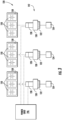
- FIG. 3 a schematic diagram of one embodiment of an energy storage device 150 operably coupled to a component 142 of the power generating asset 100 is illustrated.
- the component 142 may be configured as the pitch control mechanism 120 of the wind turbine 114.
- the component 142 may be communicatively coupled to the power grid 146.
- the component 142 may be communicatively coupled to at least one energy storage device 150.
- the energy storage device(s) 150 may be a single battery, capacitor, and/or other suitable energy storage device or pluralities thereof.
- At least one condition sensor 158 may be communicatively coupled to the energy storage device(s) 150.
- the condition sensor(s) 158 may be configured to monitor at least a first electrical condition and a second electrical condition 302, 304 ( FIG. 5 ) of the energy storage device(s) 150.
- the condition sensor(s) 158 may monitor an open-circuit voltage, an instantaneous voltage, and/or a current of the energy storage device(s) 150.
- the condition sensor(s) 158 may, in an embodiment, be an ammeter, a voltmeter, an ohmmeter, and/or any other suitable sensor for monitoring the electrical conditions 302, 304 of the energy storage device(s) 150.
- the component 142 may be driven by the power grid 146. However, in some instances, such as during an adverse grid event or grid loss, the component 142 may be powered by the energy storage device(s) 150. Therefore, in an embodiment, the energy storage device(s) 150 may be configured as an uninterrupted power supply. Accordingly, the energy storage device(s) 150 may, in an embodiment, be utilized in a top-of-charge application. For example, when configured as pitch control mechanism 120, the pitch drive motor 128 may utilize power from the energy storage device(s) 150 in order to pitch the rotor blade(s) 112 toward feather in response to an adverse grid event.
- the component 142 may be the controller 200 and the energy storage device(s) 150 may provide an uninterrupted power source to the controller 200 in response to a loss of grid power.
- the energy storage device(s) 150 may be operably coupled to the generator 118 and configured to receive at least a portion of the power output of the generator 118 and, in certain instances, deliver the received portion of the power to the power grid 146. It should be appreciated that if control of the component 142 relies on the energy storage device(s) 150 (i.e., due to a loss of grid power), it may be desirable to ensure that the energy storage device(s) 150 are capable of operating when called upon.
- the controller 200 may, in an embodiment, be configured to determine the state of health of the energy storage device(s) 150 on a regular basis.
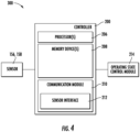
- FIGS. 4-7 multiple embodiments of a system 300 for operating the power generating asset 100, e.g. the wind turbine 114, according to the present disclosure are presented.
- the system 300 may include the controller 200 communicatively coupled to the environmental sensor(s) 156 and/or the condition sensor(s) 158.
- the controller 200 includes one or more processor(s) 206 and associated memory device(s) 208 configured to perform a variety of computer-implemented functions (e.g., performing the methods, steps, calculations and the like and storing relevant data as disclosed herein).
- the controller 200 may also include a communications module 210 to facilitate communications between the controller 200, and the various components of the power generating asset 100.
- the communications module 210 may include a sensor interface 212 (e.g., one or more analog-to-digital converters) to permit signals transmitted from the sensor(s) 156, 158 to be converted into signals that can be understood and processed by the processors 206.
- the sensor(s) 156, 158 may be communicatively coupled to the communications module 210 using any suitable means.
- the sensor(s) 156, 158 may be coupled to the sensor interface 212 via a wired connection.
- the senor(s) 156, 158 may be coupled to the sensor interface 212 via a wireless connection, such as by using any suitable wireless communications protocol known in the art.
- the communications module 210 may also be operably coupled to an operating state control module 214 configured to implement a control action based on a determination of the state of health of the energy storage device(s) 150.
- the term "processor” refers not only to integrated circuits referred to in the art as being included in a computer, but also refers to a controller, a microcontroller, a microcomputer, a programmable logic controller (PLC), an application specific integrated circuit, and other programmable circuits.
- the memory device(s) 208 may generally comprise memory element(s) including, but not limited to, computer readable medium (e.g., random access memory (RAM)), computer readable non-volatile medium (e.g., a flash memory), a floppy disk, a compact disc-read only memory (CD-ROM), a magneto-optical disk (MOD), a digital versatile disc (DVD) and/or other suitable memory elements.
- RAM random access memory
- CD-ROM compact disc-read only memory
- MOD magneto-optical disk
- DVD digital versatile disc
- Such memory device(s) 208 may generally be configured to store suitable computer-readable instructions that, when implemented by the processor(s) 206, configure the controller 200 to perform various functions including, but not limited to, operating a power generating asset 100 as described herein, as well as various other suitable computer-implemented functions.
- the controller 200 of the system 300 is configured to initiate a state-change event 306 for the energy storage device(s) 150.
- the state-change event 306 defines a plurality of sampling intervals.
- the plurality of sampling intervals may be time intervals, the sum of which may correspond to a duration of the state-change event 306.
- the controller 200 determines a change in the first and second electrical conditions 302, 304 at each of the plurality of sampling intervals of the state-change event 306. From the change in the first and second electrical conditions 302, 304, the controller 200 determines an actual equivalent series resistance (ESR) value (ESR t ) at each of the plurality of sampling intervals of the state-change event 306.
- ESR equivalent series resistance
- the controller utilizes the ESR value (ESR t ) to determine an actual ESR function 310 for the energy storage device(s) 150.
- the controller 200 may determine a state-of-health rating 312 for the energy storage device(s) 150 based on the actual ESR function 310 of the energy storage device(s) 150. Based on the state-of-health rating 312, a control action 314 is implemented.
- the state-change event 306 may be a discharge event. In an additional embodiment, the state-change event 306 may be a charging event. Accordingly, the state-change event 306 may, for example, be associated with a scheduled test event of the energy storage device(s) 150 and/or the component 142. Additionally, the state-change event 306 may, in an embodiment, be associated with a manipulation (e.g. usage) of the energy storage device(s) during an operation of the power generating asset 100. In other words, in an embodiment, the scheduled test event may be accomplished in conjunction with at least one additional component test of the power generating asset 100 and may result in an updating of the state-of-health rating 312.
- the controller 200 determines the change in the first and second electrical conditions 302, 304 which may occur during the state-change event 306.
- the change is detected, received, and/or computed at each of the sampling intervals defined by the state-change event 306. Accordingly, the change in the first and second electrical conditions 302, 304 may reflect a difference between an initial state of the first and second electrical conditions 302, 304 and a state of the electrical conditions at each of the sampling intervals.
- the first electrical condition 302 may, for example, be a voltage (V).
- determining a change in the first electrical condition 302 of the energy storage device(s) 150 may include determining a difference between an open-circuit voltage (V OC ) of the energy storage device(s) 150 and an instantaneous voltage (V t ) of the energy storage device(s) 150 at each of the plurality of sampling intervals of the state-change event 306.
- the open-circuit voltage (V OC ) may represent a no-load voltage, or a rest potential, of the energy storage device(s) 150.
- the open circuit voltage (V OC ) may depend on a state of charge of the energy storage device(s) 150.
- the open-circuit voltage (V OC ) may be considered to be a top-of-charge voltage.
- the open-circuit voltage (V OC ) may be a known/nominal value.
- the open-circuit voltage (V OC ) may be measured prior to the initiation of the state-change event 306.
- the second electrical condition 304 may, for example, be a current (I). Accordingly, determining a change in the second electrical condition 304 of the energy storage device(s) 150 may include determining a difference between the initial current (I i ) of the energy storage device(s) 150 immediately preceding the state-change event 306 and the instantaneous current (I t ) of the energy storage device(s) 150 at each of the plurality of sampling intervals of the state-change event 306. In an embodiment wherein the energy storage device(s) 150 is neither charging nor discharging prior to the initiation of the state-change event 306, the initial current (I i ) of the energy storage device(s) 150 preceding the state-change event 306 may be zero.
- the change in the current (I) may equal the instantaneous current (I t ) measured by the condition sensor(s) 158 at each of the plurality of sampling intervals during the state-change event 306.
- the initial current (I i ) may be measured by the condition sensor(s) 158 at the instant of initiation of the state-change event 306.
- the controller 200 may be configured to monitor the current (I) prior to the initiation of the state-change event 306.
- the current (I) may, in an embodiment, indicate a recharging operation for the energy storage device(s) 150.
- a current (I) above a specified threshold may indicate a degree of charging that may yield uncertainty regarding the open-circuit voltage (V OC ).
- the controller 200 may be configured to refrain from determining the state-of-health rating 312 for the state-change event 306 because uncertainty regarding the open-circuit voltage (V OC ) exists.
- a current (I) below the specified threshold may indicate that the recharging operation is complete and that the open-circuit voltage (V OC ) may be considered to be a top-of-charge voltage.
- the controller 200 may utilize the changes in the first and second electrical conditions 302, 304 to determine the corresponding ESR value (ESR t ) at each of the plurality of sampling intervals of the state-change event 306.
- the controller 200 may then utilize the ESR values (ESR t ) to determine an actual ESR function 310.
- ESR t ESR values
- the actual ESR function 310 may be a function of the second electrical condition 304 (e.g., current).
- the actual ESR function 310 may be independent of a first electrical condition 302 discharge profile and a second electrical condition 304 discharge profile.
- the ESR of the energy storage device(s) 150 may be a function of the instantaneous current (I t ).
- a degradation of the energy storage device(s) 150 may be manifest in an increasing ESR for a given second electrical condition (e.g. current).
- the controller 200 may determine a state-of-health rating 312 based on the actual ESR function 310.
- the controller 200 models a nominal ESR function 316 at an ambient temperature 318.
- the nominal ESR function 316 may represent the degree of internal resistance for a non-degraded energy storage device(s) 150. Therefore, the nominal ESR function 316 may correlate to a state-of-health rating 312 of a maximal value (e.g., 1, 100%, etc.) which may decrease with the degradation of the energy storage device(s) 150.
- the state-of-health rating 312 may be indicative of a degree of degradation and may therefore be a minimal value (e.g., 0, 0%, etc.) which may increase in proportion to an increasing degradation of the energy storage device(s) 150. It should be appreciated that when the actual ESR function 310 corresponds to the nominal ESR function 316, the state-of-health rating 312 may be considered to be a non-degraded state-of-health rating.
- the controller 200 also models at least one potential ESR function 320 at the ambient temperature 318.
- the potential ESR function(s) 320 may, as depicted in FIG. 7 , indicate an increased ESR value 322 relative to a nominal ESR value 324 as a function of the second electrical condition 304.
- the potential ESR function(s) 320 may indicate that for a given current 326, the energy storage device(s) 150 may present a greater degree of resistance (e.g., points 322) than at the nominal ESR value 324. This increase in the ESR value 322 may be indicative of a degradation of the energy storage device(s) 150.
- the potential ESR function(s) 320 may correspond to a degraded/reduced state-of-health rating 330 at the same ambient temperature 318.
- the degraded state-of-health rating 330 may represent a percentage of the maximum value (e.g., 0.9, 0.8, 0.7, etc.).
- the non-degraded state-of-health rating 328 represents a minimal value
- the degraded state-of-health rating 330 may represent a degree of degradation (e.g., 0.1, 0.2, 0.3, etc.).
- the controller 200 consolidates the nominal ESR function 316 and the potential ESR function(s) 320 into a look-up table, a graphical representation, and/or an algorithm. This consolidation may establish a correlation 334 between the actual ESR function 310 and the state-of-health rating 312 for the energy storage device(s) 150 at the ambient temperature 318 as a function of the second electrical condition 304 of the energy storage device(s) 150.
- determining the state-of-health rating 312 for the energy storage device(s) 150 may include the utilization of the look-up table, graphic orientation, and/or algorithm to determine the state-of-health rating 312 corresponding to the actual ESR function 310, which may be based off of the changes in the electrical conditions during the state-change event 306.
- the controller 200 may define a plurality of temperature intervals 336 across a nominal operating range of temperatures for the energy storage device(s) 150.
- at least one of the plurality of temperature intervals 336 may correspond to or overlap the ambient temperature 318 at the initiation of the state-change event 306.
- the plurality of temperature intervals 336 may, in an embodiment, correspond to a plurality of less than or equal to ten-degree temperature intervals 336.
- the controller 200 may determine the nominal ESR function 316 and the potential ESR function(s) 320 at each of the plurality of temperature intervals 336.
- the nominal ESR functions 316 and the potential ESR function(s)s 320 at each of the plurality of temperature intervals 336 may be assembled into a multi-dimensional, look-up table, a multi-dimensional graphical representation, and/or an algorithm.
- Such an assemblage may facilitate the establishment of a correlation between the actual ESR function 310 and the state-of-health rating 312 as a function of the second electrical condition 304 of the energy storage device(s) 150 at each temperature interval of the plurality of temperature intervals 336.
- the correlations (such as those assembled into the multi-dimensional, look-up table, a multi-dimensional graphical representation, and/or an algorithm) may be utilized to determine the state-of-health rating 312 for the energy storage device(s) 150.
- the controller 200 may correlate the state-of-health rating 312 determined for the ambient temperature to a state-of-health rating 312 at a second temperature via a correlation function.
- the state-of-health rating 312 at the second temperature may indicate a decreased capability of the energy storage device(s) 150 than is indicated for the energy storage device(s) 150 operating at the ambient temperature.
- the relationship between the state of health rating and the ambient/forecasted temperatures may be employed to predict the ability of the energy storage device(s) 150 to provide the necessary power when required during a forecasted period (e.g. winter or summer).
- the system 300 implements the control action 314 based on the state-of-health rating 312.
- the control action 314 may include generating an alert 338.
- the generation of the alert 338 may facilitate the scheduling of a maintenance event.
- the alert 338 may include an auditory signal, a visual signal, a notification, a system input, and/or any other system which may identify the state-of-health rating 312 to an operator.
- the control action 314, as described herein may further include any suitable command or constraint by the controller 200.
- the control action 314 may include temporarily de-rating the power generating asset 100.
- control action 314 may include limiting an operation of at least one component of the power generating asset.
- control action 314 may limit a pitching of a rotor blade 112 and/or a yawing of the nacelle 106 of the wind turbine 114 when the state-of-health rating 312 indicates that the energy storage device(s) 150 may not have sufficient health to respond in the expected manner when called upon.
- the controller 200 may, in an embodiment, receive a state-of-health threshold 340.
- the state-of-health threshold 340 may be indicative of a degree of degradation of the component 142 at which a control action may be desirable.
- the controller 200 may, at 342, detect an approach of the state-of-health rating 312 to the state-of-health threshold 340.
- the controller 200 may implement the control action 314 by generating the alert 338 to facilitate scheduling of the maintenance event.
- the controller 200 may determine a rate of degradation of the energy storage device(s) 150 in terms of the cycle/time count 344, 346 and utilize the rate of degradation to project a remaining service life until maintenance of the energy storage device(s) 150 is required.
- determining state-of-health rating for the energy storage device further comprises: defining, via the controller, a plurality of temperature intervals across a nominal operating range of temperatures for the energy storage device, wherein a temperature interval of the plurality of temperature intervals corresponds to the ambient temperature; modeling, via the controller, a nominal ESR function for the energy storage device at the ambient temperature, wherein the nominal ESR function corresponds to a maximal state-of-health rating at the ambient temperature; modeling, via the controller, at least one potential ESR function for the energy storage device at the ambient temperature, the at least one potential ESR function indicating an increased ESR value relative to a nominal ESR value as a function of current, the at least one potential ESR function corresponding to a reduced state-of-health rating at the ambient temperature; determining, via the controller, the nominal ESR function and the at least one potential ESR function at each temperature interval of the plurality of temperature intervals; establishing a correlation between the nominal ESR function and the at least one potential ESR function at each temperature interval as
- determining the actual ESR function further comprises determining the actual ESR function as a function of current and independent of a voltage discharge profile and a current discharge profile.
- determining a change in the voltage of the energy storage device further comprises determining a difference between an open-circuit voltage of the energy storage device and an instantaneous voltage of the energy storage device at each of the plurality of sampling intervals of the state-change event.
Landscapes
- Engineering & Computer Science (AREA)
- Business, Economics & Management (AREA)
- Power Engineering (AREA)
- Human Resources & Organizations (AREA)
- Economics (AREA)
- Sustainable Development (AREA)
- Combustion & Propulsion (AREA)
- Mechanical Engineering (AREA)
- General Engineering & Computer Science (AREA)
- Chemical & Material Sciences (AREA)
- Sustainable Energy (AREA)
- Life Sciences & Earth Sciences (AREA)
- Strategic Management (AREA)
- Health & Medical Sciences (AREA)
- Marketing (AREA)
- Theoretical Computer Science (AREA)
- Entrepreneurship & Innovation (AREA)
- Educational Administration (AREA)
- Development Economics (AREA)
- Tourism & Hospitality (AREA)
- Physics & Mathematics (AREA)
- General Business, Economics & Management (AREA)
- General Physics & Mathematics (AREA)
- General Health & Medical Sciences (AREA)
- Public Health (AREA)
- Primary Health Care (AREA)
- Water Supply & Treatment (AREA)
- Game Theory and Decision Science (AREA)
- Operations Research (AREA)
- Quality & Reliability (AREA)
- Charge And Discharge Circuits For Batteries Or The Like (AREA)
- Supply And Distribution Of Alternating Current (AREA)
- Medical Informatics (AREA)
- Secondary Cells (AREA)
Claims (13)
- Procédé permettant d'exploiter un actif de génération de puissance, l'actif de génération de puissance ayant un dispositif de stockage d'énergie couplé de manière opérationnelle à un composant de l'actif de génération de puissance, le procédé comprenant :l'initiation (306), à l'aide d'un dispositif de commande, d'un événement de changement d'état du dispositif de stockage d'énergie, l'événement de changement d'état définissant une pluralité d'intervalles d'échantillonnage ;la détermination (308), par l'intermédiaire du dispositif de commande, d'un changement dans une première condition électrique et une seconde condition électrique du dispositif de stockage d'énergie à chacun de la pluralité d'intervalles d'échantillonnage de l'événement de changement d'état ;la détermination (310), par l'intermédiaire du dispositif de commande, d'une fonction de résistance série équivalente (ESR) réelle du dispositif de stockage d'énergie sur la base du changement des première et seconde conditions électriques à chacun de la pluralité d'intervalles d'échantillonnage de l'événement de changement d'état ;la détermination (312), par l'intermédiaire du dispositif de commande, d'une évaluation d'état de santé du dispositif de stockage d'énergie sur la base de la fonction ESR réelle du dispositif de stockage d'énergie ; et la mise en œuvre (314) d'une action de commande sur la base de l'évaluation d'état de santé ; et dans lequel la détermination de l'évaluation d'état de santé du dispositif de stockage d'énergie comprend en outre :la modélisation, par l'intermédiaire du dispositif de commande, d'une fonction ESR nominale du dispositif de stockage d'énergie à une température ambiante, dans lequel la fonction ESR nominale correspond à une évaluation d'état de santé maximale à la température ambiante ;la modélisation, par l'intermédiaire du dispositif de commande, d'au moins une fonction ESR potentielle du dispositif de stockage d'énergie à la température ambiante, l'au moins une fonction ESR potentielle indiquant une valeur ESR accrue par rapport à une valeur ESR nominale en fonction de la seconde condition électrique, l'au moins une fonction ESR potentielle correspondant à une évaluation d'état de santé réduite à la température ambiante ; etla consolidation, par l'intermédiaire du dispositif de commande, de la fonction ESR nominale et de l'au moins une fonction ESR potentielle dans au moins l'un parmi une table de correspondance, une représentation graphique et un algorithme de manière à établir une corrélation entre la fonction ESR réelle et l'évaluation d'état de santé du dispositif de stockage d'énergie à la température ambiante en fonction de la seconde condition électrique du dispositif de stockage d'énergie.
- Procédé selon l'une quelconque des revendications précédentes, comprenant en outre :la définition, par l'intermédiaire du dispositif de commande, d'une pluralité d'intervalles de températures sur l'ensemble d'une plage d'exploitation nominale de températures du dispositif de stockage d'énergie, dans lequel un intervalle de températures de la pluralité d'intervalles de températures correspond à la température ambiante ;la détermination, par l'intermédiaire du dispositif de commande, de la fonction ESR nominale et de l'au moins une fonction ESR potentielle à chaque intervalle de températures de la pluralité d'intervalles de températures ; etl'établissement d'une corrélation entre la fonction ESR réelle et l'évaluation d'état de santé du dispositif de stockage d'énergie à chaque intervalle de températures en fonction de la seconde condition électrique du dispositif de stockage d'énergie.
- Procédé selon l'une quelconque des revendications précédentes, dans lequel la détermination de l'évaluation d'état de santé du dispositif de stockage d'énergie comprend en outre la détermination de l'évaluation d'état de santé correspondant à la fonction ESR réelle déterminée à la température ambiante du dispositif de stockage d'énergie sur la base de la corrélation entre la fonction ESR réelle et l'évaluation d'état de santé.
- Procédé selon l'une quelconque des revendications précédentes, dans lequel la première condition électrique comprend une tension, et dans lequel la détermination d'un changement dans la première condition électrique du dispositif de stockage d'énergie comprend en outre la détermination d'une différence entre une tension à circuit ouvert du dispositif de stockage d'énergie et une tension instantanée du dispositif de stockage d'énergie à chacun de la pluralité d'intervalles d'échantillonnage de l'événement de changement d'état.
- Procédé selon l'une quelconque des revendications précédentes, dans lequel la mise en œuvre de l'action de commande comprend en outre :le fait de détecter si l'évaluation d'état de santé se rapproche d'un seuil d'état de santé ; etla génération d'une alerte pour faciliter une programmation d'un événement de maintenance.
- Procédé selon l'une quelconque des revendications précédentes, dans lequel l'événement de changement d'état comprend au moins l'un parmi un événement de test programmé et une manipulation du dispositif de stockage d'énergie pendant une exploitation de l'actif de génération de puissance.
- Procédé selon l'une quelconque des revendications précédentes, dans lequel l'événement de test programmé est réalisé en conjonction avec au moins un test de composant supplémentaire de l'actif de génération de puissance et entraîne une mise à jour de l'évaluation d'état de santé.
- Procédé selon l'une quelconque des revendications précédentes, dans lequel l'événement de changement d'état comprend un événement de décharge du dispositif de stockage d'énergie ou un événement de charge du dispositif de stockage d'énergie.
- Procédé selon l'une quelconque des revendications précédentes, dans lequel la détermination de la fonction ESR réelle comprend en outre la détermination de la fonction ESR réelle en fonction de la seconde condition électrique et indépendamment d'un profil de décharge de première condition électrique et d'un profil de décharge de seconde condition électrique.
- Procédé selon l'une quelconque des revendications précédentes, comprenant en outre :la réception, par l'intermédiaire du dispositif de commande, d'au moins l'un parmi un nombre de cycles et une durée écoulée à partir d'une date d'installation ;la détermination, par l'intermédiaire du dispositif de commande, d'une corrélation entre l'évaluation d'état de santé et au moins l'un parmi le nombre de cycles et la durée reçus, dans lequel la corrélation indique un taux de dégradation du dispositif de stockage d'énergie par au moins l'un parmi le nombre de cycles et la durée ;la détermination d'un seuil d'état de santé du dispositif de stockage d'énergie ; etsur la base de la corrélation et du seuil d'état de santé, la détermination, par l'intermédiaire du dispositif de commande, d'au moins l'un parmi le nombre de cycles et la durée nécessaire pour atteindre le seuil d'état de santé.
- Système permettant d'exploiter un actif de génération de puissance, le système comprenant :un dispositif de stockage d'énergie couplé de manière opérationnelle à un composant de l'actif de génération de puissance ; etun dispositif de commande couplé par communication au dispositif de stockage d'énergie, le dispositif de commande comprenant au moins un processeur configuré pour effectuer une pluralité d'opérations, la pluralité d'opérations consistant à :initier (306) un événement de changement d'état du dispositif de stockage d'énergie, l'événement de changement d'état définissant une pluralité d'intervalles d'échantillonnage,déterminer (308) un changement dans une première et une seconde condition électrique du dispositif de stockage d'énergie à chacun de la pluralité d'intervalles d'échantillonnage de l'événement de changement d'état,déterminer (310) une fonction de résistance série équivalente (ESR) réelle du dispositif de stockage d'énergie sur la base du changement de la première et la seconde condition électrique à chacun de la pluralité d'intervalles d'échantillonnage de l'événement de changement d'état,déterminer (312) une évaluation d'état de santé du dispositif de stockage d'énergie sur la base de la fonction ESR réelle du dispositif de stockage d'énergie, etmettre en œuvre (314) une action de commande sur la base de l'évaluation d'état de santé ;et dans lequel la détermination de l'évaluation d'état de santé du dispositif de stockage d'énergie comprend en outre :la modélisation d'une fonction ESR nominale du dispositif de stockage d'énergie à une température ambiante, dans lequel la fonction ESR nominale correspond à une évaluation d'état de santé maximale à la température ambiante ;la modélisation d'au moins une fonction ESR potentielle du dispositif de stockage d'énergie à la température ambiante, l'au moins une fonction ESR potentielle indiquant une valeur ESR accrue par rapport à une valeur ESR nominale en fonction d'une seconde condition électrique, l'au moins une fonction ESR potentielle correspondant à une évaluation d'état de santé réduite à la température ambiante ; etla consolidation de la fonction ESR nominale et de l'au moins une fonction ESR potentielle dans au moins l'un parmi une table de correspondance, une représentation graphique et un algorithme afin d'établir une corrélation entre la fonction ESR réelle et une évaluation d'état de santé du dispositif de stockage d'énergie à la température ambiante en fonction de la seconde condition électrique du dispositif de stockage d'énergie.
- Système selon la revendication 11, la pluralité d'opérations consistant en outre à :définir une pluralité d'intervalles de températures sur l'ensemble d'une plage d'exploitation nominale de températures du dispositif de stockage d'énergie, dans lequel un intervalle de températures de la pluralité d'intervalles de températures correspond à la température ambiante ;déterminer la fonction ESR nominale et l'au moins une fonction ESR potentielle à chaque intervalle de températures de la pluralité d'intervalles de températures ; etétablir une corrélation entre la fonction ESR réelle et une évaluation d'état de santé du dispositif de stockage d'énergie à chaque intervalle de températures en fonction de la seconde condition électrique du dispositif de stockage d'énergie.
- Système selon les revendications 11 à 12, dans lequel la détermination de l'évaluation d'état de santé du dispositif de stockage d'énergie comprend en outre la détermination de l'évaluation d'état de santé correspondant à la fonction ESR réelle déterminée à la température ambiante du dispositif de stockage d'énergie sur la base de la corrélation entre la fonction ESR réelle et l'évaluation d'état de santé.
Applications Claiming Priority (1)
| Application Number | Priority Date | Filing Date | Title |
|---|---|---|---|
| US17/151,764 US12098708B2 (en) | 2021-01-19 | 2021-01-19 | Systems and methods for operating a power generating asset |
Publications (2)
| Publication Number | Publication Date |
|---|---|
| EP4040626A1 EP4040626A1 (fr) | 2022-08-10 |
| EP4040626B1 true EP4040626B1 (fr) | 2025-03-19 |
Family
ID=79185816
Family Applications (1)
| Application Number | Title | Priority Date | Filing Date |
|---|---|---|---|
| EP22150058.0A Active EP4040626B1 (fr) | 2021-01-19 | 2022-01-03 | Systèmes et procédés de fonctionnement d'un actif générateur de puissance |
Country Status (5)
| Country | Link |
|---|---|
| US (1) | US12098708B2 (fr) |
| EP (1) | EP4040626B1 (fr) |
| CN (1) | CN114819459A (fr) |
| DK (1) | DK4040626T3 (fr) |
| ES (1) | ES3033301T3 (fr) |
Families Citing this family (1)
| Publication number | Priority date | Publication date | Assignee | Title |
|---|---|---|---|---|
| JP7427944B2 (ja) * | 2019-12-06 | 2024-02-06 | 株式会社Gsユアサ | 制御装置、劣化推定システム、制御方法、及びコンピュータプログラム |
Family Cites Families (26)
| Publication number | Priority date | Publication date | Assignee | Title |
|---|---|---|---|---|
| US6462507B2 (en) * | 1998-08-07 | 2002-10-08 | Okc Products, Inc. | Apparatus and method for initial charging, self-starting, and operation of a power supply with an intermittent and/or variable energy source and a rechargeable energy storage device |
| US6469512B2 (en) | 2000-01-12 | 2002-10-22 | Honeywell International Inc. | System and method for determining battery state-of-health |
| KR100756837B1 (ko) | 2005-06-30 | 2007-09-07 | 주식회사 엘지화학 | 배터리 상태 추정 방법 및 장치 |
| KR100823507B1 (ko) | 2006-08-29 | 2008-04-21 | 삼성에스디아이 주식회사 | 배터리 관리 시스템 및 그 구동방법 |
| US8560257B2 (en) | 2010-11-29 | 2013-10-15 | GM Global Technology Operations LLC | Dynamic battery capacity estimation |
| JPWO2012091077A1 (ja) * | 2010-12-28 | 2014-06-05 | 三洋電機株式会社 | 電池の劣化度の検出方法 |
| US9157966B2 (en) | 2011-11-25 | 2015-10-13 | Honeywell International Inc. | Method and apparatus for online determination of battery state of charge and state of health |
| WO2014083856A1 (fr) * | 2012-11-30 | 2014-06-05 | 三洋電機株式会社 | Dispositif de gestion de batterie, alimentation électrique et procédé d'estimation d'état de charge |
| US9841464B2 (en) * | 2012-12-26 | 2017-12-12 | Mitsubishi Electric Corporation | Life prediction apparatus for electrical storage device and life prediction method for electrical storage device |
| EP2963728A4 (fr) * | 2013-02-26 | 2016-11-16 | Hitachi Ltd | Dispositif source d'énergie |
| US20140278170A1 (en) | 2013-03-15 | 2014-09-18 | Qualcomm Incorporated | State of charge (soc) display for rechargeable battery |
| US20140306712A1 (en) | 2013-04-12 | 2014-10-16 | Broadcom Corporation | Tracking aging effect on battery impedance and tracking battery state of health |
| EP2821640B1 (fr) * | 2013-07-05 | 2016-12-21 | Alstom Renovables España, S.L. | Systèmes et procédés de commande de pas avec une alimentation à découpage |
| CN106300407B (zh) * | 2015-05-26 | 2020-03-17 | 通用电气公司 | 发电系统 |
| KR102534623B1 (ko) * | 2015-06-01 | 2023-05-22 | 한국전자통신연구원 | 에너지 저장 장치의 건강 상태에 기반한 건물 에너지 관리 장치 및 방법 |
| WO2017000275A1 (fr) * | 2015-07-01 | 2017-01-05 | 长园科技实业股份有限公司 | Système d'alimentation électrique de batterie d'accumulation d'énergie |
| JP6554410B2 (ja) * | 2015-12-14 | 2019-07-31 | 株式会社日立製作所 | 電力貯蔵システム管理装置、電力貯蔵システム管理方法、電力貯蔵システム |
| US10720675B2 (en) * | 2016-06-07 | 2020-07-21 | Nova Lumos Ltd. | System and method for prolonging battery life |
| KR101839141B1 (ko) | 2016-10-31 | 2018-03-15 | 한국기술교육대학교 산학협력단 | 배터리 관리 시스템의 온도를 고려한 배터리의 수명 상태 예측 방법 |
| US10788538B2 (en) * | 2017-09-12 | 2020-09-29 | General Electric Company | Predictive battery test systems and methods |
| DK180754B1 (en) * | 2018-05-25 | 2022-02-24 | Kk Wind Solutions As | Wind turbine converter with integrated battery storage |
| JP7185437B2 (ja) * | 2018-07-30 | 2022-12-07 | ビークルエナジージャパン株式会社 | 電池管理装置、電池管理方法、電力貯蔵システム |
| WO2020149288A1 (fr) | 2019-01-15 | 2020-07-23 | ゴイク電池株式会社 | Dispositif de détection soh/soc pour élément de stockage d'énergie, et unité de gestion d'élément de stockage d'énergie |
| US11264807B2 (en) * | 2019-09-30 | 2022-03-01 | James Arnim White | Renewable energy metering system |
| JP7427944B2 (ja) * | 2019-12-06 | 2024-02-06 | 株式会社Gsユアサ | 制御装置、劣化推定システム、制御方法、及びコンピュータプログラム |
| DK180691B1 (en) * | 2019-12-23 | 2021-12-02 | Kk Wind Solutions As | Controlling on-time of energy modules of an energy storage |
-
2021
- 2021-01-19 US US17/151,764 patent/US12098708B2/en active Active
-
2022
- 2022-01-03 EP EP22150058.0A patent/EP4040626B1/fr active Active
- 2022-01-03 ES ES22150058T patent/ES3033301T3/es active Active
- 2022-01-03 DK DK22150058.0T patent/DK4040626T3/da active
- 2022-01-19 CN CN202210062951.6A patent/CN114819459A/zh active Pending
Also Published As
| Publication number | Publication date |
|---|---|
| US12098708B2 (en) | 2024-09-24 |
| CN114819459A (zh) | 2022-07-29 |
| DK4040626T3 (da) | 2025-06-23 |
| US20220228558A1 (en) | 2022-07-21 |
| EP4040626A1 (fr) | 2022-08-10 |
| ES3033301T3 (en) | 2025-08-01 |
Similar Documents
| Publication | Publication Date | Title |
|---|---|---|
| US10371124B2 (en) | System and method for determining wind farm wake loss | |
| US9822762B2 (en) | System and method for operating a wind turbine | |
| EP3317519B1 (fr) | Procédé et système de commande pour éoliennes | |
| EP2910777B1 (fr) | Vitesse dynamique de vent minimum de démarrage pour éoliennes | |
| CN110017249A (zh) | 运行风力涡轮的方法 | |
| EP3543523B1 (fr) | Système et procédé permettant de tester un dispositif de stockage d'énergie d'un système de pas d'éolienne | |
| EP3581795B1 (fr) | Système et procédé de commande d'éolienne pour minimiser les dommages de pales de rotor | |
| EP3406897B1 (fr) | Système et procédé de détermination de perte de sillage de parc éolien | |
| EP3454067B1 (fr) | Systèmes et procédés de test de batterie prédictive | |
| EP3249218B1 (fr) | Système et procédé d'implantation d'un parc éolien pour optimiser les charges | |
| EP3608538A1 (fr) | Solutions de remotorisation basées sur des modèles pour éoliennes | |
| EP3796016A1 (fr) | Système et procédé de détection des défauts de batterie dans un système de pas d'une éolienne | |
| EP4083421A1 (fr) | Système et procédé de détection de glissement et de surveillance de l'état de surface dans un accouplement à glissement d'un arbre rotatif | |
| US10738767B2 (en) | System and method for estimating consumed battery life of a pitch system of a wind turbine | |
| EP3722596B1 (fr) | Système et procédé pour atténuer les dommages dans une pale de rotor d'une éolienne | |
| EP4040626A1 (fr) | Systèmes et procédés de fonctionnement d'un actif générateur de puissance | |
| EP4033091A1 (fr) | Système de fonctionnement d'une éolienne à l'aide d'histogrammes de charges cumulées basés sur son fonctionnement réel | |
| EP4474925A1 (fr) | Système et procédé pour faire fonctionner de manière adaptative une centrale électrique en utilisant des points de consigne optimaux | |
| US10697432B2 (en) | Wind farm energy storage device for curtailment and auxiliary loads use | |
| US20190226456A1 (en) | System and Method for Evaluating Loads of a Potential Wind Farm Site for Multiple Wind Scenarios |
Legal Events
| Date | Code | Title | Description |
|---|---|---|---|
| PUAI | Public reference made under article 153(3) epc to a published international application that has entered the european phase |
Free format text: ORIGINAL CODE: 0009012 |
|
| STAA | Information on the status of an ep patent application or granted ep patent |
Free format text: STATUS: THE APPLICATION HAS BEEN PUBLISHED |
|
| AK | Designated contracting states |
Kind code of ref document: A1 Designated state(s): AL AT BE BG CH CY CZ DE DK EE ES FI FR GB GR HR HU IE IS IT LI LT LU LV MC MK MT NL NO PL PT RO RS SE SI SK SM TR |
|
| STAA | Information on the status of an ep patent application or granted ep patent |
Free format text: STATUS: REQUEST FOR EXAMINATION WAS MADE |
|
| 17P | Request for examination filed |
Effective date: 20230209 |
|
| RBV | Designated contracting states (corrected) |
Designated state(s): AL AT BE BG CH CY CZ DE DK EE ES FI FR GB GR HR HU IE IS IT LI LT LU LV MC MK MT NL NO PL PT RO RS SE SI SK SM TR |
|
| P01 | Opt-out of the competence of the unified patent court (upc) registered |
Effective date: 20230530 |
|
| GRAP | Despatch of communication of intention to grant a patent |
Free format text: ORIGINAL CODE: EPIDOSNIGR1 |
|
| STAA | Information on the status of an ep patent application or granted ep patent |
Free format text: STATUS: GRANT OF PATENT IS INTENDED |
|
| RIC1 | Information provided on ipc code assigned before grant |
Ipc: H02J 3/38 20060101ALN20241011BHEP Ipc: H02J 11/00 20060101ALI20241011BHEP Ipc: H02J 7/00 20060101AFI20241011BHEP |
|
| INTG | Intention to grant announced |
Effective date: 20241030 |
|
| RAP3 | Party data changed (applicant data changed or rights of an application transferred) |
Owner name: GENERAL ELECTRIC RENOVABLES ESPANA S.L. |
|
| GRAS | Grant fee paid |
Free format text: ORIGINAL CODE: EPIDOSNIGR3 |
|
| GRAA | (expected) grant |
Free format text: ORIGINAL CODE: 0009210 |
|
| STAA | Information on the status of an ep patent application or granted ep patent |
Free format text: STATUS: THE PATENT HAS BEEN GRANTED |
|
| AK | Designated contracting states |
Kind code of ref document: B1 Designated state(s): AL AT BE BG CH CY CZ DE DK EE ES FI FR GB GR HR HU IE IS IT LI LT LU LV MC MK MT NL NO PL PT RO RS SE SI SK SM TR |
|
| REG | Reference to a national code |
Ref country code: GB Ref legal event code: FG4D |
|
| REG | Reference to a national code |
Ref country code: CH Ref legal event code: EP |
|
| REG | Reference to a national code |
Ref country code: IE Ref legal event code: FG4D |
|
| REG | Reference to a national code |
Ref country code: DE Ref legal event code: R096 Ref document number: 602022011823 Country of ref document: DE |
|
| REG | Reference to a national code |
Ref country code: DK Ref legal event code: T3 Effective date: 20250616 |
|
| PG25 | Lapsed in a contracting state [announced via postgrant information from national office to epo] |
Ref country code: RS Free format text: LAPSE BECAUSE OF FAILURE TO SUBMIT A TRANSLATION OF THE DESCRIPTION OR TO PAY THE FEE WITHIN THE PRESCRIBED TIME-LIMIT Effective date: 20250619 |
|
| PG25 | Lapsed in a contracting state [announced via postgrant information from national office to epo] |
Ref country code: FI Free format text: LAPSE BECAUSE OF FAILURE TO SUBMIT A TRANSLATION OF THE DESCRIPTION OR TO PAY THE FEE WITHIN THE PRESCRIBED TIME-LIMIT Effective date: 20250319 |
|
| REG | Reference to a national code |
Ref country code: LT Ref legal event code: MG9D |
|
| PG25 | Lapsed in a contracting state [announced via postgrant information from national office to epo] |
Ref country code: NO Free format text: LAPSE BECAUSE OF FAILURE TO SUBMIT A TRANSLATION OF THE DESCRIPTION OR TO PAY THE FEE WITHIN THE PRESCRIBED TIME-LIMIT Effective date: 20250619 |
|
| PG25 | Lapsed in a contracting state [announced via postgrant information from national office to epo] |
Ref country code: HR Free format text: LAPSE BECAUSE OF FAILURE TO SUBMIT A TRANSLATION OF THE DESCRIPTION OR TO PAY THE FEE WITHIN THE PRESCRIBED TIME-LIMIT Effective date: 20250319 |
|
| PG25 | Lapsed in a contracting state [announced via postgrant information from national office to epo] |
Ref country code: LV Free format text: LAPSE BECAUSE OF FAILURE TO SUBMIT A TRANSLATION OF THE DESCRIPTION OR TO PAY THE FEE WITHIN THE PRESCRIBED TIME-LIMIT Effective date: 20250319 |
|
| PG25 | Lapsed in a contracting state [announced via postgrant information from national office to epo] |
Ref country code: GR Free format text: LAPSE BECAUSE OF FAILURE TO SUBMIT A TRANSLATION OF THE DESCRIPTION OR TO PAY THE FEE WITHIN THE PRESCRIBED TIME-LIMIT Effective date: 20250620 Ref country code: BG Free format text: LAPSE BECAUSE OF FAILURE TO SUBMIT A TRANSLATION OF THE DESCRIPTION OR TO PAY THE FEE WITHIN THE PRESCRIBED TIME-LIMIT Effective date: 20250319 |
|
| REG | Reference to a national code |
Ref country code: NL Ref legal event code: MP Effective date: 20250319 |
|
| REG | Reference to a national code |
Ref country code: ES Ref legal event code: FG2A Ref document number: 3033301 Country of ref document: ES Kind code of ref document: T3 Effective date: 20250801 |
|
| REG | Reference to a national code |
Ref country code: AT Ref legal event code: MK05 Ref document number: 1777782 Country of ref document: AT Kind code of ref document: T Effective date: 20250319 |
|
| PG25 | Lapsed in a contracting state [announced via postgrant information from national office to epo] |
Ref country code: NL Free format text: LAPSE BECAUSE OF FAILURE TO SUBMIT A TRANSLATION OF THE DESCRIPTION OR TO PAY THE FEE WITHIN THE PRESCRIBED TIME-LIMIT Effective date: 20250319 |
|
| PG25 | Lapsed in a contracting state [announced via postgrant information from national office to epo] |
Ref country code: SE Free format text: LAPSE BECAUSE OF FAILURE TO SUBMIT A TRANSLATION OF THE DESCRIPTION OR TO PAY THE FEE WITHIN THE PRESCRIBED TIME-LIMIT Effective date: 20250319 |
|
| PG25 | Lapsed in a contracting state [announced via postgrant information from national office to epo] |
Ref country code: SM Free format text: LAPSE BECAUSE OF FAILURE TO SUBMIT A TRANSLATION OF THE DESCRIPTION OR TO PAY THE FEE WITHIN THE PRESCRIBED TIME-LIMIT Effective date: 20250319 |
|
| PG25 | Lapsed in a contracting state [announced via postgrant information from national office to epo] |
Ref country code: PT Free format text: LAPSE BECAUSE OF FAILURE TO SUBMIT A TRANSLATION OF THE DESCRIPTION OR TO PAY THE FEE WITHIN THE PRESCRIBED TIME-LIMIT Effective date: 20250721 |
|
| PG25 | Lapsed in a contracting state [announced via postgrant information from national office to epo] |
Ref country code: PL Free format text: LAPSE BECAUSE OF FAILURE TO SUBMIT A TRANSLATION OF THE DESCRIPTION OR TO PAY THE FEE WITHIN THE PRESCRIBED TIME-LIMIT Effective date: 20250319 Ref country code: IT Free format text: LAPSE BECAUSE OF FAILURE TO SUBMIT A TRANSLATION OF THE DESCRIPTION OR TO PAY THE FEE WITHIN THE PRESCRIBED TIME-LIMIT Effective date: 20250319 |
|
| PG25 | Lapsed in a contracting state [announced via postgrant information from national office to epo] |
Ref country code: AT Free format text: LAPSE BECAUSE OF FAILURE TO SUBMIT A TRANSLATION OF THE DESCRIPTION OR TO PAY THE FEE WITHIN THE PRESCRIBED TIME-LIMIT Effective date: 20250319 |
|
| PG25 | Lapsed in a contracting state [announced via postgrant information from national office to epo] |
Ref country code: EE Free format text: LAPSE BECAUSE OF FAILURE TO SUBMIT A TRANSLATION OF THE DESCRIPTION OR TO PAY THE FEE WITHIN THE PRESCRIBED TIME-LIMIT Effective date: 20250319 Ref country code: CZ Free format text: LAPSE BECAUSE OF FAILURE TO SUBMIT A TRANSLATION OF THE DESCRIPTION OR TO PAY THE FEE WITHIN THE PRESCRIBED TIME-LIMIT Effective date: 20250319 |
|
| PG25 | Lapsed in a contracting state [announced via postgrant information from national office to epo] |
Ref country code: RO Free format text: LAPSE BECAUSE OF FAILURE TO SUBMIT A TRANSLATION OF THE DESCRIPTION OR TO PAY THE FEE WITHIN THE PRESCRIBED TIME-LIMIT Effective date: 20250319 |
|
| PG25 | Lapsed in a contracting state [announced via postgrant information from national office to epo] |
Ref country code: SK Free format text: LAPSE BECAUSE OF FAILURE TO SUBMIT A TRANSLATION OF THE DESCRIPTION OR TO PAY THE FEE WITHIN THE PRESCRIBED TIME-LIMIT Effective date: 20250319 |
|
| PG25 | Lapsed in a contracting state [announced via postgrant information from national office to epo] |
Ref country code: IS Free format text: LAPSE BECAUSE OF FAILURE TO SUBMIT A TRANSLATION OF THE DESCRIPTION OR TO PAY THE FEE WITHIN THE PRESCRIBED TIME-LIMIT Effective date: 20250719 |
|
| REG | Reference to a national code |
Ref country code: DE Ref legal event code: R097 Ref document number: 602022011823 Country of ref document: DE |
|
| PGFP | Annual fee paid to national office [announced via postgrant information from national office to epo] |
Ref country code: DK Payment date: 20251217 Year of fee payment: 5 |
|
| PLBE | No opposition filed within time limit |
Free format text: ORIGINAL CODE: 0009261 |
|
| STAA | Information on the status of an ep patent application or granted ep patent |
Free format text: STATUS: NO OPPOSITION FILED WITHIN TIME LIMIT |
|
| REG | Reference to a national code |
Ref country code: CH Ref legal event code: L10 Free format text: ST27 STATUS EVENT CODE: U-0-0-L10-L00 (AS PROVIDED BY THE NATIONAL OFFICE) Effective date: 20260128 |
|
| 26N | No opposition filed |
Effective date: 20251222 |
|
| PGFP | Annual fee paid to national office [announced via postgrant information from national office to epo] |
Ref country code: ES Payment date: 20260202 Year of fee payment: 5 |
|
| PGFP | Annual fee paid to national office [announced via postgrant information from national office to epo] |
Ref country code: DE Payment date: 20251217 Year of fee payment: 5 |