EP4040645A1 - Verlustarmer dämpferstab für elektrische maschinen - Google Patents
Verlustarmer dämpferstab für elektrische maschinen Download PDFInfo
- Publication number
- EP4040645A1 EP4040645A1 EP22152236.0A EP22152236A EP4040645A1 EP 4040645 A1 EP4040645 A1 EP 4040645A1 EP 22152236 A EP22152236 A EP 22152236A EP 4040645 A1 EP4040645 A1 EP 4040645A1
- Authority
- EP
- European Patent Office
- Prior art keywords
- stranded wire
- rotor
- wire damper
- conductor wires
- windings
- Prior art date
- Legal status (The legal status is an assumption and is not a legal conclusion. Google has not performed a legal analysis and makes no representation as to the accuracy of the status listed.)
- Withdrawn
Links
- 238000004804 winding Methods 0.000 claims abstract description 131
- 239000004020 conductor Substances 0.000 claims abstract description 82
- RYGMFSIKBFXOCR-UHFFFAOYSA-N Copper Chemical compound [Cu] RYGMFSIKBFXOCR-UHFFFAOYSA-N 0.000 claims description 7
- 229910052802 copper Inorganic materials 0.000 claims description 7
- 239000010949 copper Substances 0.000 claims description 7
- 229910052782 aluminium Inorganic materials 0.000 claims description 5
- XAGFODPZIPBFFR-UHFFFAOYSA-N aluminium Chemical compound [Al] XAGFODPZIPBFFR-UHFFFAOYSA-N 0.000 claims description 5
- 238000000034 method Methods 0.000 description 15
- 229910052751 metal Inorganic materials 0.000 description 13
- 239000002184 metal Substances 0.000 description 13
- 239000007787 solid Substances 0.000 description 11
- 239000012212 insulator Substances 0.000 description 9
- 238000001816 cooling Methods 0.000 description 5
- 230000009467 reduction Effects 0.000 description 5
- 230000008901 benefit Effects 0.000 description 3
- 238000004519 manufacturing process Methods 0.000 description 3
- PXHVJJICTQNCMI-UHFFFAOYSA-N Nickel Chemical compound [Ni] PXHVJJICTQNCMI-UHFFFAOYSA-N 0.000 description 2
- 229910045601 alloy Inorganic materials 0.000 description 2
- 239000000956 alloy Substances 0.000 description 2
- 238000005219 brazing Methods 0.000 description 2
- 238000000605 extraction Methods 0.000 description 2
- 238000009434 installation Methods 0.000 description 2
- 239000007788 liquid Substances 0.000 description 2
- 239000000696 magnetic material Substances 0.000 description 2
- 239000000463 material Substances 0.000 description 2
- 239000007921 spray Substances 0.000 description 2
- 229910001369 Brass Inorganic materials 0.000 description 1
- 229910000881 Cu alloy Inorganic materials 0.000 description 1
- 239000004952 Polyamide Substances 0.000 description 1
- 241000555745 Sciuridae Species 0.000 description 1
- 239000010951 brass Substances 0.000 description 1
- 239000006227 byproduct Substances 0.000 description 1
- 238000005520 cutting process Methods 0.000 description 1
- 238000013016 damping Methods 0.000 description 1
- 230000007423 decrease Effects 0.000 description 1
- 238000010586 diagram Methods 0.000 description 1
- 230000000694 effects Effects 0.000 description 1
- 230000004907 flux Effects 0.000 description 1
- 238000003780 insertion Methods 0.000 description 1
- 230000037431 insertion Effects 0.000 description 1
- 238000009413 insulation Methods 0.000 description 1
- 150000002739 metals Chemical class 0.000 description 1
- 238000012986 modification Methods 0.000 description 1
- 230000004048 modification Effects 0.000 description 1
- 229910052759 nickel Inorganic materials 0.000 description 1
- 239000012811 non-conductive material Substances 0.000 description 1
- 229920002647 polyamide Polymers 0.000 description 1
- 230000001360 synchronised effect Effects 0.000 description 1
- 238000009966 trimming Methods 0.000 description 1
Images



Classifications
-
- H—ELECTRICITY
- H02—GENERATION; CONVERSION OR DISTRIBUTION OF ELECTRIC POWER
- H02K—DYNAMO-ELECTRIC MACHINES
- H02K3/00—Details of windings
- H02K3/04—Windings characterised by the conductor shape, form or construction, e.g. with bar conductors
- H02K3/12—Windings characterised by the conductor shape, form or construction, e.g. with bar conductors arranged in slots
- H02K3/16—Windings characterised by the conductor shape, form or construction, e.g. with bar conductors arranged in slots for auxiliary purposes, e.g. damping or commutating
-
- H—ELECTRICITY
- H02—GENERATION; CONVERSION OR DISTRIBUTION OF ELECTRIC POWER
- H02K—DYNAMO-ELECTRIC MACHINES
- H02K1/00—Details of the magnetic circuit
- H02K1/06—Details of the magnetic circuit characterised by the shape, form or construction
- H02K1/22—Rotating parts of the magnetic circuit
- H02K1/26—Rotor cores with slots for windings
-
- H—ELECTRICITY
- H02—GENERATION; CONVERSION OR DISTRIBUTION OF ELECTRIC POWER
- H02K—DYNAMO-ELECTRIC MACHINES
- H02K15/00—Processes or apparatus specially adapted for manufacturing, assembling, maintaining or repairing of dynamo-electric machines
- H02K15/02—Processes or apparatus specially adapted for manufacturing, assembling, maintaining or repairing of dynamo-electric machines of stator or rotor bodies
- H02K15/021—Magnetic cores
- H02K15/023—Cage rotors
-
- H—ELECTRICITY
- H02—GENERATION; CONVERSION OR DISTRIBUTION OF ELECTRIC POWER
- H02K—DYNAMO-ELECTRIC MACHINES
- H02K19/00—Synchronous motors or generators
- H02K19/02—Synchronous motors
- H02K19/10—Synchronous motors for multi-phase current
-
- H—ELECTRICITY
- H02—GENERATION; CONVERSION OR DISTRIBUTION OF ELECTRIC POWER
- H02K—DYNAMO-ELECTRIC MACHINES
- H02K19/00—Synchronous motors or generators
- H02K19/16—Synchronous generators
- H02K19/22—Synchronous generators having windings each turn of which co-operates alternately with poles of opposite polarity, e.g. heteropolar generators
-
- H—ELECTRICITY
- H02—GENERATION; CONVERSION OR DISTRIBUTION OF ELECTRIC POWER
- H02K—DYNAMO-ELECTRIC MACHINES
- H02K3/00—Details of windings
- H02K3/02—Windings characterised by the conductor material
-
- H—ELECTRICITY
- H02—GENERATION; CONVERSION OR DISTRIBUTION OF ELECTRIC POWER
- H02K—DYNAMO-ELECTRIC MACHINES
- H02K3/00—Details of windings
- H02K3/04—Windings characterised by the conductor shape, form or construction, e.g. with bar conductors
- H02K3/12—Windings characterised by the conductor shape, form or construction, e.g. with bar conductors arranged in slots
- H02K3/14—Windings characterised by the conductor shape, form or construction, e.g. with bar conductors arranged in slots with transposed conductors, e.g. twisted conductors
-
- H—ELECTRICITY
- H02—GENERATION; CONVERSION OR DISTRIBUTION OF ELECTRIC POWER
- H02K—DYNAMO-ELECTRIC MACHINES
- H02K3/00—Details of windings
- H02K3/04—Windings characterised by the conductor shape, form or construction, e.g. with bar conductors
- H02K3/18—Windings for salient poles
- H02K3/20—Windings for salient poles for auxiliary purposes, e.g. damping or commutating
Definitions
- Typical power generators for aircraft and other vehicle are either air cooled or liquid cooled.
- Liquid cooling typically with oil can be implemented in one of three ways: spray-cooled, conduction cooled, or a combination of both spray and conduction.
- the spray cooling techniques provide very good heat extraction, but typically have the disadvantage of increased mechanical losses produced by windage in the generator. This is caused by oil being in contact with the rotor components of the generator that rotate at very high speeds. Further, these cooling systems add to the weight and size of the generator.
- High power density generators may create additional electrical losses such that traditional methods of heat extraction are ineffective within the weight and size constraints of some electric machines.
- the AC losses in the rotor caused by copper and eddy currents and proximity effect may dominate in the electrical losses of megawatt generators.
- Eddy currents are present in the damper bars used in the rotor, and depending on the generator power rating, the damper bar losses can range from hundreds of Watts to a few kW. These losses contribute to the difficulty in cooling the rotor.
- Traditional cooling systems may not be effective for continuous operation at rated power and thereby limiting significantly the capabilities of the electrical machine.
- a rotor for an electric machine includes a cylindrical central portion, and a plurality of poles extending from the cylindrical central portion in a radial direction.
- Each pole of the plurality of poles includes a top surface that includes one or more slots that are located in and extend across the top surface.
- the rotor further includes a plurality of stranded wire damper windings, wherein each stranded wire damper winding of the plurality of stranded wire damper windings includes two or more conductor wires twisted together and insulated from each other.
- the two or more conductor wires are twisted together five or more times, and each respective stranded wire damper winding of the plurality of stranded wire damper windings is positioned within a respective slot of the one or more slots of a respective pole of the plurality of poles.
- damper bars included in the rotors of an electric machine are made of a single piece of solid metal.
- the most common material for damper bars is copper, but other metals or alloys could also be used.
- the electric machines that include the damper bars can rotate at approximately 19,000 revolutions per minute and there is a large frequency of the flux (for example, approximately 1266 Hz). Due to the shape of the stator of the electric machines (includes open slots), the magnetic field is not completely uniform, and eddy currents are generated on the surface of the rotor. These high-frequency eddy currents couple into the solid metal damper bars and cause losses that are proportional to the diameter of the solid metal damper bars. It is desirable for these losses to be reduced to improve the efficiency of an electric machine, which would be particularly advantageous for the high-efficiency generators discussed above.
- the embodiments described herein provide systems and methods for reducing the losses and weight, size, and cost associated with current solid metal damper bars by using stranded wire damping windings in the rotor of an electric machine.
- the stranded wire damper windings include two or more conductor wires insulated from each other and twisted together five or more times.
- the stranded wire damper windings are included in slots in a top surface of poles of the rotor of the electric machine.
- the losses due to eddy currents can be reduced by approximately 30 to 93% compared to the solid metal damper bars.
- FIG. 1 illustrates a cross-sectional view of an example rotor 100 of an electric machine.
- the electric machine is a synchronous generator configured to produce electrical power.
- the electric machine is a motor configured to produce mechanical power when electrical power is input into terminals of the electric machine.
- the electric machine includes a housing, a stator disposed in the housing, and a rotor disposed in the stator. In such examples, there is a gap between the stator and the rotor.
- the rotor 100 includes a cylindrical central portion 102, poles 104, one or more slots 106 in each of the poles 104, stranded wire damper windings 108 in each of the one or more slots 106, and coils 110.
- the cylindrical central portion 102 of the rotor 100 rotates about a central axis, and the poles 104 extend away from the central axis of the cylindrical central portion 102 in a radial direction.
- the cylindrical central portion 102 and the poles 104 of the rotor 100 are formed of a magnetic material.
- the cylindrical central portion 102 and the poles 104 are formed of Hiperco ® 50 or a similar magnetic material.
- the rotor 100 includes coils 110 that encircle the rotor 100 and surround the poles 104 of the rotor 100.
- the coils 110 are formed of a conductive material and are held in place using a number of components.
- the coils 110 are positioned and secured using wedges 112, 114, 116 and band supports 118.
- the poles 104 of the rotor 100 each include three slots 106 in a top surface 105 of the pole 104. It should be understood that this is merely one example, and a different number of slots 106 (including one) could also be included in each of the poles 104 of the rotor 100 depending on the desired performance characteristics.
- the slots 106 in the top surface 105 of the poles 104 of the rotor 100 have an approximately circular cross-section. In the example shown in FIG.
- the slots 106 in the top surface 105 of the poles 104 of the rotor 100 also include an approximately rectangular-shaped slit between the approximately circular cross-section and the top surface 105 of the poles 104 of the rotor 100.
- the slots 106 in the top surface 105 of the poles 104 of the rotor 100 have an approximately square-shaped cross-section.
- the slots 106 in the top surface 105 of the poles 104 of the rotor 100 also include an approximately rectangular-shaped slit between the approximately squared-shaped cross-section and the top surface 105 of the poles 104 of the rotor 100.
- the slots 106 in the top surface 105 of the poles 104 of the rotor 100 can have a different shape cross-section.
- the slots 106 in the top surface 105 of the poles 104 of the rotor 100 also include an approximately rectangular-shaped slit similar to that discussed above for the circular or squared-shaped examples.
- the size of the cross-section of the slots 106 in the top surface 105 of the poles 104 of the rotor 100 depends on the rating of electric machine.
- the size of the cross-section of the slots 106 in the top surface 105 of the poles 104 of the rotor 100 increases as the power rating of the electric machine increases.
- the diameter of a circular cross-section of the slots 106 can be approximately 60 thou, and when the electric machine is a one-megawatt generator, the diameter of a circular cross-section of the slots 106 can be approximately 105 thou.
- the rotor 100 includes a stranded wire damper winding 108 in each slot 106 in the top surface 105 of the poles 104 of the rotor 100.
- the stranded wire damper winding 108 includes two or more conductor wires that are twisted together at least five times. In some examples, the conductor wires are twisted together ten or more times.
- the twisting (and particularly the higher number of twists) of the conductor wires provides both mechanical and electrical benefits. For example, the twisting of the conductor wires holds the conductor wires in place when the rotor 100 rotates at high speed (mechanical benefit) and also can aid in reducing the losses (electrical benefit).
- the conductor wires of the stranded wire damper windings 108 are formed of copper or a copper alloy (for example, including nickel). In other examples, the conductor wires are formed of aluminum, brass, or a different conductive material. The ratio of conductive materials used in the conductive winding will vary depending on performance requirements for the stranded wire damper windings 108.
- the two or more conductor wires of the stranded wire damper winding 108 are insulated from each other using an insulator.
- the insulator is formed of polyamide.
- the insulator is formed of a different insulative material. For some applications, it is desirable for the insulator to be rated for a temperature up to 240 C or higher.
- the stranded wire damper winding 108 in addition to the insulator used to insulate the conductor wires from each other, the stranded wire damper winding 108 also includes an insulator around all of the conductor wires. This additional insulator can improve ease of insertion into the slots 106 in the top surface 105 of the poles 104 of the rotor 100.
- the stranded wire damper windings 108 include two or more conductor wires.
- the conductor wires of the stranded wire damper windings 108 have a smaller diameter than the solid metal damper bars currently used.
- the particular number of conductor wires and the particular diameter of the conductor wires included in the stranded wire damper windings 108 can be selected based on a number of factors.
- the number of conductor wires and the diameter of the conductor wires can be selected based on the shape of the cross-section of the slots 106 in the top surface 105 of the poles 104 of the rotor 100, the size of the cross-section of the slots 106 in the top surface 105 of the poles 104 of the rotor 100, the desired loss performance, and/or the desired fill factor (for example, at least 60-70%) of the stranded wire damper windings 108 in the slots 106 in the top surface 105 of the poles 104 of the rotor 100. Other factors could also be used to determine the diameter of the conductor wires.
- FIG. 3 illustrates a graph showing the approximate losses in the stranded wire damper windings 108 (as a percentage of the losses in the solid metal damper bars) for different numbers of conductor wires. As shown in FIG.
- using two conductor wires in the stranded wire damper windings 108 provides an approximate 30+% reduction in losses compared to the solid metal damper bars currently used, using five or more conductor wires in the stranded wire damper windings 108 provides an approximate 80+% reduction in losses compared to the solid metal damper bars currently used, and using ten or more conductor wires in the stranded wire damper windings 108 provides an approximate 90+% reduction in losses compared to the solid metal damper bars currently used.
- the stranded wire damper windings 108 include three or four conductor wires in order to provide a better fit and fill factor inside the slots 106 in the top surface 105 of the poles 104 of the rotor 100 (for example, having an approximately circular or square-shaped cross-section).
- the stranded wire damper windings 108 include five or more conductor wires to improve loss reduction and the fill factor of the stranded wire damper windings 108 in the slots 106 in the top surface 105 of the poles 104 of the rotor 100.
- the stranded wire damper windings 108 include ten or more conductor wires, which further improves loss reduction and the fill factor of the stranded wire damper windings 108 in the slots 106 in the top surface 105 of the poles 104 of the rotor 100.
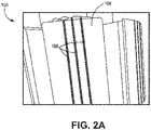
- the rotor 100 includes a conductive plate 202 coupled to each end of the rotor 100.
- the conductive plate 202 is perpendicular to the top surface 105 of the poles 104 of the rotor 100 and has a similar shape to the cross-section of the rotor 100.
- the conductive plate 202 is a copper plate.
- the conductive plate 202 is formed of a different metal (for example, aluminum) or alloy. In the examples shown in FIGS.
- the stranded wire damper windings 108 included in the slots 106 in the top surface 105 of the poles 104 of the rotor 100 are brazed (in section 204) to the conductive plate 202.
- the stranded wire damper windings 108 and the conductive plate 202 form a continuous circuit that functions as a squirrel cage.
- the conductive plate at each end of the rotor 100 is not continuous as shown in FIGS. 2A-2C .
- the conductive plate includes a slit (not shown) that separates the section 204 where the stranded wire damper windings 108 are brazed to the conductive plate and the center portion of the conductive plate.
- a non-conductive material is placed between the section where the stranded wire damper windings 108 are brazed to the conductive plate and the center portion of the conductive plate.
- an air gap is included between the section where the stranded wire damper windings 108 are brazed to the conductive plate and the center portion of the conductive plate.
- the conductive plate includes a slit that separates the section 204 where the stranded wire damper windings 108 are brazed to the conductive plate and the center portion of the conductive plate can allow for better thermal expansion and easier installation compared to the examples shown in FIGS. 2A-2C .
- the rotor 100 does not include a single conductive plate (such as conductive plate 202) at each end of the rotor 100 that connects every stranded wire damper winding 108 like the examples shown in FIGS. 2A-2C .
- the conductive plate at each end of the rotor 100 is replaced by smaller conductive plates connected to a respective pole 104 of the rotor 100 only in the section where the stranded wire damper windings 108 are brazed to the conductive plates.
- the examples where respective conductive plates are included for the section where the stranded wire damper windings 108 are brazed to the conductive plate can also allow for better thermal expansion and easier installation compared to the examples shown in FIGS. 2A-2C .
- the rotor 100 does not include any conductive plates at each end of the rotor 100 that connect the stranded wire damper windings 108.
- the stranded wire damper windings 108 for a respective pole 104 of the rotor 100 are brazed to each other without a conductive plate.
- FIG. 4 is an example method for manufacturing the stranded wire damper windings and inserting the stranded wire damper windings in a rotor.
- the common features discussed above with respect to the rotor 100 in FIGS. 1-2C can include similar characteristics to those discussed with respect to method 400 and vice versa.
- the method includes twisting conductor wires together five or more time to form a stranded wire damper winding (block 402).
- the conductor wires are coated with an insulator that provides insulation between the conductor wires.
- the conductor wires are twisted together outside of a slot in the top surface of the pole of the rotor to which the stranded wire damper windings will be included.
- the method further includes pulling the conductor wires of the stranded wire damper winding through the slot in the top surface of the pole of the rotor (block 404).
- all of the conductor wires in the stranded wire damper winding are the same length.
- the stranded wire damper winding is pulled through the slot in the top surface of the pole of the rotor using all of the conductor wires.
- one or more conductor wires are longer than the other conductor wires in the stranded wire damper winding at this stage.
- a single conductor wire is longer than the other conductor wires in the stranded wire damper winding at this stage.
- a few conductor wires are longer than the other conductor wires in the stranded wire damper winding at this stage. In either case, the conductor wire(s) that are longer are used to pull the stranded wire damper winding through the slot in the top surface of the pole of the rotor.
- the method optionally includes trimming excess length off one or more conductor wires of the stranded wire damper winding (block 406).
- the excess length is cut off so all of the conductor wires in the stranded wire damper winding are of similar length.
- the method further includes brazing the stranded wire damper windings to a conductive plate or to other stranded wire damper windings (block 408).
- all stranded wire damper windings in the same pole of the rotor are brazed to conductive plates coupled to each end of the rotor.
- the stranded wire damper windings in the same pole of the rotor are brazed to each other (without a conductive plate) at each end of the rotor.
- the size, weight, and cost of the electric machine can be reduced. Also, by using two or more conductor wires, the losses from the stranded wire damper windings are significantly reduced compared to the solid metal damper bars currently used, particularly when five or more conductor wires are included in the stranded wire damper windings.
Landscapes
- Engineering & Computer Science (AREA)
- Power Engineering (AREA)
- Manufacturing & Machinery (AREA)
- Windings For Motors And Generators (AREA)
Applications Claiming Priority (1)
| Application Number | Priority Date | Filing Date | Title |
|---|---|---|---|
| US17/170,654 US20220255384A1 (en) | 2021-02-08 | 2021-02-08 | Low losses damper bar for electric machines |
Publications (1)
| Publication Number | Publication Date |
|---|---|
| EP4040645A1 true EP4040645A1 (de) | 2022-08-10 |
Family
ID=79730378
Family Applications (1)
| Application Number | Title | Priority Date | Filing Date |
|---|---|---|---|
| EP22152236.0A Withdrawn EP4040645A1 (de) | 2021-02-08 | 2022-01-19 | Verlustarmer dämpferstab für elektrische maschinen |
Country Status (2)
| Country | Link |
|---|---|
| US (1) | US20220255384A1 (de) |
| EP (1) | EP4040645A1 (de) |
Citations (6)
| Publication number | Priority date | Publication date | Assignee | Title |
|---|---|---|---|---|
| JPS5172711U (de) * | 1974-12-04 | 1976-06-08 | ||
| DE102004038723A1 (de) * | 2004-08-06 | 2006-02-23 | Siemens Ag | Wicklung für eine elektrische Maschine mit Einzellitzen |
| US9479019B2 (en) * | 2012-01-16 | 2016-10-25 | Hamilton Sundstrand Corporation | Brushless starter generator |
| US9608551B2 (en) * | 2015-08-17 | 2017-03-28 | Abb Schweiz Ag | Reducing peak fault output current in a DC power generation system |
| US20200110133A1 (en) * | 2017-03-30 | 2020-04-09 | Abb Schweiz Ag | Method For Detecting A Rotor Bar Fault |
| US20210035706A1 (en) * | 2018-03-30 | 2021-02-04 | Furukawa Electric Co., Ltd. | Coated carbon nanotube wire for coil, coil using coated carbon nanotube wire for coil, and method for manufacturing coated carbon nanotube wire coil |
Family Cites Families (3)
| Publication number | Priority date | Publication date | Assignee | Title |
|---|---|---|---|---|
| JP5692247B2 (ja) * | 2013-01-11 | 2015-04-01 | トヨタ自動車株式会社 | モータ巻線用集合導線 |
| EP3703084A4 (de) * | 2017-10-26 | 2021-08-04 | Furukawa Electric Co., Ltd. | Kohlenstoffnanoröhrchenbeschichteter elektrischer draht und spule |
| DE102017125887A1 (de) * | 2017-11-06 | 2019-05-09 | Thyssenkrupp Ag | Verfahren und Vorrichtung zum Herstellen von Litzen, Litze und elektrische Maschine |
-
2021
- 2021-02-08 US US17/170,654 patent/US20220255384A1/en not_active Abandoned
-
2022
- 2022-01-19 EP EP22152236.0A patent/EP4040645A1/de not_active Withdrawn
Patent Citations (6)
| Publication number | Priority date | Publication date | Assignee | Title |
|---|---|---|---|---|
| JPS5172711U (de) * | 1974-12-04 | 1976-06-08 | ||
| DE102004038723A1 (de) * | 2004-08-06 | 2006-02-23 | Siemens Ag | Wicklung für eine elektrische Maschine mit Einzellitzen |
| US9479019B2 (en) * | 2012-01-16 | 2016-10-25 | Hamilton Sundstrand Corporation | Brushless starter generator |
| US9608551B2 (en) * | 2015-08-17 | 2017-03-28 | Abb Schweiz Ag | Reducing peak fault output current in a DC power generation system |
| US20200110133A1 (en) * | 2017-03-30 | 2020-04-09 | Abb Schweiz Ag | Method For Detecting A Rotor Bar Fault |
| US20210035706A1 (en) * | 2018-03-30 | 2021-02-04 | Furukawa Electric Co., Ltd. | Coated carbon nanotube wire for coil, coil using coated carbon nanotube wire for coil, and method for manufacturing coated carbon nanotube wire coil |
Also Published As
| Publication number | Publication date |
|---|---|
| US20220255384A1 (en) | 2022-08-11 |
Similar Documents
| Publication | Publication Date | Title |
|---|---|---|
| KR101530140B1 (ko) | 전기 기계용 고정자 및 전기 기계 | |
| US9559569B2 (en) | Arrangement for cooling an electric machine with a layer of thermally conducting and electrically insulating material | |
| CN105308832B (zh) | 用于高效率机械的液体冷却的定子 | |
| US3987324A (en) | High efficiency induction motor with multi-cage rotor | |
| EP0225132A1 (de) | Stator für eine elektrische Maschine | |
| US3428840A (en) | Axial air gap generator with cooling arrangement | |
| EP2401803B1 (de) | Zwei-leiter-wicklung für eine induktionsmotorschaltung | |
| HK1197321A1 (en) | Dynamoelectric device and method of forming the same | |
| JP2009171839A (ja) | スロットレスモータのための固定子巻線 | |
| Wu et al. | Investigation of an addtively-manufactured modular permanent magnet machine for high specific power design | |
| CN109301950B (zh) | 一种定子绕组及盘式电机 | |
| FI20185259A1 (en) | Electric machine stator and electric machine | |
| US20220385130A1 (en) | Rotary electric machine stator with asymmetric winding | |
| CN114123591B (zh) | 电机 | |
| US11942845B2 (en) | Stator coil for high power density and efficiency electric machines | |
| US20080054733A1 (en) | Slotless Ac Induction Motor | |
| EP4040645A1 (de) | Verlustarmer dämpferstab für elektrische maschinen | |
| EP2680404A1 (de) | Leiter für eine elektrische Maschine | |
| US20220149677A1 (en) | Stator for a rotating electrical machine | |
| EP1879279B1 (de) | Stator eines Turbogenerators | |
| US3015744A (en) | Rotor leads | |
| WO2026044480A1 (en) | Direct cooling of electric machines | |
| US7687960B2 (en) | Pigtailed stator windings for electrical generator | |
| CN223414671U (zh) | 定子总成及电机 | |
| Winterborne et al. | Winding design in high frequency electrical machines considering AC copper losses |
Legal Events
| Date | Code | Title | Description |
|---|---|---|---|
| PUAI | Public reference made under article 153(3) epc to a published international application that has entered the european phase |
Free format text: ORIGINAL CODE: 0009012 |
|
| STAA | Information on the status of an ep patent application or granted ep patent |
Free format text: STATUS: THE APPLICATION HAS BEEN PUBLISHED |
|
| AK | Designated contracting states |
Kind code of ref document: A1 Designated state(s): AL AT BE BG CH CY CZ DE DK EE ES FI FR GB GR HR HU IE IS IT LI LT LU LV MC MK MT NL NO PL PT RO RS SE SI SK SM TR |
|
| P01 | Opt-out of the competence of the unified patent court (upc) registered |
Effective date: 20230421 |
|
| STAA | Information on the status of an ep patent application or granted ep patent |
Free format text: STATUS: THE APPLICATION IS DEEMED TO BE WITHDRAWN |
|
| 18D | Application deemed to be withdrawn |
Effective date: 20230211 |