EP4040929A1 - Kabelverbindungsstruktur, einzelplatinenanordnung und verbindungsstruktur für einzelplatinenanordnung - Google Patents
Kabelverbindungsstruktur, einzelplatinenanordnung und verbindungsstruktur für einzelplatinenanordnung Download PDFInfo
- Publication number
- EP4040929A1 EP4040929A1 EP21860258.9A EP21860258A EP4040929A1 EP 4040929 A1 EP4040929 A1 EP 4040929A1 EP 21860258 A EP21860258 A EP 21860258A EP 4040929 A1 EP4040929 A1 EP 4040929A1
- Authority
- EP
- European Patent Office
- Prior art keywords
- board assembly
- board
- cable
- port
- cable connector
- Prior art date
- Legal status (The legal status is an assumption and is not a legal conclusion. Google has not performed a legal analysis and makes no representation as to the accuracy of the status listed.)
- Pending
Links
Images



Classifications
-
- H—ELECTRICITY
- H05—ELECTRIC TECHNIQUES NOT OTHERWISE PROVIDED FOR
- H05K—PRINTED CIRCUITS; CASINGS OR CONSTRUCTIONAL DETAILS OF ELECTRIC APPARATUS; MANUFACTURE OF ASSEMBLAGES OF ELECTRICAL COMPONENTS
- H05K7/00—Constructional details common to different types of electric apparatus
- H05K7/14—Mounting supporting structure in casing or on frame or rack
-
- H—ELECTRICITY
- H05—ELECTRIC TECHNIQUES NOT OTHERWISE PROVIDED FOR
- H05K—PRINTED CIRCUITS; CASINGS OR CONSTRUCTIONAL DETAILS OF ELECTRIC APPARATUS; MANUFACTURE OF ASSEMBLAGES OF ELECTRICAL COMPONENTS
- H05K7/00—Constructional details common to different types of electric apparatus
- H05K7/14—Mounting supporting structure in casing or on frame or rack
- H05K7/1422—Printed circuit boards receptacles, e.g. stacked structures, electronic circuit modules or box like frames
-
- H—ELECTRICITY
- H05—ELECTRIC TECHNIQUES NOT OTHERWISE PROVIDED FOR
- H05K—PRINTED CIRCUITS; CASINGS OR CONSTRUCTIONAL DETAILS OF ELECTRIC APPARATUS; MANUFACTURE OF ASSEMBLAGES OF ELECTRICAL COMPONENTS
- H05K7/00—Constructional details common to different types of electric apparatus
- H05K7/14—Mounting supporting structure in casing or on frame or rack
- H05K7/1438—Back panels or connecting means therefor; Terminals; Coding means to avoid wrong insertion
- H05K7/1439—Back panel mother boards
- H05K7/1441—Back panel mother boards with a segmented structure
-
- H—ELECTRICITY
- H01—ELECTRIC ELEMENTS
- H01R—ELECTRICALLY-CONDUCTIVE CONNECTIONS; STRUCTURAL ASSOCIATIONS OF A PLURALITY OF MUTUALLY-INSULATED ELECTRICAL CONNECTING ELEMENTS; COUPLING DEVICES; CURRENT COLLECTORS
- H01R12/00—Structural associations of a plurality of mutually-insulated electrical connecting elements, specially adapted for printed circuits, e.g. printed circuit boards [PCB], flat or ribbon cables, or like generally planar structures, e.g. terminal strips, terminal blocks; Coupling devices specially adapted for printed circuits, flat or ribbon cables, or like generally planar structures; Terminals specially adapted for contact with, or insertion into, printed circuits, flat or ribbon cables, or like generally planar structures
- H01R12/50—Fixed connections
- H01R12/51—Fixed connections for rigid printed circuits or like structures
- H01R12/55—Fixed connections for rigid printed circuits or like structures characterised by the terminals
- H01R12/57—Fixed connections for rigid printed circuits or like structures characterised by the terminals surface mounting terminals
-
- H—ELECTRICITY
- H01—ELECTRIC ELEMENTS
- H01R—ELECTRICALLY-CONDUCTIVE CONNECTIONS; STRUCTURAL ASSOCIATIONS OF A PLURALITY OF MUTUALLY-INSULATED ELECTRICAL CONNECTING ELEMENTS; COUPLING DEVICES; CURRENT COLLECTORS
- H01R12/00—Structural associations of a plurality of mutually-insulated electrical connecting elements, specially adapted for printed circuits, e.g. printed circuit boards [PCB], flat or ribbon cables, or like generally planar structures, e.g. terminal strips, terminal blocks; Coupling devices specially adapted for printed circuits, flat or ribbon cables, or like generally planar structures; Terminals specially adapted for contact with, or insertion into, printed circuits, flat or ribbon cables, or like generally planar structures
- H01R12/70—Coupling devices
- H01R12/71—Coupling devices for rigid printing circuits or like structures
- H01R12/75—Coupling devices for rigid printing circuits or like structures connecting to cables except for flat or ribbon cables
-
- H—ELECTRICITY
- H01—ELECTRIC ELEMENTS
- H01R—ELECTRICALLY-CONDUCTIVE CONNECTIONS; STRUCTURAL ASSOCIATIONS OF A PLURALITY OF MUTUALLY-INSULATED ELECTRICAL CONNECTING ELEMENTS; COUPLING DEVICES; CURRENT COLLECTORS
- H01R25/00—Coupling parts adapted for simultaneous co-operation with two or more identical counterparts, e.g. for distributing energy to two or more circuits
- H01R25/006—Coupling parts adapted for simultaneous co-operation with two or more identical counterparts, e.g. for distributing energy to two or more circuits the coupling part being secured to apparatus or structure, e.g. duplex wall receptacle
-
- H—ELECTRICITY
- H05—ELECTRIC TECHNIQUES NOT OTHERWISE PROVIDED FOR
- H05K—PRINTED CIRCUITS; CASINGS OR CONSTRUCTIONAL DETAILS OF ELECTRIC APPARATUS; MANUFACTURE OF ASSEMBLAGES OF ELECTRICAL COMPONENTS
- H05K7/00—Constructional details common to different types of electric apparatus
- H05K7/14—Mounting supporting structure in casing or on frame or rack
- H05K7/1401—Mounting supporting structure in casing or on frame or rack comprising clamping or extracting means
-
- H—ELECTRICITY
- H05—ELECTRIC TECHNIQUES NOT OTHERWISE PROVIDED FOR
- H05K—PRINTED CIRCUITS; CASINGS OR CONSTRUCTIONAL DETAILS OF ELECTRIC APPARATUS; MANUFACTURE OF ASSEMBLAGES OF ELECTRICAL COMPONENTS
- H05K7/00—Constructional details common to different types of electric apparatus
- H05K7/14—Mounting supporting structure in casing or on frame or rack
- H05K7/1417—Mounting supporting structure in casing or on frame or rack having securing means for mounting boards, plates or wiring boards
-
- H—ELECTRICITY
- H05—ELECTRIC TECHNIQUES NOT OTHERWISE PROVIDED FOR
- H05K—PRINTED CIRCUITS; CASINGS OR CONSTRUCTIONAL DETAILS OF ELECTRIC APPARATUS; MANUFACTURE OF ASSEMBLAGES OF ELECTRICAL COMPONENTS
- H05K7/00—Constructional details common to different types of electric apparatus
- H05K7/14—Mounting supporting structure in casing or on frame or rack
- H05K7/1438—Back panels or connecting means therefor; Terminals; Coding means to avoid wrong insertion
- H05K7/1439—Back panel mother boards
- H05K7/1444—Complex or three-dimensional-arrangements; Stepped or dual mother boards
-
- H—ELECTRICITY
- H05—ELECTRIC TECHNIQUES NOT OTHERWISE PROVIDED FOR
- H05K—PRINTED CIRCUITS; CASINGS OR CONSTRUCTIONAL DETAILS OF ELECTRIC APPARATUS; MANUFACTURE OF ASSEMBLAGES OF ELECTRICAL COMPONENTS
- H05K7/00—Constructional details common to different types of electric apparatus
- H05K7/14—Mounting supporting structure in casing or on frame or rack
- H05K7/1438—Back panels or connecting means therefor; Terminals; Coding means to avoid wrong insertion
- H05K7/1439—Back panel mother boards
- H05K7/1445—Back panel mother boards with double-sided connections
-
- H—ELECTRICITY
- H05—ELECTRIC TECHNIQUES NOT OTHERWISE PROVIDED FOR
- H05K—PRINTED CIRCUITS; CASINGS OR CONSTRUCTIONAL DETAILS OF ELECTRIC APPARATUS; MANUFACTURE OF ASSEMBLAGES OF ELECTRICAL COMPONENTS
- H05K7/00—Constructional details common to different types of electric apparatus
- H05K7/14—Mounting supporting structure in casing or on frame or rack
- H05K7/1438—Back panels or connecting means therefor; Terminals; Coding means to avoid wrong insertion
- H05K7/1447—External wirings; Wiring ducts; Laying cables
-
- H—ELECTRICITY
- H05—ELECTRIC TECHNIQUES NOT OTHERWISE PROVIDED FOR
- H05K—PRINTED CIRCUITS; CASINGS OR CONSTRUCTIONAL DETAILS OF ELECTRIC APPARATUS; MANUFACTURE OF ASSEMBLAGES OF ELECTRICAL COMPONENTS
- H05K7/00—Constructional details common to different types of electric apparatus
- H05K7/14—Mounting supporting structure in casing or on frame or rack
- H05K7/1438—Back panels or connecting means therefor; Terminals; Coding means to avoid wrong insertion
- H05K7/1452—Mounting of connectors; Switching; Reinforcing of back panels
-
- H—ELECTRICITY
- H01—ELECTRIC ELEMENTS
- H01R—ELECTRICALLY-CONDUCTIVE CONNECTIONS; STRUCTURAL ASSOCIATIONS OF A PLURALITY OF MUTUALLY-INSULATED ELECTRICAL CONNECTING ELEMENTS; COUPLING DEVICES; CURRENT COLLECTORS
- H01R12/00—Structural associations of a plurality of mutually-insulated electrical connecting elements, specially adapted for printed circuits, e.g. printed circuit boards [PCB], flat or ribbon cables, or like generally planar structures, e.g. terminal strips, terminal blocks; Coupling devices specially adapted for printed circuits, flat or ribbon cables, or like generally planar structures; Terminals specially adapted for contact with, or insertion into, printed circuits, flat or ribbon cables, or like generally planar structures
- H01R12/70—Coupling devices
- H01R12/7005—Guiding, mounting, polarizing or locking means; Extractors
- H01R12/7011—Locking or fixing a connector to a PCB
Definitions
- Embodiments of the disclosure relate to, but are not limited to, the field of communications technologies, and in particular to a cable connection structure, a single-board assembly, and a single-board assembly connection structure.
- PCB Printed Circuit Board
- connection structure such as a connector
- Embodiments of the disclosure provide a cable connection structure, a single-board assembly and a single-board assembly connection structure.
- a cable connection structure including: a bearing member, the bearing member being provided with at least one cable connector, and each cable connector having a first port connected to a cable and a second port electrically connected to the first port; and a sliding structure connected to the bearing member, the bearing member being configured to be connected to a single board through the sliding structure, the bearing member enabling the single board connected to the bearing member to slide in a first direction which is a direction close to or away from the second port.
- the bearing member is formed as a plate shape and is provided with a plurality of cable connectors, and the plurality of cable connectors are arranged sequentially in a direction perpendicular to the first direction.
- the cable connection structure further incudes a sliding lock, the sliding lock being configured to fix the sliding structure relative to the bearing member.
- a single-board assembly including a single board and any one of cable connection structures as set forth above, wherein the single board is slidably connected to the bearing member through the sliding structure; the single board includes at least one cable interface; and the single-board assembly further includes the cable connected between the cable interface and the first port of the cable connector.
- a single-board assembly connection structure including: a first single-board assembly group, the first single-board assembly group including at least one of the single-board assemblies as set forth above; and a second single-board assembly group, the second single-board assembly group including at least one of the single-board assemblies as set forth above, wherein the second port of at least one cable connector of each single-board assembly in the first single-board assembly group is electrically connected to the second port of the cable connector of one single-board assembly in the second single-board assembly group.
- the second port of the at least one cable connector of each single-board assembly in the first single-board assembly group is connected to the second port of the cable connector of the one single-board assembly in the second single-board assembly group.
- the single-board assembly connection structure further includes a retaining frame, the first single-board assembly group and the second single-board assembly group being arranged on opposite sides of the retaining frame.
- the single-board assembly connection structure further includes a connection lock, the connection lock being configured to lock the cable connector of the first single-board assembly group relative to the cable connector of the second single-board assembly electrically connected to the cable connector of the first single-board assembly group.
- the cable connection structure of the single-board assembly connection structure further includes a sliding lock; and the single-board assembly connection structure further includes a linkage structure, the linkage structure being configured to place the connection lock in a locked state and place the sliding lock in an unlocked state; or to place the connection lock in an unlocked state and place the sliding lock in a locked state.
- the first single-board assembly group includes a plurality of single-board assemblies, wherein the single boards in the single-board assemblies are parallel to each other; and the second single-board assembly group includes a plurality of single-board assemblies, wherein the single boards of the single-board assemblies are parallel to each other and have an included angle greater than 0 degrees and less than or equal to 90 degrees relative to the single boards in the first single-board assembly group.
- the single-board assembly connection structure further includes a back plate, wherein the bearing member is coupled to the back plate; and the back plate has a third port, the third port being connected to the second port, and the third port connected to the second port in the first single-board assembly group being connected through a connecting circuit to another third port which is connected to the second port in the second single-board assembly group.
- the embodiments of the disclosure provide a cable connection structure, a single-board assembly and a single-board assembly connection structure.
- the position of the cable connector is allowed to change in a certain direction relative to the single board by fixing the cable connector to the bearer member that is slidable relatively to the single board.
- the sliding structure can change the position of the cable connector relative to the single board, so that the cable connector is still positioned in the full-mate state to ensure that the cable connector can work in the full-mate state.
- This approach avoids the degradation of the connector performance that may affect the transmission of signals, when the deformation or tolerance of the single board accumulates at the connector to make the connector work in the de-mate state.
- an exemplified zone in the accompanying drawings has schematic attribution and a shape of the zone exemplifies a specific shape of the zone of a component but is not intended to be limiting.
- PCBs are used as the medium for signal transmission.
- cables are used instead of PCBs as a medium for signal transmission.
- the cable has a lower insertion loss by a unit length; on the other hand, considering that the PCB is used as a medium for signal transmission and the signal transmission needs to rely on the PCB wiring, the cable has greater flexibility compared to the PCB wiring using crimp for the transmission signal.
- the connector When the connector works in the de-mate state, compared to its work in the full-mate state, the impedance characteristics and insertion loss will be significantly degraded. Especially when the signal transmission bandwidth reaches a certain threshold, the insertion loss (and the insertion loss fluctuation) of the connector will be obviously deteriorated.
- a desired rate of high-speed serial single-channel signal (SerDes rate) for the service is 112Gbps or higher.
- an operation frequency point of the connector is 28 GHz (fluctuating in the range of 0 to 42 GHz), reaching a threshold of significant deterioration in connector performance. Therefore, it is not negligible that the the performance degradation brought by the connector working in the de-mate state affects the signal transmission.
- the connector working in the de-mate state will cause the degradation of the connector performance, while in order to ensure the mechanical contact of the connector when the connector works in the de-mate state, a terminal of the connector is necessarily designed to provide a longer friction distance. In order to ensure the performance and robustness of the connector in the case of the longer friction distance, the design complexity and design cost of the connector are further greatly increased.
- the upgraded connector with higher design complexity is used to ensure that the connector provides an excellent performance even when works in the de-mate state.
- the connector with higher design complexity has a long iteration cycle, which especially may be a great challenge especially when compatible with existing products.
- the connector performance is ensured by limiting the deformation and tolerance of the single board in the high-speed system architectures to ensure that the connector works in the full-mate state as much as possible.
- the connector may still work in the de-mate state. In other words, there may be a certain de-mate distance. Even though the de-mate distance is 1.0mm, the connector performance may also undergo a significant degradation.
- an embodiment of the disclosure provides a cable connection structure, including:
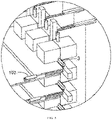
- the cable connection structure specifically includes the bearing member 101, the at least one cable connector 104 fixedly provided on the bearing member 101, and the sliding structure 102 connected to the bearing member 101.
- the cable connector 104 is fixed to the bearing member 101.
- the cable connector 104 can be fixed to the bearing member 101 by crimping (of course, except for a fixing role, crimp pins do not have a signal transmission function).
- the cable connector 104 can also be fixed to the bearing member 101 by other means (such as welding, bonding, or clamping).
- the cable connector 104 has the first port and the second port, the first port is configured to connect to the cable 12, and the second port can be electrically connected to the first port while connected to the other ports.
- the signal can be transmitted through the cable 12 to the first port connected to the cable 12 and then to other ports connected to the second port in connection with the first port.
- the sliding structure 102 connected to the bearing member 101 can specifically be a slide rail.
- the bearing member 101 can be connected to the single board 11 by the sliding structure 102, and the single board 11 connected to the bearing member 101 can slide in the first direction by means of the sliding structure 102.
- the first direction is a direction close to or away from the second port of the cable connector 104.
- the sliding is relative. If the single board 11 connected to the sliding structure 102 is fixed and cannot slide, the bearing member 101 can slide in the first direction relative to the single board 11.
- the cable connection structure allows the position of the cable connector 104 to change in a certain direction relative to the single board 11 by fixing the cable connector 104 to the bearer member 101 that is slidable relatively to the single board 11.
- the sliding structure 102 can change the position of the cable connector 104 relative to the single board 11, so that the cable connector 104 is still positioned in the full-mate state to ensure that the cable connector 104 can work in the full-mate state.
- This approach avoids the degradation of the connector performance that may affect the transmission of signals when the deformation or tolerance of the single board 11 accumulates at the connector to make the connector work in the de-mate state.
- the bearing member 101 is in the form of a plate with a plurality of cable connectors 104, and the plurality of cable connectors 104 are arranaged sequentially along a direction perpendicular to the first direction.
- the bearer member 101 of the cable connection structure can be specifically in the form of a plate.
- the bearing member can be a single board 11 having a size smaller than a general single board 11.
- a plurality of cable connectors 104 are fixed to the bearing member 101 and arranged along the direction perpendicular to the first direction, that is, the cable connectors 104 are arranged perpendicularly to the direction in which the single board 11 slides.
- the cable connectors 104 arranged in the direction perpendicular to the first direction can ensure that the length of the bearing member 101 in the direction perpendicular to the first direction is fully utilized (if the cable connectors 104 are arranged in a direction parallel to the first direction, for a length of the bearing member 101 in the direction perpendicular to the first direction, only a length of a single cable connector 104 is utilized), thereby reducing the size of the bearing member 101.
- the cable connection structure further includes a sliding lock 103 configured to fix the sliding structure 102 relative to the bearing member 101.
- the cable connection structure further includes a sliding lock 103 by which the sliding structure 102 can be fixed in place relative to the bearing member 101.
- the sliding lock allows for a rigid structural relationship between the single board 11 connected to the sliding structure 102 and the bearing member 101 in a fixed relative position.
- the single board 11 connected to the sliding structure 102 when the sliding lock 103 is locked, the single board 11 connected to the sliding structure 102 is fixed and cannot slide, and the bearing member 101 is also fixed and cannot slide; when the sliding lock 103 is unlocked, the single board 11 connected to the sliding structure 102 can slide relative to the bearing member 101 (the single board 11 connected to the sliding structure 102 is slidable along the sliding structure 102 or the bearing member 101 is slidable along the sliding structure 102 or both the single board 11 and the bearing member 101 are slidable along the sliding structure 102).
- the sliding lock 103 can be used to fix the relative position between the single board 11 connected to the sliding structure 102 and the bearing member 101, thereby facilitating their installation or movement as a whole.
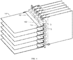
- an embodiment of the disclosure provides a single-board assembly 1, the single-board assembly comprising: a single board 11 and any one of the above cable connection structures, wherein the single board 11 is slidably connected to the bearing member 101 through the sliding structure 102.
- the single board 11 includes at least one cable interface 111.
- the single-board assembly 1 further includes a cable 12 connected between the cable interface 111 and a first port of a cable connector 104.
- the single-board assembly 1 specifically includes any one of the above cable connection structures, and the single board 11 slidably connected to the bearing member 101 of the cable connection structure by the sliding structure 102 of the cable connection structure.
- the single board 11 is provided with at least one cable interface 111 (which, in particular, may also be the cable connector).
- the cable interface 111 can be located anywhere on the single board 11 (e.g., on the board or on the edge of the board).
- the cable interface 111 on the single board 11 is connected to the first port of the cable connector 104 of the cable connection structure via the cable 12.
- the single board 11 may be a service board, or a switching network board, for example.
- the cable interface 111 on the single board 11 and the cable connector 104 of the cable connection structure may have a one-to-one relationship, i.e., each cable interface 111 on the single board 11 is connected to a first port of a different cable connector 104 of the cable connection structure.
- the cable interface 111 on the single board 11 and the cable connector 104 of the cable connection structure may have a one-to-many relationship, i.e., each cable interface 111 on the single board 11 is connected to first ports of a plurality of different cable connectors 104 of the cable connection structure.
- the cable interface 111 on the single board 11 and the cable connector 104 of the cable connection structure may have a many-to-one relationship, i.e., a first port of each cable connector 104 of the cable connection structure is connected to a plurality of different cable interfaces 111 on the single board 11.
- the cable 12 has flexibility compared to the PCB.
- the cable connector 104 is connected to the single board 11 via the cable 12. Even though the relative position of the cable connector 104 to the single board 11 changes, the signal transmission will not be affected due to their connection through the cable 12.
- the single-board assembly 1 allows, by means of the flexibility of the cable 12, the position of the cable connector 104 to change in a certain direction relative to the single board 11 by fixing the cable connector 104 to the bearer member 101 that is slidable relatively to the single board 11.
- the sliding structure 102 can change the position of the cable connector 104 relative to the single board 11, so that the cable connector 104 is still positioned in the full-mate state to ensure that the cable connector 104 can work in the full-mate state.
- This approach avoids the degradation of the connector performance that may affect the transmission of signals when the deformation or tolerance of the single board 11 accumulates at the connector to make the connector work in the de-mate state.
- an embodiment of the disclosure provides a single-board assembly connection structure, the single-board assembly connection structure including:
- each single-board assembly 2 includes a bearing member 201, a sliding structure 202, and a cable connector 204 disposed on the bearing member 201; in some embodiments, the single-board assembly 2 also includes a sliding locking structure 203.
- the single-board assembly 2 and the single-board assembly 1 can have essentially the same structure, which is the single-board assembly according to the embidment of the disclosure.
- the single-board assembly connection structure particularly includes the first single-board assembly group and the second single-board assembly group.
- Each of the single-board assembly groups includes the at least one single-board assembly 1 or 2.
- Each single-board assembly 1 of the first single-board assembly group has a second port of at least one cable connector 104 electrically connected to a second port of a cable connector 204 of one of the single board assemblies 2 of the second single-board assembly group.
- the single-board assembly connection structure allows the position of the cable connector 104 to change in a certain direction relative to the single board 11 by fixing the cable connector 104 to the bearer member 101 that is slidable relatively to the single board 11.
- the sliding structure 102 can change the position of the cable connector 104 relative to the single board 11, so that the cable connector 104 is still positioned in the full-mate state to ensure that the cable connector 104 can work in the full-mate state.
- This approach avoids the degradation of the connector performance that may affect the transmission of signals when the deformation or tolerance of the single board 11 accumulates at the connector to make the connector work in the de-mate state.
- a second port of at least one cable connector 104 in each single-board assembly 1 of the first single-board assembly group is connected to a second port of cable connector 204 of a single-board assembly 2 of the second single-board assembly group.
- each single-board assembly 1 of the first single-board assembly group has a second port of at least one cable connector 104 connected to a second port of the cable connector 204 of one of the single board assemblies 2 of the second single-board assembly group.
- the term "connected” refers to the connection of the cable connectors 104 or 204 of the different groups in the full-mate state.
- the second port of at least one cable connector 104 of each single-board assembly 1 in the first single-board assembly group is directly connected to the second port of the cable connector 204 of one of the single board assemblies 2 in the second single-board assembly group, rather than being electrically connected via other ports or cables 12, for example.
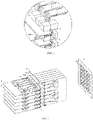
- the first single-board assembly group includes any of the above single board assemblies 1, wherein the single boards 11 of each single-board assembly 1 are parallel to each other; and the second single-board assembly group includes any of the above single board assemblies 2, wherein the single boards 21 of each single-board assembly 2 are parallel to each other and have an included angle larger than 0 degrees and less than or equal to 90 degrees with respect to the single boards 11 in the first single-board assembly group.
- the first single-board assembly group includes a plurality of single board assemblies 1
- the second single-board assembly group includes a plurality of single board assemblies 2.
- the single board 11 or 21 in the first single-board assembly group and the second single-board assembly group can be a service single board or a switching network board, for example, which is usually in the form of a plate.
- the single boards 11 of each single-board assembly 1 of the first single-board assembly group are parallel to each other, and the single boards 21 of each single-board assembly 2 of the second single-board assembly group are parallel to each other.
- the single boards (i.e., the single board 11 and single board 21) of the single board assemblies of different groups are arranged at a specific included angle (i.e., inclined relative to each other).
- the single boards of the single board assemblies of different groups are inclined relative to each other, and the single boards of each single-board assembly can intersect with the single boards of the single board assemblies in another single-board assembly group for more connections.
- an included angle between the single board 11 and the single board 21 is greater than 60 degrees and less than or equal to 90 degrees. Further more, as shown in FIG. 2 , the included angle between the single board 21 and the single board 11 is equal to 90 degrees, such that the first single-board assembly group and the second single-board assembly group form an orthogonal high-speed system architecture.
- the first single-board assembly group and the second single-board assembly group it is possible to achieve the connection of the cable interface 111 on the single board 11 of the first single-board assembly group to the first port of the cable connector 104 of the cable connection structure in the single-board assembly 1 of the first single-board assembly group via the cable 12, the connection of the second port of the cable connector 104 in the first single-board assembly group to the second port of the cable connector 204 in the second single-board assembly group, and the connection of the first port of the cable connector 204 in the second single-board assembly group to the cable interface 211 on the single board 21 of the second single-board assembly group via the cable 22.
- the transmission of signals from the single board 11 of the first single-board assembly group to the single board 21 of the second single-board assembly group can be achieved.
- the signal can also be transmitted in reverse, i.e., from the single board 21 of the second single-board assembly group to the single board 11 of the first single-board assembly group.
- the single-board assembly connection structure further includes a connection lock 3 configured to lock the cable connector 104 of the first single-board assembly group to the cable connector 204 of the second single-board assembly 2 that is electrically connected to the cable connector 104.
- the single-board assembly connection structure further includes a connection lock 3 configured to lock the cable connector 104 of the first single-board assembly group to the cable connector 204 of the second single-board assembly group.
- the connection lock 3 is locked to secure the cable connector 104 of the first single-board assembly group to the cable connector 204 of the second single-board assembly group.
- the cable connector 104 of the first single-board assembly group and the cable connector 204 of the second single-board assembly group are always fully mated to ensure that the cable connector 104 of the first single-board assembly group and the cable connector 204 of the second single-board assembly group can work in the full-mate state.
- the single-board assembly connection structure further includes a retaining frame 5, the first single-board assembly group and the second single-board assembly group being arranged on opposite sides of the retaining frame 5.
- the single-board assembly connection structure further includes: a retaining frame 5, which can be specifically a system frame, on opposite sides of which the first single-board assembly group and the second single-board assembly group are located, respectively.
- the retaining frame 5 has a slot for insertion of the single board 11 or the single board 21. When the single board 11 or single board 21 is fully inserted into the slot, it is assumed that the cable connector 104 or cable connector 204 corresponding to the single board 11 or single board 21 is seated in place.
- the single-board assembly 1 or 2 of the single-board assembly connection structure acconding to this embodiment of the disclosure both include a sliding lock, an assembly process of which can specifically be as follows.
- the bearing member 101 or 201 of the cable connection structure and the single board 11 or 21 of the single-board assembly 1 or 2 become a rigid structural relationship, and have a fixed relative position.
- the single board 11 or 21 of the single-board assembly 1 or 2 having the fixed relative position to the bearing member 101 or 102 is inserted into the retaining frame 5, such that the second port of the cable connector 104 or 204 thereon can be connected to the second port of the cable connector 204 or 104 of the single-board assembly 2 or 1 in the corresponding group.
- the connection lock 3 is locked to fix the connection status of the cable connector 104 of the first single-board assembly group and the cable connector 204 of the second single-board assembly group.
- the sliding locks 103 and 203 are also unlocked to allow the single boards 11 and 12 to slide along the sliding structures 102 and 202.
- the single board 11 or 21 is slid to reach its predetermined position (i.e., the position of the cable connector 104 or 204 does not move and the single board 11 or 21 can be slidable without being fully inserted into the fixed frame 5) to ensure that the system of the single-board assembly connection structure can work properly.
- the cable connector 104 of the first single-board assembly group and the cable connector 204 of the second single-board assembly group can also work in the full-mate state.
- the cable connection structure of the single-board assembly connection structure further includes a sliding lock 103 or 203.
- the single-board assembly connection structure further includes a linkage structure 4 that is configured to place the connection lock 3 in a locked state and place the sliding lock in an unlocked state; or to place the connection lock 3 in an unlocked state and place the sliding lock in a locked state.
- the single-board assembly connection structure further includes a sliding lock 103 or 203, a connection lock 3, and a linkage structure 4.
- the single board 11 or 21 of the single-board assembly 1 or 2 reaches a rigid structural relationship with the bearing member 101 or 201 and has a fixed relative position.
- the sliding lock 103 or 203 of the single-board assembly 1 or 2 is in the unlocked state, the single board 11 or 12 of the single-board assembly 1 or 2 is slidable in the first direction relative to the bearing member 101 or 201.
- connection lock 3 When the connection lock 3 is in the locked state, the second port of the cable connector 104 of the first single-board assembly group is connected to the second port of the cable connector 204 of the second single-board assembly group, i.e., the cable connector 104 of the first single-board assembly group is fully mated with the cable connector 204 of the second single-board assembly group.
- the connection lock 3 When the connection lock 3 is unlocked, the position of the second port of the cable connector 104 of the first single-board assembly group and the position of the second port of the cable connector 204 of the second single-board assembly group can be changed relative to each other.
- the linkage structure 4 links the sliding lock 103 or 203 and the connection lock 3 to ensure that when the connection lock 3 is in the locked state, the sliding lock is in the unlocked state; or when the connection lock 3 is in the unlocked state, the sliding lock is in the locked state.
- the linkage structure 4 enables the linkage of the connection lock 3 and the sliding lock 103 or 203, thereby avoiding the connection lock 3 and the sliding lock 103 or 203 being in the same state to result in an inproper work of the single-board assembly connection structure according to the embodiment of the disclosure. If both the connection lock 3 and the sliding lock 103 or 203 are in the unlocked state, the bearing member 101 or 201 can also slide as the single board 11 or 21 slides, causing that the cable connector 104 of the first single-board assembly group and the cable connector 204 of the second single-board assembly group can not fully mated with each other.
- connection lock 3 in a locked state and place the sliding lock in an unlocked state; or place the connection lock 3 in an unlocked state and place the sliding lock in a locked state, by manual control.
- the board assembly connection structure further includes a back plate 6.
- the bearing member 101 or 201 is coupled to the back plate 6.
- the back plate 6 has a third port, the third port is connected to a second port, and the third port which is connected to the second port of the single-board assembly 1 in the first single-board assembly group is connected via a connection circuit to another third port which is connected to the second port of the single-board assembly 2 in the second single-board assembly group.
- the bearing member 101 or 201 is connected to the back plate 6, and the second port of the cable connector 104 of each single-board assembly 1 in the first single-board assembly group can also be connected to a port of the back plate connector on the back plate 6, i.e., the second port of the cable connector 104 is fully mated with the back plate connector.
- the second port of the cable connector 204 of each single-board assembly 2 in the second single-board assembly group is also connected to another port of the back plate connector, also in the full-mate state.
- the back plate 6 has a plurality of back plate connectors 601.
- the cable connectors 104 in the first single-board assembly group that connect different ports of the same back plate connector are electrically connected to the cable connectors 204 in the second single-board assembly group via the back plate connectors 601. Since the cable connectors 104 or 204 of each single-board assembly 1 or 2 are in the full-mate state with the back plate connectors 601, the cable connectors 104 in the first single-board assembly group are naturally and fully mated with the cable connectors 204 in the second single-board assembly group.
- the first single-board assembly group and the second single-board assembly group can be arranged on the same side of the back plate 6.
- the different back plate connectors on the back plate 6 are electrically connected.
- the cable connector 104 in the first single-board assembly group and the cable connector 204 in the second single-board assembly group that connects the two electrically connected back plate connectors are also connected through the two back plate connectors.
- the second single-board assembly group can also be replaced with a conventional PCB crimp connector.
- the second port of the cable connector 104 of the single-board assembly 1 in the first single-board assembly group is connected to the PCB crimp connector through the back plate connector for implementing the signal transmission.
Landscapes
- Engineering & Computer Science (AREA)
- Microelectronics & Electronic Packaging (AREA)
- Details Of Connecting Devices For Male And Female Coupling (AREA)
Applications Claiming Priority (2)
| Application Number | Priority Date | Filing Date | Title |
|---|---|---|---|
| CN202010897474.6A CN114126311B (zh) | 2020-08-31 | 2020-08-31 | 线缆连接结构、单板组件、单板组件连接结构 |
| PCT/CN2021/113543 WO2022042420A1 (zh) | 2020-08-31 | 2021-08-19 | 线缆连接结构、单板组件、单板组件连接结构 |
Publications (2)
| Publication Number | Publication Date |
|---|---|
| EP4040929A1 true EP4040929A1 (de) | 2022-08-10 |
| EP4040929A4 EP4040929A4 (de) | 2023-11-08 |
Family
ID=80352630
Family Applications (1)
| Application Number | Title | Priority Date | Filing Date |
|---|---|---|---|
| EP21860258.9A Pending EP4040929A4 (de) | 2020-08-31 | 2021-08-19 | Kabelverbindungsstruktur, einzelplatinenanordnung und verbindungsstruktur für einzelplatinenanordnung |
Country Status (4)
| Country | Link |
|---|---|
| US (1) | US12016146B2 (de) |
| EP (1) | EP4040929A4 (de) |
| CN (1) | CN114126311B (de) |
| WO (1) | WO2022042420A1 (de) |
Families Citing this family (3)
| Publication number | Priority date | Publication date | Assignee | Title |
|---|---|---|---|---|
| CN113745868B (zh) * | 2020-05-30 | 2023-09-12 | 华为技术有限公司 | 一种板级架构及通信设备 |
| CN118841768A (zh) * | 2023-04-24 | 2024-10-25 | 华为技术有限公司 | 一种连接器、电路板组件和电子设备 |
| CN119315303A (zh) * | 2023-07-11 | 2025-01-14 | 华为技术有限公司 | 一种电子设备 |
Family Cites Families (27)
| Publication number | Priority date | Publication date | Assignee | Title |
|---|---|---|---|---|
| US5211565A (en) * | 1990-11-27 | 1993-05-18 | Cray Research, Inc. | High density interconnect apparatus |
| US6843657B2 (en) * | 2001-01-12 | 2005-01-18 | Litton Systems Inc. | High speed, high density interconnect system for differential and single-ended transmission applications |
| US7210586B2 (en) * | 2002-08-13 | 2007-05-01 | Finisar Corporation | Adapter element for card cage system |
| US7331717B2 (en) * | 2004-07-01 | 2008-02-19 | Amphenol Corporation | Flexible optical interconnection system |
| JP4531668B2 (ja) * | 2005-09-16 | 2010-08-25 | 株式会社日立国際電気 | 電子装置 |
| US7850260B2 (en) * | 2007-06-22 | 2010-12-14 | Oracle America, Inc. | Injection/ejection mechanism |
| US8064200B1 (en) * | 2008-04-16 | 2011-11-22 | Cyan Optics, Inc. | Cooling a chassis by moving air through a midplane between two sets of channels oriented laterally relative to one another |
| US7885066B2 (en) * | 2008-07-17 | 2011-02-08 | Juniper Networks, Inc. | Airflow/cooling solution for chassis with orthogonal boards |
| US7690927B1 (en) * | 2009-03-19 | 2010-04-06 | International Business Machines Corporation | Processor scaling across multiple computer blades |
| GB0917498D0 (en) * | 2009-10-07 | 2009-11-18 | 3M Innovative Properties Co | Connector module for telecommunication patch panels |
| WO2012106510A2 (en) * | 2011-02-02 | 2012-08-09 | Corning Cable Systems Llc | Dense fiber optic connector assemblies and related connectors and cables suitable for establishing optical connections for optical backplanes in equipment racks |
| CN102695393B (zh) * | 2012-05-04 | 2014-11-05 | 华为技术有限公司 | 一种垂直正交互连系统及通信设备 |
| US9148975B2 (en) * | 2012-06-22 | 2015-09-29 | Advanced Micro Devices, Inc. | Electronic interconnect method and apparatus |
| CN103974538B (zh) * | 2013-02-05 | 2017-09-12 | 华为技术有限公司 | 电子设备、电子系统及其电路板互联架构 |
| US20140273551A1 (en) * | 2013-03-14 | 2014-09-18 | Molex Incorporated | Cable module connector assembly suitable for use in blind-mate applications |
| CN103718658A (zh) * | 2013-03-18 | 2014-04-09 | 华为技术有限公司 | 背板、插框和网络设备 |
| CN104254199B (zh) * | 2013-06-27 | 2018-07-31 | 华为技术有限公司 | 电子板卡系统及电子设备 |
| CN103545630B (zh) * | 2013-10-30 | 2016-06-22 | 华为技术有限公司 | 一种板间连接装置 |
| US9591781B2 (en) * | 2013-12-13 | 2017-03-07 | Brocade Communications Systems, Inc. | Floating daughter card system |
| CN106951036B (zh) * | 2016-01-07 | 2020-09-01 | 纬创资通(中山)有限公司 | 电子模块及电子设备 |
| CN106654728B (zh) * | 2016-11-14 | 2019-02-05 | 华为技术有限公司 | 一种连接器及通信设备 |
| US10028403B1 (en) * | 2017-05-11 | 2018-07-17 | Dell Products L.P. | Floating circuit board connector system |
| CN107239427B (zh) * | 2017-06-09 | 2020-12-01 | 华为技术有限公司 | 连接装置、网板连接系统和通信设备 |
| CN107719331B (zh) * | 2017-11-02 | 2021-05-25 | 蔚来(安徽)控股有限公司 | 浮动对接装置、换电机器人、对接方法和复位方法 |
| CN209627835U (zh) * | 2019-01-07 | 2019-11-12 | 烽火通信科技股份有限公司 | 一种信号板、插框系统及网络设备 |
| CN110635274B (zh) * | 2019-08-26 | 2021-04-09 | 华为技术有限公司 | 一种线路板组件、背板互连系统及电子设备 |
| CN111413522B (zh) * | 2020-03-03 | 2023-02-28 | 武汉精鸿电子技术有限公司 | 一种用于连接器插拔的治具及包含其的测试设备 |
-
2020
- 2020-08-31 CN CN202010897474.6A patent/CN114126311B/zh active Active
-
2021
- 2021-08-19 WO PCT/CN2021/113543 patent/WO2022042420A1/zh not_active Ceased
- 2021-08-19 US US17/773,689 patent/US12016146B2/en active Active
- 2021-08-19 EP EP21860258.9A patent/EP4040929A4/de active Pending
Also Published As
| Publication number | Publication date |
|---|---|
| CN114126311B (zh) | 2025-08-22 |
| US20220386494A1 (en) | 2022-12-01 |
| US12016146B2 (en) | 2024-06-18 |
| EP4040929A4 (de) | 2023-11-08 |
| WO2022042420A1 (zh) | 2022-03-03 |
| CN114126311A (zh) | 2022-03-01 |
Similar Documents
| Publication | Publication Date | Title |
|---|---|---|
| US12016146B2 (en) | Cable connection structure, single-board assembly, single-board assembly connection structure | |
| US20250062573A1 (en) | Electrical connector system | |
| US11695227B2 (en) | Connector with tolerance module | |
| KR101854309B1 (ko) | Mimo 안테나 어셈블리 | |
| CN101882955B (zh) | 光背板互连系统及通信设备 | |
| EP3387711B1 (de) | Koaxialsteckverbinderanordnung und kommunikationssystem mit einer vielzahl von koaxialkontakten | |
| US7740489B2 (en) | Connector assembly having a compressive coupling member | |
| US20230155287A1 (en) | Phase shifter, remote electrical tilt system and base station antenna | |
| US9017087B1 (en) | Cable connector assembly and cable tray having a floatable cable connector | |
| EP2244191A1 (de) | PCI-E-Signalübertragungsvorrichtung und Bilderzeugungsvorrichtung damit | |
| US20190081376A1 (en) | Connector for waveguide, communication module, transmission cable, and electronic device | |
| US20140011396A1 (en) | Connector assembly having a floatable module assembly with a coupling member | |
| US20240260218A1 (en) | Orthogonal system architecture and network device | |
| US8641292B2 (en) | Photonic assembly for optical fibers | |
| EP2451022A1 (de) | Anschlussanordnungen mit Koppelseiten, die von fluidischen Kopplungsmechanismen verschoben werden | |
| CN114828604B (zh) | 一种具有模块化电磁信号屏蔽壳体的射频接受组件 | |
| US11923638B2 (en) | Circuit board assembly for a communication system | |
| EP3627629B1 (de) | Verbindungsvorrichtung, netzwerkplatinenverbindungssystem und kommunikationsvorrichtung | |
| CN112701502A (zh) | 一种浮动式板对板连接器 | |
| US12489232B2 (en) | Right angled blind mate interconnection | |
| CN108346856B (zh) | 天线装置 | |
| CN116931672A (zh) | 转接单元、转接模组及电子设备 | |
| US9653861B2 (en) | Interconnection of hardware components | |
| JP3250840U (ja) | コネクタ | |
| US20260074473A1 (en) | Rf multi connector unit for antennas, antenna system and base station |
Legal Events
| Date | Code | Title | Description |
|---|---|---|---|
| STAA | Information on the status of an ep patent application or granted ep patent |
Free format text: STATUS: THE INTERNATIONAL PUBLICATION HAS BEEN MADE |
|
| PUAI | Public reference made under article 153(3) epc to a published international application that has entered the european phase |
Free format text: ORIGINAL CODE: 0009012 |
|
| STAA | Information on the status of an ep patent application or granted ep patent |
Free format text: STATUS: REQUEST FOR EXAMINATION WAS MADE |
|
| 17P | Request for examination filed |
Effective date: 20220504 |
|
| AK | Designated contracting states |
Kind code of ref document: A1 Designated state(s): AL AT BE BG CH CY CZ DE DK EE ES FI FR GB GR HR HU IE IS IT LI LT LU LV MC MK MT NL NO PL PT RO RS SE SI SK SM TR |
|
| A4 | Supplementary search report drawn up and despatched |
Effective date: 20231009 |
|
| RIC1 | Information provided on ipc code assigned before grant |
Ipc: H01R 12/70 20110101ALN20231002BHEP Ipc: H05K 7/14 20060101AFI20231002BHEP |
|
| DAV | Request for validation of the european patent (deleted) | ||
| DAX | Request for extension of the european patent (deleted) | ||
| GRAP | Despatch of communication of intention to grant a patent |
Free format text: ORIGINAL CODE: EPIDOSNIGR1 |
|
| STAA | Information on the status of an ep patent application or granted ep patent |
Free format text: STATUS: GRANT OF PATENT IS INTENDED |
|
| RIC1 | Information provided on ipc code assigned before grant |
Ipc: H05K 7/14 20060101AFI20260206BHEP Ipc: H01R 12/70 20110101ALN20260206BHEP |
|
| GRAS | Grant fee paid |
Free format text: ORIGINAL CODE: EPIDOSNIGR3 |
|
| INTG | Intention to grant announced |
Effective date: 20260313 |
|
| GRAA | (expected) grant |
Free format text: ORIGINAL CODE: 0009210 |
|
| STAA | Information on the status of an ep patent application or granted ep patent |
Free format text: STATUS: THE PATENT HAS BEEN GRANTED |