EP4041032B1 - Système de rangement de batterie de cuisine - Google Patents
Système de rangement de batterie de cuisine Download PDFInfo
- Publication number
- EP4041032B1 EP4041032B1 EP20873478.0A EP20873478A EP4041032B1 EP 4041032 B1 EP4041032 B1 EP 4041032B1 EP 20873478 A EP20873478 A EP 20873478A EP 4041032 B1 EP4041032 B1 EP 4041032B1
- Authority
- EP
- European Patent Office
- Prior art keywords
- bridge
- cookware
- wall
- storage system
- cookware storage
- Prior art date
- Legal status (The legal status is an assumption and is not a legal conclusion. Google has not performed a legal analysis and makes no representation as to the accuracy of the status listed.)
- Active
Links
Images

Classifications
-
- A—HUMAN NECESSITIES
- A47—FURNITURE; DOMESTIC ARTICLES OR APPLIANCES; COFFEE MILLS; SPICE MILLS; SUCTION CLEANERS IN GENERAL
- A47J—KITCHEN EQUIPMENT; COFFEE MILLS; SPICE MILLS; APPARATUS FOR MAKING BEVERAGES
- A47J47/00—Kitchen containers, stands or the like, not provided for in other groups of this subclass; Cutting-boards, e.g. for bread
- A47J47/16—Stands, or holders for kitchen articles
-
- A—HUMAN NECESSITIES
- A47—FURNITURE; DOMESTIC ARTICLES OR APPLIANCES; COFFEE MILLS; SPICE MILLS; SUCTION CLEANERS IN GENERAL
- A47B—TABLES; DESKS; OFFICE FURNITURE; CABINETS; DRAWERS; GENERAL DETAILS OF FURNITURE
- A47B81/00—Cabinets or racks specially adapted for other particular purposes, e.g. for storing guns or skis
- A47B81/04—Cabinets or racks specially adapted for other particular purposes, e.g. for storing guns or skis specially adapted for storing dishware
-
- A—HUMAN NECESSITIES
- A47—FURNITURE; DOMESTIC ARTICLES OR APPLIANCES; COFFEE MILLS; SPICE MILLS; SUCTION CLEANERS IN GENERAL
- A47B—TABLES; DESKS; OFFICE FURNITURE; CABINETS; DRAWERS; GENERAL DETAILS OF FURNITURE
- A47B65/00—Book-troughs; Accessories specially adapted for book-storing, e.g. book-ends
- A47B65/10—Book-troughs; Accessories specially adapted for book-storing, e.g. book-ends adjustable
-
- A—HUMAN NECESSITIES
- A47—FURNITURE; DOMESTIC ARTICLES OR APPLIANCES; COFFEE MILLS; SPICE MILLS; SUCTION CLEANERS IN GENERAL
- A47B—TABLES; DESKS; OFFICE FURNITURE; CABINETS; DRAWERS; GENERAL DETAILS OF FURNITURE
- A47B77/00—Kitchen cabinets
- A47B77/04—Provision for particular uses of compartments or other parts ; Compartments moving up and down, revolving parts
- A47B77/14—Provision for particular uses of compartments or other parts ; Compartments moving up and down, revolving parts by incorporation of racks or supports, other than shelves, for household utensils
Definitions
- Modem day kitchens often include numerous pots and pans (“cookware”) for cooking. Due to varied cooking needs, many kitchens include numerous size pots and pans, resulting in a need to store such cookware.
- US2005279725 discloses a storage and organization device for use in conjunction with kitchen items, including magnets for attaching the device to a metal surface, such as the side of a kitchen appliance.
- the system is modular, and provides a storage solution that is capable of holding significant weight with efficiency.
- the cookware system comprises a plurality of storage units configured to store pots and pans. Each cookware storage unit is configured for magnetic coupling with one or more additional cookware storage units.
- the storage unit includes a first wall, second wall, bridge and gap.
- the system provides a space-saving benefit. Further disclosed is a novel system and device that avoids the need for stackable solutions, which are inefficient, time consuming, and lead to frustration.
- the system provides an integrated drying system for drying cookware, as well as dinnerware, cutlery, gadgets and cooking utensils (the "components"), while also providing integrated storage.
- the cookware, dinnerware, cutlery, gadgets and utensils are stored in slots that provide convenient storage, while also providing circulation of air around the stored components, including underneath the components.
- the components are placed in slots, elevated above the floor, to allow for air circulation underneath. This eliminates the need for dedicated drying racks, hand drying, or use of the dishwasher.
- the cookware system incorporates modular storage units, without the need for stacking.
- a plurality such as, for example, four pan racks, are connected to one another.
- Each pan rack may be a slot, with each slot being optimized to store one cookware component (such as, for example, a pot).
- the racks are specially formulated such that they can be placed within kitchen cabinets or other storage spaces, or also sit out on counters or tables.
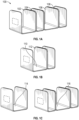
- FIGS. 1A-1C illustrated are various embodiments of the cookware storage system.
- FIG. 1A illustrates the system 100 with four slots 102, 104, 106, 108, each slot being connected to another, and forming one modular unit. However, each slot may also include its own floor 110 and sidewalls 112, as shown in FIG. 1B .
- system, slots and modular units may be any suitable shape or size, and those illustrated in the drawings are for illustrative purposes only.
- FIG. 1B illustrates a close-in view of the system illustrated in FIG. 1A .
- the slots may be formed in multiple widths, as shown.
- each slot is modular, and allows for separation and based on unique needs. Therefore, in certain embodiments, each slot may be completely separable from one another, and completely modular.
- FIG. 1C illustrates an exemplary view of the system, with a modular slot 114 removed from the remaining slots 116.
- the system may be separated into discrete slots.
- the slots may then be attached to one another to form a cohesive rack system.
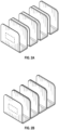
- FIGS. 2A and 2B illustrated are views of the system in various configurations.
- the system avoids the use of hook and loop fasteners (sold under the brand name VELCRO, for example), which would otherwise fall off or weaken over time. Further, the system avoids interconnected slots between the walls, which would not allow for use as standalone racks.
- VELCRO brand name
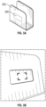
- the cookware storage system includes a magnetic attachment mechanism 300 within each sidewall of the slot 302. This feature is illustrated in FIG. 3 .
- the mechanism may be located on either sidewall of the individual rack.
- the magnetic attachment mechanism may include a door.
- the door may be flush with the sidewall.
- the door may be protruding from the sidewall, or may be further indented from the sidewall.
- the door may be formed of identical material to the sidewall, or of a different material, color, or texture. In another embodiment, the door may be formed of a specialized material, to allow the magnets residing underneath to maintain their strength.
- FIG. 3B illustrates a portion of the sidewall with a cover removed, showing a residing portion 301 for a magnet, in accordance with certain embodiments.
- ABS plastic Acrylonitrile Butadiene Styrene (ABS) plastic may be used for the door.
- An exemplary embodiment of the inner side 400 of the door is shown in FIG. 4 .
- one or more magnets may be used to form a magnetic connection with the adjacent rack.
- a single slot 402, or multiple slots 404 may be formed within the sidewall, underneath the door, corresponding to space for the required magnets. It should be noted, however, that additional quantities of magnets are contemplated by the invention.
- an ABS door cover may be used to cover the magnets forming the magnetic connection.
- the ABS door may be specifically formed to maintain proper shape, but also to allow for maximum magnetic strength.
- the door may have a thickness of 0.2 mm.
- a 30 x 19 x 1.6 mm magnet may be used.
- the magnet may have a strength of N54 or any suitable variation thereof.
- the N54-type magnet may provide sufficient force to maintain interconnection between a plurality of sidewalls, while allowing for easy detachment, and not interfering with the ability of the cookware itself to reside therein.
- This particularly sized magnet may be placed within the sidewall, such as shown in FIG. 3 .
- the magnet is optimally formed and sized to hold cookware racks in place relative and adjacent to one another, and allowing the racks to connect. It should be noted that the magnet may be of a similar size, such as between 25-35 x 15-23 x 1-2 mm.
- a space may be located within the rack, below the resting position of the cookware and above the floor/foundation.
- this space may be 0.6 meters (two feet) from top to bottom, or a variation thereof, such as approximately 0.6 meters (two feet).
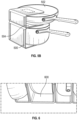
- FIGS. 5A-5B illustrated are various cookware elements 502 within the modular racks 500. Further illustrated are the spaces below the stored cookware, and above the floor 504, which allow for circulation of air, thereby providing a drying system to the cookware. FIG. 6 illustrates the space 500 for drying in further details.
- the storage system may be formed of a plastic, such as ABS plastic, or any other suitable material, such as fiberglass, composites, metal, or wood.
- the plastic is of any suitable width.
- the ABS plastic may be formed of a specific width that provides structural support to the cookware, without bending. Thus, 3 mm ABS plastic, which bent when the cookware was stacked, may not be used. In an embodiment, 5 mm ABS plastic may be used, due to its durability and strength.
- the ABS plastic may be ABS Texture G1001A, or a suitable replacement.
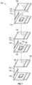
- the cookware storage system 700 may include three or more cookware storage units 702, 704, 706.
- Each storage unit may include a first wall 708, a second wall 710, a bridge 712, and a gap 714.
- the bridge may form a first juncture 716 with the first wall and a second juncture 718 with the second wall.
- the junctures connect the first and second wall to the bridge, preferably providing an angle between them of approximately 90 degrees.
- the junctures are strong enough to support the structural integrity of the bridge and walls, and should be able to hold pots or pans leaning against the first and second walls and prevent the walls from bending more than ninety-five (95) degrees from the bridge.
- the gap being formed by the first and second walls and the bridge, and in some embodiments, is large enough to receive and store pots and pans of varying dimensions. Accordingly, the gap may be open on at least three sides so that the cookware storage units can be made larger or wider than the pots and pans that they hold. It is expected that the pots and pans may extend out through the empty sides of the gap such that their center aligns with the center of the first and second walls.
- the bridge comprises a main body 720, as well as an embossed portion 722 which extends from the main body.
- the embossed portion may elevate the main body by 5mm or more, but should extend at least 2mm.
- the embossed portion may feature a high-friction surface in order to prevent the storage units from sliding about on a kitchen counter or inside a kitchen cabinet.
- the embossed portion does not need to be particularly wide, and may comprise less than 10%, or even less than 5% of the surface area of the main body.
- Each wall includes an inward face 740 and an outward face 742, with an inner compartment 744 embedded between the faces.
- the inner compartment may be sufficiently deep to accommodate one or magnets 746 of sufficient strength to couple the storage units.
- the storage units may also be designed so that the magnets couple based on their respective polarities. That is, just as the magnets have north and south poles, with the north attracting the south and vice versa, so too should the storage units have north and south poles corresponding to the magnets embedded in the inner compartments of the walls.
- the inner walls may have doors 748 to facilitate the removal and replacement of magnets that have lost their polarity.
- pots and pans are frequently made of magnetic material, at least to facilitate their use on induction-based stove tops, it is helpful to block or limit the magnetic fields effect on the pots and pans placed in the storage units. Otherwise, there is the risk that by picking up a single magnetic pot, the entire stack of storage units might also be lifted. At the same time, it may helpful for some level of magnetic coupling between the pots and the pans and the storage units in order to decrease the incidence of the pots and pans sliding out of the storage units, and to maintain the stability of the cookware storage ecosystem as a whole. These goals may be accomplished by the allocative application of ferromagnetic material on the inner faces of the walls.
- the bridge itself may be designed to be extended via the coupling of an inner and outer sleeve 752, 754.
- the outer dimensions of the inner sleeve may roughly correspond to the inner dimensions of the outer sleeve, so that the inner sleeve may be slidably disposed inside the outer sleeve.
- the walls may also be designed for extension to correspond to the varying diameters of the pots and pans with inner and outer sleeves 756, 758.
- An exemplary embodiment of the cookware storage system includes a plurality of cookware storage units configured to store pots and pans. Each cookware storage unit being configured for magnetic coupling with at least one or more additional cookware storage units. Each cookware storage unit includes a first wall, a second wall, a bridge, and a gap. The bridge forms a first juncture with the first wall and a second juncture with the second wall. The bridge is configured to rest against a hard surface and include a main body and an embossed portion.
- the embossed portion extends at least 2mm from the main body.
- the embossed portion comprises a certain percentage of a surface area of the main body, such as less than 10%.
- the embossed portion provides at least 2mm of distance between the main body and the hard surface.
- the first juncture connecting the bridge to the first wall and the second juncture connecting the bridge to the second wall does so at an angle between 85 and 95 degrees so that the bridge is substantially orthogonal to the first and second walls.
- the gap being a rectangular cuboid in shape, having six sides, formed on three sides by the first wall, the second wall, and the bridge, and being open to the atmosphere on three remaining sides to facilitate air drying of pots and pans.
- the first and the second wall each include an inward face and an outward face and at least one inner compartment.
- the inward face being oriented toward the gap, with the outward face being disposed opposite the inward face.
- the inner compartment being disposed between the inward face and the outward face.
- the inner compartment housing at least one magnet, the at least one magnet having a first pole, a second pole, and a magnetic field.
- the inward face being formed of a ferromagnetic material and configured to restrict the magnetic field of at least one magnet from entering the gap.
- the outward face being formed of a non-ferromagnetic material and configured to permit the magnetic field to transcend the outward face.
- the magnet in the inner compartment of the first wall being oriented so that the first pole is directed toward the gap and the magnet in the inner compartment of the second wall oriented so that the second pole is directed toward the gap.
- the bridge may include an inner sleeve and an outer sleeve, with the inner sleeve being disposed inside the outer sleeve.
- the inner sleeve and outer sleeve may extendedly engage such that the bridge can increase or decrease in length in order to accommodate pots or pans of varying height.
- the first and second walls each comprising an inner sleeve and an outer sleeve, with the inner sleeve being disposed inside the outer sleeve.
- the inner sleeve and outer sleeve may be extendedly engaged such that the first and second walls can increase or decrease in length in order to accommodate pots or pans of varying width.
- Each of the first and second walls may be at least ten centimeters (four inches) in width and ten centimeters (four inches) in length and configured to accommodate pots or pans having a diameter of more than fifteen centimeters (six inches).
- Each of the plurality of cookware storage units may include a door that is slidably or hingedly attached to the first and second walls to provide access to at least one inner compartment.
- the bridge may be between 2.5 and 23 centimeters (one to nine inches) in height.
Landscapes
- Engineering & Computer Science (AREA)
- Food Science & Technology (AREA)
- Cookers (AREA)
Claims (8)
- Système de stockage de batterie de cuisine (700) comprenant une pluralité d'unités de stockage de batterie de cuisine (702, 704, 706) configurées pour stocker des casseroles et des poêles, chaque unité de stockage de batterie de cuisine (702, 704, 706) étant configurée pour être couplée magnétiquement à deux autres unités de stockage de batterie de cuisine (702, 704, 706), chaque unité de stockage de batterie de cuisine (702, 704, 706) comprenant :une première paroi (708), une deuxième paroi (710), un pont (712) et un espace (714),le pont (712) formant une première jonction (716) avec la première paroi (708) et une deuxième jonction (718) avec la deuxième paroi (710) ;le pont (712) étant configuré pour reposer contre une surface dure et ayant un corps principal (720) et une partie en relief (722), la partie en relief (722) s'étendant d'au moins 2 mm à partir du corps principal (720), comprenant moins de 10 % d'une surface du corps principal (20) et étant configurée pour fournir au moins 2 mm de distance entre le corps principal (720) et la surface dure ;la première jonction (716) reliant le pont (712) à la première paroi (708) et la deuxième jonction (718) reliant le pont (712) à la deuxième paroi (710) toutes deux à un angle compris entre 85 et 95 degrés de sorte que le pont (712) soit sensiblement orthogonal aux première (708) et deuxième (710) parois ;l'espace (714) ayant une forme cuboïde rectangulaire, ayant six côtés, formés sur trois côtés par la première paroi (708), la deuxième paroi (710) et le pont (712), et étant ouvert à l'atmosphère sur les trois côtés restants pour faciliter le séchage à l'air des casseroles et des poêles ;les première (708) et deuxième (710) parois comprenant chacune une face intérieure (740) et une face extérieure (742) et au moins un compartiment interne (744),la face intérieure (740) étant orientée vers l'espace (714), la face extérieure (741) étant disposée à l'opposé de la face intérieure (740), l'au moins un compartiment interne (744) étant disposé entre la face intérieure (740) et la face extérieure (742) et logeant au moins un aimant (746), l'au moins un aimant (746) ayant un premier pôle, un deuxième pôle et un champ magnétique ;la face intérieure (740) étant constituée d'un matériau ferromagnétique et configurée pour restreindre l'entrée du champ magnétique de l'au moins un aimant (746) dans l'espace ;la face extérieure (742) étant constituée d'un matériau non ferromagnétique et configurée pour permettre au champ magnétique de dépasser la face extérieure (742) ;l'aimant (746) dans le compartiment interne (744) de la première paroi (708) étant orienté de sorte que le premier pôle soit dirigé vers l'espace (714) et l'aimant (746) dans le compartiment interne (744) de la deuxième paroi (710) étant orienté de sorte que le deuxième pôle soit dirigé vers l'espace (714).
- Système de stockage de batterie de cuisine selon la revendication 1, le pont comprenant un manchon interne et un manchon externe, le manchon interne étant disposé à l'intérieur du manchon externe, le manchon interne et le manchon externe étant mis en prise de manière étendue de sorte que la longueur du pont puisse augmenter ou diminuer afin d'accueillir des casseroles ou des poêles de hauteur variable.
- Système de stockage de batterie de cuisine selon la revendication 1, les première et deuxième parois comprenant chacune un manchon interne et un manchon externe, le manchon interne étant disposé à l'intérieur du manchon externe, le manchon interne et le manchon externe étant mis en prise de manière étendue de sorte que la longueur des première et deuxième parois puisse augmenter ou diminuer afin d'accueillir des casseroles ou des poêles de largeur variable.
- Système de stockage de batterie de cuisine selon la revendication 1, chacune de la pluralité d'unités de stockage de batterie de cuisine comprenant une porte, la porte étant fixée de manière coulissante ou articulée aux première et deuxième parois pour permettre l'accès à l'au moins un compartiment interne.
- Système de stockage de batterie de cuisine selon la revendication 1, les première et deuxième parois mesurant chacune au moins dix centimètres (quatre pouces) de large et dix centimètres (quatre pouces) de long et étant configurées pour accueillir des casseroles ou des poêles ayant un diamètre supérieur à quinze centimètres (six pouces).
- Système de stockage de batterie de cuisine selon la revendication 1, le pont mesurant entre 2,5 et 7,6 centimètres (un et trois pouces) de haut et étant configuré pour accueillir des poêles.
- Système de stockage de batterie de cuisine selon la revendication 1, le pont mesurant entre 7,6 et 15 centimètres (trois et six pouces) de haut et étant configuré pour accueillir des casseroles.
- Système de stockage de batterie de cuisine selon la revendication 1, le pont mesurant entre 15 et 23 centimètres (six et neuf pouces) de haut et étant configuré pour accueillir des casseroles.
Applications Claiming Priority (2)
| Application Number | Priority Date | Filing Date | Title |
|---|---|---|---|
| US201962911929P | 2019-10-07 | 2019-10-07 | |
| PCT/US2020/054366 WO2021071817A1 (fr) | 2019-10-07 | 2020-10-06 | Système de rangement de batterie de cuisine |
Publications (3)
| Publication Number | Publication Date |
|---|---|
| EP4041032A1 EP4041032A1 (fr) | 2022-08-17 |
| EP4041032A4 EP4041032A4 (fr) | 2023-11-22 |
| EP4041032B1 true EP4041032B1 (fr) | 2025-06-18 |
Family
ID=75274501
Family Applications (1)
| Application Number | Title | Priority Date | Filing Date |
|---|---|---|---|
| EP20873478.0A Active EP4041032B1 (fr) | 2019-10-07 | 2020-10-06 | Système de rangement de batterie de cuisine |
Country Status (4)
| Country | Link |
|---|---|
| US (1) | US11064841B2 (fr) |
| EP (1) | EP4041032B1 (fr) |
| CN (1) | CN113015462B (fr) |
| WO (1) | WO2021071817A1 (fr) |
Families Citing this family (17)
| Publication number | Priority date | Publication date | Assignee | Title |
|---|---|---|---|---|
| JP1671251S (fr) * | 2019-12-17 | 2020-10-26 | ||
| USD941583S1 (en) * | 2020-04-07 | 2022-01-25 | Polder Products, Llc | Organization device |
| USD935774S1 (en) * | 2020-05-06 | 2021-11-16 | Shenzhen Aoyuantong Technology Co., Ltd. | Storage box |
| US11445822B1 (en) | 2021-04-28 | 2022-09-20 | United States Marketing Corp. | Expandable modular rack for storing at least one magazine and at least one handgun |
| USD982349S1 (en) * | 2021-05-07 | 2023-04-04 | Caraway Home, Inc. | Bakeware storage system |
| USD982348S1 (en) * | 2021-05-07 | 2023-04-04 | Caraway Home, Inc. | Bakeware storage system |
| US11484119B1 (en) * | 2021-10-26 | 2022-11-01 | Eosen Llc | Pistol rack |
| US12220088B2 (en) * | 2022-10-20 | 2025-02-11 | Caraway Home, Inc. | Culinary container storage device |
| USD1044358S1 (en) * | 2022-10-20 | 2024-10-01 | Caraway Home, Inc. | Container holder |
| JP7723981B2 (ja) * | 2022-11-09 | 2025-08-15 | 株式会社伸晃 | 磁着可能なフリーサイズホルダー |
| DE102023136661A1 (de) * | 2023-12-22 | 2025-06-26 | Maglassx Gmbh | Magnetschutzmatte |
| USD1101468S1 (en) * | 2024-01-19 | 2025-11-11 | Caraway Home, Inc. | Storage rack |
| US20250235053A1 (en) * | 2024-01-22 | 2025-07-24 | Caraway Home, Inc. | Modular culinary equipment storage system |
| USD1090131S1 (en) * | 2024-03-15 | 2025-08-26 | Caraway Home, Inc. | Cookware storage system |
| US20260097608A1 (en) * | 2024-10-04 | 2026-04-09 | Askoh.Com Llc | Paper tray storage system |
| USD1126684S1 (en) | 2025-01-08 | 2026-05-19 | Lagom Kitchen Co. | Storage for cookware |
| USD1138572S1 (en) * | 2025-04-16 | 2026-08-04 | Shenzhen Jiuyoucheng Trading Co., Ltd | Cup storage rack |
Family Cites Families (31)
| Publication number | Priority date | Publication date | Assignee | Title |
|---|---|---|---|---|
| US1750575A (en) * | 1929-08-02 | 1930-03-11 | Warner I Cubberley | Sectional desk accessory |
| US1750576A (en) * | 1929-09-05 | 1930-03-11 | Warner I Cubberley | Desk distributor set |
| US3870156A (en) * | 1973-08-20 | 1975-03-11 | Brown Jug Inc | Modular wine bottle rack |
| USD279245S (en) * | 1982-12-13 | 1985-06-18 | Marylin Wohlman | Purse holder |
| DE3638343A1 (de) * | 1986-11-10 | 1988-11-24 | Norbert Zimmermann | Befestigungssystem fuer frontmaterial an platten, moebeln, tueren, decken o.ae. |
| US4944413A (en) * | 1988-06-24 | 1990-07-31 | Connell Wallace J | Book support apparatus |
| USD323766S (en) * | 1989-02-16 | 1992-02-11 | Robbins E Stanley | Rack for spice jars |
| US4936470A (en) * | 1989-04-10 | 1990-06-26 | Robinson Knife Manufacturing Co., Inc. | Caddy |
| US5056677A (en) * | 1989-11-09 | 1991-10-15 | Daiya Sangyo Co., Ltd. | Small article holders |
| US5183163A (en) * | 1992-01-30 | 1993-02-02 | Slaiken Stephen J | Interlocking-continuous base bookends |
| US5332106A (en) * | 1992-12-17 | 1994-07-26 | Schlotte Alice M | Spoon and fork holder |
| US6494428B1 (en) * | 2000-01-14 | 2002-12-17 | Robbins Industries Inc. | Adjustable holder for a container |
| USD436537S1 (en) * | 2000-01-14 | 2001-01-23 | Robbins Industries Inc. | Adjustable rack for containers |
| US6352162B1 (en) * | 2000-07-27 | 2002-03-05 | Block And Company, Inc. | Interlocking bookends |
| JP4195806B2 (ja) * | 2002-09-30 | 2008-12-17 | 富士通株式会社 | 複数筐体設置用スタンド |
| USD500638S1 (en) * | 2003-10-15 | 2005-01-11 | Each 2 Each, Inc. | Kitchen lid organizer |
| US20050279725A1 (en) * | 2004-06-16 | 2005-12-22 | Sheldon Janice P | Kitchen organizer |
| ITMI20040407U1 (it) * | 2004-09-02 | 2004-12-02 | Coltellerie Berti S P A | Ceppo componibile a singoli moduli autonomi |
| US20080060205A1 (en) * | 2006-09-12 | 2008-03-13 | Schmidt-Allzweck, Inc. | Magnetic knife holder |
| FR2933029A1 (fr) * | 2008-06-27 | 2010-01-01 | Andre Dumont | Dispositif de maintien en position verticale des classeurs de bureau sur une etagere ou sur le dessus d un meuble; |
| CA2690463A1 (fr) * | 2009-03-20 | 2010-09-20 | Trudeau Corporation 1889 Inc. | Support de reception de couvercle |
| CN102068126A (zh) * | 2009-11-20 | 2011-05-25 | 威尔顿工业公司 | 带有磁性连接器的抽屉储存 |
| US20120211449A1 (en) * | 2011-02-18 | 2012-08-23 | Ellen Newbauer | System And Apparatus For Cookware Storage |
| US20140183148A1 (en) * | 2012-12-28 | 2014-07-03 | Allure Home Creation Co., Inc. | Magnetic Cookware Stands |
| WO2015072641A1 (fr) * | 2013-11-14 | 2015-05-21 | 김영훈 | Équipement de stockage modulaire |
| US20160166117A1 (en) * | 2014-05-21 | 2016-06-16 | Charles Adewale Oduguwa | Cooking Utensil Caddy |
| CN104549603A (zh) * | 2014-12-25 | 2015-04-29 | 贵州永兴科技有限公司 | 一种用于恒温水浴锅的锅盖放置架 |
| US9774134B2 (en) * | 2015-05-22 | 2017-09-26 | Sunrise R&D Holdings, Llc | Modular shelving systems, magnetic electrical connectors, conductor assemblies, and mounting inserts |
| US9848700B2 (en) * | 2015-08-26 | 2017-12-26 | Hardware Resources, Inc. | Slidable kitchen organizer apparatus and method of use |
| US10098454B2 (en) * | 2016-06-23 | 2018-10-16 | Chih-Chien Hsieh | Modular bottle rack |
| DE102017006829B3 (de) * | 2017-07-19 | 2018-09-06 | Daimler Ag | Regalsystem |
-
2020
- 2020-10-06 US US17/063,886 patent/US11064841B2/en active Active
- 2020-10-06 EP EP20873478.0A patent/EP4041032B1/fr active Active
- 2020-10-06 WO PCT/US2020/054366 patent/WO2021071817A1/fr not_active Ceased
- 2020-10-06 CN CN202080006169.1A patent/CN113015462B/zh active Active
Also Published As
| Publication number | Publication date |
|---|---|
| EP4041032A4 (fr) | 2023-11-22 |
| CN113015462B (zh) | 2021-12-21 |
| US20210100403A1 (en) | 2021-04-08 |
| WO2021071817A1 (fr) | 2021-04-15 |
| US11064841B2 (en) | 2021-07-20 |
| EP4041032A1 (fr) | 2022-08-17 |
| CA3153812A1 (fr) | 2021-04-15 |
| CN113015462A (zh) | 2021-06-22 |
Similar Documents
| Publication | Publication Date | Title |
|---|---|---|
| US11064841B2 (en) | Cookware storage system | |
| EP4356799B1 (fr) | Dispositif de stockage de récipients culinaires | |
| US12384599B2 (en) | Bakeware storage system | |
| US20080210648A1 (en) | Collapsible dish and utensil rack | |
| WO2024112446A1 (fr) | Système et procédé de stockage d'articles de pêche | |
| CA3153812C (fr) | Systeme de rangement de batterie de cuisine | |
| CN110313730A (zh) | 碗篮和柜子 | |
| US7588153B2 (en) | Utensil organizer | |
| US20120211449A1 (en) | System And Apparatus For Cookware Storage | |
| CN201719104U (zh) | 厨房多用置物架 | |
| JP3212556U (ja) | 吊下げ式収納ラック | |
| US20170215583A1 (en) | Bowl rack | |
| US9706837B2 (en) | Compact folded garment storage display and dispensing device | |
| CN210810692U (zh) | 一种厨房用品置物架 | |
| CN210930358U (zh) | 碗篮和柜子 | |
| CN201350006Y (zh) | 磁性刀架 | |
| CN111973026A (zh) | 一种多功能收纳架 | |
| US20250235053A1 (en) | Modular culinary equipment storage system | |
| CN2647202Y (zh) | 锅盖安置架 | |
| CN209863184U (zh) | 一种餐具套装 | |
| CN207532144U (zh) | 茶具收纳箱 | |
| JP3021943U (ja) | 食器整理棚 | |
| JPH0130906Y2 (fr) | ||
| CN204541388U (zh) | 可叠加式置物架 | |
| WO1999052400A1 (fr) | Recipient ayant une forme determinee et muni de dispositifs servant a l'insertion et a la fixation de tous les elements et raccords d'aspirateurs, de brosses electriques et similaires |
Legal Events
| Date | Code | Title | Description |
|---|---|---|---|
| STAA | Information on the status of an ep patent application or granted ep patent |
Free format text: STATUS: THE INTERNATIONAL PUBLICATION HAS BEEN MADE |
|
| PUAI | Public reference made under article 153(3) epc to a published international application that has entered the european phase |
Free format text: ORIGINAL CODE: 0009012 |
|
| STAA | Information on the status of an ep patent application or granted ep patent |
Free format text: STATUS: REQUEST FOR EXAMINATION WAS MADE |
|
| 17P | Request for examination filed |
Effective date: 20220509 |
|
| AK | Designated contracting states |
Kind code of ref document: A1 Designated state(s): AL AT BE BG CH CY CZ DE DK EE ES FI FR GB GR HR HU IE IS IT LI LT LU LV MC MK MT NL NO PL PT RO RS SE SI SK SM TR |
|
| REG | Reference to a national code |
Ref country code: HK Ref legal event code: DE Ref document number: 40069908 Country of ref document: HK |
|
| DAV | Request for validation of the european patent (deleted) | ||
| DAX | Request for extension of the european patent (deleted) | ||
| REG | Reference to a national code |
Ref country code: DE Ref country code: DE Ref legal event code: R079 Ref document number: 602020053062 Country of ref document: DE Free format text: PREVIOUS MAIN CLASS: A47B0077040000 Ipc: A47J0047160000 |
|
| A4 | Supplementary search report drawn up and despatched |
Effective date: 20231019 |
|
| RIC1 | Information provided on ipc code assigned before grant |
Ipc: A47B 96/04 20060101ALI20231013BHEP Ipc: A47B 96/02 20060101ALI20231013BHEP Ipc: A47B 57/00 20060101ALI20231013BHEP Ipc: A47B 77/04 20060101ALI20231013BHEP Ipc: A47J 47/16 20060101AFI20231013BHEP |
|
| GRAP | Despatch of communication of intention to grant a patent |
Free format text: ORIGINAL CODE: EPIDOSNIGR1 |
|
| STAA | Information on the status of an ep patent application or granted ep patent |
Free format text: STATUS: GRANT OF PATENT IS INTENDED |
|
| INTG | Intention to grant announced |
Effective date: 20250214 |
|
| GRAS | Grant fee paid |
Free format text: ORIGINAL CODE: EPIDOSNIGR3 |
|
| GRAA | (expected) grant |
Free format text: ORIGINAL CODE: 0009210 |
|
| STAA | Information on the status of an ep patent application or granted ep patent |
Free format text: STATUS: THE PATENT HAS BEEN GRANTED |
|
| AK | Designated contracting states |
Kind code of ref document: B1 Designated state(s): AL AT BE BG CH CY CZ DE DK EE ES FI FR GB GR HR HU IE IS IT LI LT LU LV MC MK MT NL NO PL PT RO RS SE SI SK SM TR |
|
| REG | Reference to a national code |
Ref country code: GB Ref legal event code: FG4D |
|
| REG | Reference to a national code |
Ref country code: CH Ref legal event code: EP |
|
| REG | Reference to a national code |
Ref country code: DE Ref legal event code: R096 Ref document number: 602020053062 Country of ref document: DE |
|
| REG | Reference to a national code |
Ref country code: CH Ref legal event code: EP |
|
| REG | Reference to a national code |
Ref country code: IE Ref legal event code: FG4D |
|
| PG25 | Lapsed in a contracting state [announced via postgrant information from national office to epo] |
Ref country code: FI Free format text: LAPSE BECAUSE OF FAILURE TO SUBMIT A TRANSLATION OF THE DESCRIPTION OR TO PAY THE FEE WITHIN THE PRESCRIBED TIME-LIMIT Effective date: 20250618 |
|
| REG | Reference to a national code |
Ref country code: LT Ref legal event code: MG9D |
|
| PG25 | Lapsed in a contracting state [announced via postgrant information from national office to epo] |
Ref country code: GR Free format text: LAPSE BECAUSE OF FAILURE TO SUBMIT A TRANSLATION OF THE DESCRIPTION OR TO PAY THE FEE WITHIN THE PRESCRIBED TIME-LIMIT Effective date: 20250919 Ref country code: NO Free format text: LAPSE BECAUSE OF FAILURE TO SUBMIT A TRANSLATION OF THE DESCRIPTION OR TO PAY THE FEE WITHIN THE PRESCRIBED TIME-LIMIT Effective date: 20250918 |
|
| PG25 | Lapsed in a contracting state [announced via postgrant information from national office to epo] |
Ref country code: BG Free format text: LAPSE BECAUSE OF FAILURE TO SUBMIT A TRANSLATION OF THE DESCRIPTION OR TO PAY THE FEE WITHIN THE PRESCRIBED TIME-LIMIT Effective date: 20250618 |
|
| PGFP | Annual fee paid to national office [announced via postgrant information from national office to epo] |
Ref country code: GB Payment date: 20250908 Year of fee payment: 6 |
|
| PG25 | Lapsed in a contracting state [announced via postgrant information from national office to epo] |
Ref country code: HR Free format text: LAPSE BECAUSE OF FAILURE TO SUBMIT A TRANSLATION OF THE DESCRIPTION OR TO PAY THE FEE WITHIN THE PRESCRIBED TIME-LIMIT Effective date: 20250618 |
|
| PG25 | Lapsed in a contracting state [announced via postgrant information from national office to epo] |
Ref country code: RS Free format text: LAPSE BECAUSE OF FAILURE TO SUBMIT A TRANSLATION OF THE DESCRIPTION OR TO PAY THE FEE WITHIN THE PRESCRIBED TIME-LIMIT Effective date: 20250918 |
|
| REG | Reference to a national code |
Ref country code: NL Ref legal event code: MP Effective date: 20250618 |
|
| PG25 | Lapsed in a contracting state [announced via postgrant information from national office to epo] |
Ref country code: LV Free format text: LAPSE BECAUSE OF FAILURE TO SUBMIT A TRANSLATION OF THE DESCRIPTION OR TO PAY THE FEE WITHIN THE PRESCRIBED TIME-LIMIT Effective date: 20250618 |
|
| PG25 | Lapsed in a contracting state [announced via postgrant information from national office to epo] |
Ref country code: NL Free format text: LAPSE BECAUSE OF FAILURE TO SUBMIT A TRANSLATION OF THE DESCRIPTION OR TO PAY THE FEE WITHIN THE PRESCRIBED TIME-LIMIT Effective date: 20250618 |
|
| PG25 | Lapsed in a contracting state [announced via postgrant information from national office to epo] |
Ref country code: PT Free format text: LAPSE BECAUSE OF FAILURE TO SUBMIT A TRANSLATION OF THE DESCRIPTION OR TO PAY THE FEE WITHIN THE PRESCRIBED TIME-LIMIT Effective date: 20251020 |
|
| REG | Reference to a national code |
Ref country code: AT Ref legal event code: MK05 Ref document number: 1803415 Country of ref document: AT Kind code of ref document: T Effective date: 20250618 |
|
| PG25 | Lapsed in a contracting state [announced via postgrant information from national office to epo] |
Ref country code: IS Free format text: LAPSE BECAUSE OF FAILURE TO SUBMIT A TRANSLATION OF THE DESCRIPTION OR TO PAY THE FEE WITHIN THE PRESCRIBED TIME-LIMIT Effective date: 20251018 |
|
| PGFP | Annual fee paid to national office [announced via postgrant information from national office to epo] |
Ref country code: DE Payment date: 20251126 Year of fee payment: 6 |
|
| PG25 | Lapsed in a contracting state [announced via postgrant information from national office to epo] |
Ref country code: AT Free format text: LAPSE BECAUSE OF FAILURE TO SUBMIT A TRANSLATION OF THE DESCRIPTION OR TO PAY THE FEE WITHIN THE PRESCRIBED TIME-LIMIT Effective date: 20250618 Ref country code: SM Free format text: LAPSE BECAUSE OF FAILURE TO SUBMIT A TRANSLATION OF THE DESCRIPTION OR TO PAY THE FEE WITHIN THE PRESCRIBED TIME-LIMIT Effective date: 20250618 |
|
| PGFP | Annual fee paid to national office [announced via postgrant information from national office to epo] |
Ref country code: IT Payment date: 20251029 Year of fee payment: 6 |
|
| PGFP | Annual fee paid to national office [announced via postgrant information from national office to epo] |
Ref country code: FR Payment date: 20251030 Year of fee payment: 6 |
|
| PG25 | Lapsed in a contracting state [announced via postgrant information from national office to epo] |
Ref country code: CZ Free format text: LAPSE BECAUSE OF FAILURE TO SUBMIT A TRANSLATION OF THE DESCRIPTION OR TO PAY THE FEE WITHIN THE PRESCRIBED TIME-LIMIT Effective date: 20250618 |
|
| PG25 | Lapsed in a contracting state [announced via postgrant information from national office to epo] |
Ref country code: PL Free format text: LAPSE BECAUSE OF FAILURE TO SUBMIT A TRANSLATION OF THE DESCRIPTION OR TO PAY THE FEE WITHIN THE PRESCRIBED TIME-LIMIT Effective date: 20250618 |
|
| PG25 | Lapsed in a contracting state [announced via postgrant information from national office to epo] |
Ref country code: EE Free format text: LAPSE BECAUSE OF FAILURE TO SUBMIT A TRANSLATION OF THE DESCRIPTION OR TO PAY THE FEE WITHIN THE PRESCRIBED TIME-LIMIT Effective date: 20250618 |
|
| PG25 | Lapsed in a contracting state [announced via postgrant information from national office to epo] |
Ref country code: SK Free format text: LAPSE BECAUSE OF FAILURE TO SUBMIT A TRANSLATION OF THE DESCRIPTION OR TO PAY THE FEE WITHIN THE PRESCRIBED TIME-LIMIT Effective date: 20250618 |
|
| PG25 | Lapsed in a contracting state [announced via postgrant information from national office to epo] |
Ref country code: ES Free format text: LAPSE BECAUSE OF FAILURE TO SUBMIT A TRANSLATION OF THE DESCRIPTION OR TO PAY THE FEE WITHIN THE PRESCRIBED TIME-LIMIT Effective date: 20250618 |
|
| PG25 | Lapsed in a contracting state [announced via postgrant information from national office to epo] |
Ref country code: RO Free format text: LAPSE BECAUSE OF FAILURE TO SUBMIT A TRANSLATION OF THE DESCRIPTION OR TO PAY THE FEE WITHIN THE PRESCRIBED TIME-LIMIT Effective date: 20250618 |
|
| REG | Reference to a national code |
Ref country code: DE Ref legal event code: R097 Ref document number: 602020053062 Country of ref document: DE |
|
| PG25 | Lapsed in a contracting state [announced via postgrant information from national office to epo] |
Ref country code: DK Free format text: LAPSE BECAUSE OF FAILURE TO SUBMIT A TRANSLATION OF THE DESCRIPTION OR TO PAY THE FEE WITHIN THE PRESCRIBED TIME-LIMIT Effective date: 20250618 |
|
| PLBE | No opposition filed within time limit |
Free format text: ORIGINAL CODE: 0009261 |
|
| STAA | Information on the status of an ep patent application or granted ep patent |
Free format text: STATUS: NO OPPOSITION FILED WITHIN TIME LIMIT |
|
| REG | Reference to a national code |
Ref country code: CH Ref legal event code: L10 Free format text: ST27 STATUS EVENT CODE: U-0-0-L10-L00 (AS PROVIDED BY THE NATIONAL OFFICE) Effective date: 20260430 |
|
| 26N | No opposition filed |
Effective date: 20260319 |
|
| REG | Reference to a national code |
Ref country code: CH Ref legal event code: H13 Free format text: ST27 STATUS EVENT CODE: U-0-0-H10-H13 (AS PROVIDED BY THE NATIONAL OFFICE) Effective date: 20260527 |
|
| PG25 | Lapsed in a contracting state [announced via postgrant information from national office to epo] |
Ref country code: LU Free format text: LAPSE BECAUSE OF NON-PAYMENT OF DUE FEES Effective date: 20251006 |
|
| REG | Reference to a national code |
Ref country code: BE Ref legal event code: MM Effective date: 20251031 |
|
| PG25 | Lapsed in a contracting state [announced via postgrant information from national office to epo] |
Ref country code: LT Free format text: LAPSE BECAUSE OF FAILURE TO SUBMIT A TRANSLATION OF THE DESCRIPTION OR TO PAY THE FEE WITHIN THE PRESCRIBED TIME-LIMIT Effective date: 20250618 |
|
| PG25 | Lapsed in a contracting state [announced via postgrant information from national office to epo] |
Ref country code: MC Free format text: LAPSE BECAUSE OF FAILURE TO SUBMIT A TRANSLATION OF THE DESCRIPTION OR TO PAY THE FEE WITHIN THE PRESCRIBED TIME-LIMIT Effective date: 20250618 |
|
| PG25 | Lapsed in a contracting state [announced via postgrant information from national office to epo] |
Ref country code: CH Free format text: LAPSE BECAUSE OF NON-PAYMENT OF DUE FEES Effective date: 20251031 Ref country code: BE Free format text: LAPSE BECAUSE OF NON-PAYMENT OF DUE FEES Effective date: 20251031 |
|
| PG25 | Lapsed in a contracting state [announced via postgrant information from national office to epo] |
Ref country code: SE Free format text: LAPSE BECAUSE OF FAILURE TO SUBMIT A TRANSLATION OF THE DESCRIPTION OR TO PAY THE FEE WITHIN THE PRESCRIBED TIME-LIMIT Effective date: 20250618 |