EP4041471B1 - Tête de dispositif d'un outil à commande hydraulique - Google Patents
Tête de dispositif d'un outil à commande hydraulique Download PDFInfo
- Publication number
- EP4041471B1 EP4041471B1 EP20790233.9A EP20790233A EP4041471B1 EP 4041471 B1 EP4041471 B1 EP 4041471B1 EP 20790233 A EP20790233 A EP 20790233A EP 4041471 B1 EP4041471 B1 EP 4041471B1
- Authority
- EP
- European Patent Office
- Prior art keywords
- device head
- tool
- piston
- hydraulic
- receptacle
- Prior art date
- Legal status (The legal status is an assumption and is not a legal conclusion. Google has not performed a legal analysis and makes no representation as to the accuracy of the status listed.)
- Active
Links
Images









Classifications
-
- B—PERFORMING OPERATIONS; TRANSPORTING
- B25—HAND TOOLS; PORTABLE POWER-DRIVEN TOOLS; MANIPULATORS
- B25F—COMBINATION OR MULTI-PURPOSE TOOLS NOT OTHERWISE PROVIDED FOR; DETAILS OR COMPONENTS OF PORTABLE POWER-DRIVEN TOOLS NOT PARTICULARLY RELATED TO THE OPERATIONS PERFORMED AND NOT OTHERWISE PROVIDED FOR
- B25F5/00—Details or components of portable power-driven tools not particularly related to the operations performed and not otherwise provided for
- B25F5/005—Hydraulic driving means
-
- B—PERFORMING OPERATIONS; TRANSPORTING
- B21—MECHANICAL METAL-WORKING WITHOUT ESSENTIALLY REMOVING MATERIAL; PUNCHING METAL
- B21D—WORKING OR PROCESSING OF SHEET METAL OR METAL TUBES, RODS OR PROFILES WITHOUT ESSENTIALLY REMOVING MATERIAL; PUNCHING METAL
- B21D39/00—Application of procedures in order to connect objects or parts, e.g. coating with sheet metal otherwise than by plating; Tube expanders
- B21D39/04—Application of procedures in order to connect objects or parts, e.g. coating with sheet metal otherwise than by plating; Tube expanders of tubes with tubes; of tubes with rods
- B21D39/048—Application of procedures in order to connect objects or parts, e.g. coating with sheet metal otherwise than by plating; Tube expanders of tubes with tubes; of tubes with rods using presses for radially crimping tubular elements
-
- B—PERFORMING OPERATIONS; TRANSPORTING
- B21—MECHANICAL METAL-WORKING WITHOUT ESSENTIALLY REMOVING MATERIAL; PUNCHING METAL
- B21D—WORKING OR PROCESSING OF SHEET METAL OR METAL TUBES, RODS OR PROFILES WITHOUT ESSENTIALLY REMOVING MATERIAL; PUNCHING METAL
- B21D39/00—Application of procedures in order to connect objects or parts, e.g. coating with sheet metal otherwise than by plating; Tube expanders
- B21D39/04—Application of procedures in order to connect objects or parts, e.g. coating with sheet metal otherwise than by plating; Tube expanders of tubes with tubes; of tubes with rods
-
- B—PERFORMING OPERATIONS; TRANSPORTING
- B25—HAND TOOLS; PORTABLE POWER-DRIVEN TOOLS; MANIPULATORS
- B25B—TOOLS OR BENCH DEVICES NOT OTHERWISE PROVIDED FOR, FOR FASTENING, CONNECTING, DISENGAGING, OR HOLDING
- B25B27/00—Hand tools, specially adapted for fitting together or separating parts or objects whether or not involving some deformation, not otherwise provided for
- B25B27/02—Hand tools, specially adapted for fitting together or separating parts or objects whether or not involving some deformation, not otherwise provided for for connecting objects by press fit or detaching same
-
- B—PERFORMING OPERATIONS; TRANSPORTING
- B25—HAND TOOLS; PORTABLE POWER-DRIVEN TOOLS; MANIPULATORS
- B25B—TOOLS OR BENCH DEVICES NOT OTHERWISE PROVIDED FOR, FOR FASTENING, CONNECTING, DISENGAGING, OR HOLDING
- B25B27/00—Hand tools, specially adapted for fitting together or separating parts or objects whether or not involving some deformation, not otherwise provided for
- B25B27/02—Hand tools, specially adapted for fitting together or separating parts or objects whether or not involving some deformation, not otherwise provided for for connecting objects by press fit or detaching same
- B25B27/026—Hand tools, specially adapted for fitting together or separating parts or objects whether or not involving some deformation, not otherwise provided for for connecting objects by press fit or detaching same fluid driven
-
- B—PERFORMING OPERATIONS; TRANSPORTING
- B25—HAND TOOLS; PORTABLE POWER-DRIVEN TOOLS; MANIPULATORS
- B25B—TOOLS OR BENCH DEVICES NOT OTHERWISE PROVIDED FOR, FOR FASTENING, CONNECTING, DISENGAGING, OR HOLDING
- B25B27/00—Hand tools, specially adapted for fitting together or separating parts or objects whether or not involving some deformation, not otherwise provided for
- B25B27/02—Hand tools, specially adapted for fitting together or separating parts or objects whether or not involving some deformation, not otherwise provided for for connecting objects by press fit or detaching same
- B25B27/10—Hand tools, specially adapted for fitting together or separating parts or objects whether or not involving some deformation, not otherwise provided for for connecting objects by press fit or detaching same inserting fittings into hoses
-
- B—PERFORMING OPERATIONS; TRANSPORTING
- B25—HAND TOOLS; PORTABLE POWER-DRIVEN TOOLS; MANIPULATORS
- B25B—TOOLS OR BENCH DEVICES NOT OTHERWISE PROVIDED FOR, FOR FASTENING, CONNECTING, DISENGAGING, OR HOLDING
- B25B27/00—Hand tools, specially adapted for fitting together or separating parts or objects whether or not involving some deformation, not otherwise provided for
- B25B27/14—Hand tools, specially adapted for fitting together or separating parts or objects whether or not involving some deformation, not otherwise provided for for assembling objects other than by press fit or detaching same
- B25B27/146—Clip clamping hand tools
-
- B—PERFORMING OPERATIONS; TRANSPORTING
- B25—HAND TOOLS; PORTABLE POWER-DRIVEN TOOLS; MANIPULATORS
- B25F—COMBINATION OR MULTI-PURPOSE TOOLS NOT OTHERWISE PROVIDED FOR; DETAILS OR COMPONENTS OF PORTABLE POWER-DRIVEN TOOLS NOT PARTICULARLY RELATED TO THE OPERATIONS PERFORMED AND NOT OTHERWISE PROVIDED FOR
- B25F5/00—Details or components of portable power-driven tools not particularly related to the operations performed and not otherwise provided for
- B25F5/02—Construction of casings, bodies or handles
-
- H—ELECTRICITY
- H01—ELECTRIC ELEMENTS
- H01R—ELECTRICALLY-CONDUCTIVE CONNECTIONS; STRUCTURAL ASSOCIATIONS OF A PLURALITY OF MUTUALLY-INSULATED ELECTRICAL CONNECTING ELEMENTS; COUPLING DEVICES; CURRENT COLLECTORS
- H01R43/00—Apparatus or processes specially adapted for manufacturing, assembling, maintaining, or repairing of line connectors or current collectors or for joining electric conductors
- H01R43/04—Apparatus or processes specially adapted for manufacturing, assembling, maintaining, or repairing of line connectors or current collectors or for joining electric conductors for forming connections by deformation, e.g. crimping tool
- H01R43/042—Hand tools for crimping
Definitions
- the invention relates to a device head of a hydraulically actuated tool according to the features of the preamble of claim 1.
- Device heads of the type in question are known in different designs. In conjunction with a hydraulic drive, these are used, for example, for pressing, cutting or punching workpieces, for which corresponding first and second tools must be arranged in the device head or on the hydraulic piston. For example, it will be on the EP1084798 B1 ( US 6,718,870 B1 ) referred.
- the invention is concerned with the task of developing a device head of the type mentioned specify in which the second tool carrier is advantageously designed with regard to guidance and removal.
- the second tool carrier is designed to be essentially elongated rectangular with respect to a cross section transverse to a hydraulic piston axis, that in the state of use vertical longitudinal edge edges are designed to be elongated, rectilinear, while transversely shorter edge edges considered for this purpose are each guided along an arcuate line, and that this arcuate line has a common radius relating to the axis, a radius dimension being adapted to a diameter dimension of a surrounding jacket wall of the cylindrical design.
- the working end position does not necessarily have to be the maximum achievable end position of the hydraulic piston, which may have a limited stop. Rather, the working end position can be the displacement position of the hydraulic piston, in which a measure to be carried out is carried out using the tools according to specifications. From this reached working end position, the hydraulic piston can move back towards the starting position, if necessary automatically as a result of a valve opening in the hydraulic system.
- the receptacle for the second tool is made in one piece with the piston skirt and more preferably made of the same material as the piston skirt. This offers further advantages in terms of manufacturing and assembly technology.
- the hydraulic piston can, as further preferred, be provided unconnected to the piston shaft or, alternatively, detachably connected to the piston shaft.
- the piston shaft is protected from direct damage from the outside, for example when changing the device head or when storing the device head.
- the device head can also have a toothing formation in one piece for the angularly fixed but changeable arrangement of a holding rod.
- a mounting rod allows the user to use the device head away from the body.
- the device head can be stabilized in a working position using the mounting rod.
- the mounting rod can be used to make it possible to work overhead, at least at a distance of, for example, 1 meter or more.
- the device head, but possibly also the hydraulic unit acting on the hydraulic cylinder is no longer held directly or solely by hand, but rather, at least additionally, via the holding rod.
- the holding rod can have a fixed length of, for example, 0.5 meters, 1 meter, 2 meters up to, for example, 3 meters, although any intermediate dimension, for example between 0.5 and 3 meters, can also be given as a fixed length.
- the holding rod can also be designed to be adjustable in terms of its length in a possible embodiment, for example according to a telescopic design, for example with a telescopic length of 0.5 to 2 meters.
- Handling via the holding rod is favored due to the intended outer toothing on the device head.
- This enables an angular, fixed arrangement of the mounting rod relative to a longitudinal central axis of the device head, which longitudinal central axis can optionally also accommodate the axis of rotation of the hydraulic cylinder or the hydraulic piston.
- This angular arrangement of the holding rod is preferably changeable, for which purpose a positive connection provided via the toothing formation can be temporarily canceled.
- the integral, one-piece toothing formation can have toothing projections that are raised relative to the surrounding surface of the device head, possibly only one such toothing projection, or alternatively, toothing recesses that recess relative to the above-described surface of the device head, possibly only one toothing recess.
- the second tool can be moved by means of the hydraulic piston between a starting position and a working end position, the piston shaft having a receptacle which is enlarged transversely to a direction of movement of the hydraulic piston relative to the piston shaft and is assigned to the second tool, and the receptacle in the working end position transversely to the direction of movement is held in an undercut formed on the device head.
- the receptacle which can be moved in the direction of movement with the piston shaft, is used to hold the second tool, preferably for holding it an interchangeable second tool.
- This receptacle extends at least in a direction transverse to the direction of movement beyond the lateral surface of the piston skirt, in which case the enlargement of the receptacle relative to the piston skirt can be given at least over a portion of the circumference of the piston skirt viewed with reference to a longitudinal axis of the piston skirt.
- essentially diametrically opposite enlargement sections can form the receptacle for the second tool.
- the receptacle can also extend, for example, over the entire circumference of the piston skirt beyond its lateral surface.
- this receptacle for the second tool In particular, relatively large forces act on this receptacle for the second tool, particularly in the end working position, but also possibly in intermediate positions between the starting position and the end working position.
- the holder In order to counteract a possible tilting of the holder with the second tool, the holder is held in an undercut.
- This undercut preferably acts in a direction transverse to the direction of movement of the holder for the second tool. This advantageously makes it possible to achieve an improved work result, for example pressing or cutting results.
- the receptacle can, for example, have a projection area which is overlapped by an overlapping section of the device head in a direction transverse to the direction of movement of the receptacle.
- the receptacle can also have a lower gripping section and the device head can have a projection area that interacts in this way.
- the toothing formation When viewed in a longitudinal cross section of the device head, in which longitudinal cross section a rotation axis of the hydraulic piston appears as a line, the toothing formation can be laterally offset, but designed to overlap the cylindrical design.
- the overlap can occur in the radial direction with respect to the hydraulic piston axis. This overlap can also occur in a piston shaft area, possibly both in an initial position and in a working end position of the hydraulic piston.
- the cylindrical design can correspondingly merge in the area of the toothing formation into a leg that is reduced in thickness compared to the diameter of the cylindrical design and is formed integrally and in one piece with the cylindrical design.
- This leg can also carry the counterholder in an extension essentially in the same direction as the hydraulic piston axis.
- the toothing formation can be designed to be concentrically circumferential with respect to a central through opening, for example for the passage of a clamping device, for example a clamping screw. If several toothing projections or toothing recesses are provided in the toothing formation, these are preferably positioned in an overall circular or circular section shape with respect to the geometric central axis of the through opening.
- toothing projections or toothing recesses When arranging several toothing projections or toothing recesses in the toothing formation, these can be provided evenly spaced apart from one another in the circumferential direction, based on the geometric central axis of the through opening.
- the receptacle for the second tool is made in one piece with the piston shaft, on which the hydraulic piston can preferably act, and more preferably made of the same material.
- the hydraulic piston can, as further preferred, be provided unconnected to the piston shaft or, alternatively, detachably connected to the piston shaft.
- the receptacle can be inserted into the device head together with the piston shaft in a one-piece design during assembly or removed from the device head during disassembly.
- the receptacle in the starting position which can preferably correspond to a basic position of the device head unloaded by the hydraulic piston, can be moved transversely to the direction of movement for assembly and disassembly.
- This can be achieved in particular by the fact that, at least in this starting position, the undercut with the device head, which is preferably provided in the working end position, is not provided or can be overcome.
- this undercut and the resulting guidance as well as the anti-twist and tilt protection are only achieved when the receptacle is moved from the starting position towards the end working position.
- the displaceability of the receptacle in a direction transverse to the direction of movement which is thereby made possible, enables a favorable assembly or disassembly, in particular of a receptacle formed in one piece with the piston shaft, in which it can be tilted into the cylindrical design during assembly or at a Disassembly can be carried out from the cylindrical training.
- the device head can be connected to a hydraulic hose, which can be connected at the other end to the hydraulic unit in order to allow the device head to move freely relative to a hydraulic unit that generates hydraulic pressure.
- the hydraulic hose can have a length that allows the device head to move approximately freely while the hydraulic unit is placed, as preferred, on a floor or, for example, at table height.
- the arrangement of the mounting rod is particularly useful in such a configuration. This configuration allows, for example, overhead use of the device head, and in particular use that should take place at a distance of, for example, one to two meters or more from the user.
- the device head can also be rigidly connected to a body tool part in which the hydraulic unit is arranged.
- a fuselage tool part is, for example, from EP 1519813 B1 ( US 7,254,982 B2 ) known.
- EP 1519813 B1 US 7,254,982 B2
- the content of this patent specification is hereby fully incorporated into the disclosure of the present invention, also for the purpose of including features of this patent in claims of the present invention.
- the body tool part can also be used by the user as a handle to guide the device head.
- the arrangement of the holding rod or the use of an arranged holding rod on the device head can be omitted when the body tool part is arranged.
- the hydraulic piston can be completely accommodated in the cylindrical design in the starting position.
- the hydraulic piston or parts of the hydraulic piston preferably do not protrude in the axial direction beyond the cylindrical configuration, possibly the hydraulic cylinder formed thereby. This offers advantages, for example, with a device head that is not connected to a hydraulic hose or a body tool part, for example when changing the device head or storing the device head. Damage to the hydraulic piston or parts of the hydraulic piston due to free protruding beyond the end of the cylindrical design is counteracted by the design according to the invention.
- the cylindrical design can also be based on the starting position of the hydraulic piston in continuation of a direction of movement of the Hydraulic piston from the working end position to the starting position or in the extension direction of a hydraulic piston rotation axis outside the area surrounding the hydraulic piston have a connection receptacle for the body tool part or the hydraulic hose.
- the connection receptacle is correspondingly spaced from the hydraulic piston in the axial direction or direction of movement of the hydraulic piston, preferably both in the starting position and in the working end position as well as in every position between these two end positions. This can enable further assembly advantages.
- connection receptacle can have a free inner diameter, which can be larger than the diameter of the cylindrical design in an area in which the cylindrical design surrounds the hydraulic piston in the starting position.
- the cylindrical design can simultaneously and directly form the hydraulic cylinder in the area surrounding the hydraulic piston, correspondingly having an inner cylinder surface which essentially interacts with the hydraulic piston.
- the section having the connection receptacle which can also preferably be formed integrally in one piece with the cylindrical design, can have an inner diameter that is, for example, approximately 1.05 to 1.3 times, further for example approximately 1.1 times of the inner diameter of the cylindrical design can correspond.
- the hydraulic piston can consist of a piston shaft and a cover part arranged on the end facing away from the second tool.
- the piston shaft can be surrounded by a return spring, which is located in the area of one end on the cover part can support.
- the end of the spring facing away from the cover part is supported on a section of the cylindrical design of the device head.
- the piston skirt can also be designed as a hollow cylinder over part of its length, for example over 50 to 95% of the length, possibly even over the entire length. This initially achieves a weight reduction in the area of the piston skirt. This also makes it possible to achieve favorable force conditions in the area of the tool that can be moved by the hydraulic piston.
- the clamping screw can hold the cover part while enforcing the hollow cylinder.
- the clamping screw can interact at the end with a threaded hole, which can be formed in the piston shaft or in a tool holder adjoining the piston shaft for receiving the second tool.
- An adapter part can be arranged on the connection receptacle, for example for connecting a hydraulic hose or a fuselage tool part. Different adapter parts can be provided accordingly.
- a piston head of the hydraulic piston can lie opposite a piston-side end face of the adapter part in the starting position.
- the device head can be designed to be C-shaped overall in the longitudinal cross section described, and in this regard production can also be possible using the investment casting process or the metal printing process. This enables an integral, one-piece training.
- titanium for example, can be used as the material for producing the device head.
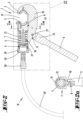
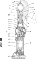
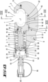
- the device head 1 is preferably designed integrally in one piece with a counterholder 2 for receiving a first tool 3, and furthermore has a cylindrical design 4 in one piece, in which a hydraulic piston 6 acting on a second tool 5 is guided directly or indirectly in a linear manner is relocatable.
- the cylindrical design 4 can directly form a hydraulic cylinder 7, in which the hydraulic piston 6 is guided.
- a toothing formation 8 is provided on it, for the angularly fixed but changeable arrangement of a holding rod 9.
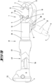
- the device head 1 which is designed in one piece, can be seen overall with reference to a side view Figure 4 or to a longitudinal cross section according to Figure 3 , in which a hydraulic piston axis x is represented as a line, can be designed overall approximately C-shaped, with one C-leg forming the aforementioned counterholder 2 and the opposite C-leg essentially the cylindrical formation 4. These C-legs are over a connecting leg 10 (C-web) running essentially aligned along the hydraulic piston axis x is connected to one another.
- C-web connecting leg 10
- the cylindrical design 4, which in the illustrated embodiment directly forms the running surface for the inside of the wall Hydraulic piston 6 offers, can be designed to be essentially circular cylindrical on the outside of the wall with respect to a cross section transverse to the orientation of the axis x.
- the section of the connecting leg 10 adjoining the cylinder wall of the cylindrical design 4 in this cross section can, as is also preferred, extend essentially in the radial direction with respect to the axis x, the relevant dimension of the wall thickness of the connecting leg 10 being in a direction perpendicular to the Axis x is smaller than it corresponds to the dimension of the outer diameter of the cylindrical training 4.
- the relevant thickness of the connecting leg 10 can correspond to approximately 0.3 to 0.7 times, further approximately 0.5 times the outer diameter of the cylindrical design 4.
- the counterholder 2 forms a first tool carrier 11.
- the first tool 3 can be arranged in this so that it can be snapped into place.
- a second tool carrier 12 can be moved onto this first tool carrier 11 or the first tool 3 accommodated therein, which is preferably formed in one piece and of the same material with a piston shaft 13 which extends in the cylindrical formation 4.
- the tool carrier 12 forms a receptacle A for the second tool 5, which is also preferably held interchangeably here.
- the axial length of the piston shaft 13 can correspond to approximately 1.3 to 2.5 times the maximum displacement path of the hydraulic piston 6.
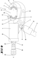
- the second tool carrier 12 can be viewed in accordance with a cross section Figure 2a transverse to the axis x, essentially elongated rectangular.
- Figure 2a transverse to the axis x, essentially elongated rectangular.
- the vertically extending longitudinal edge edges are formed in an elongated straight line, while those viewed transversely are shorter Edge edges are each guided along a curved line.
- These arc lines have a common radius related to the x axis.
- the radius dimension is adapted to the diameter dimension of the surrounding jacket wall of the cylindrical design 4.
- the second tool carrier 12 can, as also shown, on the outside of the wall in the area of a curved surface
- Have holding groove 14 which runs in the axial direction and is open towards the casing wall, into which, in a normal operating state, as shown, there is one in the in Figure 3 shown starting position approximately up to a first tool carrier 11 facing end face 59 of the second tool carrier 12 extending cylindrical formation 4 recorded and guided retaining screw 15 can engage.
- the second tool carrier 12 can be used together with the piston shaft formed in one piece with the tool carrier 12 13 by which in the starting position, for example Figure 3 between the first and the second tool carrier 11 and 12 resulting free device mouth M can be led out, or a corresponding assembly can be carried out in this way. If necessary, this requires a rotation of the tool carrier 12 by preferably approximately 90° about the axis x.
- the section of the cylindrical design 4 which accommodates the second tool carrier can, as also shown, have an enlarged diameter compared to the section of the cylindrical design 4 in which the hydraulic piston 6 is guided.
- the inside diameter of the section of the cylindrical formation 4 surrounding the second tool carrier 12 can correspond to approximately 1.05 to 1.2 times the inside diameter of the section comprising the hydraulic piston 6.
- a step correspondingly results on the inside of the wall, which can also form a stop 16 which projects radially inwards and is essentially annular overall.
- the second tool carrier 12 can step against this stop 16 in the starting position.
- the piston shaft 13 which adjoins the second tool carrier essentially concentrically to the axis x, can be designed as a hollow cylinder 23 essentially over its entire axial length, according to the illustrations. Its outer diameter is smaller than the inner diameter of the relevant section of the cylindrical design 4, so that an annular space 17 is formed surrounding the piston skirt 13.
- the outer diameter of the piston shaft 13 can correspond to approximately 0.5 to 0.8 times the inner diameter of the section of the cylindrical design 4 comprising the hydraulic piston 6.
- This spring 18 is supported with its end facing the second tool carrier 12 via an annular pressure washer 19 on the stop 16 of the device head 1, while the end opposite in the axial direction acts against the facing underside of a cover part 20 of the piston shaft 13.
- the cover part 20 is arranged on the front free end of the piston shaft 13, and preferably protrudes uniformly all around and radially beyond the jacket wall of the piston shaft 13.
- the spring 18 preferably acts against the radial step formed in this way.
- the cover part 20 can be fixed via a clamping screw 21 aligned along the axis x, which clamping screw 21 passes through the cover part 20 in the area of an opening 22 aligned concentrically to the axis x. Furthermore, the clamping screw 21 passes through the hollow cylinder 23 of the piston shaft 13 over its entire length and is in threaded engagement at the end with a correspondingly positioned threaded bore 24 of the second tool carrier 12.
- the spring 18 results in a load on the second tool carrier 12 in the direction of, for example Figure 3 shown starting position, in which the tool carriers 11 and 12 or the tools 3 and 5 accommodated therein occupy a maximum distance from one another when viewed in the axial direction.
- the hydraulic piston 6 is arranged to act on the end of the piston shaft 13 provided with the cover part 20.
- the hydraulic piston 6 can have an overall cup-shaped shape, with a piston wall 25 running concentrically to the axis x, which, as can be seen, is radial can include a portion of the spring 18 on the outside.
- the piston crown 26 acts with its surface on the inside of the pot against the facing end face of the cover part 20, whereby the corresponding piston crown inner surface can also have a central recess 27, for example for receiving the screw head 28 of the clamping screw 21.
- a step-like depression can arise in this regard, in particular for receiving the cover part 20, preferably over its entire axial thickness, and the screw head 28 (compare, for example, the illustration in Figure 11 ).
- the inner surface of the piston crown can also be used as a support surface for the spring 18, so that a restoring force acts on the hydraulic piston 6 in the direction of the starting position via the spring 18 directly or only indirectly via the cover part 20.
- a seal 29 is held in a radially outwardly open, circumferential annular groove for sealing the hydraulic piston 6 against the inner wall 30 of the hydraulic cylinder 7 formed by the cylindrical design 4.
- the toothing formation 8 for fixing the holding rod 9 can, as is also preferred, with reference to a longitudinal cross section Figure 3 laterally offset from the cylindrical formation 4 in the area of the connecting leg 10, preferably in radial overlap with the cylindrical formation 4, that is to say that when the toothing formation 8 is projected in a direction transverse to the alignment of the axis x and in the direction of the Cylindrical design 4, the toothing formation 8 is essentially accommodated in this.
- the toothing formation 8 can, as also shown, only be formed on one side of the connecting leg 10.
- a through opening 31 can first be provided which completely penetrates the connecting leg 10, to which recesses 32, which are evenly spaced apart from one another in the circumferential direction and are preferably of the same design, can be provided in the connecting leg 10 concentrically all around to form the toothing formation 8. So according to the illustration in Figure 7 Twelve such depressions 32 may be provided evenly distributed around the through opening 31.
- the holding rod 9, which can be fixed via the toothing formation 8, has a counter-toothing formation 34 at one holding end 33, which, according to the exemplary embodiment shown, can be formed by a number of projections 35 adapted to the number of recesses 32 of the toothing formation 8.
- These projections 35 can also be designed the same in terms of their cross-sectional design and depth, whereby these projections 35 can be provided uniformly to one another in the circumferential direction, corresponding to the arrangement of the recesses 32.
- the projections 35 are cross-sectionally adapted to the recesses 32, so that a positive connection of the holding rod 9 with the device head 1 can be achieved in the manner of a Hirth toothing due to the engagement of the projections 35 in the recesses 32.
- the mounting rod 9 can be angularly fixed in 30 degree increments - based on the exemplary embodiment.
- Correspondingly different angles ⁇ can be included between the hydraulic piston axis x, which essentially corresponds to the longitudinal axis of the device head 1, and a longitudinal axis y of the holding rod 9.
- a threaded hole 36 can, as is also preferred, be provided in the holder end 33. In the allocation position of the mounting rod 9, this threaded hole 36 overlaps the through opening 31 of the device head 1.
- a fixing screw 37 can be provided, which, starting from the side opposite the toothing formation 8, passes through the through opening 31 and engages in the threaded bore 36 of the holding rod 9.
- a handling knob 38 connected to the end opposite the end cooperating with the threaded bore 36, a tensioning of the holding rod 9, in particular its counter-toothing formation 34, with the toothing formation 8 of the device head 1 can be achieved.
- the holding rod 9 can be pivoted about the geometric pivot axis z given by the fixing screw 37 and extending perpendicular to the axes x and y.
- the device head 1 can also be moved to distant working positions and/or the device head 1 can receive support or the like via the mounting rod 9.
- the cylindrical design 4 can extend further in the direction of extension of the axis x in a direction facing away from the second tool carrier 2 beyond the hydraulic piston 6, in particular the piston crown 26. Accordingly, the hydraulic piston 6 also lies completely in the cylindrical configuration 4 in the starting position.
- connection receptacle 39 for an adapter part 40.
- the free inner diameter a in the area of the connection receptacle 39 can be chosen to be larger, for example by 1.05 to 1.2 times, compared to the free inner diameter b in the area of the section of the cylindrical formation 4 which forms the hydraulic cylinder 7.
- an internal thread can be formed on the inside of the connecting receptacle 39 for cooperation with an external thread of the adapter part 40 in the area of its circumferential adapter part wall 41.
- the adapter part wall 41 can also, as is also preferred, have a seal inserted in a groove on the outside of the wall and open radially outwards 42, which acts against the inner wall 30 of the cylindrical formation 4 or the connection receptacle 39.
- An adapter base 43 aligned transversely to the axis x leaves an inflow opening 44 for a hydraulic medium in the middle, correspondingly penetrated centrally by the geometric axis x.
- This inflow opening 44 is surrounded on the outside or away from the hydraulic piston 6 by a stump-like adapter part connection 45.
- the surface of the adapter base 43 facing away from the hydraulic piston 6 can essentially be aligned with the associated end face of the cylindrical design 4.
- the adapter part 40 can be fixed in the position of use screwed into the connection receptacle 39 by a set screw 46 passing through the wall of the connection receptacle 39.
- the device head 1 can according to in Figures 1 to 8
- the first application shown can be operated via a separate hydraulic unit 47, whereby A hydraulic hose 48 is arranged between the hydraulic unit 47 and the device head 1 for free movement of the device head 1.
- the hydraulic hose 48 is connected at one end to the hydraulic unit 47 and at the other end via a hose connection 58 to the device head 1 via the adapter part 40 in a sealed manner.
- a corresponding hydraulic pressure is generated via the hydraulic unit 47.
- the adapter part 40 can also be used for this purpose, if necessary using the same adapter part 40 as this one for connecting a hydraulic hose 48 but alternatively there is also an adapter part 40 provided separately for the fuselage tool part 49.
- the body tool part 49 can be essentially elongated, rod-shaped, which basically supports one-handed operation of the device.
- a possible arrangement of the mounting rod 9 can provide further support in the area of the device head 1.
- the tool W which is composed of the body tool part 49 and the device head 1, can also be used alone without a holding rod 9, which is why the holding rod 9 is only optionally shown in a dash-dotted line in the illustrations of the second embodiment.
- the tool-free arrangement of the holding rod 9 via the fixing screw 37 offers such an optional arrangement.
- a rod-shaped body tool part 49 is from the one cited at the beginning EP 1519813B1 known.
- the content of this patent is hereby fully incorporated into the disclosure of the present invention, also for the purpose of including features of this patent in the claims of the present invention.
- the body tool part 49 has a grip area 56 for the usual gripping of the tool part housing with one hand.
- An operating button 57 is assigned to the handle area 56 in an ergonomically favorable manner.
- the Figures 12 to 16 show a second embodiment of the device head 1, which differs from the previously described embodiment in particular with regard to the cylindrical design 4 and a guide of the receptacle A or the second tool carrier 12 on the device head 1.
- the basic mode of operation and operation as well as the basic structure for the hydraulic action on the receptacle A essentially corresponds to the first embodiment described above.
- the receptacle A or the second tool carrier 12 is preferably formed in one piece and more preferably made of the same material as the piston shaft 13.
- the cylindrical design 4 extends from the adapter base 43 only to approximately the rear surface 60 facing away from the end face 59 of the receptacle A in the step-like transition from the piston skirt 13 into the receptacle A.
- the Recording A or the second tool carrier 12 (possibly with the second tool 5) between the facing end faces the cylindrical design 4 and the counterholder 2 except for the area of bottom support and guidance in the area of the connecting leg 10.
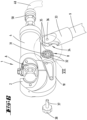
- the receptacle A or the second tool carrier 12 can have a cross-section according to the bottom side, ie facing the connecting leg 10 of the device head 1 Figure 14 essentially T-shaped guide projection 61.
- the guide projection 61 can be guided in a guide groove 62 of the connecting leg 10 directed in the direction of movement d.
- the T-head 67 of the guide projection 61 can be arranged facing the groove bottom of the guide groove 62.
- the T-head 67 of the guide projection can have a cross section corresponding to this Figure 14 waisted T-bar 68 can be connected to the second tool carrier 12.
- the receptacle A or the second tool carrier 12 is initially secured against rotation about the axis x, and there is also linear guidance of the receptacle A when it is displaced in the direction of movement d.
- the guide groove 62 of the device head 1 can be partially formed as an undercut 63 acting transversely to the direction of movement d over the length 1 viewed in the direction of movement d.
- This undercut 63 can be given, for example, by a cross section according to Figure 5 oppositely arranged, mutually directed ribs 64, which are formed at a distance from the groove bottom 69 and are suitable for the waisted area of the guide projection 61 to intervene between the T-head 67 and the receptacle A.
- the undercut 63 can, for example, extend over approximately half the length l of the guide groove 62 in the direction of movement d, up to approximately 2/3 or 3/4 of this entire length l. It is further preferably provided that this undercut section extends in particular over the usual travel path of the receptacle A, correspondingly over the last half of the travel path up to the last 3/4 of the travel path, so that in particular in the critical force-loaded displacement situation of the receptacle A appropriate guidance and protection against a displacement of the receptacle A in a transverse direction to the direction of movement d is provided.
- the guide groove 62 is preferably not provided with ribs 64, so that in this area there is no undercut that interacts with the receptacle A (compare in particular the sectional view in Figure 14 ).
- This offers the advantage of a favorable assembly and disassembly of the receptacle A, which is formed in one piece with the piston skirt 13, while the receptacle A is secured against rotation and tilting in the course of, for example, a pressing or cutting process.
- Figure 16 shows such an assembly or disassembly position of the receptacle A, which is formed in one piece with the piston skirt 13, or of the second Tool carrier 12.
- the adapter base 43 with its seal 42 and the piston base 26 with its seal 29 can first be removed from the hydraulic cylinder 7, after which the clamping screw 21 is exposed for loosening it. After removing the clamping screw 21, the cover part 20 and the spring 18 can be removed. The piston shaft 13 then lies alone and freely in the hydraulic cylinder 7.
- the receptacle A or the second tool carrier 12 can then be offset in a direction transverse to the direction of movement d (see arrow e), so that the guide projection 61 can leave the guide groove 62.
- This lifting or tilting movement in the direction of arrow e can be directly superimposed with an extension direction f (essentially in the axial direction of the piston shaft 13) for removing the receptacle A with the piston shaft 13 through the free device mouth m. Assembly is preferably carried out in the reverse order.
- the opening in the area of the free end of the hose connection 58 can be closed by a plug 65.
- This plug 65 can also be captively connected to the hose connection 58 via a band 66.
Landscapes
- Engineering & Computer Science (AREA)
- Mechanical Engineering (AREA)
- Manufacturing & Machinery (AREA)
- Actuator (AREA)
- Portable Power Tools In General (AREA)
- Earth Drilling (AREA)
- Hand Tools For Fitting Together And Separating, Or Other Hand Tools (AREA)
Claims (15)
- Tête d'outil (1) d'un outil à actionnement hydraulique (W), comprenant un contre-support (2) formé d'un seul tenant sur la tête d'outil (1) et présentant un logement pour un premier outil (3), et un deuxième outil (5) p'ouvant être déplacé vers le contre-support (2) au moyen d'un piston hydraulique (6), une configuration cylindrique (4) étant également prévue d'un seul tenant avec la tête d'outil (1) par rapport au piston hydraulique (6), le deuxième outil (5) pouvant en outre être déplacé au moyen du piston hydraulique (6) entre une position initiale et une position finale de travail, le piston hydraulique (6) pouvant agir sur une tige de piston (13) réalisée d'un seul tenant avec un logement (A) pour le deuxième outil (5), et la tige de piston (13) pouvant être entièrement logée dans la formation cylindrique (4) dans la position initiale, le contre-support formant en outre un premier porte-outil (11) et un deuxième porte-outil (12) pouvant être déplacé vers le premier porte-outil (11), lequel est réalisé d'une seule pièce et dans le même matériau que la tige de piston (13) s'étendant dans la configuration cylindrique (4), le porte-outil (12) formant le logement (A) pour le deuxième outil (5) maintenu de préférence de manière interchangeable, caractérisé en ce que le deuxième porte-outil (12) peut être déplacé dans la configuration cylindrique (4), en ce que le deuxième porte-outil (12) a une forme rectangulaire sensiblement allongée par rapport à une section transversale à un axe de piston hydraulique (x), en ce que des bords longitudinaux s'étendant verticalement à l'état d'utilisation ont une forme rectiligne allongée, tandis que des bords plus courts considérés transversalement à ceux-ci sont guidés chacun le long d'une ligne courbe, et en ce que cette ligne courbe présente un rayon commun se rapportant à l'axe (x), une dimension de rayon étant adaptée à une dimension de diamètre d'une paroi d'enveloppe environnante de la configuration cylindrique (4).
- Tête d'outil selon la revendication 1, caractérisée en ce que la tête d'outil (1) comprend en outre une formation de la denture (8) formée d'un seul tenant pour la disposition angulairement fixe mais variable d'une tige de support (9).
- Tête d'outil selon la revendication 2, caractérisée en ce que la conformation de denture (8) est réalisée dans une section transversale longitudinale de la tête d'outil (1), décalée latéralement mais en recouvrement de la conformation cylindrique (4).
- Tête d'outil selon l'une des revendications 2 ou 3, caractérisée en ce que la conformation de la denture (8) est concentriquement périphérique par rapport à une ouverture centrale de passage (31).
- Tête d'outil selon l'une des revendications précédentes, caractérisée en ce que le logement (A) est agrandi par rapport à la tige de piston (13) et en ce que le logement (A) est maintenu dans la position finale de travail transversalement à la direction de déplacement (d) dans une contre-dépouille (63) réalisée sur la tête d'outil (1).
- Tête d'outil selon l'une des revendications précédentes, caractérisée en ce que le logement (A) peut être déplacé transversalement à la direction de déplacement (d) dans la position initiale pour le montage et le démontage.
- Tête d'outil selon l'une des revendications précédentes, caractérisée en ce que la tête d'outil (1) est reliée à un tuyau hydraulique (48) qui est relié à l'autre extrémité au groupe hydraulique (47) pour permettre le libre mouvement de la tête d'outil (1) par rapport à un groupe hydraulique (47) générant une pression hydraulique.
- Tête d'outil selon l'une quelconque des revendications 1 à 6, caractérisée en ce que la tête d'outil (1) est reliée de manière rigide à une partie d'outil de fuselage (49), dans laquelle, de préférence, le groupe hydraulique (47) est disposé dans la partie d'outil de fuselage (49).
- Tête d'outil selon l'une des revendications précédentes, caractérisée en ce que le deuxième outil (5) est mobile au moyen du piston hydraulique (6) entre une position initiale et une position finale de travail et en ce que le piston hydraulique (6) est entièrement logé dans la formation cylindrique (4) dans la position initiale.
- Tête d'outil selon l'une des revendications 7 à 9, caractérisée en ce que la configuration cylindrique (4) présente, par rapport à la position initiale du piston hydraulique (6), dans le prolongement d'une direction de déplacement (d) du piston hydraulique (6) de la position finale de travail à la position initiale, à l'extérieur de la zone entourant le piston hydraulique (6), un logement de liaison (39) pour la partie d'outil de corps (49) ou le tuyau hydraulique (48).
- Tête d'outil selon la revendication 10, caractérisée en ce que le logement de connexion (39) présente un diamètre intérieur libre (a) qui est plus grand que le diamètre (b) de la configuration cylindrique (4) dans une zone dans laquelle la configuration cylindrique (4) entoure le piston hydraulique (6) dans la position initiale.
- Tête d'outil selon l'une des revendications précédentes, caractérisée en ce que la tige de piston (13) présente une partie de couvercle (20) disposée à l'extrémité opposée au deuxième outil (5).
- Tête d'outil selon l'une des revendications précédentes, caractérisée en ce que la tige de piston (13) est réalisée sous forme de cylindre creux (23) sur une partie de sa longueur.
- Tête d'outil selon l'une des revendications 12 ou 13, caractérisée en ce qu'une vis de serrage (21) maintient la partie de couvercle (20) en traversant le cylindre creux (23).
- Tête d'outil selon l'une des revendications 10 à 14, caractérisée en ce qu'une pièce d'adaptation (40) peut être disposée sur le logement de liaison (39) et en ce qu'une tête de piston (26) est opposée, dans la position initiale, à une surface frontale côté piston de la pièce d'adaptation (40).
Priority Applications (1)
| Application Number | Priority Date | Filing Date | Title |
|---|---|---|---|
| EP24154342.0A EP4349532A3 (fr) | 2019-10-11 | 2020-10-08 | Tête d'outil d'un outil à actionnement hydraulique |
Applications Claiming Priority (2)
| Application Number | Priority Date | Filing Date | Title |
|---|---|---|---|
| DE102019127497.4A DE102019127497A1 (de) | 2019-10-11 | 2019-10-11 | Gerätekopf eines hydraulisch betätigbaren Werkzeugs |
| PCT/EP2020/078276 WO2021069587A1 (fr) | 2019-10-11 | 2020-10-08 | Tête de dispositif d'un outil à commande hydraulique |
Related Child Applications (2)
| Application Number | Title | Priority Date | Filing Date |
|---|---|---|---|
| EP24154342.0A Division EP4349532A3 (fr) | 2019-10-11 | 2020-10-08 | Tête d'outil d'un outil à actionnement hydraulique |
| EP24154342.0A Division-Into EP4349532A3 (fr) | 2019-10-11 | 2020-10-08 | Tête d'outil d'un outil à actionnement hydraulique |
Publications (2)
| Publication Number | Publication Date |
|---|---|
| EP4041471A1 EP4041471A1 (fr) | 2022-08-17 |
| EP4041471B1 true EP4041471B1 (fr) | 2024-03-06 |
Family
ID=72852631
Family Applications (2)
| Application Number | Title | Priority Date | Filing Date |
|---|---|---|---|
| EP24154342.0A Pending EP4349532A3 (fr) | 2019-10-11 | 2020-10-08 | Tête d'outil d'un outil à actionnement hydraulique |
| EP20790233.9A Active EP4041471B1 (fr) | 2019-10-11 | 2020-10-08 | Tête de dispositif d'un outil à commande hydraulique |
Family Applications Before (1)
| Application Number | Title | Priority Date | Filing Date |
|---|---|---|---|
| EP24154342.0A Pending EP4349532A3 (fr) | 2019-10-11 | 2020-10-08 | Tête d'outil d'un outil à actionnement hydraulique |
Country Status (7)
| Country | Link |
|---|---|
| US (2) | US12151356B2 (fr) |
| EP (2) | EP4349532A3 (fr) |
| JP (1) | JP7620009B2 (fr) |
| KR (1) | KR20220080152A (fr) |
| CN (2) | CN120901174A (fr) |
| DE (1) | DE102019127497A1 (fr) |
| WO (1) | WO2021069587A1 (fr) |
Families Citing this family (9)
| Publication number | Priority date | Publication date | Assignee | Title |
|---|---|---|---|---|
| DE102020131036A1 (de) * | 2020-10-12 | 2022-04-14 | Gustav Klauke Gmbh | Hydraulisch betätigbare, als Handgerät ausgebildete Arbeitsvorrichtung |
| USD1042068S1 (en) | 2021-05-19 | 2024-09-17 | Gustav Klauke Gmbh | Hydraulic press tool |
| USD1037815S1 (en) | 2021-05-28 | 2024-08-06 | Gustav Klauke Gmbh | Press head for a hydraulic press tool |
| EP4245466B1 (fr) * | 2022-03-14 | 2025-01-29 | Dubuis et Cie | Outil hydraulique portable comprenant une poignée |
| US12263570B2 (en) | 2022-06-06 | 2025-04-01 | Enerpac Tool Group Corp. | Hydraulic tools |
| WO2023237775A1 (fr) | 2022-06-10 | 2023-12-14 | Gustav Klauke Gmbh | Outil à main |
| WO2023237776A1 (fr) | 2022-06-10 | 2023-12-14 | Gustav Klauke Gmbh | Outil à main |
| WO2024112516A1 (fr) * | 2022-11-23 | 2024-05-30 | Hubbell Incorporated | Élément de réglage d'application de force dans un ensemble à va-et-vient |
| KR102699972B1 (ko) * | 2024-06-07 | 2024-08-29 | (주)대진유압기계 | 휴대용 동배관 락링 압착 유압 툴 |
Family Cites Families (19)
| Publication number | Priority date | Publication date | Assignee | Title |
|---|---|---|---|---|
| US3017905A (en) * | 1957-03-05 | 1962-01-23 | Nat Telephone Supply Co | Hot line stick |
| US2968202A (en) * | 1958-04-11 | 1961-01-17 | Amp Inc | Hydraulic crimping tool for crimping t-tap connectors |
| US3326029A (en) * | 1964-08-05 | 1967-06-20 | Porter Inc H K | Hydraulic press |
| DE10216213A1 (de) | 2002-04-10 | 2003-10-23 | Klauke Gmbh Gustav | Elektrohydraulisches Verpressgerät und Verfahren zum Betreiben desselben |
| US5062290A (en) * | 1990-06-25 | 1991-11-05 | Burndy Corporation | Hydraulic crimping press for electrical connectors |
| US5337566A (en) * | 1993-03-18 | 1994-08-16 | Burndy Corporation | Powder actuated compression tool |
| DE19944229B4 (de) | 1999-09-15 | 2016-07-28 | Gustav Klauke Gmbh | Hydraulisches Handpressgerät und auswechselbarer Gerätekopf hierfür |
| US7134314B1 (en) * | 2005-08-26 | 2006-11-14 | Fci Americas Technology, Inc. | Hydraulic tool automatic adjusting die holder |
| US7124619B1 (en) * | 2005-08-26 | 2006-10-24 | Fci Americas Technology, Inc. | Hydraulic tool working head |
| CN102909710B (zh) * | 2011-08-06 | 2015-04-22 | 苏州宝时得电动工具有限公司 | 动力工具 |
| US20160344170A1 (en) | 2012-10-12 | 2016-11-24 | Carl Russel Tamm | Remote Control Tool Assembly For Use In Live Line Environments |
| US9731411B2 (en) * | 2013-12-10 | 2017-08-15 | Izumi Products Company | Hydraulic tool |
| US9393683B2 (en) * | 2014-05-02 | 2016-07-19 | M. W. Bevins Co. | Conductive boot for power tool protection |
| JP6720133B2 (ja) * | 2014-07-07 | 2020-07-08 | センブレ エス.ピー.エー. | 流体力学圧縮工具の動作方法、及び、流体力学圧縮工具 |
| US9774159B2 (en) * | 2015-01-16 | 2017-09-26 | Ridge Tool Company | Deflection compensating press tools |
| CN105500278B (zh) * | 2016-01-05 | 2017-08-15 | 艾默生管道工具(上海)有限公司 | 液压工具 |
| EP3333994B1 (fr) * | 2016-12-09 | 2020-03-18 | CEMBRE S.p.A. | Tête de travail pour outil de coupe ou de compression |
| DE102018102162A1 (de) * | 2017-10-02 | 2019-04-04 | Gustav Klauke Gmbh | Handwerkzeug |
| CN208773362U (zh) * | 2018-08-31 | 2019-04-23 | 上海沃恒机械设备有限公司 | 液压钳 |
-
2019
- 2019-10-11 DE DE102019127497.4A patent/DE102019127497A1/de active Pending
-
2020
- 2020-10-08 CN CN202511012639.6A patent/CN120901174A/zh active Pending
- 2020-10-08 US US17/754,496 patent/US12151356B2/en active Active
- 2020-10-08 CN CN202080081161.1A patent/CN114728325B/zh active Active
- 2020-10-08 EP EP24154342.0A patent/EP4349532A3/fr active Pending
- 2020-10-08 WO PCT/EP2020/078276 patent/WO2021069587A1/fr not_active Ceased
- 2020-10-08 EP EP20790233.9A patent/EP4041471B1/fr active Active
- 2020-10-08 KR KR1020227015520A patent/KR20220080152A/ko active Pending
- 2020-10-08 JP JP2022520520A patent/JP7620009B2/ja active Active
-
2024
- 2024-10-17 US US18/918,452 patent/US20250042010A1/en active Pending
Also Published As
| Publication number | Publication date |
|---|---|
| US20230405788A1 (en) | 2023-12-21 |
| CN120901174A (zh) | 2025-11-07 |
| CN114728325B (zh) | 2025-07-22 |
| WO2021069587A1 (fr) | 2021-04-15 |
| US12151356B2 (en) | 2024-11-26 |
| EP4041471A1 (fr) | 2022-08-17 |
| KR20220080152A (ko) | 2022-06-14 |
| US20250042010A1 (en) | 2025-02-06 |
| EP4349532A2 (fr) | 2024-04-10 |
| JP2023504764A (ja) | 2023-02-07 |
| JP7620009B2 (ja) | 2025-01-22 |
| EP4349532A3 (fr) | 2024-09-04 |
| CN114728325A (zh) | 2022-07-08 |
| DE102019127497A1 (de) | 2021-04-15 |
Similar Documents
| Publication | Publication Date | Title |
|---|---|---|
| EP4349532A2 (fr) | Tête d'outil d'un outil à actionnement hydraulique | |
| DE2901306C2 (fr) | ||
| DE2311494A1 (de) | Hydraulische hebevorrichtung | |
| DE3249144T1 (de) | Druckfester anschraubfilter | |
| EP0054254A1 (fr) | Bêche | |
| DE3345959C2 (de) | Zylinderkopfbefestigungskonstruktion | |
| EP3334569B1 (fr) | Dispositif pour appliquer une force de pressage et paire de mâchoires de pressage | |
| EP1870526B1 (fr) | Robinet sanitaire | |
| DE29614077U1 (de) | Tankverschluß für einen Einfüllstutzen eines Behälters | |
| DE102007016431A1 (de) | Fluidbetätigter Linearantrieb | |
| DE102012112209A1 (de) | Bohrfutter | |
| EP3964650B1 (fr) | Système de changement rapide permettant de changer les accessoires sur une machine de construction | |
| DE20102698U1 (de) | Druckmittelbetätigbare kombinierte Zentrier- und Spannvorrichtung | |
| DE3420646C2 (fr) | ||
| DE10317342B4 (de) | Schnellspannsystem mit Handbetätigung | |
| DE2909464A1 (de) | Schwenkspanner, insbesondere zum spannen eines werkstueckes auf einem maschinentisch einer werkzeugmaschine | |
| DE3936630A1 (de) | Werkzeugtraeger fuer rotationswerkzeuge, insbesondere fuer kreissaegeblaetter, zerspaner usw. | |
| DE3820898C2 (fr) | ||
| AT410772B (de) | Halter zur befestigung eines mit einem haltezapfen versehenen werkstückes | |
| DE102016219220A1 (de) | Hydraulikantrieb | |
| DE3330718C2 (fr) | ||
| DE19681702B4 (de) | Zweikomponenten-Aerosol-Dose | |
| CH685355A5 (de) | Arbeitszylinder. | |
| DE19844204C2 (de) | Werkzeug zur Herstellung eines Schaumformteils | |
| DE112013001201T5 (de) | Kolbenhaltevorrichtung und -verfahren |
Legal Events
| Date | Code | Title | Description |
|---|---|---|---|
| STAA | Information on the status of an ep patent application or granted ep patent |
Free format text: STATUS: UNKNOWN |
|
| STAA | Information on the status of an ep patent application or granted ep patent |
Free format text: STATUS: THE INTERNATIONAL PUBLICATION HAS BEEN MADE |
|
| PUAI | Public reference made under article 153(3) epc to a published international application that has entered the european phase |
Free format text: ORIGINAL CODE: 0009012 |
|
| STAA | Information on the status of an ep patent application or granted ep patent |
Free format text: STATUS: REQUEST FOR EXAMINATION WAS MADE |
|
| 17P | Request for examination filed |
Effective date: 20220504 |
|
| AK | Designated contracting states |
Kind code of ref document: A1 Designated state(s): AL AT BE BG CH CY CZ DE DK EE ES FI FR GB GR HR HU IE IS IT LI LT LU LV MC MK MT NL NO PL PT RO RS SE SI SK SM TR |
|
| DAV | Request for validation of the european patent (deleted) | ||
| DAX | Request for extension of the european patent (deleted) | ||
| GRAP | Despatch of communication of intention to grant a patent |
Free format text: ORIGINAL CODE: EPIDOSNIGR1 |
|
| STAA | Information on the status of an ep patent application or granted ep patent |
Free format text: STATUS: GRANT OF PATENT IS INTENDED |
|
| RIC1 | Information provided on ipc code assigned before grant |
Ipc: B25B 27/10 20060101ALI20230904BHEP Ipc: B25B 27/14 20060101ALI20230904BHEP Ipc: B25F 5/00 20060101ALI20230904BHEP Ipc: H01R 43/042 20060101ALI20230904BHEP Ipc: B25B 27/02 20060101ALI20230904BHEP Ipc: B25F 5/02 20060101ALI20230904BHEP Ipc: B21D 39/04 20060101AFI20230904BHEP |
|
| INTG | Intention to grant announced |
Effective date: 20230928 |
|
| GRAS | Grant fee paid |
Free format text: ORIGINAL CODE: EPIDOSNIGR3 |
|
| GRAA | (expected) grant |
Free format text: ORIGINAL CODE: 0009210 |
|
| STAA | Information on the status of an ep patent application or granted ep patent |
Free format text: STATUS: THE PATENT HAS BEEN GRANTED |
|
| AK | Designated contracting states |
Kind code of ref document: B1 Designated state(s): AL AT BE BG CH CY CZ DE DK EE ES FI FR GB GR HR HU IE IS IT LI LT LU LV MC MK MT NL NO PL PT RO RS SE SI SK SM TR |
|
| P01 | Opt-out of the competence of the unified patent court (upc) registered |
Effective date: 20240129 |
|
| REG | Reference to a national code |
Ref country code: CH Ref legal event code: EP |
|
| REG | Reference to a national code |
Ref country code: DE Ref legal event code: R096 Ref document number: 502020007269 Country of ref document: DE |
|
| REG | Reference to a national code |
Ref country code: IE Ref legal event code: FG4D Free format text: LANGUAGE OF EP DOCUMENT: GERMAN |
|
| REG | Reference to a national code |
Ref country code: LT Ref legal event code: MG9D |
|
| PG25 | Lapsed in a contracting state [announced via postgrant information from national office to epo] |
Ref country code: LT Free format text: LAPSE BECAUSE OF FAILURE TO SUBMIT A TRANSLATION OF THE DESCRIPTION OR TO PAY THE FEE WITHIN THE PRESCRIBED TIME-LIMIT Effective date: 20240306 |
|
| REG | Reference to a national code |
Ref country code: NL Ref legal event code: MP Effective date: 20240306 |
|
| PG25 | Lapsed in a contracting state [announced via postgrant information from national office to epo] |
Ref country code: GR Free format text: LAPSE BECAUSE OF FAILURE TO SUBMIT A TRANSLATION OF THE DESCRIPTION OR TO PAY THE FEE WITHIN THE PRESCRIBED TIME-LIMIT Effective date: 20240607 |
|
| PG25 | Lapsed in a contracting state [announced via postgrant information from national office to epo] |
Ref country code: HR Free format text: LAPSE BECAUSE OF FAILURE TO SUBMIT A TRANSLATION OF THE DESCRIPTION OR TO PAY THE FEE WITHIN THE PRESCRIBED TIME-LIMIT Effective date: 20240306 Ref country code: RS Free format text: LAPSE BECAUSE OF FAILURE TO SUBMIT A TRANSLATION OF THE DESCRIPTION OR TO PAY THE FEE WITHIN THE PRESCRIBED TIME-LIMIT Effective date: 20240606 |
|
| PG25 | Lapsed in a contracting state [announced via postgrant information from national office to epo] |
Ref country code: ES Free format text: LAPSE BECAUSE OF FAILURE TO SUBMIT A TRANSLATION OF THE DESCRIPTION OR TO PAY THE FEE WITHIN THE PRESCRIBED TIME-LIMIT Effective date: 20240306 |
|
| PG25 | Lapsed in a contracting state [announced via postgrant information from national office to epo] |
Ref country code: RS Free format text: LAPSE BECAUSE OF FAILURE TO SUBMIT A TRANSLATION OF THE DESCRIPTION OR TO PAY THE FEE WITHIN THE PRESCRIBED TIME-LIMIT Effective date: 20240606 Ref country code: NO Free format text: LAPSE BECAUSE OF FAILURE TO SUBMIT A TRANSLATION OF THE DESCRIPTION OR TO PAY THE FEE WITHIN THE PRESCRIBED TIME-LIMIT Effective date: 20240606 Ref country code: LT Free format text: LAPSE BECAUSE OF FAILURE TO SUBMIT A TRANSLATION OF THE DESCRIPTION OR TO PAY THE FEE WITHIN THE PRESCRIBED TIME-LIMIT Effective date: 20240306 Ref country code: HR Free format text: LAPSE BECAUSE OF FAILURE TO SUBMIT A TRANSLATION OF THE DESCRIPTION OR TO PAY THE FEE WITHIN THE PRESCRIBED TIME-LIMIT Effective date: 20240306 Ref country code: GR Free format text: LAPSE BECAUSE OF FAILURE TO SUBMIT A TRANSLATION OF THE DESCRIPTION OR TO PAY THE FEE WITHIN THE PRESCRIBED TIME-LIMIT Effective date: 20240607 Ref country code: FI Free format text: LAPSE BECAUSE OF FAILURE TO SUBMIT A TRANSLATION OF THE DESCRIPTION OR TO PAY THE FEE WITHIN THE PRESCRIBED TIME-LIMIT Effective date: 20240306 Ref country code: ES Free format text: LAPSE BECAUSE OF FAILURE TO SUBMIT A TRANSLATION OF THE DESCRIPTION OR TO PAY THE FEE WITHIN THE PRESCRIBED TIME-LIMIT Effective date: 20240306 Ref country code: BG Free format text: LAPSE BECAUSE OF FAILURE TO SUBMIT A TRANSLATION OF THE DESCRIPTION OR TO PAY THE FEE WITHIN THE PRESCRIBED TIME-LIMIT Effective date: 20240306 |
|
| PG25 | Lapsed in a contracting state [announced via postgrant information from national office to epo] |
Ref country code: SE Free format text: LAPSE BECAUSE OF FAILURE TO SUBMIT A TRANSLATION OF THE DESCRIPTION OR TO PAY THE FEE WITHIN THE PRESCRIBED TIME-LIMIT Effective date: 20240306 Ref country code: LV Free format text: LAPSE BECAUSE OF FAILURE TO SUBMIT A TRANSLATION OF THE DESCRIPTION OR TO PAY THE FEE WITHIN THE PRESCRIBED TIME-LIMIT Effective date: 20240306 |
|
| PG25 | Lapsed in a contracting state [announced via postgrant information from national office to epo] |
Ref country code: NL Free format text: LAPSE BECAUSE OF FAILURE TO SUBMIT A TRANSLATION OF THE DESCRIPTION OR TO PAY THE FEE WITHIN THE PRESCRIBED TIME-LIMIT Effective date: 20240306 |
|
| PG25 | Lapsed in a contracting state [announced via postgrant information from national office to epo] |
Ref country code: NL Free format text: LAPSE BECAUSE OF FAILURE TO SUBMIT A TRANSLATION OF THE DESCRIPTION OR TO PAY THE FEE WITHIN THE PRESCRIBED TIME-LIMIT Effective date: 20240306 |
|
| PG25 | Lapsed in a contracting state [announced via postgrant information from national office to epo] |
Ref country code: IS Free format text: LAPSE BECAUSE OF FAILURE TO SUBMIT A TRANSLATION OF THE DESCRIPTION OR TO PAY THE FEE WITHIN THE PRESCRIBED TIME-LIMIT Effective date: 20240706 |
|
| PG25 | Lapsed in a contracting state [announced via postgrant information from national office to epo] |
Ref country code: PT Free format text: LAPSE BECAUSE OF FAILURE TO SUBMIT A TRANSLATION OF THE DESCRIPTION OR TO PAY THE FEE WITHIN THE PRESCRIBED TIME-LIMIT Effective date: 20240708 Ref country code: SM Free format text: LAPSE BECAUSE OF FAILURE TO SUBMIT A TRANSLATION OF THE DESCRIPTION OR TO PAY THE FEE WITHIN THE PRESCRIBED TIME-LIMIT Effective date: 20240306 |
|
| PG25 | Lapsed in a contracting state [announced via postgrant information from national office to epo] |
Ref country code: EE Free format text: LAPSE BECAUSE OF FAILURE TO SUBMIT A TRANSLATION OF THE DESCRIPTION OR TO PAY THE FEE WITHIN THE PRESCRIBED TIME-LIMIT Effective date: 20240306 Ref country code: CZ Free format text: LAPSE BECAUSE OF FAILURE TO SUBMIT A TRANSLATION OF THE DESCRIPTION OR TO PAY THE FEE WITHIN THE PRESCRIBED TIME-LIMIT Effective date: 20240306 |
|
| PG25 | Lapsed in a contracting state [announced via postgrant information from national office to epo] |
Ref country code: PL Free format text: LAPSE BECAUSE OF FAILURE TO SUBMIT A TRANSLATION OF THE DESCRIPTION OR TO PAY THE FEE WITHIN THE PRESCRIBED TIME-LIMIT Effective date: 20240306 |
|
| PG25 | Lapsed in a contracting state [announced via postgrant information from national office to epo] |
Ref country code: SK Free format text: LAPSE BECAUSE OF FAILURE TO SUBMIT A TRANSLATION OF THE DESCRIPTION OR TO PAY THE FEE WITHIN THE PRESCRIBED TIME-LIMIT Effective date: 20240306 |
|
| PG25 | Lapsed in a contracting state [announced via postgrant information from national office to epo] |
Ref country code: SM Free format text: LAPSE BECAUSE OF FAILURE TO SUBMIT A TRANSLATION OF THE DESCRIPTION OR TO PAY THE FEE WITHIN THE PRESCRIBED TIME-LIMIT Effective date: 20240306 Ref country code: SK Free format text: LAPSE BECAUSE OF FAILURE TO SUBMIT A TRANSLATION OF THE DESCRIPTION OR TO PAY THE FEE WITHIN THE PRESCRIBED TIME-LIMIT Effective date: 20240306 Ref country code: RO Free format text: LAPSE BECAUSE OF FAILURE TO SUBMIT A TRANSLATION OF THE DESCRIPTION OR TO PAY THE FEE WITHIN THE PRESCRIBED TIME-LIMIT Effective date: 20240306 Ref country code: PT Free format text: LAPSE BECAUSE OF FAILURE TO SUBMIT A TRANSLATION OF THE DESCRIPTION OR TO PAY THE FEE WITHIN THE PRESCRIBED TIME-LIMIT Effective date: 20240708 Ref country code: PL Free format text: LAPSE BECAUSE OF FAILURE TO SUBMIT A TRANSLATION OF THE DESCRIPTION OR TO PAY THE FEE WITHIN THE PRESCRIBED TIME-LIMIT Effective date: 20240306 Ref country code: IS Free format text: LAPSE BECAUSE OF FAILURE TO SUBMIT A TRANSLATION OF THE DESCRIPTION OR TO PAY THE FEE WITHIN THE PRESCRIBED TIME-LIMIT Effective date: 20240706 Ref country code: EE Free format text: LAPSE BECAUSE OF FAILURE TO SUBMIT A TRANSLATION OF THE DESCRIPTION OR TO PAY THE FEE WITHIN THE PRESCRIBED TIME-LIMIT Effective date: 20240306 Ref country code: CZ Free format text: LAPSE BECAUSE OF FAILURE TO SUBMIT A TRANSLATION OF THE DESCRIPTION OR TO PAY THE FEE WITHIN THE PRESCRIBED TIME-LIMIT Effective date: 20240306 |
|
| REG | Reference to a national code |
Ref country code: DE Ref legal event code: R097 Ref document number: 502020007269 Country of ref document: DE |
|
| PLBE | No opposition filed within time limit |
Free format text: ORIGINAL CODE: 0009261 |
|
| STAA | Information on the status of an ep patent application or granted ep patent |
Free format text: STATUS: NO OPPOSITION FILED WITHIN TIME LIMIT |
|
| PG25 | Lapsed in a contracting state [announced via postgrant information from national office to epo] |
Ref country code: DK Free format text: LAPSE BECAUSE OF FAILURE TO SUBMIT A TRANSLATION OF THE DESCRIPTION OR TO PAY THE FEE WITHIN THE PRESCRIBED TIME-LIMIT Effective date: 20240306 |
|
| PG25 | Lapsed in a contracting state [announced via postgrant information from national office to epo] |
Ref country code: DK Free format text: LAPSE BECAUSE OF FAILURE TO SUBMIT A TRANSLATION OF THE DESCRIPTION OR TO PAY THE FEE WITHIN THE PRESCRIBED TIME-LIMIT Effective date: 20240306 |
|
| 26N | No opposition filed |
Effective date: 20241209 |
|
| PG25 | Lapsed in a contracting state [announced via postgrant information from national office to epo] |
Ref country code: SI Free format text: LAPSE BECAUSE OF FAILURE TO SUBMIT A TRANSLATION OF THE DESCRIPTION OR TO PAY THE FEE WITHIN THE PRESCRIBED TIME-LIMIT Effective date: 20240306 |
|
| REG | Reference to a national code |
Ref country code: CH Ref legal event code: PL |
|
| PG25 | Lapsed in a contracting state [announced via postgrant information from national office to epo] |
Ref country code: MC Free format text: LAPSE BECAUSE OF FAILURE TO SUBMIT A TRANSLATION OF THE DESCRIPTION OR TO PAY THE FEE WITHIN THE PRESCRIBED TIME-LIMIT Effective date: 20240306 |
|
| PG25 | Lapsed in a contracting state [announced via postgrant information from national office to epo] |
Ref country code: LU Free format text: LAPSE BECAUSE OF NON-PAYMENT OF DUE FEES Effective date: 20241008 Ref country code: BE Free format text: LAPSE BECAUSE OF NON-PAYMENT OF DUE FEES Effective date: 20241031 |
|
| PG25 | Lapsed in a contracting state [announced via postgrant information from national office to epo] |
Ref country code: CH Free format text: LAPSE BECAUSE OF NON-PAYMENT OF DUE FEES Effective date: 20241031 |
|
| REG | Reference to a national code |
Ref country code: BE Ref legal event code: MM Effective date: 20241031 |
|
| PG25 | Lapsed in a contracting state [announced via postgrant information from national office to epo] |
Ref country code: IE Free format text: LAPSE BECAUSE OF NON-PAYMENT OF DUE FEES Effective date: 20241008 |
|
| PGFP | Annual fee paid to national office [announced via postgrant information from national office to epo] |
Ref country code: DE Payment date: 20251219 Year of fee payment: 6 |
|
| PGFP | Annual fee paid to national office [announced via postgrant information from national office to epo] |
Ref country code: GB Payment date: 20251024 Year of fee payment: 6 |
|
| PGFP | Annual fee paid to national office [announced via postgrant information from national office to epo] |
Ref country code: AT Payment date: 20260113 Year of fee payment: 5 |
|
| PGFP | Annual fee paid to national office [announced via postgrant information from national office to epo] |
Ref country code: IT Payment date: 20251027 Year of fee payment: 6 |
|
| PGFP | Annual fee paid to national office [announced via postgrant information from national office to epo] |
Ref country code: FR Payment date: 20251020 Year of fee payment: 6 |
|
| PG25 | Lapsed in a contracting state [announced via postgrant information from national office to epo] |
Ref country code: CY Free format text: LAPSE BECAUSE OF FAILURE TO SUBMIT A TRANSLATION OF THE DESCRIPTION OR TO PAY THE FEE WITHIN THE PRESCRIBED TIME-LIMIT; INVALID AB INITIO Effective date: 20201008 |
|
| PG25 | Lapsed in a contracting state [announced via postgrant information from national office to epo] |
Ref country code: HU Free format text: LAPSE BECAUSE OF FAILURE TO SUBMIT A TRANSLATION OF THE DESCRIPTION OR TO PAY THE FEE WITHIN THE PRESCRIBED TIME-LIMIT; INVALID AB INITIO Effective date: 20201008 |