EP4041509B1 - Fabrication additive d'elements de construction en beton - Google Patents
Fabrication additive d'elements de construction en beton Download PDFInfo
- Publication number
- EP4041509B1 EP4041509B1 EP20788787.8A EP20788787A EP4041509B1 EP 4041509 B1 EP4041509 B1 EP 4041509B1 EP 20788787 A EP20788787 A EP 20788787A EP 4041509 B1 EP4041509 B1 EP 4041509B1
- Authority
- EP
- European Patent Office
- Prior art keywords
- wall
- cavity
- reinforcement
- wall surfaces
- extending
- Prior art date
- Legal status (The legal status is an assumption and is not a legal conclusion. Google has not performed a legal analysis and makes no representation as to the accuracy of the status listed.)
- Active
Links
Images



Classifications
-
- E—FIXED CONSTRUCTIONS
- E04—BUILDING
- E04G—SCAFFOLDING; FORMS; SHUTTERING; BUILDING IMPLEMENTS OR AIDS, OR THEIR USE; HANDLING BUILDING MATERIALS ON THE SITE; REPAIRING, BREAKING-UP OR OTHER WORK ON EXISTING BUILDINGS
- E04G21/00—Preparing, conveying, or working-up building materials or building elements in situ; Other devices or measures for constructional work
- E04G21/02—Conveying or working-up concrete or similar masses able to be heaped or cast
-
- E—FIXED CONSTRUCTIONS
- E04—BUILDING
- E04B—GENERAL BUILDING CONSTRUCTIONS; WALLS, e.g. PARTITIONS; ROOFS; FLOORS; CEILINGS; INSULATION OR OTHER PROTECTION OF BUILDINGS
- E04B2/00—Walls, e.g. partitions, for buildings; Wall construction with regard to insulation; Connections specially adapted to walls
- E04B2/84—Walls made by casting, pouring, or tamping in situ
- E04B2/86—Walls made by casting, pouring, or tamping in situ made in permanent forms
-
- B—PERFORMING OPERATIONS; TRANSPORTING
- B28—WORKING CEMENT, CLAY, OR STONE
- B28B—SHAPING CLAY OR OTHER CERAMIC COMPOSITIONS; SHAPING SLAG; SHAPING MIXTURES CONTAINING CEMENTITIOUS MATERIAL, e.g. PLASTER
- B28B1/00—Producing shaped prefabricated articles from the material
- B28B1/001—Rapid manufacturing of 3D objects by additive depositing, agglomerating or laminating of material
-
- B—PERFORMING OPERATIONS; TRANSPORTING
- B28—WORKING CEMENT, CLAY, OR STONE
- B28B—SHAPING CLAY OR OTHER CERAMIC COMPOSITIONS; SHAPING SLAG; SHAPING MIXTURES CONTAINING CEMENTITIOUS MATERIAL, e.g. PLASTER
- B28B11/00—Apparatus or processes for treating or working the shaped or preshaped articles
- B28B11/04—Apparatus or processes for treating or working the shaped or preshaped articles for coating or applying engobing layers
- B28B11/042—Apparatus or processes for treating or working the shaped or preshaped articles for coating or applying engobing layers with insulating material
-
- B—PERFORMING OPERATIONS; TRANSPORTING
- B28—WORKING CEMENT, CLAY, OR STONE
- B28B—SHAPING CLAY OR OTHER CERAMIC COMPOSITIONS; SHAPING SLAG; SHAPING MIXTURES CONTAINING CEMENTITIOUS MATERIAL, e.g. PLASTER
- B28B23/00—Arrangements specially adapted for the production of shaped articles with elements wholly or partly embedded in the moulding material; Production of reinforced objects
- B28B23/02—Arrangements specially adapted for the production of shaped articles with elements wholly or partly embedded in the moulding material; Production of reinforced objects wherein the elements are reinforcing members
- B28B23/028—Arrangements specially adapted for the production of shaped articles with elements wholly or partly embedded in the moulding material; Production of reinforced objects wherein the elements are reinforcing members for double - wall articles
-
- C—CHEMISTRY; METALLURGY
- C04—CEMENTS; CONCRETE; ARTIFICIAL STONE; CERAMICS; REFRACTORIES
- C04B—LIME, MAGNESIA; SLAG; CEMENTS; COMPOSITIONS THEREOF, e.g. MORTARS, CONCRETE OR LIKE BUILDING MATERIALS; ARTIFICIAL STONE; CERAMICS; REFRACTORIES; TREATMENT OF NATURAL STONE
- C04B28/00—Compositions of mortars, concrete or artificial stone, containing inorganic binders or the reaction product of an inorganic and an organic binder, e.g. polycarboxylate cements
- C04B28/02—Compositions of mortars, concrete or artificial stone, containing inorganic binders or the reaction product of an inorganic and an organic binder, e.g. polycarboxylate cements containing hydraulic cements other than calcium sulfates
-
- C—CHEMISTRY; METALLURGY
- C04—CEMENTS; CONCRETE; ARTIFICIAL STONE; CERAMICS; REFRACTORIES
- C04B—LIME, MAGNESIA; SLAG; CEMENTS; COMPOSITIONS THEREOF, e.g. MORTARS, CONCRETE OR LIKE BUILDING MATERIALS; ARTIFICIAL STONE; CERAMICS; REFRACTORIES; TREATMENT OF NATURAL STONE
- C04B28/00—Compositions of mortars, concrete or artificial stone, containing inorganic binders or the reaction product of an inorganic and an organic binder, e.g. polycarboxylate cements
- C04B28/02—Compositions of mortars, concrete or artificial stone, containing inorganic binders or the reaction product of an inorganic and an organic binder, e.g. polycarboxylate cements containing hydraulic cements other than calcium sulfates
- C04B28/04—Portland cements
-
- C—CHEMISTRY; METALLURGY
- C04—CEMENTS; CONCRETE; ARTIFICIAL STONE; CERAMICS; REFRACTORIES
- C04B—LIME, MAGNESIA; SLAG; CEMENTS; COMPOSITIONS THEREOF, e.g. MORTARS, CONCRETE OR LIKE BUILDING MATERIALS; ARTIFICIAL STONE; CERAMICS; REFRACTORIES; TREATMENT OF NATURAL STONE
- C04B28/00—Compositions of mortars, concrete or artificial stone, containing inorganic binders or the reaction product of an inorganic and an organic binder, e.g. polycarboxylate cements
- C04B28/02—Compositions of mortars, concrete or artificial stone, containing inorganic binders or the reaction product of an inorganic and an organic binder, e.g. polycarboxylate cements containing hydraulic cements other than calcium sulfates
- C04B28/06—Aluminous cements
-
- C—CHEMISTRY; METALLURGY
- C04—CEMENTS; CONCRETE; ARTIFICIAL STONE; CERAMICS; REFRACTORIES
- C04B—LIME, MAGNESIA; SLAG; CEMENTS; COMPOSITIONS THEREOF, e.g. MORTARS, CONCRETE OR LIKE BUILDING MATERIALS; ARTIFICIAL STONE; CERAMICS; REFRACTORIES; TREATMENT OF NATURAL STONE
- C04B28/00—Compositions of mortars, concrete or artificial stone, containing inorganic binders or the reaction product of an inorganic and an organic binder, e.g. polycarboxylate cements
- C04B28/02—Compositions of mortars, concrete or artificial stone, containing inorganic binders or the reaction product of an inorganic and an organic binder, e.g. polycarboxylate cements containing hydraulic cements other than calcium sulfates
- C04B28/10—Lime cements or magnesium oxide cements
- C04B28/12—Hydraulic lime
-
- C—CHEMISTRY; METALLURGY
- C04—CEMENTS; CONCRETE; ARTIFICIAL STONE; CERAMICS; REFRACTORIES
- C04B—LIME, MAGNESIA; SLAG; CEMENTS; COMPOSITIONS THEREOF, e.g. MORTARS, CONCRETE OR LIKE BUILDING MATERIALS; ARTIFICIAL STONE; CERAMICS; REFRACTORIES; TREATMENT OF NATURAL STONE
- C04B38/00—Porous mortars, concrete, artificial stone or ceramic ware; Preparation thereof
-
- E—FIXED CONSTRUCTIONS
- E04—BUILDING
- E04B—GENERAL BUILDING CONSTRUCTIONS; WALLS, e.g. PARTITIONS; ROOFS; FLOORS; CEILINGS; INSULATION OR OTHER PROTECTION OF BUILDINGS
- E04B1/00—Constructions in general; Structures which are not restricted either to walls, e.g. partitions, or floors or ceilings or roofs
- E04B1/62—Insulation or other protection; Elements or use of specified material therefor
- E04B1/74—Heat, sound or noise insulation, absorption, or reflection; Other building methods affording favourable thermal or acoustical conditions, e.g. accumulating of heat within walls
-
- E—FIXED CONSTRUCTIONS
- E04—BUILDING
- E04B—GENERAL BUILDING CONSTRUCTIONS; WALLS, e.g. PARTITIONS; ROOFS; FLOORS; CEILINGS; INSULATION OR OTHER PROTECTION OF BUILDINGS
- E04B1/00—Constructions in general; Structures which are not restricted either to walls, e.g. partitions, or floors or ceilings or roofs
- E04B1/62—Insulation or other protection; Elements or use of specified material therefor
- E04B1/74—Heat, sound or noise insulation, absorption, or reflection; Other building methods affording favourable thermal or acoustical conditions, e.g. accumulating of heat within walls
- E04B1/76—Heat, sound or noise insulation, absorption, or reflection; Other building methods affording favourable thermal or acoustical conditions, e.g. accumulating of heat within walls specifically with respect to heat only
-
- E—FIXED CONSTRUCTIONS
- E04—BUILDING
- E04B—GENERAL BUILDING CONSTRUCTIONS; WALLS, e.g. PARTITIONS; ROOFS; FLOORS; CEILINGS; INSULATION OR OTHER PROTECTION OF BUILDINGS
- E04B2/00—Walls, e.g. partitions, for buildings; Wall construction with regard to insulation; Connections specially adapted to walls
- E04B2/84—Walls made by casting, pouring, or tamping in situ
- E04B2/86—Walls made by casting, pouring, or tamping in situ made in permanent forms
- E04B2/8635—Walls made by casting, pouring, or tamping in situ made in permanent forms with ties attached to the inner faces of the forms
-
- E—FIXED CONSTRUCTIONS
- E04—BUILDING
- E04F—FINISHING WORK ON BUILDINGS, e.g. STAIRS, FLOORS
- E04F15/00—Flooring
- E04F15/02—Flooring or floor layers composed of a number of similar elements
-
- E—FIXED CONSTRUCTIONS
- E04—BUILDING
- E04F—FINISHING WORK ON BUILDINGS, e.g. STAIRS, FLOORS
- E04F15/00—Flooring
- E04F15/18—Separately-laid insulating layers; Other additional insulating measures; Floating floors
- E04F15/181—Insulating layers integrally formed with the flooring or the flooring elements
-
- E—FIXED CONSTRUCTIONS
- E04—BUILDING
- E04G—SCAFFOLDING; FORMS; SHUTTERING; BUILDING IMPLEMENTS OR AIDS, OR THEIR USE; HANDLING BUILDING MATERIALS ON THE SITE; REPAIRING, BREAKING-UP OR OTHER WORK ON EXISTING BUILDINGS
- E04G21/00—Preparing, conveying, or working-up building materials or building elements in situ; Other devices or measures for constructional work
-
- E—FIXED CONSTRUCTIONS
- E04—BUILDING
- E04G—SCAFFOLDING; FORMS; SHUTTERING; BUILDING IMPLEMENTS OR AIDS, OR THEIR USE; HANDLING BUILDING MATERIALS ON THE SITE; REPAIRING, BREAKING-UP OR OTHER WORK ON EXISTING BUILDINGS
- E04G21/00—Preparing, conveying, or working-up building materials or building elements in situ; Other devices or measures for constructional work
- E04G21/02—Conveying or working-up concrete or similar masses able to be heaped or cast
- E04G21/04—Devices for both conveying and distributing
-
- B—PERFORMING OPERATIONS; TRANSPORTING
- B33—ADDITIVE MANUFACTURING TECHNOLOGY
- B33Y—ADDITIVE MANUFACTURING, i.e. MANUFACTURING OF THREE-DIMENSIONAL [3D] OBJECTS BY ADDITIVE DEPOSITION, ADDITIVE AGGLOMERATION OR ADDITIVE LAYERING, e.g. BY 3D PRINTING, STEREOLITHOGRAPHY OR SELECTIVE LASER SINTERING
- B33Y10/00—Processes of additive manufacturing
-
- B—PERFORMING OPERATIONS; TRANSPORTING
- B33—ADDITIVE MANUFACTURING TECHNOLOGY
- B33Y—ADDITIVE MANUFACTURING, i.e. MANUFACTURING OF THREE-DIMENSIONAL [3D] OBJECTS BY ADDITIVE DEPOSITION, ADDITIVE AGGLOMERATION OR ADDITIVE LAYERING, e.g. BY 3D PRINTING, STEREOLITHOGRAPHY OR SELECTIVE LASER SINTERING
- B33Y80/00—Products made by additive manufacturing
-
- C—CHEMISTRY; METALLURGY
- C04—CEMENTS; CONCRETE; ARTIFICIAL STONE; CERAMICS; REFRACTORIES
- C04B—LIME, MAGNESIA; SLAG; CEMENTS; COMPOSITIONS THEREOF, e.g. MORTARS, CONCRETE OR LIKE BUILDING MATERIALS; ARTIFICIAL STONE; CERAMICS; REFRACTORIES; TREATMENT OF NATURAL STONE
- C04B2103/00—Function or property of ingredients for mortars, concrete or artificial stone
- C04B2103/10—Accelerators; Activators
-
- C—CHEMISTRY; METALLURGY
- C04—CEMENTS; CONCRETE; ARTIFICIAL STONE; CERAMICS; REFRACTORIES
- C04B—LIME, MAGNESIA; SLAG; CEMENTS; COMPOSITIONS THEREOF, e.g. MORTARS, CONCRETE OR LIKE BUILDING MATERIALS; ARTIFICIAL STONE; CERAMICS; REFRACTORIES; TREATMENT OF NATURAL STONE
- C04B2103/00—Function or property of ingredients for mortars, concrete or artificial stone
- C04B2103/20—Retarders
-
- C—CHEMISTRY; METALLURGY
- C04—CEMENTS; CONCRETE; ARTIFICIAL STONE; CERAMICS; REFRACTORIES
- C04B—LIME, MAGNESIA; SLAG; CEMENTS; COMPOSITIONS THEREOF, e.g. MORTARS, CONCRETE OR LIKE BUILDING MATERIALS; ARTIFICIAL STONE; CERAMICS; REFRACTORIES; TREATMENT OF NATURAL STONE
- C04B2103/00—Function or property of ingredients for mortars, concrete or artificial stone
- C04B2103/30—Water reducers, plasticisers, air-entrainers, flow improvers
- C04B2103/32—Superplasticisers
-
- C—CHEMISTRY; METALLURGY
- C04—CEMENTS; CONCRETE; ARTIFICIAL STONE; CERAMICS; REFRACTORIES
- C04B—LIME, MAGNESIA; SLAG; CEMENTS; COMPOSITIONS THEREOF, e.g. MORTARS, CONCRETE OR LIKE BUILDING MATERIALS; ARTIFICIAL STONE; CERAMICS; REFRACTORIES; TREATMENT OF NATURAL STONE
- C04B2103/00—Function or property of ingredients for mortars, concrete or artificial stone
- C04B2103/44—Thickening, gelling or viscosity increasing agents
-
- C—CHEMISTRY; METALLURGY
- C04—CEMENTS; CONCRETE; ARTIFICIAL STONE; CERAMICS; REFRACTORIES
- C04B—LIME, MAGNESIA; SLAG; CEMENTS; COMPOSITIONS THEREOF, e.g. MORTARS, CONCRETE OR LIKE BUILDING MATERIALS; ARTIFICIAL STONE; CERAMICS; REFRACTORIES; TREATMENT OF NATURAL STONE
- C04B2111/00—Mortars, concrete or artificial stone or mixtures to prepare them, characterised by specific function, property or use
- C04B2111/00034—Physico-chemical characteristics of the mixtures
- C04B2111/00181—Mixtures specially adapted for three-dimensional printing (3DP), stereo-lithography or prototyping
-
- C—CHEMISTRY; METALLURGY
- C04—CEMENTS; CONCRETE; ARTIFICIAL STONE; CERAMICS; REFRACTORIES
- C04B—LIME, MAGNESIA; SLAG; CEMENTS; COMPOSITIONS THEREOF, e.g. MORTARS, CONCRETE OR LIKE BUILDING MATERIALS; ARTIFICIAL STONE; CERAMICS; REFRACTORIES; TREATMENT OF NATURAL STONE
- C04B2111/00—Mortars, concrete or artificial stone or mixtures to prepare them, characterised by specific function, property or use
- C04B2111/20—Resistance against chemical, physical or biological attack
- C04B2111/28—Fire resistance, i.e. materials resistant to accidental fires or high temperatures
-
- E—FIXED CONSTRUCTIONS
- E04—BUILDING
- E04C—STRUCTURAL ELEMENTS; BUILDING MATERIALS
- E04C2/00—Building elements of relatively thin form for the construction of parts of buildings, e.g. sheet materials, slabs, or panels
- E04C2/30—Building elements of relatively thin form for the construction of parts of buildings, e.g. sheet materials, slabs, or panels characterised by the shape or structure
- E04C2/34—Building elements of relatively thin form for the construction of parts of buildings, e.g. sheet materials, slabs, or panels characterised by the shape or structure composed of two or more spaced sheet-like parts
- E04C2002/3483—Building elements of relatively thin form for the construction of parts of buildings, e.g. sheet materials, slabs, or panels characterised by the shape or structure composed of two or more spaced sheet-like parts spaced apart by spacers stamped from the sheets
-
- E—FIXED CONSTRUCTIONS
- E04—BUILDING
- E04F—FINISHING WORK ON BUILDINGS, e.g. STAIRS, FLOORS
- E04F2290/00—Specially adapted covering, lining or flooring elements not otherwise provided for
- E04F2290/04—Specially adapted covering, lining or flooring elements not otherwise provided for for insulation or surface protection, e.g. against noise, impact or fire
Definitions
- the invention relates to the field of construction. It relates more particularly to the manufacture of concrete construction elements using an additive manufacturing technique.
- additive manufacturing is a method in which a computer-controlled robot creates three-dimensional objects by continuously depositing material layer by layer. These techniques are particularly useful for creating objects with complex shapes.
- Additive manufacturing of concrete or mortar elements allows the integration of design, planning and construction processes and the automation and streamlining of the latter.
- Other advantages of this technology include reduced labor costs, reduced material losses and consumption, elimination of formwork and reduction of project duration and investments.
- concrete or mortar refers indifferently to a material comprising a hydraulic binder and aggregates.
- a wet mortar obtained by mixing a dry mortar and mixing water, is pumped and conveyed to a print head secured to a robot or a gantry whose movement is controlled by computer.
- a layer of wet mortar is deposited on a layer of mortar previously deposited, generally by being extruded through a nozzle.
- the print head is continuously moved according to a predetermined pattern in order to manufacture the final object.
- Additive manufacturing has for example been used to manufacture concrete walls by printing opposite and parallel flat walls and, inside the cavity formed by these walls, a "zigzag" structure, therefore along a broken line forming alternately salient and re-entrant angles, connecting these two walls.
- the structure thus delimits a plurality of cavities separated from each other by a thickness of concrete.
- the patent KR 10-1911404 which discloses in particular a method for obtaining a concrete construction element by additive manufacturing according to the preamble of claim 1, describes for example such walls comprising three walls each connected to the opposite wall by a zigzag structure.
- the patent application FR3029811 describes a device and a method for manufacturing by 3D printing very large industrial elements, and more particularly buildings.
- the invention aims to manufacture construction elements in the form of a wall, a wall element or a floor element, having both good mechanical resistance, in particular in compression, bending and shear, and good performance in terms of thermal insulation.
- the invention relates to a method for obtaining a concrete construction element by additive manufacturing, in which layers of mortar are successively deposited superimposed so as to form two walls, opposite one another so as to form a cavity, as well as a plurality of reinforcing elements each extending from one of the walls towards the cavity, each reinforcing element not being in contact with the wall opposite to that from which it extends nor with a reinforcing element extending from the wall opposite to that from which it extends, said construction element being a wall, a wall element or a floor element.
- the invention also relates to a concrete construction element obtained according to the method of the invention, comprising two walls opposite each other so as to providing a cavity, as well as a plurality of reinforcing elements made of material with said walls and each extending from one of the walls towards the cavity, each reinforcing element being in contact neither with the wall opposite to that from which it extends nor with a reinforcing element extending from the wall opposite to that from which it extends, said construction element being a wall, a wall element or a floor element.
- the building element is a wall, a wall element, in particular for a facade or partition wall, or a floor element.
- the element will generally be intended to be integrated into the structure of a building.
- the successive deposition of superimposed layers of mortar is carried out so as to form two walls and a plurality of reinforcing elements.
- the reinforcing elements imprinted with the walls and therefore of material with them, make it possible to confer good mechanical resistance to the construction element thus manufactured.
- the construction element is preferably made up of two opposing walls and the reinforcing elements, and possibly an insulating material filling the cavity.
- each zigzag reinforcement element is in contact with opposing walls in pairs. Surprisingly, it has proven possible to considerably reduce these thermal bridges while maintaining an acceptable mechanical strength of the wall. Being in contact neither with the wall opposite the one from which they extend, nor with a reinforcement element extending from said opposite wall, the reinforcement elements do not form thermal bridge.
- opposite wall is meant the immediately opposite wall, i.e. the wall directly facing the one from which the reinforcing element extends.
- the reinforcing elements are not in contact with the opposite wall and with the reinforcing elements extending from the opposite wall, either directly or via an additional or intermediate wall, since such a wall would form a thermal bridge.
- Each reinforcing element is preferably in contact only with the wall from which it extends. As explained in the rest of the text, it is not excluded, however, that the reinforcing elements are in contact with a possible insulating material filling the cavity. A reinforcing element may also be in contact with another reinforcing element that would extend from the same wall as it. In this text, contact means direct contact.
- the reinforcing elements of the construction element according to the invention are generally such that the construction element comprises only a single cavity. As indicated in the remainder of the text, this cavity can be filled with an insulating material.
- the presence of a single cavity in addition to the advantage it provides in terms of thermal insulation, makes it possible to facilitate the filling process.
- the cavity is normally such that a line can be drawn through it crossing the whole of the building element in a horizontal plane (the element being positioned as it was printed) and in the general direction of the walls without crossing any layer of mortar.
- the walls are flat and parallel to each other.
- the walls can have any shape, such as curved shapes or broken lines.
- the walls preferably have a rectangular shape, therefore having a width and a length. However, other shapes are possible.
- each reinforcing element extends, in the plane of the wall, linearly and along a dimension of the wall.
- each reinforcing element has a profile extending substantially along the axis normal to the plane of the mortar layers.
- at least one, in particular each, reinforcing element may extend, in the plane of the wall, along the width or along the length of the walls.
- the wall element may be placed so that its width or length is arranged vertically, so that the reinforcing elements may extend vertically or horizontally.
- the shape and distribution of the reinforcing elements influence the mechanical strength and thermal insulation properties of the resulting construction element.
- each reinforcing element has an identical shape.
- the construction element may comprise reinforcing elements having different shapes.
- the reinforcement elements can be arranged periodically or not.
- At least one, in particular each, reinforcing element comprises a first part extending linearly from one of the walls and transversely to said walls.
- the angle ⁇ formed by this first part and by the wall is preferably between 75 and 105°, in particular between 80 and 100°, or even between 85 and 95°. This angle is advantageously a right angle. When the wall is not flat, the angle can be measured by taking into account the plane tangent to the wall in the area from which the element extends.
- the ratio between the length of this first part and the distance between the walls is preferably between 0.2 and 0.8, in particular between 0.3 and 0.7.
- At least one, in particular each, reinforcing element may form a wing projecting relative to the wall from which it extends.
- the wing may in particular have a rectangular profile.
- each, reinforcing element may further comprise a second linear portion extending from the first portion and transversely thereto.
- the reinforcing element may for example have a T-shaped or L-shaped profile.
- the ratio between the length of this second portion and the distance between the walls is preferably between 0.1 and 0.7, in particular between 0.2 and 0.6.
- transversely is not necessarily meant that the angle between the first and second portions is a right angle.
- the angle ⁇ between the first and second portions is preferably between 70 and 110°, in particular between 80 and 100°. It may be a right angle, as in the case of elements having an L-shaped or T-shaped profile.
- At least one, in particular each, reinforcing element forms a curve closed, in particular on itself, at the level of one of the walls, delimiting at least one cell.
- the wall element has several cavities: the single cavity delimited by the walls and the cells located inside the reinforcement elements.
- two consecutive reinforcing elements extend from two different walls.
- the construction element then comprises a plurality of reinforcing elements extending alternately from each of the walls.
- the ratio between the distance between two consecutive reinforcing elements extending from the wall concerned and the distance between the walls is preferably between 0.5 and 10, in particular between 2 and 8.
- the number of reinforcement elements per linear meter of construction element is preferably between 1 and 5, in particular between 1 and 4, or even between 2 and 3 (including limits).
- the construction element comprises two reinforcing elements each arranged along one of the walls, and preferably over the entire length of said walls, and forming a periodic pattern, for example sinusoidal or in broken lines, thus delimiting a plurality of cells.
- the thickness of the walls is preferably between 10 and 200 mm, in particular between 40 and 120 mm.
- the thickness of the structural elements is preferably between 20 and 100 cm, in particular between 30 and 80 cm.
- the lateral dimensions of the construction element are preferably between 1 and 4 m, in particular between 1 and 3 m.
- the mortar preferably comprises a hydraulic binder and aggregates.
- wet mortar of pasty consistency, is formed by mixing dry mortar with water. Dry mortar means a powdery mixture. After setting and hardening, the final mortar is called hardened mortar, or "concrete”.
- the hydraulic binder is preferably selected from Portland cements, aluminous cements, sulfoaluminous cements, hydrated lime, ground granulated blast furnace slags, fly ash and mixtures thereof.
- the hydraulic binder preferably comprises a Portland cement. It is advantageously made of Portland cement.
- the aggregates are preferably chosen from siliceous, calcareous, dolomitic aggregates and mixtures thereof.
- the maximum size of the aggregates is preferably at most 3 mm, in particular at most 2 mm and even at most 1 mm, taking into account the reduced section of the pumping device and the nozzle of the print head.
- the dry mortar preferably comprises at least one additive, in particular chosen from superplasticizers, thickeners, accelerators and retarders.
- the dry mortar advantageously comprises inorganic thickeners, for example swelling clays, capable of increasing the elastic limit at rest of the wet mortar.
- the accelerators and retarders allow to adjust the time required for the setting and hardening of the hydraulic binder.
- the composition of the dry mortar is preferably adjusted so that the wet mortar exhibits thixotropic behavior.
- the viscosity of the wet mortar increases by a factor of at least 50 only one second after the wet mortar leaves the printing nozzle.
- the wet mortar then has a low viscosity for high shear rates so that it can be easily pumped and conveyed, but exhibits an immediate increase in its structural stability as soon as it leaves the nozzle of the print head, thus allowing the overlying layers to be supported before setting and hardening.
- This deposition on a still wet mortar layer improves the adhesion between the successive layers, and therefore the final mechanical strength of the wall element.
- conventional processes use accelerators to greatly accelerate the setting and hardening of the mortar so as to deposit on layers of mortar that has already set or hardened, which ensures dimensional stability during printing but to the detriment of adhesion between successive layers.
- the method involves the successive deposition of superimposed layers of mortar.
- the layers are preferably deposited on an underlying layer which has not yet set or hardened.
- the method preferably comprises a step of mixing a dry mortar composition with water to obtain a wet mortar of pasty consistency.
- the wet mortar is preferably pumped and conveyed, generally in a pipe, to the print head of a printer.
- the print head comprises in particular a nozzle through which the wet mortar is extruded.
- the printer is for example an industrial robot or gantry, carrying the print head, and whose movement is controlled by a computer.
- the computer includes in particular a recording medium in which a set of data or 3D model is stored as well as instructions, which when executed by the computer lead the latter to control the movement (trajectory, speed, etc.) of the print head.
- the printing speed is typically 30 to 1000 mm/s, in particular 50 to 300 mm/s.
- the thickness (or height, since this is the dimension in the vertical direction) of the wet mortar layers is preferably between 5 and 40 mm, in particular between 10 and 20 mm.
- the width of the mortar layers is preferably between 10 and 100 mm, in particular between 20 and 60 mm.
- the printer can first deposit a strip of mortar, called the external strip, forming the outer envelope of the wall element, then an internal strip adjacent to the external strip and in contact with it, which comprises portions parallel to the external strip, forming with the latter the walls, and portions extending towards the cavity, forming the reinforcing elements.
- a strip of mortar called the external strip
- the method further comprises a step of filling the cavity (or at least part of the cavity) with an insulating material.
- the reinforcing elements delimit cells, the latter can also be filled with the insulating material, during the same step or a subsequent step.
- the insulating material can, for example, be mineral or organic.
- the insulating material is advantageously chosen from mineral foams, organic foams, wools mineral, mortars comprising a mineral binder and lightweight aggregates and insulation based on natural materials, in particular based on natural fibres (plant or animal).
- the filling process is adapted according to the chosen material and can implement, depending on the case, the flow, injection or projection of a pasty or granular material, or the projection of precursor compounds of the material, which is formed in situ inside the cavity.
- the filling process can be implemented by a robot, if necessary by the same robot as the one that performs the 3D printing.
- Mineral foams are in particular silica foams or foams based on hydraulic binder, for example cement, mortar or concrete foams.
- the latter can in particular be obtained by mixing wet mortar or concrete with an aqueous foam.
- the filling step preferably involves the flow of the mineral foam in a pasty state inside the cavity.
- the foam can then harden inside the cavity.
- the filling step can be carried out before hardening of the wall element, in particular simultaneously with the manufacture of the wall element, or after hardening of the wall element.
- the mineral foam preferably has a density of less than 200 kg/m 3 , in particular less than 150 kg/m 3 , or even less than 100 kg/m 3 .
- the concrete foam can in particular be the foam marketed under the reference Airium by the company LafargeHolcim.
- Organic foams are for example polyurethane or polyisocyanurate foams. Such foams can be formed in situ inside the cavity, the filling step then involving the projection simultaneous addition of an isocyanate compound and an alcohol inside the cavity.
- Mineral wools include glass wool, rock wool or slag wool. They may include blown wool (or loose wool), i.e. wool in the form of flakes. In this case, the filling step involves projecting said flakes inside the cavity. Mineral wools may be combined with a hydraulic binder, particularly cementitious.
- Mortars comprising a mineral binder and lightweight aggregates also provide insulating properties.
- the mineral binder is preferably a hydraulic binder, for example a Portland cement.
- the lightweight aggregates preferably have a density of at most 200 kg/m 3 .
- the lightweight aggregates are preferably chosen from expanded polystyrene beads, aerogels, perlite, expanded glass beads, vermiculite, expanded clays, cork and cenospheres.
- Insulators based on natural materials are notably based on cellulosic materials (cork, wood fibers, cellulose fibers, etc.) or based on animal wool (sheep's wool, etc.).
- the presence of a single cavity can simplify the filling step, allowing for example the use of a single filling nozzle, possibly fixed, rather than having to use either one nozzle per cavity or a mobile nozzle which must be moved to successively fill the cavities.
- the insulating material can play a structural role and thus improve the mechanical properties of the construction element. This is the case, for example, when the insulating material comprises a mineral binder, in particular a hydraulic binder.
- the method according to the invention can then comprise a step of cutting the lateral ends of the element. This allows the concrete edges formed during printing to be removed and improve the thermal performance of the wall element.
- the construction element may also include reinforcing parts that are not of the same material as the walls and that may extend between these walls. These parts may in particular be mechanically fixed to the walls after or during the manufacture of the construction element. They will preferably be made of polymeric material in order to limit thermal bridges.
- the building elements may be prefabricated elements, intended to be assembled on the construction site, for example by means of mortar, in order to form the external or internal walls (for example the partition walls) of a building.
- the elements may also be manufactured directly on the construction site and form the complete wall of the building.
- the wall elements exemplified here are rectangular parallelepiped elements comprising two plane walls parallel to each other extending along a plane XZ, also called the "wall plane".
- XZ plane parallel to the XZ plane
- any plane parallel to the XZ plane is referred to as a "wall plane”.
- the Y axis is the axis orthogonal to the wall plane.
- the Z axis is the axis orthogonal to the layer plane (XY plane).
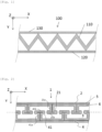
- FIG. 1 to 10 represent part of these elements in section along the XY plane in order to illustrate different examples of reinforcement elements.
- the ends of the elements are not shown: when printing, the ends form, for example, a return along the Y axis connecting the two walls. As previously indicated, these ends can in certain cases be cut off, and therefore no longer be present in the final wall element.
- the reinforcing elements extend linearly, in the plane of the walls, along the Z axis (normal to the plane of the layers).
- the reinforcing elements are cylinders with generator Z.
- the position and shape of a reinforcing element along the X axis does not depend on the height along the Z axis.
- the additive manufacturing technique allows for slightly different designs: for example, the reinforcing elements can extend only over part of the height of the walls (along the Z axis) and/or the position of the reinforcing elements along the X axis or the shape of the reinforcing elements can depend on the height along the Z axis.
- the reinforcement elements are arranged periodically. However, it is possible to proceed differently, the additive manufacturing method being able to produce the most varied and complex geometries.
- the width of the complete wall element, along the X axis, is for example between 1 and 3 m.
- the height of the wall element, along the Z axis, is for example between 1 and 3 m.
- the thickness of the wall element, along the Y axis is for example between 20 and 100 cm, in particular between 30 and 80 cm.
- FIG. 1 illustrates a portion of a wall element 100 according to the prior art, which comprises a single reinforcing element 110 along a broken line forming angles alternately protruding and retracting and connecting the two walls 120 and 130.
- the manufacture of this type of wall element is generally carried out by printing, for a given layer, first the walls 120 and 130 (as well as the lateral edges not shown) then the reinforcing element 110 and repeating this step.
- the patent KR 10-1911404 describes a variant of this type of wall, in which this structure is doubled, the wall then comprising three walls and two zigzag reinforcing elements each connecting two opposing walls.
- FIG. 2 represents a part of a wall element 1 according to one embodiment of the invention.
- This element comprises a first wall 2 and a second wall 4 forming a cavity 3.
- the section of each wall in an XY cutting plane is formed by two adjacent mortar strips, an outer strip 5 and an inner strip 6.
- the printer moves in the XY plane and can for example first print the outer strip 5 (including the ends not shown), which forms the external contour of the wall element, then, within the area defined by the outer strip 5, the inner strip 6.
- This inner strip 6 comprises parts extending along the X axis, which together form part of the wall, and parts which extend from the walls in the Y direction, in other words the reinforcing elements.
- the wall element comprises a plurality of reinforcing elements 21, 41 each having a T-shaped profile and extending from one of the walls 2, 4, towards the cavity 3.
- Each reinforcing element comprises a first linear portion 21a, 41a extending from a wall 2, 4 in the YZ plane (orthogonal to the plane of the walls) as well as a second linear portion 21b, 41b extending from the first portion 21a, 41a in the XZ plane, therefore in a plane parallel to the plane of the walls.
- the plurality of reinforcing elements comprises a first plurality of reinforcing elements 21 extending from the first wall 2 and a second plurality of reinforcing elements 41 extending from the second wall 4.
- the reinforcing elements are arranged alternately, each reinforcing element of one of the first and second plurality being directly framed by two reinforcing elements of the other plurality.
- the transverse branches of the Ts are all in the same plane, here the median plane of the two walls, shown diagrammatically by a dotted line.
- the reinforcing elements are in contact only with the wall from which they extend. As shown in the figure, they are not in contact with the other wall or any other reinforcing element.
- FIG. 3 represents a variant, in which the transverse branches of the T are in two different planes, parallel to the planes of the walls. More precisely, the transverse branches of the reinforcing elements 21b, 41b of the first (21), respectively second (41), plurality of reinforcing elements are in a first plane, respectively second plane, parallel to the plane of the walls.
- FIG. 4 represents yet another variant, in which the transverse branches of the Ts (21b and 41b) are elongated, so that the transverse branches 21b of the first reinforcing elements 21 are partially opposite the branches 41b of the adjacent second reinforcing elements 41.
- FIG. 5 illustrates another variant, in which the reinforcing elements 21 and 41 have an L-shaped profile.
- Each reinforcing element therefore comprises a first part (21a, 41a) and a second part (21b, 41b), the second part forming a return of the first part.
- FIG. 6 represents a variant in which the reinforcing elements 21 and 41 form linear wings projecting from the walls.
- Each reinforcing element here comprises only a first linear part (21a, 41a), in other words has an I-shaped profile.
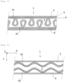
- each reinforcing element 22 and 42 forms a curve closed on itself at the level of the wall from which it extends, thereby delimiting a cell.
- the reinforcing elements are arranged alternately, each reinforcing element of one of the first and second plurality being directly framed by two reinforcing elements of the other plurality.
- FIG. 8 illustrates another embodiment in which the wall element comprises only two reinforcing elements, a first reinforcing element 22 arranged along the first wall 2, and a second reinforcing element 42 arranged along the second wall 4.
- the first reinforcing element 22 forms a periodic pattern, here sinusoidal, facing the second reinforcing element 42.
- FIG. 9 illustrates a variant of the embodiment of the figure 8 , in which the two periodic patterns are offset by half a period.
- the printer can for example, in the XY plane, first print walls 2 and 4, which form the external contour of the wall element, then, inside the area defined by these walls, the reinforcing elements 22 and 42.
- FIG. 10 illustrates a variant in which the reinforcing elements 21 and 41 consist of a succession of broken lines.
- the equivalent thermal conductivity was 200 mW.m -1 .K -1 with a polyurethane foam filling and 220 mW.m- 1 .K -1 with a glass wool filling.
- the equivalent thermal conductivity was respectively 100 mW.m -1 .K -1 and 140 mW.m -1 .K -1 .
Landscapes
- Engineering & Computer Science (AREA)
- Chemical & Material Sciences (AREA)
- Ceramic Engineering (AREA)
- Structural Engineering (AREA)
- Architecture (AREA)
- Materials Engineering (AREA)
- Mechanical Engineering (AREA)
- Manufacturing & Machinery (AREA)
- Civil Engineering (AREA)
- Organic Chemistry (AREA)
- Inorganic Chemistry (AREA)
- Chemical Kinetics & Catalysis (AREA)
- Physics & Mathematics (AREA)
- Electromagnetism (AREA)
- Acoustics & Sound (AREA)
- Producing Shaped Articles From Materials (AREA)
- Building Environments (AREA)
- Curing Cements, Concrete, And Artificial Stone (AREA)
- Foundations (AREA)
- Finishing Walls (AREA)
Description
- L'invention se rapporte au domaine de la construction. Elle concerne plus particulièrement la fabrication d'éléments de construction en béton par une technique de fabrication additive.
- Egalement appelée « impression 3D », la fabrication additive est une méthode dans laquelle un robot contrôlé par ordinateur fabrique des objets tridimensionnels en déposant de manière continue un matériau couche après couche. Ces techniques permettent en particulier de fabriquer des objets présentant des formes complexes.
- La fabrication additive d'éléments en béton ou mortier permet d'intégrer les processus de conception, de planification et de construction et d'automatiser et rationaliser ce dernier. D'autres avantages de cette technologie sont notamment une réduction du coût de main d'œuvre, une réduction des pertes et de la consommation en matériau, la suppression des coffrages et la réduction de la durée des projets et des investissements.
- Dans le présent texte on entend indifféremment par béton ou mortier un matériau comprenant un liant hydraulique et des granulats. Dans les technologies connues, un mortier humide, obtenu en mélangeant un mortier sec et de l'eau de gâchage, est pompé et convoyé vers une tête d'impression solidaire d'un robot ou d'un portique dont le mouvement est contrôlé par ordinateur. Une couche de mortier humide est déposée sur une couche de mortier précédemment déposée, généralement en étant extrudée au travers d'une buse. La tête d'impression est continûment déplacée selon un schéma prédéterminé afin de fabriquer l'objet final.
- La fabrication additive a par exemple été employée pour fabriquer des murs en béton en imprimant des parois planes opposées et parallèles entre elles et, à l'intérieur de la cavité ménagée par ces parois, une structure « en zigzag », donc selon une ligne brisée formant des angles alternativement saillants et rentrants, reliant ces deux parois. La structure délimite ainsi une pluralité de cavités séparées les unes des autres par une épaisseur de béton. Le brevet
KR 10-1911404 FR3029811 - L'invention vise à fabriquer des éléments de construction sous forme d'un mur, d'un élément de mur ou d'un élément de plancher, présentant à la fois une bonne résistance mécanique, notamment en compression, en flexion et en cisaillement, et de bonnes performances en termes d'isolation thermique.
- A cet effet l'invention a pour objet un procédé d'obtention d'un élément de construction en béton par fabrication additive, dans lequel on dépose successivement des couches de mortier superposées de manière à former deux parois, opposées l'une à l'autre de façon à ménager une cavité, ainsi qu'une pluralité d'éléments de renfort s'étendant chacun depuis l'une des parois vers la cavité, chaque élément de renfort n'étant en contact ni avec la paroi opposée à celle depuis laquelle il s'étend ni avec un élément de renfort s'étendant depuis la paroi opposée à celle depuis laquelle il s'étend, ledit élément de construction étant un mur, un élément de mur ou un élément de plancher.
- L'invention a aussi par objet un élément de construction en béton obtenu selon le procédé de l'invention, comprenant deux parois opposées l'une à l'autre de façon à ménager une cavité, ainsi qu'une pluralité d'éléments de renfort réalisés de matière avec lesdites parois et s'étendant chacun depuis l'une des parois vers la cavité, chaque élément de renfort n'étant en contact ni avec la paroi opposée à celle depuis laquelle il s'étend ni avec un élément de renfort s'étendant depuis la paroi opposée à celle depuis laquelle il s'étend, ledit élément de construction étant un mur, un élément de mur ou un élément de plancher.
- L'élément de construction est un mur, un élément de mur, en particulier pour un mur de façade ou de refend, ou un élément de plancher. L'élément sera généralement destiné à être intégré à la structure d'un bâtiment.
- Le dépôt successif de couches de mortier superposées est réalisé de manière à former deux parois et une pluralité d'éléments de renfort. Les éléments de renfort, imprimés avec les parois et donc de matière avec elles, permettent de conférer une bonne résistance mécanique à l'élément de construction ainsi fabriqué. L'élément de construction est de préférence constitué de deux parois opposées et des éléments de renfort, et éventuellement d'un matériau isolant remplissant la cavité.
- Dans les murs connus, la structure en zigzag permet également de renforcer le mur, mais il apparaît que cette structure crée des ponts thermiques défavorables entre les parois opposées qu'elle relie. Dans le brevet
KR 10-1911404 - Chaque élément de renfort n'est de préférence en contact qu'avec la paroi depuis laquelle il s'étend. Comme expliqué dans la suite du texte, on n'exclut toutefois pas que les éléments de renfort soient en contact avec un éventuel matériau isolant remplissant la cavité. Un élément de renfort peut aussi être en contact avec un autre élément de renfort qui s'étendrait depuis la même paroi que lui. Dans le présent texte on entend par contact un contact direct.
- Contrairement aux murs connus, dans lesquels la structure en zigzag délimite une pluralité de cavités séparées, les éléments de renfort de l'élément de construction selon l'invention sont généralement tels que l'élément de construction ne comprend qu'une unique cavité. Comme indiqué dans la suite du texte, cette cavité peut être remplie par un matériau isolant. La présence d'une seule cavité, outre l'avantage qu'elle procure en termes d'isolation thermique, permet de faciliter le processus de remplissage.
- La cavité est normalement telle que l'on peut y tracer une ligne traversant l'ensemble de l'élément de construction dans un plan horizontal (l'élément étant positionné tel qu'il a été imprimé) et dans la direction générale des parois sans traverser de couche de mortier.
- De préférence, les parois sont planes et parallèles entre elles. Alternativement, les parois peuvent présenter toutes formes, comme des formes courbes ou encore des lignes brisées.
- Les parois présentent de préférence une forme rectangulaire, ayant par conséquent une largeur et une longueur. D'autres formes sont toutefois possibles.
- Généralement, du fait de l'emploi de la technique de fabrication additive, qui exige le dépôt de couches superposées, au moins un, notamment chaque, élément de renfort s'étend, dans le plan de la paroi, linéairement et selon une dimension de la paroi. Le plus souvent, chaque élément de renfort présente un profil s'étendant sensiblement selon l'axe normal au plan des couches de mortier. Dans le cas de parois rectangulaires, au moins un, notamment chaque, élément de renfort peut s'étendre, dans le plan de la paroi, selon la largeur ou selon la longueur des parois. Dans son utilisation finale, l'élément de mur peut être placé de sorte que sa largeur ou sa longueur soit disposée verticalement, de sorte que les éléments de renfort pourront s'étendre verticalement ou horizontalement.
- La forme et la répartition des éléments de renfort influent sur la résistance mécanique et les propriétés d'isolation thermique de l'élément de construction obtenu.
- De préférence, chaque élément de renfort possède une forme identique. Alternativement, l'élément de construction peut comprendre des éléments de renfort ayant des formes différentes.
- Les éléments de renfort peuvent être disposés périodiquement ou non.
- Selon un mode de réalisation avantageux, au moins un, notamment chaque, élément de renfort comprend une première partie s'étendant linéairement depuis l'une des parois et transversalement auxdites parois. L'angle α formé par cette première partie et par la paroi est de préférence compris entre 75 et 105°, notamment entre 80 et 100°, voire entre 85 et 95°. Cet angle est avantageusement un angle droit. Lorsque la paroi n'est pas plane, l'angle peut être mesuré en prenant en compte le plan tangent à la paroi dans la zone à partir de laquelle l'élément s'étend.
- Dans la direction d'extension de la première partie (transversalement aux parois), le rapport entre la longueur de cette première partie et la distance entre les parois est de préférence compris entre 0,2 et 0,8, notamment entre 0,3 et 0,7.
- Selon ce mode, au moins un, notamment chaque, élément de renfort peut former une aile en saillie par rapport à la paroi depuis laquelle il s'étend. L'aile peut notamment présenter un profil rectangulaire.
- Au moins un, notamment chaque élément de renfort, peut comprendre en outre une deuxième partie linéaire s'étendant depuis la première partie et transversalement à celle-ci. L'élément de renfort peut par exemple présenter un profil en T ou en L. Le rapport entre la longueur de cette deuxième partie et la distance entre les parois est de préférence compris entre 0,1 et 0,7, notamment entre 0,2 et 0,6. Par « transversalement » on n'entend pas nécessairement l'angle entre la première et la deuxième partie est un angle droit. L'angle β entre la première et la deuxième partie est de préférence compris entre 70 et 110°, notamment entre 80 et 100°. Il peut être un angle droit, comme dans le cas d'éléments ayant un profil en L ou en T.
- Selon un autre mode de réalisation, au moins un, notamment chaque, élément de renfort forme une courbe refermée, notamment sur elle-même, au niveau d'une des parois, délimitant au moins une alvéole. Dans ce cas, l'élément de mur comporte plusieurs cavités : la cavité unique délimitée par les parois et les alvéoles situées à l'intérieur des éléments de renfort.
- De préférence, afin d'optimiser la résistance mécanique de l'élément de construction, et ce quelle que soit la forme des éléments de renfort, deux éléments de renfort consécutifs s'étendent à partir de deux parois différentes. L'élément de construction comprend alors une pluralité d'éléments de renfort s'étendant en alternance depuis chacune des parois.
- Dans le plan d'une des parois, le rapport entre la distance entre deux éléments de renfort consécutifs s'étendant depuis la paroi concernée et la distance entre les parois est de préférence compris entre 0,5 et 10, notamment entre 2 et 8.
- Afin d'assurer un bon compromis entre la thermique et la mécanique, le nombre d'élément de renfort par mètre linéaire d'élément de construction est de préférence compris entre 1 et 5, notamment entre 1 et 4, voire entre 2 et 3 (bornes comprises).
- Selon un autre mode de réalisation, l'élément de construction comprend deux éléments de renfort disposés chacun le long d'une des parois, et de préférence sur toute la longueur desdites parois, et formant un motif périodique, par exemple sinusoïdal ou en lignes brisées, délimitant ainsi une pluralité d'alvéoles.
- En coupe dans un plan transversal aux parois, autrement dit dans le plan des couches de mortier, l'épaisseur des parois est de préférence comprise entre 10 et 200 mm, notamment entre 40 et 120 mm. L'épaisseur des éléments de structure est de préférence comprise entre 20 et 100 cm, notamment entre 30 et 80 cm.
- Les dimensions latérales de l'élément de construction sont de préférence comprises entre 1 et 4 m, notamment entre 1 et 3 m.
- Le mortier comprend de préférence un liant hydraulique et des granulats.
- Le mortier humide, de consistance pâteuse, est formé par gâchage avec de l'eau d'un mortier sec. Par mortier sec on entend un mélange pulvérulent. Après prise et durcissement, le mortier final est appelé mortier durci, ou encore « béton ».
- Le liant hydraulique est de préférence choisi parmi les ciments Portland, les ciments alumineux, les ciments sulfoalumineux, la chaux hydratée, les laitiers de haut fourneau granulés broyés, les cendres volantes et leurs mélanges. Le liant hydraulique comprend de préférence un ciment Portland. Il est avantageusement constitué de ciment Portland.
- Les granulats sont de préférence choisis parmi les granulats siliceux, calcaires, dolomitiques et les mélanges de ces derniers. La taille maximale des granulats est de préférence d'au plus 3 mm, notamment d'au plus 2 mm et même d'au plus 1 mm, compte tenu de la section réduite du dispositif de pompage et de la buse de la tête d'impression.
- Le mortier sec comprend de préférence au moins un additif, notamment choisi parmi les superplastifiants, les épaississants, les accélérateurs et les retardateurs. Le mortier sec comprend avantageusement des épaississants inorganiques, par exemple des argiles gonflantes, capables d'augmenter la limite d'élasticité au repos du mortier humide. Les accélérateurs et retardateurs permettent d'ajuster le temps nécessaire à la prise et au durcissement du liant hydraulique.
- La composition du mortier sec est de préférence ajustée de sorte que le mortier humide présente un comportement thixotrope. De préférence, la viscosité du mortier humide augmente d'un facteur d'au moins 50 seulement une seconde après que le mortier humide a quitté la buse d'impression. Le mortier humide présente alors une faible viscosité pour de forts taux de cisaillement de sorte qu'il peut être facilement pompé et convoyé, mais présente une augmentation immédiate de sa stabilité structurelle dès qu'il quitte la buse de la tête d'impression, permettant ainsi de supporter les couches sus-jacentes avant prise et durcissement. Ce dépôt sur couche de mortier encore humide permet d'améliorer l'adhésion entre les couches successives, et donc la résistance mécanique finale de l'élément de mur. Par contraste, les procédés habituels utilisent des accélérateurs permettant d'accélérer fortement la prise et le durcissement du mortier de manière à déposer sur des couches d'un mortier qui a déjà pris ou durci, ce qui permet d'assurer une stabilité dimensionnelle pendant l'impression mais au détriment de l'adhésion entre les couches successives.
- Le procédé comprend le dépôt successif de couches de mortier superposées. Comme indiqué précédemment, les couches sont de préférence déposées sur une couche sous-jacente qui n'a pas encore pris ou n'a pas encore durci.
- Le procédé comprend de préférence une étape de mélange d'une composition de mortier sec avec de l'eau afin d'obtenir un mortier humide, de consistance pâteuse. Le mortier humide est de préférence pompé et acheminé, généralement dans un tuyau, vers la tête d'impression d'une imprimante. La tête d'impression comprend notamment une buse à travers laquelle le mortier humide est extrudé. L'imprimante est par exemple un robot industriel ou un portique, portant la tête d'impression, et dont le mouvement est piloté par un ordinateur. L'ordinateur comprend notamment un support d'enregistrement dans lequel est stocké un ensemble de données ou modèle 3D ainsi que des instructions, qui lorsqu'elles sont exécutées par l'ordinateur conduisent ce dernier à contrôler le déplacement (trajectoire, vitesse...) de la tête d'impression.
- La vitesse d'impression est typiquement de 30 à 1000 mm/s, notamment de 50 à 300 mm/s. L'épaisseur (ou hauteur, puisqu'il s'agit ici de la dimension dans la direction verticale) des couches de mortier humide est de préférence comprise entre 5 et 40 mm, notamment entre 10 et 20 mm. La largeur des couches de mortier est de préférence comprise entre 10 et 100 mm, notamment entre 20 et 60 mm.
- Comme expliqué plus en détail dans la suite du texte, pour chaque couche l'imprimante peut déposer d'abord une bande de mortier, appelée bande externe, formant l'enveloppe extérieure de l'élément de mur, puis une bande interne adjacente à la bande externe et en contact avec elle, qui comporte des portions parallèles à la bande externe, formant avec cette dernière les parois, et des portions s'étendant vers la cavité, formant les éléments de renfort.
- De préférence, le procédé comprend en outre une étape de remplissage de la cavité (ou d'au moins une partie de la cavité) par un matériau isolant. Dans le cas où les éléments de renfort délimitent des alvéoles, ces dernières peuvent également être remplies par le matériau isolant, lors de la même étape ou d'une étape ultérieure.
- Le matériau isolant peut par exemple être minéral ou organique.
- Le matériau isolant est avantageusement choisi parmi les mousses minérales, les mousses organiques, les laines minérales, les mortiers comprenant un liant minéral et des granulats légers et les isolants à base de matériaux naturels, notamment à base de fibres naturelles (végétales ou animales).
- Le procédé de remplissage est adapté en fonction du matériau choisi et peut mettre en oeuvre selon les cas l'écoulement, l'injection ou encore la projection d'un matériau pâteux ou granulaire, ou la projection de composés précurseurs du matériau, lequel se forme in situ à l'intérieur de la cavité. Le procédé de remplissage peut être mis en oeuvre par un robot, le cas échéant par le même robot que celui qui réalise l'impression 3D.
- Les mousses minérales sont notamment des mousses de silice ou des mousses à base de liant hydraulique, par exemple des mousses de ciment, de mortier ou de béton. Ces dernières peuvent notamment être obtenues par mélange de mortier ou béton humide avec une mousse aqueuse. Dans un tel cas, l'étape de remplissage met de préférence en oeuvre l'écoulement de la mousse minérale à l'état pâteux à l'intérieur de la cavité. La mousse peut ensuite durcir à l'intérieur de la cavité. L'étape de remplissage peut être réalisée avant durcissement de l'élément de mur, notamment simultanément avec la fabrication de l'élément de mur, ou après durcissement de l'élément de mur. Après durcissement, la mousse minérale présente de préférence une masse volumique inférieure à 200 kg/m3, notamment inférieure à 150 kg/m3, voire même inférieure à 100 kg/m3. La mousse de béton peut notamment être la mousse commercialisée sous la référence Airium par la société LafargeHolcim.
- Les mousses organiques sont par exemple des mousses de polyuréthane ou de polyisocyanurate. De telles mousses peuvent être formées in situ à l'intérieur de la cavité, l'étape de remplissage mettant alors en oeuvre la projection simultanée d'un composé isocyanate et d'un alcool à l'intérieur de la cavité.
- Les laines minérales sont notamment des laines de verre, des laines de roche ou encore des laines de laitier. Il peut notamment s'agir de laines à souffler (ou laines en vrac), c'est-à-dire se présentant sous forme de flocons. Dans ce cas, l'étape de remplissage met en oeuvre la projection desdits flocons à l'intérieur de la cavité. Les laines minérales peuvent être combinées avec un liant hydraulique, notamment cimentaire.
- Les mortiers comprenant un liant minéral et des granulats légers permettent également de conférer des propriétés isolantes. Le liant minéral est de préférence un liant hydraulique, par exemple un ciment Portland. Les granulats légers présentent de préférence une masse volumique d'au plus 200 kg/m3. Les granulats légers sont de préférence choisis parmi les billes de polystyrène expansé, les aérogels, la perlite, les billes de verre expansé, la vermiculite, les argiles expansées, le liège et les cénosphères.
- Les isolants à base de matériaux naturels sont notamment à base de matériaux cellulosiques (liège, fibres de bois, fibres de cellulose...) ou à base de laines animales (laine de mouton...) .
- Quel que soit le procédé employé, la présence d'une unique cavité peut simplifier l'étape de remplissage, permettant par exemple le recours à une seule buse de remplissage éventuellement fixe plutôt que de devoir utiliser soit une buse par cavité soit une buse mobile devant être déplacée pour remplir successivement les cavités.
- Lorsqu'il présente une adhésion avec le mortier constituant les parois et les éléments de renfort, le matériau isolant peut jouer un rôle structurel et ainsi améliorer les propriétés mécaniques de l'élément de construction. C'est le cas par exemple lorsque le matériau isolant comprend un liant minéral, notamment hydraulique. Le procédé selon l'invention peut alors comprendre une étape de découpe des extrémités latérales de l'élément. On peut ainsi enlever les bords en béton formés lors de l'impression et améliorer les performances thermiques de l'élément de mur.
- L'élément de construction peut également comprendre des pièces de renfort qui ne sont pas de matière avec les parois et qui peuvent s'étendre entre ces parois. Ces pièces peuvent notamment être fixées mécaniquement aux parois après ou pendant la fabrication de l'élément de construction. Elles seront de préférence en matière polymérique afin de limiter les ponts thermiques.
- Les éléments de construction peuvent être des éléments préfabriqués, destinés à être assemblés sur le chantier de construction, par exemple au moyen d'un mortier, afin de former les murs extérieurs ou intérieurs (par exemple les murs de refend) d'un bâtiment. Les éléments peuvent aussi être fabriqués directement sur le chantier de construction et former le mur complet du bâtiment.
- L'invention et ses avantages seront mieux compris à l'aide de la description qui suit, en référence aux
figures 1 à 10 annexées, d'exemples non-limitatifs d'éléments de construction. Il s'agit en l'espèce d'éléments de mur. - Les éléments de mur exemplifiés ici sont des éléments parallélépipédiques rectangles comprenant deux parois planes parallèles entre elles s'étendant selon un plan XZ, aussi appelé « plan des parois ». On qualifie dans le présent texte de « plan des parois » tout plan parallèle au plan XZ. L'axe Y est l'axe orthogonal au plan des parois. L'axe Z est l'axe orthogonal au plan des couches (plan XY).
- Les
figures 1 à 10 représentent une partie de ces éléments en coupe selon le plan XY afin d'illustrer différentes exemples d'éléments de renfort. Les extrémités des éléments ne sont pas représentées : lors de l'impression les extrémités forment par exemple un retour selon l'axe Y reliant les deux parois. Comme indiqué précédemment, ces extrémités peuvent dans certains cas être découpées, et donc ne plus être présentes dans l'élément de mur final. - Dans tous les cas représentés, les éléments de renfort s'étendent linéairement, dans le plan des parois, selon l'axe Z (normal au plan des couches). Autrement dit, les éléments de renfort sont des cylindres de génératrice Z. La position et la forme d'un élément de renfort selon l'axe X ne dépend pas de la hauteur selon l'axe Z. La technique de fabrication additive autorise toutefois des conceptions légèrement différentes : les éléments de renfort peuvent par exemple ne s'étendre que sur une partie de la hauteur des parois (selon l'axe Z) et/ou la position des éléments de renfort selon l'axe X ou la forme des éléments de renfort peut dépendre de la hauteur selon l'axe Z.
- Dans tous les cas représentés, les éléments de renfort sont disposés de manière périodique. Il est toutefois possible de procéder autrement, la méthode de fabrication additive étant à même de réaliser les géométries les plus variées et les plus complexes.
- La largeur de l'élément de mur complet, selon l'axe X, est par exemple comprise entre 1 et 3 m. La hauteur de l'élément de mur, selon l'axe Z, est par exemple comprise entre 1 et 3 m. L'épaisseur de l'élément de mur, selon l'axe Y, est par exemple comprise entre 20 et 100 cm, notamment entre 30 et 80 cm.
- [
Fig. 1 ] illustre une partie d'un élément de mur 100 selon l'art antérieur, qui comprend un seul élément de renfort 110 selon une ligne brisée formant des angles alternativement saillants et rentrants et reliant les deux parois 120 et 130. La fabrication de ce type d'élément de mur est généralement réalisée en imprimant, pour une couche donnée, d'abord les parois 120 et 130 (ainsi que les bords latéraux non représentés) puis l'élément de renfort 110 et en répétant cette étape. Le brevetKR 10-1911404 - [
Fig. 2 ] représente une partie d'un élément de mur 1 selon un mode de réalisation de l'invention. - Cet élément comprend une première paroi 2 et une deuxième paroi 4 ménageant une cavité 3. Dans l'exemple illustré, la section de chaque paroi dans un plan de coupe XY est formée par deux bandes de mortiers adjacentes, une bande extérieure 5 et une bande intérieure 6. Pour une couche donnée (un niveau donné selon l'axe Z), l'imprimante se déplace dans le plan XY et peut par exemple d'abord imprimer la bande extérieure 5 (y compris les extrémités non représentées), qui forme le contour externe de l'élément de mur, puis, à l'intérieur de la zone définie par la bande extérieure 5, la bande intérieure 6. Cette bande intérieure 6 comprend des parties s'étendant selon l'axe X, qui ensemble font partie de la paroi, et des parties qui s'étendent depuis les parois dans la direction Y, autrement dit les éléments de renfort.
- L'élément de mur comprend une pluralité d'éléments de renfort 21, 41 présentant chacun un profil en T et s'étendant depuis l'une des parois 2, 4, vers la cavité 3. Chaque élément de renfort comprend une première partie linéaire 21a, 41a s'étendant depuis une paroi 2, 4 dans le plan YZ (orthogonal au plan des parois) ainsi qu'une deuxième partie linéaire 21b, 41b s'étendant depuis la première partie 21a, 41a dans le plan XZ, donc dans un plan parallèle au plan des parois.
- La pluralité d'éléments de renfort comprend une première pluralité d'éléments de renfort 21 s'étendant à partir de la première paroi 2 et une deuxième pluralité d'éléments de renfort 41 s'étendant à partir de la deuxième paroi 4. Les éléments de renfort sont disposés en alternance, chaque élément de renfort d'une parmi la première et la deuxième pluralité étant directement encadré par deux éléments de renfort de l'autre pluralité.
- Dans l'exemple représenté, les branches transversales des T (deuxièmes parties 21b et 41b) sont toutes dans un même plan, ici le plan médian des deux parois, schématisé par un trait en pointillé.
- Les éléments de renfort ne sont en contact qu'avec la paroi depuis laquelle ils s'étendent. Comme illustré sur la figure, ils ne sont en contact ni avec l'autre paroi, ni avec aucun autre élément de renfort.
- [
Fig .3 ] représente une variante, dans laquelle les branches transversales des T sont dans deux plans différents, parallèles aux plans des parois. Plus précisément, les branches transversales des éléments de renfort 21b, 41b de la première (21), respectivement deuxième (41), pluralité d'éléments de renfort sont dans un premier plan, respectivement deuxième plan, parallèle au plan des parois. - [
Fig. 4 ] représente encore une autre variante, dans laquelle les branches transversales des T (21b et 41b) sont allongées, de sorte que les branches transversales 21b des premiers éléments de renfort 21 sont partiellement en regard des branches 41b des deuxièmes éléments de renfort 41 adjacents. - [
Fig. 5 ] illustre une autre variante, dans laquelle les éléments de renfort 21 et 41 présentent un profil en L. Chaque élément de renfort comprend donc une première partie (21a, 41a) et une deuxième partie (21b, 41b), la deuxième partie formant un retour de la première partie. - [
Fig. 6 ] représente une variante dans laquelle les éléments de renfort 21 et 41 forment des ailes linéaires en saillie depuis les parois. Chaque élément de renfort ne comprend ici qu'une première partie linéaire (21a, 41a), autrement dit présente un profil en I. - [
Fig. 7 ] représente une variante dans laquelle chaque élément de renfort 22 et 42 forme une courbe refermée sur elle-même au niveau de la paroi à partir de laquelle il s'étend, délimitant de ce fait une alvéole. - Dans les différentes variantes présentées, les éléments de renfort sont disposés en alternance, chaque élément de renfort d'une parmi la première et la deuxième pluralité étant directement encadré par deux éléments de renfort de l'autre pluralité.
- [
Fig. 8 ] illustre un autre mode de réalisation dans lequel l'élément de mur ne comprend que deux éléments de renfort, un premier élément de renfort 22 disposé le long de la première paroi 2, et un deuxième élément de renfort 42 disposé le long de la deuxième paroi 4. Le premier élément de renfort 22 forme un motif périodique, ici sinusoïdal, faisant face au deuxième élément de renfort 42. - [
Fig. 9 ] illustre une variante du mode de réalisation de lafigure 8 , dans laquelle les deux motifs périodiques sont décalés d'une demi-période. - Dans le mode de réalisation des
figures 8 et9 , l'imprimante peut par exemple, dans le plan XY, d'abord imprimer les parois 2 et 4, qui forment le contour externe de l'élément de mur, puis, à l'intérieur de la zone définie par ces parois, les éléments de renfort 22 et 42. - [
Fig. 10 ] illustre une variante dans laquelle les éléments de renfort 21 et 41 sont constitués d'une succession de lignes brisées. - Des simulations numériques ont permis de comparer la conductivité thermique équivalente d'éléments de mur selon l'invention (géométrie du type de celle représentée en
figure 2 ) avec celle d'un élément de mur selon l'art antérieur (géométrie en zigzag, du type de celle représentée enfigure 1 ). Selon les cas les cavités étaient remplies avec une mousse de polyuréthane (conductivité thermique de 22 mW.m-1.K-1) ou avec de la laine de verre (conductivité thermique de 35 mW.m-1.K-1). Le mortier durci possède quant à lui une conductivité thermique de 750 mW.m-1.K-1. - Dans le cas du mur selon l'art antérieur, la conductivité thermique équivalente était de 200 mW.m-1.K-1 avec un remplissage en mousse de polyuréthane et de 220 mW.m-1.K-1 avec un remplissage en laine de verre.
- Dans le cas du mur selon l'invention, la conductivité thermique équivalente était respectivement de 100 mW.m-1.K-1 et 140 mW.m-1.K-1.
Claims (16)
- Procédé d'obtention d'un élément de construction en béton (1) par fabrication additive, dans lequel on dépose successivement des couches de mortier superposées de manière à former deux parois (2, 4), opposées l'une à l'autre de façon à ménager une cavité (3), ainsi qu'une pluralité d'éléments de renfort (21, 41, 22, 42) s'étendant chacun depuis l'une des parois (2, 4) vers la cavité (3), ledit élément de construction étant un mur, un élément de mur ou un élément de plancher, caractérisé en ce que chaque élément de renfort n'est en contact ni avec la paroi opposée à celle depuis laquelle il s'étend ni avec un élément de renfort s'étendant depuis la paroi opposée à celle depuis laquelle il s'étend.
- Procédé selon la revendication 1, dans lequel au moins un élément de renfort (21, 41) comprend une première partie (21a, 41a) s'étendant linéairement depuis l'une des parois et transversalement auxdites parois (2, 4).
- Procédé selon la revendication précédente, dans lequel au moins un élément de renfort (21, 41) comprend en outre une deuxième partie linéaire (21b, 41b) s'étendant depuis la première partie (21a, 41a) et transversalement à celle-ci.
- Procédé selon la revendication précédente, dans lequel au moins un élément de renfort (21, 41) présente un profil en T ou en L.
- Procédé selon la revendication 1, dans lequel chaque élément de renfort (21, 41) forme une courbe refermée au niveau d'une des parois, délimitant au moins une alvéole.
- Procédé selon la revendication précédente, dans lequel la courbe est refermée sur elle-même.
- Procédé selon l'une des revendications précédentes, dans lequel deux éléments de renfort (21, 41) consécutifs s'étendent à partir de deux parois différentes (2, 4).
- Procédé selon la revendication précédente, tel que dans le plan d'une paroi (21, 41), le rapport entre la distance entre deux éléments de renfort consécutifs (21, 41) s'étendant depuis cette paroi et la distance entre les parois (2, 4) est de préférence compris entre 0,5 et 10, notamment entre 2 et 8.
- Procédé selon l'une des revendications 7 ou 8, tel que le nombre d'élément de renfort par mètre linéaire d'élément de construction est compris entre 1 et 5, notamment entre 1 et 4.
- Procédé selon l'une des revendications précédentes, comprenant en outre une étape de remplissage de la cavité par un matériau isolant.
- Procédé selon la revendication précédente, dans lequel le matériau isolant est choisi parmi les mousses minérales, les mousses organiques, les laines minérales, les mortiers comprenant un liant minéral et des granulats légers et les isolants à base de matériaux naturels.
- Procédé selon l'une des revendications précédentes, tel que chaque élément de renfort (21, 41, 22, 42) n'est en contact qu'avec la paroi (2, 4) depuis laquelle il s'étend, et le cas échéant avec un matériau isolant remplissant la cavité (3).
- Procédé selon l'une des revendications précédentes, tel que l'élément de construction (1) ne comprend qu'une unique cavité (3).
- Procédé selon l'une des revendications 1,10 ou 11, tel que l'élément de construction (1) comprend deux éléments de renfort (22, 42) disposés chacun le long d'une des parois (2, 4) et formant un motif périodique, par exemple sinusoïdal ou en lignes brisées, délimitant ainsi une pluralité d'alvéoles.
- Elément de construction en béton (1) obtenu selon le procédé de l'une des revendications précédentes, comprenant deux parois (2, 4), opposées l'une à l'autre de façon à ménager une cavité (3), ainsi qu'une pluralité d'éléments de renfort (21, 41, 22, 42) réalisés de matière avec lesdites parois (2, 4) et s'étendant chacun depuis l'une des parois (2, 4) vers la cavité (3), chaque élément de renfort (21, 41, 22, 42) n'étant en contact ni avec la paroi (2, 4) opposée à celle depuis laquelle il s'étend ni avec un élément de renfort (21, 41, 22, 42) s'étendant depuis la paroi opposée (2, 4) à celle depuis laquelle il s'étend, ledit élément de construction étant un mur, un élément de mur ou un élément de plancher.
- Elément de construction en béton (1) selon la revendication précédente, dont la cavité (3) est remplie par un matériau isolant.
Applications Claiming Priority (2)
| Application Number | Priority Date | Filing Date | Title |
|---|---|---|---|
| FR1911181A FR3101805B1 (fr) | 2019-10-09 | 2019-10-09 | Fabrication additive d’éléments de construction en béton |
| PCT/EP2020/078294 WO2021069601A1 (fr) | 2019-10-09 | 2020-10-08 | Fabrication additive d'elements de construction en beton |
Publications (3)
| Publication Number | Publication Date |
|---|---|
| EP4041509A1 EP4041509A1 (fr) | 2022-08-17 |
| EP4041509B1 true EP4041509B1 (fr) | 2025-01-15 |
| EP4041509C0 EP4041509C0 (fr) | 2025-01-15 |
Family
ID=69572079
Family Applications (1)
| Application Number | Title | Priority Date | Filing Date |
|---|---|---|---|
| EP20788787.8A Active EP4041509B1 (fr) | 2019-10-09 | 2020-10-08 | Fabrication additive d'elements de construction en beton |
Country Status (10)
| Country | Link |
|---|---|
| US (1) | US12385264B2 (fr) |
| EP (1) | EP4041509B1 (fr) |
| JP (1) | JP7566017B2 (fr) |
| CN (1) | CN114450455B (fr) |
| CA (1) | CA3151582A1 (fr) |
| ES (1) | ES3016746T3 (fr) |
| FR (1) | FR3101805B1 (fr) |
| IL (1) | IL291987A (fr) |
| SA (1) | SA522432186B1 (fr) |
| WO (1) | WO2021069601A1 (fr) |
Families Citing this family (8)
| Publication number | Priority date | Publication date | Assignee | Title |
|---|---|---|---|---|
| US11572692B2 (en) * | 2020-07-30 | 2023-02-07 | Icon Technology, Inc. | Extrudable building material wall structure and method |
| DE102021116194A1 (de) * | 2021-06-23 | 2022-12-29 | AEDITIVE GmbH | Verfahren und Fertigungssystem zur Herstellung eines Betonbauteils sowie Betonbauteil |
| EP4384672A1 (fr) * | 2021-08-13 | 2024-06-19 | Sika Technology AG | Panneau d'isolation thermique léger résistant au feu |
| JP7793945B2 (ja) * | 2021-11-08 | 2026-01-06 | 株式会社大林組 | 構造物及び構造物の形成方法 |
| JP2023147991A (ja) * | 2022-03-30 | 2023-10-13 | 太平洋セメント株式会社 | 付加製造装置用水硬性組成物 |
| DE102024109547A1 (de) * | 2024-04-05 | 2025-10-09 | FBL Fläming Baustoff-Labor GmbH | Verfahren zur herstellung eines schaumglashaltigen betonbauteils |
| WO2026021654A1 (fr) * | 2024-07-21 | 2026-01-29 | Karbachi Sidali | Bloc de maçonnerie à base d'une mousse minérale |
| CN119195381B (zh) * | 2024-11-29 | 2025-03-28 | 华侨大学 | 一种3d打印的剪力墙结构及施工方法 |
Family Cites Families (35)
| Publication number | Priority date | Publication date | Assignee | Title |
|---|---|---|---|---|
| CA267831A (fr) * | 1927-01-25 | Charles Matthews Alfred | Mur | |
| CH299286A (de) * | 1950-12-07 | 1954-06-15 | Becker Kurt | Bauelement. |
| GB2128225B (en) * | 1982-10-09 | 1986-03-19 | Peter Trevor Noon | Wall construction |
| US5209037A (en) * | 1989-11-09 | 1993-05-11 | Thermalock Products, Inc. | Building block insert |
| US5339592A (en) * | 1992-08-14 | 1994-08-23 | Schmid Donald T | Insulated building blocks and composite walls having stackable half-bond symmetry |
| WO2005070657A1 (fr) * | 2004-01-20 | 2005-08-04 | University Of Southern California | Construction automatisee comprenant des systemes robotiques |
| EP1744434B1 (fr) | 2004-05-06 | 2016-04-06 | Mitsubishi Denki K.K. | Procédé de fabrication d'un rotor d'une machine rotative électrique |
| US7930861B2 (en) * | 2006-12-04 | 2011-04-26 | Composite Panel Systems Llc | Building, building walls and other structures |
| CN101748816B (zh) * | 2009-12-28 | 2011-05-04 | 天津师范大学 | 免蒸加气混凝土复合外墙保温板及其生产方法 |
| BE1020097A5 (nl) * | 2010-10-08 | 2013-05-07 | Betaalbare Woning Nv De | Isolerende constructie voor de aanbouw van woningen en werkwijze hiervoor. |
| DE102010062061A1 (de) * | 2010-11-26 | 2012-05-31 | Wacker Chemie Ag | Bauelemente in Plattenform |
| EP2958736B1 (fr) * | 2013-02-21 | 2020-03-25 | Laing O'Rourke Australia Pty Limited | Procédé pour mouler un élément de construction |
| CN106794624B (zh) * | 2014-08-05 | 2020-03-03 | 莱茵奥洛克澳大利亚有限公司 | 用于制造物体的方法 |
| CN104453014B (zh) * | 2014-11-14 | 2017-04-05 | 中国建筑第八工程局有限公司 | 3d打印填充墙体与构造柱的连接方法和连接结构 |
| FR3029811B1 (fr) * | 2014-12-16 | 2019-04-12 | Xavier Rocher | Dispositif et procede de fabrication de structures tridimensionnelles realisees en couches successives |
| US10471665B1 (en) * | 2015-05-20 | 2019-11-12 | Marvell International Ltd. | Three dimensional (3D) printing with stitching of adjacent sub-walls |
| US11059217B2 (en) * | 2015-11-23 | 2021-07-13 | Frank A. McKiel, Jr. | Method and apparatus for transposing extruded materials to fabricate an object surface |
| CN205444560U (zh) * | 2016-03-22 | 2016-08-10 | 马义和 | 一种改进型3d打印的保温承重墙 |
| DE102016111047B3 (de) * | 2016-06-16 | 2017-10-26 | Brandenburgische Technische Universität Cottbus-Senftenberg | Verfahren und Anlage zur kombiniert additiven und umformenden Fertigung |
| US10074449B2 (en) * | 2016-06-21 | 2018-09-11 | Raytheon Company | Additively manufactured concrete-bearing radiation attenuation structure |
| CN206053005U (zh) * | 2016-08-25 | 2017-03-29 | 新疆天盛祥节能科技有限责任公司 | 预制薄抹灰复合保温板 |
| CN106760072A (zh) * | 2016-11-30 | 2017-05-31 | 盈创新材料(苏州)有限公司 | 一种3d打印墙体及其拼接方法 |
| KR101911404B1 (ko) * | 2017-01-19 | 2018-12-19 | 연세대학교 산학협력단 | 3d 프린팅 시스템을 위한 콘크리트 압출 장치 |
| FR3070302B1 (fr) * | 2017-08-24 | 2019-08-30 | Xtreee | Systeme d'extrusion de cordons de materiau de construction pour robot de fabrication additive de structures architecturales comprenant un dispositif d'insertion de fibres de renforcement |
| US10741159B2 (en) * | 2017-09-10 | 2020-08-11 | Douglas Peter Magyari | Acoustic-absorber system and method |
| JP6682126B2 (ja) | 2018-03-07 | 2020-04-15 | 雄太 平山 | 壁状構造物の構築方法 |
| JP7192301B2 (ja) * | 2018-08-13 | 2022-12-20 | 株式会社大林組 | 構造物及び構造物の形成方法 |
| US11066826B2 (en) * | 2018-08-21 | 2021-07-20 | John David Wright | Insulatable, insulative framework apparatus and methods of making and using same |
| KR102002829B1 (ko) * | 2018-11-27 | 2019-07-24 | 한국건설기술연구원 | 3d 프린터를 이용하여 제작한 벽체구조 |
| US11014295B2 (en) * | 2019-07-02 | 2021-05-25 | Saudi Arabian Oil Company | Fabrication of composite parts by additive manufacturing and microstructure topology optimization |
| US11014331B2 (en) * | 2019-08-05 | 2021-05-25 | Rohr, Inc. | Structured panel with non-parallel cavity walls |
| CN213926855U (zh) * | 2020-09-21 | 2021-08-10 | 上海言诺建筑材料有限公司 | 3d打印无冷桥墙体及房屋 |
| CN113323262A (zh) * | 2021-02-01 | 2021-08-31 | 长沙理工大学 | 一种3d打印的预制墙模块、墙体及其施工方法 |
| CN114102796B (zh) * | 2021-11-29 | 2024-01-26 | 河北工业大学 | 基于数值模拟的3d打印新型保温框架一体墙的制备方法 |
| CA3255469A1 (fr) * | 2022-03-30 | 2023-10-05 | Azure Printed Homes, Inc. | Structure imprimée en 3 dimensions, et système et procédé d'impression en 3 dimensions de structures |
-
2019
- 2019-10-09 FR FR1911181A patent/FR3101805B1/fr active Active
-
2020
- 2020-10-08 WO PCT/EP2020/078294 patent/WO2021069601A1/fr not_active Ceased
- 2020-10-08 CN CN202080070872.9A patent/CN114450455B/zh active Active
- 2020-10-08 IL IL291987A patent/IL291987A/en unknown
- 2020-10-08 CA CA3151582A patent/CA3151582A1/fr active Pending
- 2020-10-08 ES ES20788787T patent/ES3016746T3/es active Active
- 2020-10-08 JP JP2022521565A patent/JP7566017B2/ja active Active
- 2020-10-08 EP EP20788787.8A patent/EP4041509B1/fr active Active
- 2020-10-08 US US17/767,495 patent/US12385264B2/en active Active
-
2022
- 2022-04-06 SA SA522432186A patent/SA522432186B1/ar unknown
Also Published As
| Publication number | Publication date |
|---|---|
| FR3101805B1 (fr) | 2021-12-31 |
| FR3101805A1 (fr) | 2021-04-16 |
| CN114450455B (zh) | 2023-10-31 |
| WO2021069601A1 (fr) | 2021-04-15 |
| CA3151582A1 (fr) | 2021-04-15 |
| US20240076885A1 (en) | 2024-03-07 |
| ES3016746T3 (en) | 2025-05-09 |
| KR20220081334A (ko) | 2022-06-15 |
| JP2022551175A (ja) | 2022-12-07 |
| EP4041509C0 (fr) | 2025-01-15 |
| SA522432186B1 (ar) | 2024-03-26 |
| JP7566017B2 (ja) | 2024-10-11 |
| IL291987A (en) | 2022-06-01 |
| CN114450455A (zh) | 2022-05-06 |
| EP4041509A1 (fr) | 2022-08-17 |
| US12385264B2 (en) | 2025-08-12 |
Similar Documents
| Publication | Publication Date | Title |
|---|---|---|
| EP4041509A1 (fr) | Fabrication additive d'elements de construction en beton | |
| EP2295666B1 (fr) | Procédé de fabrication de panneaux avec isolation integrée et d'un tel panneau | |
| CH642338A5 (fr) | Composition hydrofuge en poudre a base de ciment, sa preparation et son utilisation. | |
| WO2017191404A1 (fr) | Procédé pour la construction d'un mur de bâtiment par fabrication additive | |
| FR3023859A1 (fr) | Element de construction isolant, procede de fabrication et materiau isolant correspondants | |
| CN105881703A (zh) | 一种陶瓷新型板材及其生产方法 | |
| FR2951206A1 (fr) | Panneau de construction composite | |
| EP4179171B1 (fr) | Fabrication additive d'élément de construction isolants | |
| CN213441448U (zh) | 一种耐腐蚀无胎基防水卷材 | |
| RU2166590C2 (ru) | Плоский ограждающий строительный элемент и способ его изготовления | |
| EP3559367A1 (fr) | Systeme d'isolation thermique par l'exterieur constitue d'un mortier projete fortement isolant et procede de fabrication du systeme | |
| WO2012055918A2 (fr) | Element de construction en terre crue | |
| CN209924259U (zh) | 一种装饰一体化复合围护墙板 | |
| FR2524921A1 (fr) | Nouvelle structure de paroi composite, procedes pour sa mise en oeuvre dans le domaine du batiment et elements de construction ainsi obtenus | |
| RU169086U1 (ru) | Плита изоляционная облицовочная | |
| KR102958704B1 (ko) | 콘크리트 건설 요소의 적층 제조 | |
| EP2473684B1 (fr) | Mur de bâtiment et procede pour realiser ce mur. | |
| CN101994363A (zh) | 多孔夹芯胶砂保温砌块及其制造方法 | |
| HK40070226A (en) | Additive manufacturing of concrete construction elements | |
| RU2318101C1 (ru) | Трехслойный строительный блок | |
| FR3137115A1 (fr) | Système de revêtement mural composite | |
| CN102277923A (zh) | 外墙保温砌块 | |
| CN204876209U (zh) | 一种用轻质陶粒石膏板作为免拆模板的现浇内隔墙 | |
| EP4402113A1 (fr) | Elément de construction isolant | |
| CN105888116A (zh) | 一种建筑砌砖 |
Legal Events
| Date | Code | Title | Description |
|---|---|---|---|
| STAA | Information on the status of an ep patent application or granted ep patent |
Free format text: STATUS: UNKNOWN |
|
| STAA | Information on the status of an ep patent application or granted ep patent |
Free format text: STATUS: THE INTERNATIONAL PUBLICATION HAS BEEN MADE |
|
| PUAI | Public reference made under article 153(3) epc to a published international application that has entered the european phase |
Free format text: ORIGINAL CODE: 0009012 |
|
| STAA | Information on the status of an ep patent application or granted ep patent |
Free format text: STATUS: REQUEST FOR EXAMINATION WAS MADE |
|
| 17P | Request for examination filed |
Effective date: 20220509 |
|
| AK | Designated contracting states |
Kind code of ref document: A1 Designated state(s): AL AT BE BG CH CY CZ DE DK EE ES FI FR GB GR HR HU IE IS IT LI LT LU LV MC MK MT NL NO PL PT RO RS SE SI SK SM TR |
|
| REG | Reference to a national code |
Ref country code: HK Ref legal event code: DE Ref document number: 40070226 Country of ref document: HK |
|
| DAV | Request for validation of the european patent (deleted) | ||
| DAX | Request for extension of the european patent (deleted) | ||
| STAA | Information on the status of an ep patent application or granted ep patent |
Free format text: STATUS: EXAMINATION IS IN PROGRESS |
|
| 17Q | First examination report despatched |
Effective date: 20231220 |
|
| GRAP | Despatch of communication of intention to grant a patent |
Free format text: ORIGINAL CODE: EPIDOSNIGR1 |
|
| STAA | Information on the status of an ep patent application or granted ep patent |
Free format text: STATUS: GRANT OF PATENT IS INTENDED |
|
| INTG | Intention to grant announced |
Effective date: 20240910 |
|
| RIN1 | Information on inventor provided before grant (corrected) |
Inventor name: GILLES, JEROME Inventor name: DUNAEVA, ELENA Inventor name: BEAUMONT, JULIEN |
|
| GRAS | Grant fee paid |
Free format text: ORIGINAL CODE: EPIDOSNIGR3 |
|
| GRAA | (expected) grant |
Free format text: ORIGINAL CODE: 0009210 |
|
| STAA | Information on the status of an ep patent application or granted ep patent |
Free format text: STATUS: THE PATENT HAS BEEN GRANTED |
|
| AK | Designated contracting states |
Kind code of ref document: B1 Designated state(s): AL AT BE BG CH CY CZ DE DK EE ES FI FR GB GR HR HU IE IS IT LI LT LU LV MC MK MT NL NO PL PT RO RS SE SI SK SM TR |
|
| REG | Reference to a national code |
Ref country code: CH Ref legal event code: EP Ref country code: GB Ref legal event code: FG4D Free format text: NOT ENGLISH |
|
| REG | Reference to a national code |
Ref country code: DE Ref legal event code: R096 Ref document number: 602020044875 Country of ref document: DE |
|
| REG | Reference to a national code |
Ref country code: IE Ref legal event code: FG4D Free format text: LANGUAGE OF EP DOCUMENT: FRENCH |
|
| U01 | Request for unitary effect filed |
Effective date: 20250115 |
|
| U07 | Unitary effect registered |
Designated state(s): AT BE BG DE DK EE FI FR IT LT LU LV MT NL PT RO SE SI Effective date: 20250121 |
|
| REG | Reference to a national code |
Ref country code: ES Ref legal event code: FG2A Ref document number: 3016746 Country of ref document: ES Kind code of ref document: T3 Effective date: 20250509 |
|
| PG25 | Lapsed in a contracting state [announced via postgrant information from national office to epo] |
Ref country code: RS Free format text: LAPSE BECAUSE OF FAILURE TO SUBMIT A TRANSLATION OF THE DESCRIPTION OR TO PAY THE FEE WITHIN THE PRESCRIBED TIME-LIMIT Effective date: 20250415 |
|
| PG25 | Lapsed in a contracting state [announced via postgrant information from national office to epo] |
Ref country code: PL Free format text: LAPSE BECAUSE OF FAILURE TO SUBMIT A TRANSLATION OF THE DESCRIPTION OR TO PAY THE FEE WITHIN THE PRESCRIBED TIME-LIMIT Effective date: 20250115 |
|
| PG25 | Lapsed in a contracting state [announced via postgrant information from national office to epo] |
Ref country code: IS Free format text: LAPSE BECAUSE OF FAILURE TO SUBMIT A TRANSLATION OF THE DESCRIPTION OR TO PAY THE FEE WITHIN THE PRESCRIBED TIME-LIMIT Effective date: 20250515 Ref country code: NO Free format text: LAPSE BECAUSE OF FAILURE TO SUBMIT A TRANSLATION OF THE DESCRIPTION OR TO PAY THE FEE WITHIN THE PRESCRIBED TIME-LIMIT Effective date: 20250415 |
|
| PG25 | Lapsed in a contracting state [announced via postgrant information from national office to epo] |
Ref country code: HR Free format text: LAPSE BECAUSE OF FAILURE TO SUBMIT A TRANSLATION OF THE DESCRIPTION OR TO PAY THE FEE WITHIN THE PRESCRIBED TIME-LIMIT Effective date: 20250115 |
|
| PG25 | Lapsed in a contracting state [announced via postgrant information from national office to epo] |
Ref country code: GR Free format text: LAPSE BECAUSE OF FAILURE TO SUBMIT A TRANSLATION OF THE DESCRIPTION OR TO PAY THE FEE WITHIN THE PRESCRIBED TIME-LIMIT Effective date: 20250416 |
|
| PG25 | Lapsed in a contracting state [announced via postgrant information from national office to epo] |
Ref country code: SM Free format text: LAPSE BECAUSE OF FAILURE TO SUBMIT A TRANSLATION OF THE DESCRIPTION OR TO PAY THE FEE WITHIN THE PRESCRIBED TIME-LIMIT Effective date: 20250115 |
|
| U20 | Renewal fee for the european patent with unitary effect paid |
Year of fee payment: 6 Effective date: 20250909 |
|
| PGFP | Annual fee paid to national office [announced via postgrant information from national office to epo] |
Ref country code: GB Payment date: 20250904 Year of fee payment: 6 |
|
| PGFP | Annual fee paid to national office [announced via postgrant information from national office to epo] |
Ref country code: CZ Payment date: 20250923 Year of fee payment: 6 |
|
| PG25 | Lapsed in a contracting state [announced via postgrant information from national office to epo] |
Ref country code: SK Free format text: LAPSE BECAUSE OF FAILURE TO SUBMIT A TRANSLATION OF THE DESCRIPTION OR TO PAY THE FEE WITHIN THE PRESCRIBED TIME-LIMIT Effective date: 20250115 |
|
| PLBE | No opposition filed within time limit |
Free format text: ORIGINAL CODE: 0009261 |
|
| STAA | Information on the status of an ep patent application or granted ep patent |
Free format text: STATUS: NO OPPOSITION FILED WITHIN TIME LIMIT |
|
| 26N | No opposition filed |
Effective date: 20251016 |
|
| PGFP | Annual fee paid to national office [announced via postgrant information from national office to epo] |
Ref country code: ES Payment date: 20251107 Year of fee payment: 6 |