EP4041523B1 - Elektrischer stellantrieb für spritzgiessflusssteuerung - Google Patents
Elektrischer stellantrieb für spritzgiessflusssteuerung Download PDFInfo
- Publication number
- EP4041523B1 EP4041523B1 EP20797611.9A EP20797611A EP4041523B1 EP 4041523 B1 EP4041523 B1 EP 4041523B1 EP 20797611 A EP20797611 A EP 20797611A EP 4041523 B1 EP4041523 B1 EP 4041523B1
- Authority
- EP
- European Patent Office
- Prior art keywords
- actuator
- valve pin
- controller
- drive
- downstream
- Prior art date
- Legal status (The legal status is an assumption and is not a legal conclusion. Google has not performed a legal analysis and makes no representation as to the accuracy of the status listed.)
- Active
Links
Images











Classifications
-
- B—PERFORMING OPERATIONS; TRANSPORTING
- B29—WORKING OF PLASTICS; WORKING OF SUBSTANCES IN A PLASTIC STATE IN GENERAL
- B29C—SHAPING OR JOINING OF PLASTICS; SHAPING OF MATERIAL IN A PLASTIC STATE, NOT OTHERWISE PROVIDED FOR; AFTER-TREATMENT OF THE SHAPED PRODUCTS, e.g. REPAIRING
- B29C45/00—Injection moulding, i.e. forcing the required volume of moulding material through a nozzle into a closed mould; Apparatus therefor
- B29C45/17—Component parts, details or accessories; Auxiliary operations
- B29C45/26—Moulds
- B29C45/27—Sprue channels ; Runner channels or runner nozzles
- B29C45/28—Closure devices therefor
- B29C45/2806—Closure devices therefor consisting of needle valve systems
-
- B—PERFORMING OPERATIONS; TRANSPORTING
- B29—WORKING OF PLASTICS; WORKING OF SUBSTANCES IN A PLASTIC STATE IN GENERAL
- B29C—SHAPING OR JOINING OF PLASTICS; SHAPING OF MATERIAL IN A PLASTIC STATE, NOT OTHERWISE PROVIDED FOR; AFTER-TREATMENT OF THE SHAPED PRODUCTS, e.g. REPAIRING
- B29C45/00—Injection moulding, i.e. forcing the required volume of moulding material through a nozzle into a closed mould; Apparatus therefor
- B29C45/17—Component parts, details or accessories; Auxiliary operations
- B29C45/26—Moulds
- B29C45/27—Sprue channels ; Runner channels or runner nozzles
- B29C45/28—Closure devices therefor
- B29C45/2806—Closure devices therefor consisting of needle valve systems
- B29C45/281—Drive means therefor
-
- B—PERFORMING OPERATIONS; TRANSPORTING
- B29—WORKING OF PLASTICS; WORKING OF SUBSTANCES IN A PLASTIC STATE IN GENERAL
- B29C—SHAPING OR JOINING OF PLASTICS; SHAPING OF MATERIAL IN A PLASTIC STATE, NOT OTHERWISE PROVIDED FOR; AFTER-TREATMENT OF THE SHAPED PRODUCTS, e.g. REPAIRING
- B29C45/00—Injection moulding, i.e. forcing the required volume of moulding material through a nozzle into a closed mould; Apparatus therefor
- B29C45/17—Component parts, details or accessories; Auxiliary operations
- B29C45/26—Moulds
- B29C45/27—Sprue channels ; Runner channels or runner nozzles
- B29C45/2725—Manifolds
-
- B—PERFORMING OPERATIONS; TRANSPORTING
- B29—WORKING OF PLASTICS; WORKING OF SUBSTANCES IN A PLASTIC STATE IN GENERAL
- B29C—SHAPING OR JOINING OF PLASTICS; SHAPING OF MATERIAL IN A PLASTIC STATE, NOT OTHERWISE PROVIDED FOR; AFTER-TREATMENT OF THE SHAPED PRODUCTS, e.g. REPAIRING
- B29C45/00—Injection moulding, i.e. forcing the required volume of moulding material through a nozzle into a closed mould; Apparatus therefor
- B29C45/17—Component parts, details or accessories; Auxiliary operations
- B29C45/26—Moulds
- B29C45/27—Sprue channels ; Runner channels or runner nozzles
- B29C45/30—Flow control means disposed within the sprue channel, e.g. "torpedo" construction
-
- B—PERFORMING OPERATIONS; TRANSPORTING
- B29—WORKING OF PLASTICS; WORKING OF SUBSTANCES IN A PLASTIC STATE IN GENERAL
- B29C—SHAPING OR JOINING OF PLASTICS; SHAPING OF MATERIAL IN A PLASTIC STATE, NOT OTHERWISE PROVIDED FOR; AFTER-TREATMENT OF THE SHAPED PRODUCTS, e.g. REPAIRING
- B29C45/00—Injection moulding, i.e. forcing the required volume of moulding material through a nozzle into a closed mould; Apparatus therefor
- B29C45/17—Component parts, details or accessories; Auxiliary operations
- B29C45/72—Heating or cooling
- B29C45/74—Heating or cooling of the injection unit
-
- B—PERFORMING OPERATIONS; TRANSPORTING
- B29—WORKING OF PLASTICS; WORKING OF SUBSTANCES IN A PLASTIC STATE IN GENERAL
- B29C—SHAPING OR JOINING OF PLASTICS; SHAPING OF MATERIAL IN A PLASTIC STATE, NOT OTHERWISE PROVIDED FOR; AFTER-TREATMENT OF THE SHAPED PRODUCTS, e.g. REPAIRING
- B29C45/00—Injection moulding, i.e. forcing the required volume of moulding material through a nozzle into a closed mould; Apparatus therefor
- B29C45/17—Component parts, details or accessories; Auxiliary operations
- B29C45/76—Measuring, controlling or regulating
- B29C45/77—Measuring, controlling or regulating of velocity or pressure of moulding material
-
- B—PERFORMING OPERATIONS; TRANSPORTING
- B29—WORKING OF PLASTICS; WORKING OF SUBSTANCES IN A PLASTIC STATE IN GENERAL
- B29C—SHAPING OR JOINING OF PLASTICS; SHAPING OF MATERIAL IN A PLASTIC STATE, NOT OTHERWISE PROVIDED FOR; AFTER-TREATMENT OF THE SHAPED PRODUCTS, e.g. REPAIRING
- B29C45/00—Injection moulding, i.e. forcing the required volume of moulding material through a nozzle into a closed mould; Apparatus therefor
- B29C45/17—Component parts, details or accessories; Auxiliary operations
- B29C45/26—Moulds
- B29C45/27—Sprue channels ; Runner channels or runner nozzles
- B29C45/28—Closure devices therefor
- B29C45/2806—Closure devices therefor consisting of needle valve systems
- B29C45/281—Drive means therefor
- B29C2045/2824—Needle valves driven by an electric motor
-
- B—PERFORMING OPERATIONS; TRANSPORTING
- B29—WORKING OF PLASTICS; WORKING OF SUBSTANCES IN A PLASTIC STATE IN GENERAL
- B29C—SHAPING OR JOINING OF PLASTICS; SHAPING OF MATERIAL IN A PLASTIC STATE, NOT OTHERWISE PROVIDED FOR; AFTER-TREATMENT OF THE SHAPED PRODUCTS, e.g. REPAIRING
- B29C45/00—Injection moulding, i.e. forcing the required volume of moulding material through a nozzle into a closed mould; Apparatus therefor
- B29C45/17—Component parts, details or accessories; Auxiliary operations
- B29C45/26—Moulds
- B29C45/27—Sprue channels ; Runner channels or runner nozzles
- B29C45/28—Closure devices therefor
- B29C45/2806—Closure devices therefor consisting of needle valve systems
- B29C2045/2865—Closure devices therefor consisting of needle valve systems having position detecting means
-
- B—PERFORMING OPERATIONS; TRANSPORTING
- B29—WORKING OF PLASTICS; WORKING OF SUBSTANCES IN A PLASTIC STATE IN GENERAL
- B29C—SHAPING OR JOINING OF PLASTICS; SHAPING OF MATERIAL IN A PLASTIC STATE, NOT OTHERWISE PROVIDED FOR; AFTER-TREATMENT OF THE SHAPED PRODUCTS, e.g. REPAIRING
- B29C2945/00—Indexing scheme relating to injection moulding, i.e. forcing the required volume of moulding material through a nozzle into a closed mould
- B29C2945/76—Measuring, controlling or regulating
- B29C2945/76003—Measured parameter
- B29C2945/76006—Pressure
-
- B—PERFORMING OPERATIONS; TRANSPORTING
- B29—WORKING OF PLASTICS; WORKING OF SUBSTANCES IN A PLASTIC STATE IN GENERAL
- B29C—SHAPING OR JOINING OF PLASTICS; SHAPING OF MATERIAL IN A PLASTIC STATE, NOT OTHERWISE PROVIDED FOR; AFTER-TREATMENT OF THE SHAPED PRODUCTS, e.g. REPAIRING
- B29C2945/00—Indexing scheme relating to injection moulding, i.e. forcing the required volume of moulding material through a nozzle into a closed mould
- B29C2945/76—Measuring, controlling or regulating
- B29C2945/76003—Measured parameter
- B29C2945/76083—Position
-
- B—PERFORMING OPERATIONS; TRANSPORTING
- B29—WORKING OF PLASTICS; WORKING OF SUBSTANCES IN A PLASTIC STATE IN GENERAL
- B29C—SHAPING OR JOINING OF PLASTICS; SHAPING OF MATERIAL IN A PLASTIC STATE, NOT OTHERWISE PROVIDED FOR; AFTER-TREATMENT OF THE SHAPED PRODUCTS, e.g. REPAIRING
- B29C2945/00—Indexing scheme relating to injection moulding, i.e. forcing the required volume of moulding material through a nozzle into a closed mould
- B29C2945/76—Measuring, controlling or regulating
- B29C2945/76177—Location of measurement
- B29C2945/76254—Mould
- B29C2945/76274—Mould runners, nozzles
- B29C2945/76277—Mould runners, nozzles nozzles
-
- B—PERFORMING OPERATIONS; TRANSPORTING
- B29—WORKING OF PLASTICS; WORKING OF SUBSTANCES IN A PLASTIC STATE IN GENERAL
- B29C—SHAPING OR JOINING OF PLASTICS; SHAPING OF MATERIAL IN A PLASTIC STATE, NOT OTHERWISE PROVIDED FOR; AFTER-TREATMENT OF THE SHAPED PRODUCTS, e.g. REPAIRING
- B29C2945/00—Indexing scheme relating to injection moulding, i.e. forcing the required volume of moulding material through a nozzle into a closed mould
- B29C2945/76—Measuring, controlling or regulating
- B29C2945/76344—Phase or stage of measurement
- B29C2945/76381—Injection
-
- B—PERFORMING OPERATIONS; TRANSPORTING
- B29—WORKING OF PLASTICS; WORKING OF SUBSTANCES IN A PLASTIC STATE IN GENERAL
- B29C—SHAPING OR JOINING OF PLASTICS; SHAPING OF MATERIAL IN A PLASTIC STATE, NOT OTHERWISE PROVIDED FOR; AFTER-TREATMENT OF THE SHAPED PRODUCTS, e.g. REPAIRING
- B29C2945/00—Indexing scheme relating to injection moulding, i.e. forcing the required volume of moulding material through a nozzle into a closed mould
- B29C2945/76—Measuring, controlling or regulating
- B29C2945/76494—Controlled parameter
- B29C2945/76545—Flow rate
-
- B—PERFORMING OPERATIONS; TRANSPORTING
- B29—WORKING OF PLASTICS; WORKING OF SUBSTANCES IN A PLASTIC STATE IN GENERAL
- B29C—SHAPING OR JOINING OF PLASTICS; SHAPING OF MATERIAL IN A PLASTIC STATE, NOT OTHERWISE PROVIDED FOR; AFTER-TREATMENT OF THE SHAPED PRODUCTS, e.g. REPAIRING
- B29C2945/00—Indexing scheme relating to injection moulding, i.e. forcing the required volume of moulding material through a nozzle into a closed mould
- B29C2945/76—Measuring, controlling or regulating
- B29C2945/76655—Location of control
- B29C2945/76702—Closure or clamping device
- B29C2945/76709—Closure or clamping device clamping or closing drive means
-
- B—PERFORMING OPERATIONS; TRANSPORTING
- B29—WORKING OF PLASTICS; WORKING OF SUBSTANCES IN A PLASTIC STATE IN GENERAL
- B29C—SHAPING OR JOINING OF PLASTICS; SHAPING OF MATERIAL IN A PLASTIC STATE, NOT OTHERWISE PROVIDED FOR; AFTER-TREATMENT OF THE SHAPED PRODUCTS, e.g. REPAIRING
- B29C2945/00—Indexing scheme relating to injection moulding, i.e. forcing the required volume of moulding material through a nozzle into a closed mould
- B29C2945/76—Measuring, controlling or regulating
- B29C2945/76822—Phase or stage of control
- B29C2945/76859—Injection
-
- B—PERFORMING OPERATIONS; TRANSPORTING
- B29—WORKING OF PLASTICS; WORKING OF SUBSTANCES IN A PLASTIC STATE IN GENERAL
- B29C—SHAPING OR JOINING OF PLASTICS; SHAPING OF MATERIAL IN A PLASTIC STATE, NOT OTHERWISE PROVIDED FOR; AFTER-TREATMENT OF THE SHAPED PRODUCTS, e.g. REPAIRING
- B29C2945/00—Indexing scheme relating to injection moulding, i.e. forcing the required volume of moulding material through a nozzle into a closed mould
- B29C2945/76—Measuring, controlling or regulating
- B29C2945/76929—Controlling method
- B29C2945/76933—The operating conditions are corrected immediately, during the same phase or cycle
-
- B—PERFORMING OPERATIONS; TRANSPORTING
- B29—WORKING OF PLASTICS; WORKING OF SUBSTANCES IN A PLASTIC STATE IN GENERAL
- B29C—SHAPING OR JOINING OF PLASTICS; SHAPING OF MATERIAL IN A PLASTIC STATE, NOT OTHERWISE PROVIDED FOR; AFTER-TREATMENT OF THE SHAPED PRODUCTS, e.g. REPAIRING
- B29C2945/00—Indexing scheme relating to injection moulding, i.e. forcing the required volume of moulding material through a nozzle into a closed mould
- B29C2945/76—Measuring, controlling or regulating
- B29C2945/76929—Controlling method
- B29C2945/76956—Proportional
- B29C2945/76966—Proportional and integral, i.e. Pl regulation
- B29C2945/76969—Proportional and integral, i.e. Pl regulation derivative and integral, i.e. PID regulation
Definitions
- Injection molding systems have been developed for controlling fluid flow with electric actuators and for controlling fluid flow upstream of the gate to the mold cavity as disclosed in U.S. Patent Nos. 6,294,122 and 6,464,909 and 7,597,828 and 7,029,268 and 7,234,929 .
- US 2018/0264698 A1 relates to an apparatus for injection molding of plastic materials, the apparatus having an electric motor, US 5,362,222 A relates to an injection molding machine having a vector controlled AC drive system.
- an injection molding apparatus comprising: an injection molding machine (500), a manifold (15) that receives an injection fluid material (13) under pressure from the injection molding machine (500), a mold (25, 27, 300) having a cavity (5, 30) and at least one valve comprising:
- the actuator includes a driver (940dr, 941dr, 942dr) that receives electrical energy or power from the drive device (940d, 941d, 942d), the drive device (940d, 941d, 942d) comprising an interface that receives and controllably distributes electrical energy or power in controllably varied amounts during the course of an injection cycle to the driver (940dr, 941dr, 942dr).
- the actuator housing can be adapted to house the electrical drive (940d, 941d, 942d), the rotor (940r, 941r, 942r) and the driver (940dr, 941dr, 942dr) and to support the rotor (940r, 941r, 942r) such that the rotor is drivably rotatable, wherein the actuator housing (940h, 941h, 942h) is mounted in proximity or disposition relative to the heated manifold (40) such that one or the other or both of the housing (940h, 941h, 942h) and the electrical drive (940d, 941d, 942d) is or are in substantial heat communication with the heated manifold (40).
- an apparatus (1) comprising: an injection molding machine (500), a manifold (15) that receives an injection fluid material (13) under pressure from the injection molding machine (500), a mold (25, 27, 300) having a cavity (5, 30) and at least one valve comprising:
- the controller (16) can generate digital control signals (DC), the driver being adapted to receive and utiliize the digital control signals (DC) to control rotational movement of the rotor (940r, 941r, 942r).
- DC digital control signals
- the drive device is (940d, 941d, 942d) is typically mounted to or housed within an actuator housing (940h, 941h, 942h) that houses the rotor (940r, 941r, 942r).
- the actuator housing is typically adapted to house the drive device (940d, 941d, 942d), the rotor (940r, 941r, 942r) and the driver (940dr, 941dr, 942dr) and to support the rotor (940r, 941r, 942r) such that the rotor is drivably rotatable, wherein the actuator housing (940h, 941h, 942h) is mounted in proximity or disposition relative to the heated manifold (40) such that one or the other or both of the housing (940h, 941h, 942h) and the electrical drive (940d, 941d, 942d) is or are in substantial heat communication with the heated manifold (40).
- an injection molding apparatus comprising: an injection molding machine (500), a manifold (15) that receives an injection fluid material (13) under pressure from the injection molding machine (500), a mold (25, 27, 300) having a cavity (5, 30) and at least one valve comprising:
- Such an apparatus typically further comprises a drive device (940d, 941d, 942d) interconnected to the controller (16), the drive device comprising an interface that receives and controllably distributes the electrical energy or power in controllably varied amounts during the course of an injection cycle to the driver (940dr, 941dr, 942dr) for the rotor (940r, 941r, 942r) according to the control signals generated by the controller (16).
- a drive device (940d, 941d, 942d) interconnected to the controller (16)
- the drive device comprising an interface that receives and controllably distributes the electrical energy or power in controllably varied amounts during the course of an injection cycle to the driver (940dr, 941dr, 942dr) for the rotor (940r, 941r, 942r) according to the control signals generated by the controller (16).
- an injection molding apparatus comprising: an injection molding machine (500), a manifold (15) that receives an injection material (18) under pressure from the injection molding machine (500), a mold (25, 27, 300) having a cavity (5, 30) and at least one valve comprising: an actuator (14, 940, 941, 942) comprising a rotor (940r, 941r, 942r) controllably rotatable by electric power, the actuator (14, 940, 941, 942) being interconnected to a controller (16) that generates drive signals (DC), an electrical drive device (940d, 941d, 942d) comprising an interface that receives the drive signals (DC) and controllably distributes electrical energy or power in controllably varied amounts according to the drive signals (DC) to a driver (940dr, 941dr, 942dr) that drives the rotor (940r, 941r, 942r), a valve pin (1040, 1041, 1042) comprising a shaft having
- the complementary surface (47, 103s) is preferably disposed upstream and away from the gate (7, 9, 32, 34, 36).
- the electrical drive device (940d, 941d, 942d) typically receives electrical energy or power from a power source (PS) and controllably distributes the received electrical energy or power in controllably varied amounts during the course of an injection cycle to the driver (940dr, 941dr, 942dr).
- PS power source
- the electrical drive device (940d, 941d, 942d) typically includes a pulse-width modulator (PWM) that converts received electrical energy or power into sinusoidal voltage waveforms, each sinusoidal voltage waveform being adapted to drive a corresponding phase-coil of the actuator driver (940dr, 941dr, 942dr).
- PWM pulse-width modulator
- the pulse-width modulator typically comprises an inverter or a comparator.
- the pulse width modulator can comprise a three-phase inverter that converts electrical energy or power received from the interface into three sinusoidal voltage waveforms, each one of the three sinusoidal voltage waveforms being adapted to drive a corresponding one of three phase-coils of the actuator driver.
- the electrical energy or power received at or by the pulse width modulator (PWM) typically comprises a DC bus voltage.
- the interface of the electrical drive (940d, 941d, 942d) can be adapted to receive one or more control signals from a controller (16) of the injection molding apparatus (1) and to convert electrical energy or power received from the power source (PS) into sinusoidal waveforms based on the one or more control signals.
- the interface is typically comprised of the pulse width modulator (PWM) which converts electrical energy or power received from the power source into sinusoidal waveforms based on the one or more control signals.
- PWM pulse width modulator
- the one or more control signals received by the interface can contain control information causing the pulse width modulator (PWM) to convert the received electrical energy or power into sinusoidal waveforms adapted to drive the corresponding phase-coils of the actuator driver to adjust one or more of a position, a velocity or torque of the actuator rotor (940r, 941r, 942r).
- PWM pulse width modulator
- the one or more control signals can comprise analog electrical signals received at the electrical drive from the controller (16).
- the electrical drive (940d, 941d, 942d) typically comprises one or the other or both of a digital signal receiving (16r) and transmitting (16s) device, wherein: the digital signal receiving and transmitting device is adapted to receive (16r) and transmit (16s) digital signals between the electrical drive (940d, 941d, 942d) and the controller (16) of the injection molding apparatus (1); and wherein, the digital signals include the one or more control signals, where the one or more control signals are digital control signals received from the controller.
- the digital control signals can include one or more of differential position commands, differential current commands, and differential velocity commands.
- the digital signal receiving and transmitting device (16r, 16s) is typically adapted to receive digital signals from the actuator, wherein the digital signals received from the actuator include one or more feedback signals corresponding to operation of one or more of the actuator and the actuator rotor.
- the pulse width modulator typically converts the electrical energy or power received from the interface into sinusoidal waveforms adapted to drive the corresponding phase-coils of the actuator driver based at least in part on the one or more feedback signals.
- the one or more feedback signals received from the actuator can include one or more of an incremental feedback signal and an absolute feedback signal.
- the actuator typically has a housing (940h, 941h, 942h) that houses the rotor (940r, 941r, 942r) and the driver (940dr, 941dr, 942dr), the housing being adapted to support the rotor (940r, 941r, 942r), the electrical drive device (940d, 941d, 942d) being housed within or by the housing (940h, 941h, 942h) or being mounted on or to the housing (940h, 941h, 942h), wherein the housing (940h, 941h, 942h) is mounted in proximity or disposition relative to the heated manifold (40) such that one or the other or both of the housing (940h, 941h, 942h) and the electrical drive (940d, 941d, 942d) is or are in substantial heat communication or contact with the heated manifold (40).
- the housing (940h, 941h, 942h) can be mounted on or to a clamping plate (80) in an arrangement such that one or the other or both of the housing (940h, 941h, 942h) and the electrical drive (940d, 941d, 942d) are in substantial heat or thermal communication with the heated manifold (40).
- the housing (940h, 941h, 942h) of the actuator can be interconnected to a linear travel converter (940I, 941I, 942I) in an arrangement wherein the valve pin (1040, 1041, 1042) is adapted to be driven along a linear axis (X) that is non coaxial relative to the drive axis (y), the linear travel converter (940I, 941I, 942I) being mounted on or to or disposed in heat conductive communication with the heated manifold (40).
- the linear travel converter (940I, 941I, 942I) is mounted on or to one or the other or both of the heated manifold (40) or a clamping plate (80).
- the linear travel converter typically includes a converter housing (940Ih) mounted in direct or indirect heat conductive contact to the heated manifold (40), the housing (940h, 941h, 942h) being connected to the converter housing (940lh) in thermally conductive contact therewith.
- the linear travel converter typically includes a converter housing (940lh) mounted on or to mounts comprised of a metal material that are mounted in direct metal to metal contact or communication with the heated manifold (40).
- the valve pin (1040, 1041, 1042) can have an upstream end (1041ue) coupled to the actuator, a downstream end (1041de) that closes the gate on downstream movement of the valve pin to a gate closed position, the control surface (43, 45, 102m) being disposed in a selected axial position intermediate the upstream (1041ue) and downstream ends (1041de) that is adapted to interact with the complementary surface (103s) to decrease rate of material flow on upstream movement of the valve pin through a selected path of travel (CP) and to increase rate of material flow on downstream movement of the valve pin through the selected path of travel (CP).
- CP path of travel
- Such an apparatus typically includes a sensor (PSO, PS1, PS1a, PS2, PS2a) that senses pressure of the injection material, the sensor (PSO, PS1, PS1a, PS2, PS2a) sending a signal indicative of sensed pressure to the controller (16), the controller including instructions that compare the sensed pressure to a target pressure and adjust axial position of the valve pin such that material pressure is adjusted to track the target pressure.
- a sensor PSO, PS1, PS1a, PS2, PS2a
- the controller including instructions that compare the sensed pressure to a target pressure and adjust axial position of the valve pin such that material pressure is adjusted to track the target pressure.
- the sensor is preferably adapted to sense the injection material pressure at a position downstream of the control surface of the valve pin.
- the actuator typically includes a driver (940dr, 941dr, 942dr) that receives electrical energy or power from the drive device (940d, 941d, 942d), the drive device (940d, 941d, 942d) comprising an interface that receives and controllably distributes electrical energy or power in controllably varied amounts during the course of an injection cycle to the driver (940dr, 941dr, 942dr).
- the complementary surface (47, 103s) and the control surface (43, 45, 102m) typically have a maximum diameter or radial dimension of about 12 mm.
- the complementary surface (47, 103s) and the control surface (43, 45, 102m) can have a maximum diameter or radial dimension of about 10 mm.
- an injection molding apparatus comprising: an injection molding machine (500), a manifold (15) that receives an injection material (13) under pressure from the injection molding machine (500), a mold (25, 27, 300) having a cavity (5, 30) and at least one valve comprising: an actuator (14, 940, 941, 942) comprising a rotor (940r, 941r, 942r) controllably rotatable by electric power, the actuator (14, 940, 941, 942) being interconnected to a controller (16) that generates drive signals (DC), an electrical drive device (940d, 941d, 942d) comprising an interface that receives the drive signals (DC) and controllably distributes electrical energy or power in controllably varied amounts according to the drive signals (DC) to a driver (940dr, 941dr, 942dr) that drives the rotor (940r, 941r, 942r), a valve pin (1040, 1041, 1042) comprising a shaft having
- the downstream feed channel preferably has a complementary surface (47, 103s) adapted to interface with the control surface (43, 45, 102m) such that reactive upstream forces exerted on the valve pin (1040, 1041, 1042) are minimized.
- downstream feed channel typically has a complementary surface (47, 103s) adapted to interface with the control surface (43, 45, 102m) at a position disposed upstream and away from the gate (32, 34, 36).
- the electrical drive (940d, 941d, 942d) can comprise one or the other or both of a digital signal receiving (16r) and transmitting (16s) device, wherein: the digital signal receiving and transmitting device is adapted to receive (16r) and transmit (16s) digital signals between the electrical drive (940d, 941d, 942d) and the controller (16) of the injection molding apparatus (1); and wherein, the digital signals include the one or more control signals, where the one or more control signals are digital control signals received from the controller (16).
- Such an apparatus can include a position sensor (POS, POS0, POS1, POS2) that sends a position signal (POS0s, POS1s, POS2s) indicative of position of the valve pin (1040, 1041, 1042) to the controller (16), the program including instructions that utilize the position signal to instruct the actuator (14, 940, 941, 942) to move the valve pin (1040, 1041, 1042) to one or more predetermined positions during the course of an injection cycle.
- POS position sensor
- POS1s, POS2s position signal indicative of position of the valve pin (1040, 1041, 1042)
- the controller (16 the program including instructions that utilize the position signal to instruct the actuator (14, 940, 941, 942) to move the valve pin (1040, 1041, 1042) to one or more predetermined positions during the course of an injection cycle.
- the actuator (940, 941, 942) and the controller (16) can be adapted to receive (16r) and transmit (16s) digital signals between the actuator and the controller (16), wherein the digital signals include one or more control signals received by the actuator (16r) from the controller (16).
- downstream feed channel (17, 19, 160, 940c, 941c, 942c) can be adapted to deliver injection material to a further downstream channel (160, 942c2) having a channel axis (Y, Z) that is non coaxial relative to the linear path of travel (XX) of the valve pin.
- an injection molding apparatus comprising: an injection molding machine (500), a manifold (15) that receives an injection material (13) under pressure from the injection molding machine (500), a mold (25, 27, 300) having a cavity (5, 30) and at least one valve comprising: an actuator (14, 940, 941, 942) comprising a rotor (940r, 941r, 942r) controllably rotatable by electric power, the actuator (14, 940, 941, 942) being interconnected to a controller (16) that generates drive signals (DC), an electrical drive device (940d, 941d, 942d) comprising an interface that receives the drive signals (DC) and controllably distributes electrical energy or power in controllably varied amounts according to the drive signals (DC) to a driver (940dr, 941dr, 942dr) that drives the rotor (940r, 941r, 942r), a valve pin (1040, 1041, 1042) comprising a shaft having
- the downstream feed channel preferably has a complementary surface (47, 103s) adapted to interface with the control surface (43, 45, 102m) such that reactive upstream forces exerted on the valve pin (1040, 1041, 1042) are minimized.
- downstream feed channel typically has a complementary surface (47, 103s) adapted to interface with the control surface (43, 45, 102m) at a position disposed upstream and away from the gate (32, 34, 36).
- the electrical drive (940d, 941d, 942d) can comprise one or the other or both of a digital signal receiving (16r) and transmitting (16s) device, wherein: the digital signal receiving and transmitting device is adapted to receive (16r) and transmit (16s) digital signals between the electrical drive (940d, 941d, 942d) and the controller (16) of the injection molding apparatus (1); and wherein, the digital signals include the one or more control signals, where the one or more control signals are digital control signals received from the controller (16).
- Such an apparatus can include a position sensor (POS, POS0, POS1, POS2) that sends a position signal (POS0s, POS1s, POS2s) indicative of position of the valve pin (1040, 1041, 1042) to the controller (16), the program including instructions that utilize the position signal to instruct the actuator (14, 940, 941, 942) to move the valve pin (1040, 1041, 1042) to one or more predetermined positions during the course of an injection cycle.
- POS position sensor
- POS1s, POS2s position signal indicative of position of the valve pin (1040, 1041, 1042)
- the controller (16 the program including instructions that utilize the position signal to instruct the actuator (14, 940, 941, 942) to move the valve pin (1040, 1041, 1042) to one or more predetermined positions during the course of an injection cycle.
- the actuator (940, 941, 942) and the controller (16) can be adapted to receive (16r) and transmit (16s) digital signals between the actuator and the controller (16), wherein the digital signals include one or more control signals received by the actuator (16r) from the controller (16).
- an injection molding apparatus (1) comprising: an injection molding machine (500), a manifold (15) that receives an injection material (13) under pressure from the injection molding machine (500), a mold (25, 27, 300) having a cavity (5, 30) and at least one valve comprising: an actuator (14, 940, 941, 942) comprising a rotor (940r, 941r, 942r) controllably rotatable by electric power, the actuator (14, 940, 941, 942) being interconnected to a controller (16) that generates drive signals (DC), an electrical drive device (940d, 941d, 942d) comprising an interface that receives the drive signals (DC) and control
- the downstream feed channel preferably has a complementary surface (47, 103s) adapted to interface with the control surface (43, 45, 102m) such that reactive upstream forces exerted on the valve pin (1040, 1041, 1042) are minimized.
- downstream feed channel typically has a complementary surface (47, 103s) adapted to interface with the control surface (43, 45, 102m) at a position disposed upstream and away from the gate (32, 34, 36).
- the electrical drive (940d, 941d, 942d) can comprise one or the other or both of a digital signal receiving (16r) and transmitting (16s) device, wherein: the digital signal receiving and transmitting device is adapted to receive (16r) and transmit (16s) digital signals between the electrical drive (940d, 941d, 942d) and the controller (16) of the injection molding apparatus (1); and wherein, the digital signals include the one or more control signals, where the one or more control signals are digital control signals received from the controller (16).
- Such an apparatus can include a position sensor (POS, POS0, POS1, POS2) that sends a position signal (POS0s, POS1s, POS2s) indicative of position of the valve pin (1040, 1041, 1042) to the controller (16), the program including instructions that utilize the position signal to instruct the actuator (14, 940, 941, 942) to move the valve pin (1040, 1041, 1042) to one or more predetermined positions during the course of an injection cycle.
- POS position sensor
- POS1s, POS2s position signal indicative of position of the valve pin (1040, 1041, 1042)
- the controller (16 the program including instructions that utilize the position signal to instruct the actuator (14, 940, 941, 942) to move the valve pin (1040, 1041, 1042) to one or more predetermined positions during the course of an injection cycle.
- the actuator (940, 941, 942) and the controller (16) can be adapted to receive (16r) and transmit (16s) digital signals between the actuator and the controller (16), wherein the digital signals include one or more control signals received by the actuator (16r) from the controller (16).
- an injection molding apparatus (1) comprising: an injection molding machine (500), a manifold (15) that receives an injection material (13) under pressure from the injection molding machine (500), a mold (25, 27, 300) having a cavity (5, 30) and at least one valve comprising: an actuator (14, 940, 941, 942) comprising a rotor (940r, 941r, 942r) controllably rotatable by electric power, the actuator (14, 940, 941, 942) being interconnected to a controller (16) that generates drive signals (DC), an electrical drive device (940d, 941d, 942d) comprising an interface that receives the drive signals (DC) and control
- the electrical drive (940d, 941d, 942d) comprising one or the other or both of a digital signal receiving (16r) and transmitting (16s) device, wherein: the digital signal receiving and transmitting device is adapted to receive (16r) and transmit (16s) digital signals between the electrical drive (940d, 941d, 942d) and the controller (16) of the injection molding apparatus (1); and wherein, the digital signals include the one or more control signals, where the one or more control signals are digital control signals received from the controller (16).
- the downstream feed channel preferably has a complementary surface (47, 103s) adapted to interface with the control surface (43, 45, 102m) such that reactive upstream forces exerted on the valve pin (1040, 1041, 1042) are minimized.
- downstream feed channel typically has a complementary surface (47, 103s) adapted to interface with the control surface (43, 45, 102m) at a position disposed upstream and away from the gate (32, 34, 36).
- the electrical drive (940d, 941d, 942d) can comprise one or the other or both of a digital signal receiving (16r) and transmitting (16s) device, wherein: the digital signal receiving and transmitting device is adapted to receive (16r) and transmit (16s) digital signals between the electrical drive (940d, 941d, 942d) and the controller (16) of the injection molding apparatus (1); and wherein, the digital signals include the one or more control signals, where the one or more control signals are digital control signals received from the controller (16).
- Such an apparatus can include a position sensor (POS, POS0, POS1, POS2) that sends a position signal (POS0s, POS1s, POS2s) indicative of position of the valve pin (1040, 1041, 1042) to the controller (16), the program including instructions that utilize the position signal to instruct the actuator (14, 940, 941, 942) to move the valve pin (1040, 1041, 1042) to one or more predetermined positions during the course of an injection cycle.
- POS position sensor
- POS1s, POS2s position signal indicative of position of the valve pin (1040, 1041, 1042)
- the controller (16 the program including instructions that utilize the position signal to instruct the actuator (14, 940, 941, 942) to move the valve pin (1040, 1041, 1042) to one or more predetermined positions during the course of an injection cycle.
- the actuator (940, 941, 942) and the controller (16) can be adapted to receive (16r) and transmit (16s) digital signals between the actuator and the controller (16), wherein the digital signals include one or more control signals received by the actuator (16r) from the controller (16).
- downstream feed channel (17, 19, 160, 940c, 941c, 942c) can be adapted to deliver injection material to a further downstream channel (160, 942c2) having a channel axis (Y, Z) that is non coaxial relative to the linear path of travel (XX) of the valve pin.
- an injection molding apparatus comprising: an injection molding machine (500), a manifold (15) that receives an injection material (13) under pressure from the injection molding machine (500), a mold (25, 27, 300) having a cavity (5, 30) and at least one valve comprising: an actuator (14, 940, 941, 942) comprising a rotor (940r, 941r, 942r) controllably rotatable by electric power, the actuator (14, 940, 941, 942) being interconnected to a controller (16) that generates drive signals (DC), an electrical drive device (940d, 941d, 942d) comprising an interface that receives the drive signals (DC) and controllably distributes electrical energy or power in controllably varied amounts according to the drive signals (DC) to a driver (940dr, 941dr, 942dr) that drives the rotor (940r, 941r, 942r), a valve pin (1040, 1041, 1042) comprising a shaft having
- the downstream feed channel preferably has a complementary surface (47, 103s) adapted to interface with the control surface (43, 45, 102m) such that reactive upstream forces exerted on the valve pin (1040, 1041, 1042) are minimized.
- downstream feed channel typically has a complementary surface (47, 103s) adapted to interface with the control surface (43, 45, 102m) at a position disposed upstream and away from the gate (32, 34, 36).
- the electrical drive (940d, 941d, 942d) can comprise one or the other or both of a digital signal receiving (16r) and transmitting (16s) device, wherein: the digital signal receiving and transmitting device is adapted to receive (16r) and transmit (16s) digital signals between the electrical drive (940d, 941d, 942d) and the controller (16) of the injection molding apparatus (1); and wherein, the digital signals include the one or more control signals, where the one or more control signals are digital control signals received from the controller (16).
- Such an apparatus can include a position sensor (POS, POS0, POS1, POS2) that sends a position signal (POS0s, POS1s, POS2s) indicative of position of the valve pin (1040, 1041, 1042) to the controller (16), the program including instructions that utilize the position signal to instruct the actuator (14, 940, 941, 942) to move the valve pin (1040, 1041, 1042) to one or more predetermined positions during the course of an injection cycle.
- POS position sensor
- POS1s, POS2s position signal indicative of position of the valve pin (1040, 1041, 1042)
- the controller (16 the program including instructions that utilize the position signal to instruct the actuator (14, 940, 941, 942) to move the valve pin (1040, 1041, 1042) to one or more predetermined positions during the course of an injection cycle.
- the actuator (940, 941, 942) and the controller (16) can be adapted to receive (16r) and transmit (16s) digital signals between the actuator and the controller (16), wherein the digital signals include one or more control signals received by the actuator (16r) from the controller (16).
- downstream feed channel (17, 19, 160, 940c, 941c, 942c) can be adapted to deliver injection material to a further downstream channel (160, 942c2) having a channel axis (Y, Z) that is non coaxial relative to the linear path of travel (XX) of the valve pin
- an injection molding apparatus comprising: an injection molding machine (500), a manifold (15) that receives an injection material (13) under pressure from the injection molding machine (500), a mold (25, 27, 300) having a cavity (5, 30) and at least one valve comprising: an actuator (14, 940, 941, 942) comprising a rotor (940r, 941r, 942r) controllably rotatable by electric power, the actuator (14, 940, 941, 942) being interconnected to a controller (16) that generates drive signals (DC), valve pin (1040, 1041, 1042) comprising a shaft having an axis (X) and a control surface (43, 45, 102m), the valve pin being interconnected at an upstream end to the rotor in an arrangement wherein the valve pin is controllably drivable along a linear path of travel (XX) upstream and downstream through a downstream feed channel (17, 19, 160, 940c, 941c, 942c) that
- the downstream feed channel preferably has a complementary surface (47, 103s) adapted to interface with the control surface (43, 45, 102m) such that reactive upstream forces exerted on the valve pin (1040, 1041, 1042) are minimized.
- downstream feed channel typically has a complementary surface (47, 103s) adapted to interface with the control surface (43, 45, 102m) at a position disposed upstream and away from the gate (32, 34, 36).
- the electrical drive (940d, 941d, 942d) can comprise one or the other or both of a digital signal receiving (16r) and transmitting (16s) device, wherein: the digital signal receiving and transmitting device is adapted to receive (16r) and transmit (16s) digital signals between the electrical drive (940d, 941d, 942d) and the controller (16) of the injection molding apparatus (1); and wherein, the digital signals include the one or more control signals, where the one or more control signals are digital control signals received from the controller (16).
- Such an apparatus can include a position sensor (POS, POS0, POS1, POS2) that sends a position signal (POS0s, POS1s, POS2s) indicative of position of the valve pin (1040, 1041, 1042) to the controller (16), the program including instructions that utilize the position signal to instruct the actuator (14, 940, 941, 942) to move the valve pin (1040, 1041, 1042) to one or more predetermined positions during the course of an injection cycle.
- POS position sensor
- POS1s, POS2s position signal indicative of position of the valve pin (1040, 1041, 1042)
- the controller (16 the program including instructions that utilize the position signal to instruct the actuator (14, 940, 941, 942) to move the valve pin (1040, 1041, 1042) to one or more predetermined positions during the course of an injection cycle.
- the actuator (940, 941, 942) and the controller (16) can be adapted to receive (16r) and transmit (16s) digital signals between the actuator and the controller (16), wherein the digital signals include one or more control signals received by the actuator (16r) from the controller (16).
- downstream feed channel (17, 19, 160, 940c, 941c, 942c) can be adapted to deliver injection material to a further downstream channel (160, 942c2) having a channel axis (Y, Z) that is non coaxial relative to the linear path of travel (XX) of the valve pin
- an injection molding apparatus comprising: an injection molding machine (500), a manifold (15) that receives an injection material (13) under pressure from the injection molding machine (500), a mold (25, 27, 300) having a cavity (5, 30) and at least one valve comprising: an actuator (14, 940, 941, 942) comprising a rotor (940r, 941r, 942r) controllably rotatable by electric power, the actuator (14, 940, 941, 942) being interconnected to a controller (16) that generates drive signals (DC), a valve pin (1040, 1041, 1042) comprising a shaft having an axis (X) and a control surface (43, 45, 102m), the valve pin being interconnected at an upstream end to the rotor in an arrangement wherein the valve pin is controllably drivable along a linear path of travel (XX) upstream and downstream through a downstream feed channel (17, 19, 160, 940c, 941c, 942c
- the downstream feed channel preferably has a complementary surface (47, 103s) adapted to interface with the control surface (43, 45, 102m) such that reactive upstream forces exerted on the valve pin (1040, 1041, 1042) are minimized.
- downstream feed channel typically has a complementary surface (47, 103s) adapted to interface with the control surface (43, 45, 102m) at a position disposed upstream and away from the gate (32, 34, 36).
- the electrical drive (940d, 941d, 942d) can comprise one or the other or both of a digital signal receiving (16r) and transmitting (16s) device, wherein: the digital signal receiving and transmitting device is adapted to receive (16r) and transmit (16s) digital signals between the electrical drive (940d, 941d, 942d) and the controller (16) of the injection molding apparatus (1); and wherein, the digital signals include the one or more control signals, where the one or more control signals are digital control signals received from the controller (16).
- Such an apparatus can include a position sensor (POS, POS0, POS1, POS2) that sends a position signal (POS0s, POS1s, POS2s) indicative of position of the valve pin (1040, 1041, 1042) to the controller (16), the program including instructions that utilize the position signal to instruct the actuator (14, 940, 941, 942) to move the valve pin (1040, 1041, 1042) to one or more predetermined positions during the course of an injection cycle.
- POS position sensor
- POS1s, POS2s position signal indicative of position of the valve pin (1040, 1041, 1042)
- the controller (16 the program including instructions that utilize the position signal to instruct the actuator (14, 940, 941, 942) to move the valve pin (1040, 1041, 1042) to one or more predetermined positions during the course of an injection cycle.
- the actuator (940, 941, 942) and the controller (16) can be adapted to receive (16r) and transmit (16s) digital signals between the actuator and the controller (16), wherein the digital signals include one or more control signals received by the actuator (16r) from the controller (16).
- downstream feed channel (17, 19, 160, 940c, 941c, 942c) can be adapted to deliver injection material to a further downstream channel (160, 942c2) having a channel axis (Y, Z) that is non coaxial relative to the linear path of travel (XX) of the valve pin.
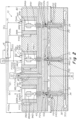
- Figure 1 is a schematic cross section of an injection molding system comprised of an electric or electronic actuator interconnected to a valve pin that has a flow control surface that interfaces with a surface of a flow channel at a selected position upstream of and away from the gate to control the rate of flow of injection fluid upstream of the gate during the course of an injection molding cycle, the electric or electronic actuators being interconnected to an electronic drive control device that is mounted to the housing of the electric or electronic actuator, the electronic drive control device receiving digital control and other signals from a remotely mounted controller containing a program that executes an algorithm for controlling operation of the electric or electronic actuator and the position of the valve pin within the flow channel during the course of an injection cycle.
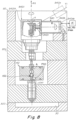
- Fig. 2 shows a sequential valve gated system showing three valves that have electric or electronic actuators that have a drive control mechanism that is integrated together with the body or housing of the actuator that houses the rotor and rotor drive components of the actuator.
- FIGS. 1 , 2 show exemplary embodiments of injection molding systems according to the present invention.
- the systems shown are multi-gate single cavity systems in which melt material 18 is injected into a cavity 5, 30 from gates 32, 34, 36.
- Melt material 18 is injected from the barrel 500 of an injection molding machine 13 through an extended inlet 5011 and into a heated distribution manifold 15, 40.
- Manifold 15, 40 distributes the melt through upstream channels 17, 19.
- a hot runner system is shown in which plastic melt is injected, the invention is applicable to other types of injection systems in which it is useful to control the rate at which a material (e.g., metallic or composite materials) is delivered to a cavity.
- a material e.g., metallic or composite materials
- Melt is distributed through channels 17, 19 and into bores 940c, 941c, 942c of nozzles 20, 21, 23 respectively. Melt is injected out of nozzles 20, 21, 23 and into cavities 5, 30 (where the part is formed) which is formed by mold plates 25, 27, 300.
- a multi-gate single-cavity system is shown, the invention is applicable to, for example, multi-cavity systems.
- the injection nozzles 20, 21, 23 are received in respective wells formed in the mold plates.
- the nozzles are typically each seated in support rings that serve to align the nozzles with the gates 32, 34, 36 and insulate the nozzles from the mold.
- An upstream end 1041ue of the valve pins 1040, 1041, 1042 is connected to an associated actuator 14, 940, 941, 942 that operate to drive the valve pins reciprocally upstream and downstream through the delivery channels 940c, 941c, 942c.
- the valve pin is opened at the beginning of the injection cycle starting from a fully closed position as shown for example in Figs. 3 , 3B and returned to a fully closed at the end of the cycle.
- the valve pin can assume intermediate positions between an upstream open position, in order to decrease or increase the rate of flow of the melt.
- a protrusion or head 102 is disposed between an upstream end 1041ue and downstream end 1041de.
- the protrusion includes a tapered portion 102m that forms an adjustably variable gap CGu, CGd with a surface 103s, 103s2 of the bore of the delivery channel of the manifold. Increasing or decreasing the size of the gap by displacing the valve pin correspondingly increases or decreases the flow of melt material to the gate.
- the valve pins 1040, 1041, 1042 can close and stop flow of injection fluid 18 in both a select upstream position as shown for example in Figs.
- valve pin 1040, 1041, 1042 When the valve pin 1040, 1041, 1042 is closed in a downstream position, in the embodiment shown in Figs. 3 , 3B the downstream end 1041de can be configured as a tapered portion as shown that contacts and seals with a complementary tapered gate surface GS.
- the gate surface can be configured in a cylindrical or other configuration to mate with a complementarily cylindrically configured distal end surface 1041de of a valve pin 940c, 941c, 942c.
- Melt flow rate is related to the material pressure sensed in a flow channel.
- the rate at which the melt flows through the gates 32, 34, 36 and into the cavities can be controllably adjusted during a given injection molding cycle, according to a predetermined desired pressure profile.
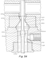
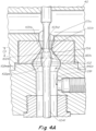
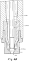
- Figs. 3 , 3A , 3B , 4 , 4A , 4B , 5 , 5A , 5B to reduce the rate or velocity of flow of melt 18, the pin 1041 can be retracted or controllably driven upstream away from the gate along a selected portion of a selected flow control path of travel CP as shown for example in Figs. 4A , 5A by an actuator 940, 941, 942 to thereby controllably decrease the width of a flow control gap CGd between the control surface 102m of the valve pin and the complementary control surface 103s of the bore of the downstream channel 940c, 941c, 942c.
- the rate or velocity of flow of melt 18 can be controllably variably increased by controllably driving the valve pin downstream along the selected portion of a selected flow control path of travel CP.
- the rate or velocity of flow of melt 18 can conversely be controllably increased by controllably driving the valve pin 1041, Figs. 3 , 3A , 3B , 4 , 4A , 4B , 5 , 5A , 5B , upstream away from the gate along another selected portion of a selected flow control path of travel beginning at and extending upstream of the throat 103t to controllably increase the width of a flow control gap CGu between the control surface 102m of the valve pin and another complementary control surface of the bore of the downstream channel 940c, 941c, 942c.
- the rate or velocity of flow of melt 18 can be controllably variably decreased by controllably driving the valve pin downstream along the same alternative selected portion of a selected flow control path of travel.
- the valve pin includes an extension (1041) extending downstream from the control surface (43, 45, 102m), the valve pin (1040, 1041, 1042) and the downstream feed channel (17, 19, 160, 940c, 941c, 942c) being configured such that in a first downstream position a distal end (1041de) of the valve pin closes the gate (32, 34, 36) and the interface between the control surface (43, 45, 102m) and the complementary surface (47, 103s) is not closed as shown in Figs 3-3B , and in a second upstream position, the distal end of the valve pin (1041de) does not close the gate (32, 34, 36) and the interface between the control surface (43, 45, 102m) and the complementary surface (47, 103s) is closed as shown in Fig. 5-5B .
- a material pressure transducer or sensor PS1, PS2, PS1a, PS2a can be used to sense the pressure of the injection material 18 either in the delivery channel 940c, 941c, 942c or within a fluid flow channel 17, 19 disposed within the manifold 40 or within a bushing 940b1, 940b2 having a fluid delivery channel that communicates with the downstream fluid delivery channel 940c, 941c, 942c.
- the material 18 pressure is sensed by a pressure sensor PS0, PS0a, PS1, PS2, PS1a, PS2a associated with each nozzle and is communicated in real time to a control system or controller 16.
- the controller 16 receives the pressure signals, compares them to a predetermined profile of pressures over the course of an injection cycle and sends drive signals DC to the electrical drives 940d, 941d, 942d that controllably distributes electrical energy or power in controllably varied amounts according to the drive signals (DC) to the drivers 940dr, 941dr, 942dr that drive the rotors of the electric actuators.
- the controller includes a processor and instructions that generate drive signals DC that result in the valve pin 1040, 1041, 1042 being driven upstream or downstream within a fluid delivery channel 940c, 941c, 942c to select positions during the course of an injection cycle so as to cause the pressure of the material 18 as measured in real time by the sensors PS0, PS1, PS2 to be adjusted to match or track the predetermined profile of preferred cycle material pressures such as in the examples described with reference to Figs. 11-13 .
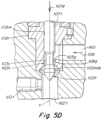
- Figs. 5C-5E show an alternative melt flow controller embodiment in which a pin 107t is slidably mounted in a mounting channel 108m having a protrusion or bulbous portion 102 without a downstream needle extension that can close the gate 34.
- the control surface (43, 45, 102m and complementary surface of the flow channel disposed upstream and away from the gate is the sole mechanism by which fluid flow is stopped at both the beginning and end of an injection cycle by positioning the pin 107t at a position as shown in Fig. 5C .
- the control surface 43, 45, 102m of Figs. 5-5C the control surface 43, 45, 102m of Figs.
- 5C-5E has a diameter equal to the maximum diameter of midsection 102md of the fluid contacting member 102 such that the pin 107t can be entirely withdrawn in the direction 107u from the manifold and bushing 108t and readily replaced without disassembling any portion of the manifold or bushing 108t.
- the maximum diameter midsection 102md typically has the same or about the same diameter as the complementary flow restricting throat surface 103s of the bushing 108t such that when the two surfaces mate flow is stopped.
- control surface 43, 45, 102m is illustrated as circular circumferential surface of a bulb or bulbous protrusion 102.
- the control surface 43, 45, 102m and its complementary channel surface 47, 103s can be configured to have any geometrical shape such as square, hexagonal, oval or the like other than circular as long as the two surfaces can mate or engage each other such that flow of injection material is stopped when the two surfaces mate or engage with each other.
- the rate of flow and the size of the flow rate determining gap 103g can be controllably varied by either upstream movement 107u, Fig. 5E or downstream movement, 107d, Fig. 5D of pin 107t.
- Upstream movement 107u can form gap 103g between bushing surface 108g, Fig. 5E , and the lower outer control surface 102t of member 102.
- Downstream movement 107d, Fig. 5D can also form a gap 103g between channel surfaces 103s, 108g and the upper portion of the outer control surface 102t of member 102.
- controlled movement of pin 107t by controller 16 controls the size of the gap 103g and thus the rate of flow from upstream channel 160 to downstream channel 162t which leads to downstream channel 190 or 200 or the like.
- Axis X of pin 107t as shown in Figs. 5D-5F is not coaxial with the axis of the downstream bore or flow channel such as channel 940c, 941c, 942c that leads at its distal end to a gate such as gate 32, 34, 36.
- Fig. 5F shows another embodiment of a valve having a pin that is non coaxially arranged relative to the axis of a downstream channel that delivers fluid to a gate of a cavity of a mold.
- the valve pin 107 has a protrusion 102 with an outside surface 102s which is complementary to a mating surface 103 disposed downstream of the protrusion within the flow channel 160.
- the fluid flow rate decreases on forward upstream movement 107u of pin 107.
- Upstream movement of a fluid contacting member, pin or the like means that the member moves against or in the opposite direction of the flow of the fluid.
- Downstream movement means that the member moves in the same direction as the flow of fluid.
- Upstream movement to decrease and/or stop flow rate is typically preferred.
- the rate of flow is increased by upstream movement of the fluid contacting member 102 and decreased by downstream movement.
- the position at which fluid flow rate is controlled is located within a channel 162a having an axis such as 104 which is not coaxial with the downstream channels 941c (not shown) that have an axis that intersects a gate leading to a mold cavity.
- the embodiments described control the rate of melt flow away from the gate along a channel axis offset from a channel having an axis intersecting and leading to a gate thus enabling control of flow rate to multiple channels intersecting multiple gates. Controlling the melt flow away from the gate also enables a pressure or other material condition sensor to be located away from a gate.
- the diameter 103td of the throat surface 103ts that is intended to mate with a complementary mating outer circumferential surface 102md, 102mds of the pin 1041 has a maximum diameter of about 10 to 12 mm and preferably a maximum diameter of about 8 to 9 mm such that upstream reactive forces exerted by the injection fluid on the pin and upstream to the motor rotor are minimized thus enabling use of a smaller sized electric motor actuator.
- the diameter 102pd of the mating surface 102mds of the pin 1041 is preferably adapted to be the same or about the same as the diameter 103td of the flow control throat surface 103ts such that when the pin 1041 is positioned in a position where the mating surface 102mds is axially aligned with the maximum diameter throat surface 103ts, injection material flow through the throat 103t, and thus through the gate 34, is stopped or substantially stopped.
- the controller 16 typically comprises for example a PID controller and a CPU.
- the CPU can execute a PID (proportional, integral, derivative) algorithm which compares the sensed pressure (at a given time) from the pressure sensor or transducer to a target pressure (for the given time).
- the CPU instructs the PID controller to adjust the position of the valve pin 1040, 1041, 1042 to mirror the target pressure for that given time by instructing the electric actuator via communication of control drive signals DC through the electrical drive 940d, 941d, 942d.
- the sensed condition is preferably pressure
- other sensed conditions can be used which relate to melt flow rate.
- the position of the valve pin. Pressure is typically measured by a pressure transducer that measures pressure of the injection material directly or indirectly such as via measurement of the load on the valve pin via a load sensor.
- a position sensor could be used to feed back the sensed condition (position) to the PID controller.
- the CPU would use a PID algorithm to compare the sensed condition to a programmed target position profile or load profile for the particular gate to the mold cavity, and adjust the valve pin accordingly.
- a sensor that senses position of the valve pin directly can be used such as a Hall Effect sensor or a light sensor.
- a sensor that detects position of the rotor of the electric actuator such as an encoder, could be used to generate a position signal that is indicative of the position of the valve pin.
- controller As used in this application with regard to various monitoring and control systems, the terms “controller,” “component,” “computer” and the like are intended to refer to a computer-related entity, either hardware, a combination of hardware and software, software, or software in execution.
- a component or controller may be, but is not limited to being, a process running on a processor, a processor, an object, an executable, a thread of execution, a program, and/or a computer.
- an application running on a server and the server can be a component.
- One or more components may reside within a process and/or thread of execution and a component may be localized on one computer and/or distributed between two or more computers.
- Claimed methods of the present invention may also be illustrated as a flow chart of a process of the invention. While, for the purposes of simplicity of explanation, the one or more methodologies shown in the form of a flow chart are described as a series of acts, it is to be understood and appreciated that the present invention is not limited by the order of acts, as some acts may, in accordance with the present invention, occur in a different order and/or concurrent with other acts from that shown and described herein. For example, those skilled in the art will understand and appreciate that a methodology could alternatively be represented as a series of interrelated states or events, such as in a state diagram. Moreover, not all illustrated acts may be required to implement a methodology in accordance with the present invention.
- data means any sequence of symbols (typically denoted “0” and “1") that can be input into a computer, stored and processed there, or transmitted to another computer.
- data includes metadata, a description of other data.
- Data written to storage may be data elements of the same size, or data elements of variable sizes. Some examples of data include information, program code, program state, program data, other data, and the like.
- Computer storage media or the like includes both volatile and non-volatile, removable and non-removable media for storage of information such as computer-readable instructions, data structures, program modules, or other data.
- Computer storage media includes RAM, ROM, EEPROM, FLASH memory or other memory technology, CD-ROM, digital versatile disc (DVDs) or other optical disk storage, magnetic cassettes, magnetic tape, magnetic disk storage or other magnetic storage devices, or any other medium which can be used to store desired information and which can be accessed by the computer.
- the methods described herein may be implemented in a suitable computing and storage environment, e.g., in the context of computer-executable instructions that may run on one or more processors, microcontrollers or other computers.
- a distributed computing environment for example
- certain tasks are performed by remote processing devices that are linked through a communications network and program modules may be located in both local and remote memory storage devices.
- the communications network may include a global area network, e.g., the Internet, a local area network, a wide area network or other computer network. It will be appreciated that the network connections described herein are exemplary and other means of establishing communications between the computers may be used.
- a computer may include one or more processors and memory, e.g., a processing unit, a system memory, and system bus, wherein the system bus couples the system components including, but not limited to, the system memory and the processing unit.
- a computer may further include disk drives and interfaces to external components.
- a variety of computer-readable media can be accessed by the computer and includes both volatile and nonvolatile media, removable and nonremovable media.
- a computer may include various user interface devices including a display screen, touch screen, keyboard or mouse.
- a “controller,” as used herein also refers to electrical and electronic control apparatus that comprise a single box or multiple boxes (typically interconnected and communicating with each other) that contain(s) all of the separate electronic processing, memory and electrical signal generating components that are necessary or desirable for carrying out and constructing the methods, functions and apparatuses described herein.
- Such electronic and electrical components include programs, microprocessors, computers, PID controllers, voltage regulators, current regulators, circuit boards, motors, batteries and instructions for controlling any variable element discussed herein such as length of time, degree of electrical signal output and the like.
- a component of a controller includes programs, controllers and the like that perform functions such as monitoring, alerting and initiating an injection molding cycle including a control device that is used as a standalone device for performing conventional functions such as signaling and instructing an individual injection valve or a series of interdependent valves to start an injection, namely move an actuator and associated valve pin from a gate closed to a gate open position.
- a control device that is used as a standalone device for performing conventional functions such as signaling and instructing an individual injection valve or a series of interdependent valves to start an injection, namely move an actuator and associated valve pin from a gate closed to a gate open position.
- actuators powered by an electric or electronic motor or drive source can alternatively be used as the actuator component.
- the injection molding machine IMM, 500, 13 typically includes its own internal manufacturer supplied machine controller that generates standardized beginning of cycle gate closed and end of cycle gate open and gate closed machine voltage signals VS typically 0 volts for gate open and 24 volts for gate open (or 0 volts and 120 volts respectively).
- the standardized machine voltage signals VS can be sent to a signal conversion device that converts the injection machine voltage signals to a signal usable by the controller 16 and the electric drive (940d, 941d, 942d) of an electric actuator to cause the electric actuator to move the valve pin to a gate closed or gate open actuator position.
- the controller (16) can utilize these start and end of injection cycle signals together with position signals (POS0s, POS1s, POS2s) that are indicative of position of the valve pin 1040, 1041, 1042 that are generated by a position sensor (POS0, POS1, POS2), to instruct an electric actuator (940, 941, 942) to drive or move a valve pin to one or more predetermined positions such as a start or end cycle position.
- position signals POS0s, POS1s, POS2s
- the position signals can be used by the controller to instruct the actuator to move or drive the valve pin to another intermediate position during the course of an injection cycle such as a position at which the pin serves to control rate of injection fluid flow or injection material pressure such that the injection material is held at a "pack" phase pressure for a predetermined period of time prior to the end of the cycle when the gate to the cavity is closed.
- the position sensor signals POS0s, POS1s, POS2s and their associated position sensors POS, PS0, PS1, PS2, PSOa, PS1a, PS2a can also be used as an input to a set of instructions included in the program contained in controller 16 that operates to correct or adjust axial position of the valve pin 1040, 1041, 1042 by a predetermined degree either upstream or downstream depending on the difference between the value of the target or predetermined pressure profile and the value of the real time pressure sensed at any given point in time during the injection cycle.
- the degree of adjustment or correction in axial positioning of the valve pin, and thus the precise positioning of the axial positioning of control surface 102m, 102t is the degree or amount of travel distance that is required to reduce or increase the real time pressure to match or to approach the value of the predetermined target pressure at any given point in time during the course of the injection cycle.
- This degree of adjustment distance is predetermined and is input to the program as a variable that is utilized in the control program to send movement adjustment signals from the controller 16 to the electric drive 940d, 941d, 942d for an actuator.
- the goal of the program is to instruct the actuators to drive the valve pins to an axial position over the course of the entire injection cycle that produces a sensed or real time injection material pressure that matches the predetermined profile of target pressures as closely as possible.
- the program contained within the controller (16) preferably includes instructions that utilize a position signal POS0s, POS1s, POS2s to instruct an actuator (14, 940, 941, 942) to move a corresponding valve pin (1040, 1041, 1042) to one or more predetermined positions during the course of an injection cycle that can include one or more of (a) an initial position of the valve pin (1040, 1041, 1042) at start of the injection cycle, (b) an end position of the valve pin at the end of the injection cycle, and (c) one or more intermediate positions of the valve pin between the initial position and the end position.
- a position signal POS0s, POS1s, POS2s to instruct an actuator (14, 940, 941, 942) to move a corresponding valve pin (1040, 1041, 1042) to one or more predetermined positions during the course of an injection cycle that can include one or more of (a) an initial position of the valve pin (1040, 1041, 1042) at start of the injection cycle, (b
- the program can include instructions that utilize the position signal (POS0s, POS1s, POS2s) to adjust sensed axial position of the valve pin by a travel distance or amount that causes the control surface (102m, 102t) to adjust real time pressure of the injection material at one or more times over the course of the injection cycle to a value that approaches or matches a predetermined target pressure value for the one or more times over the course of the injection cycle.
- POS0s, POS1s, POS2s to adjust sensed axial position of the valve pin by a travel distance or amount that causes the control surface (102m, 102t) to adjust real time pressure of the injection material at one or more times over the course of the injection cycle to a value that approaches or matches a predetermined target pressure value for the one or more times over the course of the injection cycle.
- the program can include instructions that utilize a predetermined error value to determine the travel distance.
- the predetermined error value typically corresponds or is proportional to one or more of (a) an error in accuracy of the value of sensed pressure and (b) a difference in value between sensed pressure and the predetermined target pressure.
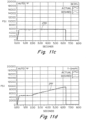
- Figs. 11a, 11b , 11c, 11d show time versus pressure graphs (235, 237, 239, 241) of the pressure detected by four pressure transducers associated with four nozzles mounted in a manifold block (not shown).
- the four nozzles can be substantially similar to or the same as the nozzles shown in FIGS. 1-5C and include pressure transducers interconnected to a controller 16 as described herein.
- the Figs. 11a-d plots are generated on a user interface 214 so that a user can observe the tracking of the actual pressure versus the target pressure during the injection cycle in real time, or after the cycle is complete.
- 11a-11d show as an example four independent target pressure profiles ("desired") emulated by the four individual nozzles. Different target profiles are desirable to uniformly fill different sized individual cavities associated with each nozzle, or to uniformly fill different sized sections of a single cavity. Graphs such as these can be generated with respect to any of the previous embodiments described herein.
- valve pin associated with plot 235 is opened sequentially at 0.5 seconds after the valves associated with the other three graphs (237, 239 and 241) were opened at 0.00 seconds.
- the valve pins are in the position shown in Figs. 5 , 5A , 5B such that flow is stopped at the throat 103t.
- all four valve pins are in the position shown in Figs.
- each valve pin is controlled to a plurality of positions such as Figs. 4 , 4A , 4B between the Figs. 3 and 5 to alter the pressure sensed by the pressure transducer PS0, PS1, PS1a, PS2, PS2a associated with each valve to track the target pressure.
- target profiles can be designed, and changes can be made to any of the target profiles using standard windows based editing techniques.
- the profiles are then input to memory and used by controller 16 to control the position of the valve pin.
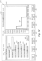
- FIG. 12 shows an example of a profile creation and editing screen icon 300 generated on interface 214.
- Screen icon 300 is generated by a windows-based application performed on interface 214. Alternatively, this icon could be generated on an interface associated with controller 6. Screen icon 300 provides a user with the ability to create a new target profile or edit an existing target profile for any given nozzle and cavity associated therewith.
- a profile 310 includes (x, y) data pairs, corresponding to time values 320 and pressure values 330 which represent the desired pressure sensed by the pressure transducer for the particular nozzle being profiled.
- the screen icon shown in FIG. 12 is shown in a "basic" mode in which a limited group of parameters are entered to generate a profile.
- the "basic" mode permits a user to input start time displayed at 340, maximum fill pressure displayed at 350 (also known as injection pressure), the start of pack time displayed at 360, the pack pressure displayed at 370, and the total cycle time displayed at 380.
- the screen also allows the user to select the particular valve pin they are controlling displayed at 390, and name the part being molded displayed at 400.
- Each of these parameters can be adjusted independently using standard windows-based editing techniques such as using a cursor to actuate up/down arrows 410, or by simply typing in values on a keyboard. As these parameters are entered and modified, the profile will be displayed on a graph 420 according to the parameters selected at that time.
- a pull-down menu arrow 391 the user can select different nozzle valves in order to create, view or edit a profile for the selected nozzle valve and cavity associated therewith. Also, a part name 400 can be entered and displayed for each selected nozzle valve.
- the newly edited profile can be saved in computer memory individually, or saved as a group of profiles for a group of nozzles that inject into a particular single or multi-cavity mold.
- the term "recipe" is used to describe a group of profiles for a particular mold and the name of the particular recipe is displayed at 430 on the screen icon.
- a particular nozzle valve of the group of valves for the particular recipe group being profiled is displayed at 390.
- the user inputs an alpha/numeric name to be associated with the profile being created, for family tool molds this may be called a part name displayed at 400.
- the user then inputs a time displayed at 340 to specify when injection starts.
- a delay can be with particular valve pins to sequence the opening of the valve pins and the injection of melt material into different gates of a mold.
- the user then inputs the fill (injection) pressure displayed at 350.
- the ramp from zero pressure to max fill pressure is a fixed time, for example, 0.3 seconds.
- the user next inputs the start pack time to indicate when the pack phase of the injection cycle starts.
- the ramp from the filling phase to the packing phase is also fixed time in the basic mode, for example, 0.3 seconds.
- the final parameter is the cycle time which is displayed at 380 in which the user specifies when the pack phase (and the injection cycle) ends.
- the ramp from the pack phase to zero pressure will be instantaneous when a valve pin is used to close the gate, as in the embodiment of FIG. 13 , or slower in a thermal gate (see FIG. 1 ) due to the residual pressure in the cavity which will decay to zero pressure once the part solidifies in the mold cavity.
- buttons 415 through 455 are used to save and load target profiles.
- Button 415 permits the user to close the screen. When this button is clicked, the current group of profiles will take effect for the recipe being profiled. Cancel button 425 is used to ignore current profile changes and revert back to the original profiles and close the screen.
- Read Trace button 435 is used to load an existing and saved target profile from memory. The profiles can be stored in memory contained in the interface 215 or the controller 210.
- Save trace button 440 is used to save the current profile.
- Read group button 445 is used to load an existing recipe group.
- Save group button 450 is used to save the current group of target profiles for a group of nozzle valve pins.
- the process tuning button 455 allows the user to change the PID settings (for example, the gains) for a particular nozzle valve in a control zone. Also displayed is a pressure range 465 for the injection molding application.
- Button 460 permits the user to toggle to an "advanced" mode profile creation and editing screen.
- the advanced profile creation and editing screen is shown in FIG. 13 .
- the advanced mode allows a greater number of profile points to be inserted, edited, or deleted than the basic mode.
- the profile is changed, the resulting profile is displayed.
- the advanced mode offers greater profilability because the user can select values for individual time and pressure data pairs.
- the profile 470 displayed is not limited to a single pressure for fill and pack, respectively, as in the basic mode. In the advanced mode, individual (x, y) data pairs (time and pressure) can be selected anywhere during the injection cycle.
- the user can select a plurality of times during the injection cycle (for example 16 different times), and select a pressure value for each selected time.
- a plurality of times during the injection cycle for example 16 different times
- select a pressure value for each selected time Using standard windows-based editing techniques (arrows 475) the user assigns consecutive points along the profile (displayed at 478), particular time values displayed at 480 and particular pressure values displayed at 485.
- the button 490 is used to select the next point on the profile for editing.
- Prev button 495 is used to select the previous point on the profile for editing.
- Delete button 500 is used for deleting the currently selected point. When the delete button is used the two adjacent points will be redrawn showing one straight line segment.
- the add button 510 is used to add a new point after the currently selected point in which time and pressure values are entered for the new point.
- the add button is used the two adjacent points will be redrawn showing two segments connecting to the new point.
Landscapes
- Engineering & Computer Science (AREA)
- Manufacturing & Machinery (AREA)
- Mechanical Engineering (AREA)
- Injection Moulding Of Plastics Or The Like (AREA)
- Moulds For Moulding Plastics Or The Like (AREA)
Claims (16)
- Spritzgießvorrichtung (1), mit: einer Spritzgießmaschine (500), einem Verteiler (15), der ein Einspritzmaterial (18) unter Druck von der Spritzgießmaschine (500) empfängt, einer Form (25, 27, 300) mit einem Hohlraum (5, 30) und mindestens einem Ventil, aufweisend:einen Aktuator (14, 940, 941, 942) mit einem Rotor (940r, 941r, 942r), der durch elektrische Energie steuerbar drehbar ist, wobei der Aktuator (14, 940, 941, 942) mit einer Steuereinheit (16) verbunden ist, die Ansteuersignale (DC) erzeugt;eine elektrische Antriebsvorrichtung (940d, 941d, 942d) mit einer Schnittstelle, die die Ansteuersignale (DC) empfängt und steuerbar elektrische Energie oder Leistung in steuerbar veränderten Mengen gemäß den Ansteuersignalen (DC) an eine Antriebseinrichtung (940dr, 941dr, 942dr) verteilt, die den Rotor (940r, 941r, 942r) antreibt;einen Ventilstift (1040, 1041, 1042), der eine Welle mit einer Achse (X) und eine Steuerfläche (43, 45, 102m) aufweist, die an einer ausgewählten Position entlang der Achse (X) der Welle angeordnet ist, wobei der Ventilstift an einem stromaufwärtsseitigen Ende mit dem Rotor in einer Anordnung verbunden ist, wobei der Ventilstift entlang eines linearen Bewegungspfades (XX) stromaufwärts und stromabwärts durch einen stromabwärtsseitigen Zufuhrkanal (17, 19, 160, 940c, 941c, 942c) steuerbar antreibbar ist, der das Einspritzmaterial zu und durch einen Angusskanal (7, 9, 32, 34, 36) leitet, der zum Hohlraum der Form führt,wobei der stromabwärtsseitige Zufuhrkanal eine komplementäre Oberfläche (47, 103s) aufweist, die dazu geeignet ist, mit der Steuerfläche (43, 45, 102m) zusammenzuwirken, um eine Durchflussmenge oder eine Fließgeschwindigkeit gemäß der gesteuerten axialen Positionierung der Steuerfläche (43, 45, 102m) relativ zur komplementären Oberfläche (47, 103s) des stromabwärtsseitigen Zufuhrkanals (17, 19, 160, 940c, 941c, 942c) steuerbar zu verändern.
- Vorrichtung nach Anspruch 1, wobei die komplementäre Oberfläche (47, 103s) stromaufwärts und entfernt vom Angusskanal (7, 9, 32, 34, 36) angeordnet ist.
- Vorrichtung nach einem der vorangehenden Ansprüche, wobei die elektrische Antriebsvorrichtung (940d, 941d, 942d) elektrische Energie oder Leistung von einer Leistungsquelle (PS) empfängt und die empfangene elektrische Energie oder Leistung im Verlauf eines Einspritzzyklus in steuerbar veränderten Mengen an die Antriebseinrichtung (940dr, 941dr, 942dr) steuerbar verteilt.
- Vorrichtung nach einem der vorangehenden Ansprüche, wobei die elektrische Antriebsvorrichtung (940d, 941d, 942d) einen Pulsbreitenmodulator (PWM) enthält, der die empfangene elektrische Energie oder Leistung in sinusförmige Spannungswellenformen umwandelt, wobei jede sinusförmige Spannungswellenform dazu geeignet ist, eine entsprechende Phasenspule der Aktuatorantriebseinrichtung (940dr, 941 dr, 942dr) anzusteuern.
- Vorrichtung nach Anspruch 4,wobei der Pulsbreitenmodulator (PWM) einen Wechselrichter oder einen Komparator aufweist, und/oderwobei der Pulsbreitenmodulator (PWM) einen dreiphasigen Wechselrichter aufweist, der elektrische Energie oder Leistung, die von der Schnittstelle empfangen wird, in drei sinusförmige Spannungswellenformen umwandelt, wobei jede der drei sinusförmigen Spannungswellenformen dazu geeignet ist, eine entsprechende von drei Phasenspulen der Aktuatorantriebseinrichtung anzusteuern, und/oderwobei die elektrische Energie oder Leistung, die am oder durch den Pulsbreitenmodulator (PWM) empfangen wird, eine Gleichstrom-Busspannung aufweist.
- Vorrichtung nach einem der vorangehenden Ansprüche,wobei die Schnittstelle der elektrischen Antriebsvorrichtung (940d, 941d, 942d) dazu geeignet ist, ein oder mehrere Steuersignale von einer Steuereinheit (16) der Spritzgießvorrichtung (1) zu empfangen und die von der Leistungsquelle (PS) empfangene elektrische Energie oder Leistung basierend auf dem einen oder den mehreren Steuersignalen in sinusförmige Wellenformen umzuwandeln, und/oderwobei die Schnittstelle den Pulsbreitenmodulator (PWM) aufweist, der die von der Leistungsquelle empfangene elektrische Energie oder Leistung basierend auf dem einen oder den mehreren Steuersignalen in sinusförmige Wellenformen umwandelt.
- Vorrichtung nach einem der vorangehenden Ansprüche,wobei das eine oder die mehreren durch die Schnittstelle empfangenen Steuersignale Steuerinformation enthalten, die den Pulsbreitenmodulator (PWM) veranlassen, die empfangene elektrische Energie oder Leistung in sinusförmige Wellenformen umzuwandeln, die dazu geeignet sind, die entsprechenden Phasenspulen der Aktuatorantriebseinrichtung anzusteuern, um einen oder mehr Parameter unter einer Position, einer Geschwindigkeit oder einem Drehmoment des Aktuatorrotors (940r, 941r, 942r) einzustellen, und/oderwobei das eine oder die mehreren Steuersignale analoge elektrische Signale aufweisen, die an der elektrischen Antriebsvorrichtung von der Steuereinheit (16) empfangen werden.
- Vorrichtung nach einem der vorangehenden Ansprüche, wobei die elektrische Antriebsvorrichtung (940d, 941d, 942d) eine Digitalsignalempfangs-(16r) und/oder -sendeeinrichtung (16s) aufweist, wobei: die Digitalsignalempfangs- und -sendeeinrichtung dazu eingerichtet ist, Digitalsignale zwischen der elektrischen Antriebsvorrichtung (940d, 941d, 942d) und der Steuereinheit (16) der Spritzgießvorrichtung (1) zu empfangen (16r) und zu übertragen (16s), und wobei die Digitalsignale das eine oder die mehreren Steuersignale aufweisen, wobei das eine oder die mehreren Steuersignale digitale Steuersignale sind, die von der Steuereinheit empfangen werden,
wobei vorzugsweise die digitalen Steuersignale einen oder mehrere Differenzpositionsbefehle, Differenzstrombefehle und Differenzgeschwindigkeitsbefehle aufweisen. - Vorrichtung nach Anspruch 8, wobei die Digitalsignalempfangs- und -sendeeinrichtung (16r, 16s) dazu eingerichtet ist, Digitalsignale vom Aktuator zu empfangen, wobei die vom Aktuator empfangenen Digitalsignale ein oder mehrere Rückkopplungssignale aufweisen, die einem Betrieb des Aktuators und/oder des Aktuatorrotors entsprechen, wobeidie Digitalsignalempfangs- und -sendeeinrichtung (16r, 16s) dazu eingerichtet ist, an die Steuereinheit (16) ein Positionssignal (16s) zu übertragen, das eine Position des Ventilstifts anzeigt, und/oderder Pulsbreitenmodulator (PWM) die von der Schnittstelle empfangene elektrische Energie oder Leistung in sinusförmige Wellenformen umwandelt, die dazu geeignet sind, die entsprechenden Phasenspulen der Aktuatorantriebseinrichtung zumindest teilweise basierend auf dem einen oder den mehreren Rückkopplungssignalen anzusteuern, und/oderdas eine oder die mehreren vom Aktuator empfangenen Rückkopplungssignale ein inkrementelles Rückkopplungssignal und/oder ein absolutes Rückkopplungssignal aufweisen.
- Vorrichtung nach einem der vorangehenden Ansprüche, wobei der Aktuator ein Gehäuse (940h, 941h, 942h) aufweist, das den Rotor (940r, 941r, 942r) und die Antriebseinrichtung (940dr, 941dr, 942dr) aufnimmt, wobei das Gehäuse dazu eingerichtet ist, den Rotor (940r, 941r, 942r) zu tragen,
wobei die elektrische Antriebsvorrichtung (940d, 941d, 942d) im oder durch das Gehäuse (940h, 941h, 942h) aufgenommen oder daranmontiert ist, wobei das Gehäuse (940h, 941h, 942h) in der Nähe des geheizten Verteiler (40) montiert oder relativ dazu angeordnet ist, derart, dass das Gehäuse (940h, 941h, 942h) und/oder die elektrische Antriebsvorrichtung (940d, 941d, 942d) in wesentlicher Wärmekommunikation oder in wesentlichem Wärmekontakt mit dem geheizten Verteiler (40) steht oder stehen. - Vorrichtung nach Anspruch 10, wobei das Gehäuse (940h, 941h, 942h) auf oder an einer Klemmplatte (80) in einer derartigen Anordnung montiert ist, dass das Gehäuse (940h, 941h, 942h) und/oder die elektrische Antriebsvorrichtung (940d, 941d, 942d) in wesentlicher Wärme- oder thermischer Kommunikation mit dem geheizten Verteiler (40) steht oder stehen.
- Vorrichtung nach Anspruch 10 oder 11, wobei das Gehäuse (940h, 941h, 942h) des Aktuators mit einem Linearbewegungswandler (940l, 941l, 942l) in einer Anordnung verbunden ist, bei der der Ventilstift (1040, 1041, 1042) dazu eingerichtet ist, entlang einer linearen Achse (X) angetrieben zu werden, die sich nicht koaxial zur Antriebsachse (y) erstreckt, wobei der Linearbewegungswandler (940I, 941l, 942I) auf oder an dem geheizten Verteiler (40) montiert oder in wärmeleitender Kommunikation damit angeordnet ist.
- Vorrichtung nach Anspruch 12,wobei der Linearbewegungswandler (940I, 941l, 942I) auf oder am geheizten Verteiler (40) und/oder einer Klemmplatte (80) montiert ist; und/oderwobei der Linearbewegungswandler ein Wandlergehäuse (940lh) aufweist, das in direktem oder indirektem wärmeleitendem Kontakt mit dem geheizten Verteiler (40) montiert ist, wobei das Gehäuse (940h, 941h, 942h) mit dem Wandlergehäuse (940lh) in wärmeleitendem Kontakt verbunden ist, und/oderwobei der Linearbewegungswandler ein Wandlergehäuse (940lh) aufweist, das auf oder an Halterungen montiert ist, die aus einem Metallmaterial bestehen und in direktem Metall-Metall-Kontakt oder in direkter Metall-Metall-Verbindung mit dem geheizten Verteiler (40) montiert sind.
- Vorrichtung nach einem der vorangehenden Ansprüche, wobei der Ventilstift (1040, 1041, 1042) ein stromaufwärtsseitiges Ende (1041ue), das mit dem Aktuator verbunden ist, und ein stromabwärtsseitiges Ende (1041de) aufweist, das den Angusskanal bei einer stromabwärtsseitigen Bewegung des Ventilstifts in eine geschlossene Angusskanalposition schließt, wobei die Steuerfläche (43, 45, 102m) in einer ausgewählten axialen Position zwischen dem stromaufwärtsseitigen Ende (1041ue) und dem stromabwärtsseitigen Ende (1041de) angeordnet und dazu eingerichtet ist, mit der komplementären Fläche (103s) zusammenzuwirken, um die Materialflussrate bei einer stromaufwärtsseitigen Bewegung des Ventilstifts durch einen ausgewählten Bewegungspfad (CP) zu vermindern und die Materialflussrate bei einer stromabwärtsseitigen Bewegung des Ventilstifts durch den ausgewählten Bewegungspfad (CP) zu erhöhen.
- Vorrichtung nach einem der vorangehenden Ansprüche, ferner mit einem Sensor (PSO, PS1, PS1a, PS2, PS2a), der den Druck des Einspritzmaterials erfasst, wobei der Sensor (PSO, PS1, PS1a, PS2, PS2a) ein den erfassten Druck anzeigendes Signal an die Steuereinheit (16) überträgt, wobei die Steuereinheit Anweisungen enthält, die den erfassten Druck mit einem Solldruck vergleichen und die axiale Position des Ventilstifts derart einstellen, dass der Materialdruck so eingestellt wird, dass er dem Solldruck folgt,
wobei der Sensor vorzugsweise dazu eingerichtet ist, den Druck des Einspritzmaterials an einer Position stromabwärts von der Steuerfläche des Ventilstifts zu erfassen. - Verfahren zum Ausführen eines Spritzgießzyklus, mit dem Betreiben einer Vorrichtung nach einem der vorangehenden Ansprüche.
Applications Claiming Priority (3)
| Application Number | Priority Date | Filing Date | Title |
|---|---|---|---|
| US201962923656P | 2019-10-21 | 2019-10-21 | |
| US202062978928P | 2020-02-20 | 2020-02-20 | |
| PCT/US2020/054354 WO2021080767A1 (en) | 2019-10-21 | 2020-10-06 | Electric actuator drive for injection molding flow control |
Publications (2)
| Publication Number | Publication Date |
|---|---|
| EP4041523A1 EP4041523A1 (de) | 2022-08-17 |
| EP4041523B1 true EP4041523B1 (de) | 2024-11-20 |
Family
ID=75490982
Family Applications (1)
| Application Number | Title | Priority Date | Filing Date |
|---|---|---|---|
| EP20797611.9A Active EP4041523B1 (de) | 2019-10-21 | 2020-10-06 | Elektrischer stellantrieb für spritzgiessflusssteuerung |
Country Status (3)
| Country | Link |
|---|---|
| US (1) | US11389999B2 (de) |
| EP (1) | EP4041523B1 (de) |
| CN (1) | CN115210058B (de) |
Families Citing this family (1)
| Publication number | Priority date | Publication date | Assignee | Title |
|---|---|---|---|---|
| JP2023140736A (ja) * | 2022-03-23 | 2023-10-05 | キヤノン株式会社 | 製造装置、製造システム、及び物品の製造方法 |
Family Cites Families (20)
| Publication number | Priority date | Publication date | Assignee | Title |
|---|---|---|---|---|
| US5362222A (en) * | 1993-08-31 | 1994-11-08 | Cincinnati Milacron Inc. | Injection molding machine having a vector controlled AC drive system |
| US6294122B1 (en) * | 1998-06-26 | 2001-09-25 | Synventive Molding Solutions, Inc. | Electric actuator for a melt flow control pin |
| US6309208B1 (en) * | 1997-06-13 | 2001-10-30 | Synventive Molding Solutions, Inc. | Apparatus for proportionally controlling fluid delivery to a mold |
| US6464909B1 (en) | 1998-04-21 | 2002-10-15 | Synventive Molding Solutions, Inc. | Manifold system having flow control |
| US7029268B2 (en) * | 2001-12-26 | 2006-04-18 | Synventive Molding Solutions, Inc. | Non-coaxial injection molding valve flow control |
| CA2457643C (en) * | 2003-02-13 | 2011-11-22 | Mold-Masters Limited | Valve gated injection molding system with independent flow control |
| US20040166189A1 (en) * | 2003-02-25 | 2004-08-26 | Mold-Masters Limited | Injection molding system with flow control |
| US8091202B2 (en) | 2009-05-06 | 2012-01-10 | Synventive Molding Solutions, Inc. | Method and apparatus for coupling and uncoupling an injection valve pin |
| US20180015652A1 (en) * | 2010-11-23 | 2018-01-18 | Synventive Molding Solutions, Inc. | Injection flow control apparatus and method |
| US9724861B2 (en) * | 2011-11-23 | 2017-08-08 | Synventive Molding Solutions, Inc. | Fast acting reduced velocity pin control |
| US10899056B2 (en) * | 2011-11-23 | 2021-01-26 | Synventive Molding Solutions, Inc. | Non-coaxially mounted electric actuator and transmission |
| US9440389B2 (en) * | 2011-11-23 | 2016-09-13 | Synventive Molding Solutions, Inc. | Controlled valve pin movement based on cavity sensor feedback |
| EP2888091B1 (de) * | 2012-08-24 | 2018-07-04 | Synventive Molding Solutions, Inc. | Spritzguss-flusssteuerungsvorrichtung und -verfahren |
| CN105121120B (zh) * | 2012-11-27 | 2017-09-26 | 圣万提注塑工业(苏州)有限公司 | 注射成型流量控制装置及方法 |
| US9662820B2 (en) * | 2013-12-13 | 2017-05-30 | Synventive Molding Solutions, Inc. | Pneumatically driven, pin velocity controlled injection molding apparatus and method |
| CN105283296B (zh) * | 2013-04-19 | 2017-10-17 | 圣万提注塑工业(苏州)有限公司 | 基于腔传感器反馈的受控阀销运动 |
| EP3062985B1 (de) * | 2013-10-28 | 2019-03-20 | Synventive Molding Solutions, Inc. | Steuerung mit reduzierter geschwindigkeit je nach erfasstem systemzustand |
| ITUB20156839A1 (it) * | 2015-12-10 | 2017-06-10 | Inglass Spa | Apparecchiatura di stampaggio ad iniezione di materie plastiche |
| WO2017210169A1 (en) * | 2016-06-01 | 2017-12-07 | Synventive Molding Solutions, Inc. | Controller arrangement for injection molding system |
| CN110461566B (zh) * | 2017-04-18 | 2022-01-11 | 圣万提注塑工业(苏州)有限公司 | 注射循环期间的线性到线性阀销驱动 |
-
2020
- 2020-10-06 EP EP20797611.9A patent/EP4041523B1/de active Active
- 2020-10-06 CN CN202080089060.9A patent/CN115210058B/zh active Active
- 2020-12-30 US US17/137,477 patent/US11389999B2/en active Active
Also Published As
| Publication number | Publication date |
|---|---|
| US11389999B2 (en) | 2022-07-19 |
| US20210114271A1 (en) | 2021-04-22 |
| EP4041523A1 (de) | 2022-08-17 |
| CN115210058B (zh) | 2025-06-10 |
| CN115210058A (zh) | 2022-10-18 |
Similar Documents
| Publication | Publication Date | Title |
|---|---|---|
| US7597828B2 (en) | Injection molding valve flow control | |
| US10926445B2 (en) | Controller arrangement for injection molding system | |
| US20170305052A1 (en) | Pneumatically driven, pin velocity controlled injection molding apparatus and method | |
| US7419625B2 (en) | Injection molding flow control method | |
| EP3062985B1 (de) | Steuerung mit reduzierter geschwindigkeit je nach erfasstem systemzustand | |
| CN110366484B (zh) | 阀销位置和速度控制方法及装置 | |
| US9005509B2 (en) | Injection molding flow control apparatus and method | |
| EP2961586B1 (de) | Schnell agierende nadelsteuerung mit reduzierter geschwindigkeit | |
| JP2003522654A (ja) | 動的給送制御システム | |
| EP2931491B1 (de) | Pneumatisch angetriebene stiftgeschwindigkeitsgesteuerte spritzgussvorrichtung und verfahren | |
| EP2976203B1 (de) | Pneumatisch gesteuertes ventil mit reduzierter geschwindigkeit | |
| US20180015652A1 (en) | Injection flow control apparatus and method | |
| EP4041523B1 (de) | Elektrischer stellantrieb für spritzgiessflusssteuerung | |
| WO2021080767A1 (en) | Electric actuator drive for injection molding flow control | |
| US11524435B2 (en) | Injection molding apparatus with integrated actuator electronic drive | |
| US12172354B2 (en) | Electric actuator drive for injection molding flow control | |
| US20230373142A1 (en) | Electro Fluid Driven Actuator and Method | |
| WO2019066776A1 (en) | APPARATUS AND METHOD FOR CONTROLLING INJECTION MOLDING FLOW |
Legal Events
| Date | Code | Title | Description |
|---|---|---|---|
| STAA | Information on the status of an ep patent application or granted ep patent |
Free format text: STATUS: UNKNOWN |
|
| STAA | Information on the status of an ep patent application or granted ep patent |
Free format text: STATUS: THE INTERNATIONAL PUBLICATION HAS BEEN MADE |
|
| PUAI | Public reference made under article 153(3) epc to a published international application that has entered the european phase |
Free format text: ORIGINAL CODE: 0009012 |
|
| STAA | Information on the status of an ep patent application or granted ep patent |
Free format text: STATUS: REQUEST FOR EXAMINATION WAS MADE |
|
| 17P | Request for examination filed |
Effective date: 20220512 |
|
| AK | Designated contracting states |
Kind code of ref document: A1 Designated state(s): AL AT BE BG CH CY CZ DE DK EE ES FI FR GB GR HR HU IE IS IT LI LT LU LV MC MK MT NL NO PL PT RO RS SE SI SK SM TR |
|
| DAV | Request for validation of the european patent (deleted) | ||
| DAX | Request for extension of the european patent (deleted) | ||
| GRAP | Despatch of communication of intention to grant a patent |
Free format text: ORIGINAL CODE: EPIDOSNIGR1 |
|
| STAA | Information on the status of an ep patent application or granted ep patent |
Free format text: STATUS: GRANT OF PATENT IS INTENDED |
|
| RIC1 | Information provided on ipc code assigned before grant |
Ipc: B29C 45/27 20060101ALI20240430BHEP Ipc: B29C 45/74 20060101ALI20240430BHEP Ipc: B29C 45/30 20060101ALI20240430BHEP Ipc: B29C 45/77 20060101ALI20240430BHEP Ipc: B29C 45/28 20060101AFI20240430BHEP |
|
| INTG | Intention to grant announced |
Effective date: 20240516 |
|
| GRAS | Grant fee paid |
Free format text: ORIGINAL CODE: EPIDOSNIGR3 |
|
| GRAA | (expected) grant |
Free format text: ORIGINAL CODE: 0009210 |
|
| STAA | Information on the status of an ep patent application or granted ep patent |
Free format text: STATUS: THE PATENT HAS BEEN GRANTED |
|
| AK | Designated contracting states |
Kind code of ref document: B1 Designated state(s): AL AT BE BG CH CY CZ DE DK EE ES FI FR GB GR HR HU IE IS IT LI LT LU LV MC MK MT NL NO PL PT RO RS SE SI SK SM TR |
|
| REG | Reference to a national code |
Ref country code: GB Ref legal event code: FG4D |
|
| REG | Reference to a national code |
Ref country code: CH Ref legal event code: EP |
|
| REG | Reference to a national code |
Ref country code: DE Ref legal event code: R096 Ref document number: 602020041756 Country of ref document: DE |
|
| REG | Reference to a national code |
Ref country code: IE Ref legal event code: FG4D |
|
| REG | Reference to a national code |
Ref country code: LT Ref legal event code: MG9D |
|
| REG | Reference to a national code |
Ref country code: NL Ref legal event code: MP Effective date: 20241120 |
|
| PG25 | Lapsed in a contracting state [announced via postgrant information from national office to epo] |
Ref country code: PT Free format text: LAPSE BECAUSE OF FAILURE TO SUBMIT A TRANSLATION OF THE DESCRIPTION OR TO PAY THE FEE WITHIN THE PRESCRIBED TIME-LIMIT Effective date: 20250320 Ref country code: HR Free format text: LAPSE BECAUSE OF FAILURE TO SUBMIT A TRANSLATION OF THE DESCRIPTION OR TO PAY THE FEE WITHIN THE PRESCRIBED TIME-LIMIT Effective date: 20241120 Ref country code: IS Free format text: LAPSE BECAUSE OF FAILURE TO SUBMIT A TRANSLATION OF THE DESCRIPTION OR TO PAY THE FEE WITHIN THE PRESCRIBED TIME-LIMIT Effective date: 20250320 |
|
| PG25 | Lapsed in a contracting state [announced via postgrant information from national office to epo] |
Ref country code: NL Free format text: LAPSE BECAUSE OF FAILURE TO SUBMIT A TRANSLATION OF THE DESCRIPTION OR TO PAY THE FEE WITHIN THE PRESCRIBED TIME-LIMIT Effective date: 20241120 Ref country code: FI Free format text: LAPSE BECAUSE OF FAILURE TO SUBMIT A TRANSLATION OF THE DESCRIPTION OR TO PAY THE FEE WITHIN THE PRESCRIBED TIME-LIMIT Effective date: 20241120 |
|
| REG | Reference to a national code |
Ref country code: AT Ref legal event code: MK05 Ref document number: 1743193 Country of ref document: AT Kind code of ref document: T Effective date: 20241120 |
|
| PG25 | Lapsed in a contracting state [announced via postgrant information from national office to epo] |
Ref country code: BG Free format text: LAPSE BECAUSE OF FAILURE TO SUBMIT A TRANSLATION OF THE DESCRIPTION OR TO PAY THE FEE WITHIN THE PRESCRIBED TIME-LIMIT Effective date: 20241120 |
|
| PG25 | Lapsed in a contracting state [announced via postgrant information from national office to epo] |
Ref country code: ES Free format text: LAPSE BECAUSE OF FAILURE TO SUBMIT A TRANSLATION OF THE DESCRIPTION OR TO PAY THE FEE WITHIN THE PRESCRIBED TIME-LIMIT Effective date: 20241120 |
|
| PG25 | Lapsed in a contracting state [announced via postgrant information from national office to epo] |
Ref country code: NO Free format text: LAPSE BECAUSE OF FAILURE TO SUBMIT A TRANSLATION OF THE DESCRIPTION OR TO PAY THE FEE WITHIN THE PRESCRIBED TIME-LIMIT Effective date: 20250220 |
|
| PG25 | Lapsed in a contracting state [announced via postgrant information from national office to epo] |
Ref country code: LV Free format text: LAPSE BECAUSE OF FAILURE TO SUBMIT A TRANSLATION OF THE DESCRIPTION OR TO PAY THE FEE WITHIN THE PRESCRIBED TIME-LIMIT Effective date: 20241120 Ref country code: GR Free format text: LAPSE BECAUSE OF FAILURE TO SUBMIT A TRANSLATION OF THE DESCRIPTION OR TO PAY THE FEE WITHIN THE PRESCRIBED TIME-LIMIT Effective date: 20250221 Ref country code: AT Free format text: LAPSE BECAUSE OF FAILURE TO SUBMIT A TRANSLATION OF THE DESCRIPTION OR TO PAY THE FEE WITHIN THE PRESCRIBED TIME-LIMIT Effective date: 20241120 |
|
| PG25 | Lapsed in a contracting state [announced via postgrant information from national office to epo] |
Ref country code: PL Free format text: LAPSE BECAUSE OF FAILURE TO SUBMIT A TRANSLATION OF THE DESCRIPTION OR TO PAY THE FEE WITHIN THE PRESCRIBED TIME-LIMIT Effective date: 20241120 |
|
| PG25 | Lapsed in a contracting state [announced via postgrant information from national office to epo] |
Ref country code: RS Free format text: LAPSE BECAUSE OF FAILURE TO SUBMIT A TRANSLATION OF THE DESCRIPTION OR TO PAY THE FEE WITHIN THE PRESCRIBED TIME-LIMIT Effective date: 20250220 |
|
| PG25 | Lapsed in a contracting state [announced via postgrant information from national office to epo] |
Ref country code: SM Free format text: LAPSE BECAUSE OF FAILURE TO SUBMIT A TRANSLATION OF THE DESCRIPTION OR TO PAY THE FEE WITHIN THE PRESCRIBED TIME-LIMIT Effective date: 20241120 |
|
| PG25 | Lapsed in a contracting state [announced via postgrant information from national office to epo] |
Ref country code: DK Free format text: LAPSE BECAUSE OF FAILURE TO SUBMIT A TRANSLATION OF THE DESCRIPTION OR TO PAY THE FEE WITHIN THE PRESCRIBED TIME-LIMIT Effective date: 20241120 |
|
| PG25 | Lapsed in a contracting state [announced via postgrant information from national office to epo] |
Ref country code: EE Free format text: LAPSE BECAUSE OF FAILURE TO SUBMIT A TRANSLATION OF THE DESCRIPTION OR TO PAY THE FEE WITHIN THE PRESCRIBED TIME-LIMIT Effective date: 20241120 |
|
| PG25 | Lapsed in a contracting state [announced via postgrant information from national office to epo] |
Ref country code: RO Free format text: LAPSE BECAUSE OF FAILURE TO SUBMIT A TRANSLATION OF THE DESCRIPTION OR TO PAY THE FEE WITHIN THE PRESCRIBED TIME-LIMIT Effective date: 20241120 |
|
| PG25 | Lapsed in a contracting state [announced via postgrant information from national office to epo] |
Ref country code: SK Free format text: LAPSE BECAUSE OF FAILURE TO SUBMIT A TRANSLATION OF THE DESCRIPTION OR TO PAY THE FEE WITHIN THE PRESCRIBED TIME-LIMIT Effective date: 20241120 |
|
| PG25 | Lapsed in a contracting state [announced via postgrant information from national office to epo] |
Ref country code: CZ Free format text: LAPSE BECAUSE OF FAILURE TO SUBMIT A TRANSLATION OF THE DESCRIPTION OR TO PAY THE FEE WITHIN THE PRESCRIBED TIME-LIMIT Effective date: 20241120 |
|
| PG25 | Lapsed in a contracting state [announced via postgrant information from national office to epo] |
Ref country code: IT Free format text: LAPSE BECAUSE OF FAILURE TO SUBMIT A TRANSLATION OF THE DESCRIPTION OR TO PAY THE FEE WITHIN THE PRESCRIBED TIME-LIMIT Effective date: 20241120 |
|
| REG | Reference to a national code |
Ref country code: DE Ref legal event code: R097 Ref document number: 602020041756 Country of ref document: DE |
|
| PG25 | Lapsed in a contracting state [announced via postgrant information from national office to epo] |
Ref country code: SE Free format text: LAPSE BECAUSE OF FAILURE TO SUBMIT A TRANSLATION OF THE DESCRIPTION OR TO PAY THE FEE WITHIN THE PRESCRIBED TIME-LIMIT Effective date: 20241120 |
|
| PLBE | No opposition filed within time limit |
Free format text: ORIGINAL CODE: 0009261 |
|
| STAA | Information on the status of an ep patent application or granted ep patent |
Free format text: STATUS: NO OPPOSITION FILED WITHIN TIME LIMIT |
|
| 26N | No opposition filed |
Effective date: 20250821 |
|
| PGFP | Annual fee paid to national office [announced via postgrant information from national office to epo] |
Ref country code: DE Payment date: 20251021 Year of fee payment: 6 |