EP4041597B1 - Einstellvorrichtung für einen scheinwerfer - Google Patents
Einstellvorrichtung für einen scheinwerfer Download PDFInfo
- Publication number
- EP4041597B1 EP4041597B1 EP20797045.0A EP20797045A EP4041597B1 EP 4041597 B1 EP4041597 B1 EP 4041597B1 EP 20797045 A EP20797045 A EP 20797045A EP 4041597 B1 EP4041597 B1 EP 4041597B1
- Authority
- EP
- European Patent Office
- Prior art keywords
- adjusting screw
- drive wheel
- transmission element
- adjusting device
- adjusting
- Prior art date
- Legal status (The legal status is an assumption and is not a legal conclusion. Google has not performed a legal analysis and makes no representation as to the accuracy of the status listed.)
- Active
Links
Images



Classifications
-
- B—PERFORMING OPERATIONS; TRANSPORTING
- B60—VEHICLES IN GENERAL
- B60Q—ARRANGEMENT OF SIGNALLING OR LIGHTING DEVICES, THE MOUNTING OR SUPPORTING THEREOF OR CIRCUITS THEREFOR, FOR VEHICLES IN GENERAL
- B60Q1/00—Arrangement of optical signalling or lighting devices, the mounting or supporting thereof or circuits therefor
- B60Q1/02—Arrangement of optical signalling or lighting devices, the mounting or supporting thereof or circuits therefor the devices being primarily intended to illuminate the way ahead or to illuminate other areas of way or environments
- B60Q1/04—Arrangement of optical signalling or lighting devices, the mounting or supporting thereof or circuits therefor the devices being primarily intended to illuminate the way ahead or to illuminate other areas of way or environments the devices being headlights
- B60Q1/06—Arrangement of optical signalling or lighting devices, the mounting or supporting thereof or circuits therefor the devices being primarily intended to illuminate the way ahead or to illuminate other areas of way or environments the devices being headlights adjustable, e.g. remotely-controlled from inside vehicle
- B60Q1/068—Arrangement of optical signalling or lighting devices, the mounting or supporting thereof or circuits therefor the devices being primarily intended to illuminate the way ahead or to illuminate other areas of way or environments the devices being headlights adjustable, e.g. remotely-controlled from inside vehicle by mechanical means
- B60Q1/0683—Adjustable by rotation of a screw
Definitions
- the invention relates to an adjusting device for a headlight according to the preamble of claim 1.
- Generic adjustment devices for a headlight of a motor vehicle are used in a vehicle to enable the headlights to be adjusted after the vehicle has been completed.
- the DE 10 2010 0617 428 A1 discloses a corresponding adjusting device with an adjusting screw with a bevel gear, the bevel gear being rotatably connected to an adjusting screw in that the bevel gear has a snap connection and engages around a counter-holding structure, so that the bevel gear is fixed in the axial direction.
- a transmission part which couples the bevel gear in a form-fitting manner with the adjusting screw in a rotationally fixed manner. After the initial setting has been made, the transmission part can also be used to easily decouple as required, so that no unintentional adjustment occurs later during operation.
- the DE 10 2010 061 437 A1 discloses an adjusting device with an adjusting screw which is non-rotatably engaged with a drive wheel in the circumferential direction and is engaged in the axial direction via a locking connection with a counter-holding structure.
- the WO 2013/064164 A1 discloses an adjusting device for a headlight, in which an adjusting spindle is provided with a sealing flange.
- the adjusting spindle is inserted through a housing and connected at its rear end to an arrangement in which a transmission element and a drive gear are pushed over the end of the adjusting spindle passing through the housing and connected to it. This allows assembly with little effort.
- An adjusting device for a headlight comprises, in a known manner, an adjusting screw arrangement, comprising an adjusting screw and a drive wheel via which the adjusting screw can be set in rotation. Furthermore, the adjusting screw arrangement has a transmitter element that transmits the rotational movement from the drive wheel to the adjusting screw.
- the transmitter element and the adjusting screw have interlocking positive contours for transmitting the rotary movement between the transmitter element and the adjusting screw.
- the drive wheel and the transmitter element have positive locking structures via which a rotary movement can be transmitted from the drive wheel to the transmitter element.
- the adjusting screw has a connection area, so that the transmitter element, which can be pushed onto the adjusting screw, can engage behind the adjusting screw in the connection area when assembled.
- the drive wheel and the transmitter element are coordinated with one another in such a way that the drive wheel can be pushed over the transmitter element, so that, in the assembled state, the transmitter element creates a positive connection with the adjusting screw that acts in the axial direction and the transmitter element and the drive wheel are fixed axially to one another via a locking connection are.
- the drive wheel comprises a hollow cylindrical region into which an annular groove for receiving a seal, in particular an O-ring seal, is introduced on the outer circumference.
- a seal in particular an O-ring seal, can preferably be inserted into the annular groove.
- the transmitter element can comprise a hollow cylindrical region, in particular a head part, on which a circumferential rib is arranged.
- a head part of the transmitter element is designed as a sleeve closed on one side, starting from the circumferential rib towards the end on the drive wheel side, so that any water that may penetrate between the adjusting screw and the transmitter element cannot reach the drive wheel side of the adjusting device.
- the arrangement according to the invention thus fixes the transmitter element on the adjusting screw, with the locking connection, which ultimately determines the axial position between the adjusting screw and the drive wheel, being produced between the transmitter element and the drive wheel.
- the adjusting screw can be made of steel
- the transmitter element and the drive wheel can be made of plastic, so that the plastic/plastic locking connection can achieve improved connection properties compared to a steel/plastic connection.
- the geometries can be coordinated with one another in such a way that low assembly forces are present with high pull-out forces.
- the form-fitting contours for transmitting the rotary movement are arranged at the end of the adjusting screw remote from the thread.
- the drive wheel and the transmitter element are designed to mesh with one another at the end that faces the thread-bearing part of the adjusting screw in order to transmit a rotary movement.
- the form-fitting structures can simultaneously achieve an axial locking of the drive wheel relative to the adjusting screw in the direction of the thread of the adjusting screw.
- connection area of the adjusting screw can have an annular shoulder. This can be done particularly well using a steel adjusting screw.
- the connection area of the transmitter element has corresponding molded parts that can engage behind the ring shoulder. In this way, the transmitter element can be fixed positively in the axial direction to the adjusting screw if the molded parts are held in the position behind them in a form-fitting manner.
- the transmitter element can preferably have an expansion sleeve in the connection area, which comprises expansion elements which have molded parts corresponding to the annular shoulder.
- the molded parts can also result from the fact that a groove is left out in the expansion element of the expansion sleeve.
- the drive wheel can have an inner diameter that approximately corresponds to the outer diameter of the expansion sleeve in the installed, non-expanded state. In this way, the spreading elements are reliably prevented from spreading during axial tension. Ultimately, the transmitter element can be held in a form-fitting manner on the adjusting screw.
- connection area viewed in the axial direction, preferably lies between the positive locking contours for transmitting the rotary movement between the transmitter element and the adjusting screw and the positive locking structures for transmitting a rotary movement from the drive wheel to the
- the drive wheel and / or the transmitter element have locking means, so that when the drive wheel is plugged onto the transmitter element, the drive wheel is axially fixed to the transmitter element, in particular in the axial direction against the thread of the adjusting screw.
- the locking means are preferably coordinated with one another in such a way that the lowest possible assembly forces arise during locking and yet a high pull-off force is still guaranteed.
- Fig. 1 shows an adjusting device 10 for a headlight (not shown).
- the adjusting device comprises, in a known manner, an adjusting screw arrangement 20, which is rotatably mounted in a housing 12 and is driven by a bevel gear 14.
- the headlight is adjusted via an adjusting block 16 which is connected to the adjusting screw arrangement 20 and is linearly guided in the housing 12.
- the bevel gear 14 drives a drive wheel 24 of the set screw assembly 20 to rotate it.
- the adjusting screw arrangement 20 of the adjusting device 10 according to the invention is described in more detail below.
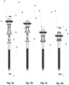
- FIGS. 2a to 2d show different assembly phases when assembling an adjusting screw arrangement 20 according to the invention.
- Fig. 2a shows the adjusting screw arrangement 20 according to the invention in a side view before assembly.
- the adjusting screw arrangement 20 comprises an adjusting screw 22 and a drive wheel 24, via which the adjusting screw 22 can be set in rotation. Furthermore, the adjusting screw arrangement 20 has a transmitter element 26 which transmits the rotational movement from the drive wheel 24 to the adjusting screw 22.
- the adjusting screw 22 has a connection area A1, so that the transmitter element 26, which is pushed onto the adjusting screw 22, engages behind the adjusting screw 22 in the connection area A1 in the assembled state.
- the transmitter element 26 has a correspondingly designed connection area A2.
- the drive wheel 24 and the transmitter element 26 are coordinated with one another in such a way that the drive wheel 24 can be pushed over the transmitter element 26, so that, in the assembled state, the transmitter element 26 produces a positive connection with the adjusting screw 22 that acts in the axial direction and the transmitter element 26 and that Drive wheel 24 are fixed axially to one another via a locking connection.
- the adjusting screw assembly 20 comprises three components that are assembled for operation.
- Fig. 2b shows that for optimal assembly, the drive wheel 24 is first partially pushed onto the transmitter element 26, so that there is a slight preload for the expansion elements of the transmitter element 26.
- Fig. 3 shows the detailed section view Fig. 2a , where the 4a to 4c show enlarged views of the components adjusting screw 22, transmitter element 26 and drive wheel 24.
- connection area A1 of the adjusting screw 22 and the connection area A2 of the transmitter element 26 are coordinated with one another in such a way that molded parts 30 of the transmitter element 26 can engage behind a retaining structure 32 of the adjusting screw.
- the retaining structure is preferably designed as an annular shoulder.
- the transmitter element 26 has positive-locking contours 28b and the adjusting screw 22 has positive-locking contours 28a, which mesh with one another to transmit the rotary movement between the transmitter element 26 and the adjusting screw 22.
- the transmitter element 26 and the adjusting screw 22 are coordinated with one another in such a way that the form-fitting contours 28a, 28b engage one another when the molded parts 30 of the transmitter element 26 engage behind the retaining structure 32 of the adjusting screw 22.
- the transmitter element 26 is designed in the form of an expansion sleeve which comprises individual expansion elements 34 which end together in a head part.
- a, in particular essentially conical, grid elevation 36 which enables locking with the drive wheel 24.
- the drive wheel 24 has locking fingers 38 designed to correspond to the grid elevation 36, which are spread apart in the unloaded case in order to then be applied to the adjusting screw 22 by pushing the drive wheel 24 over the transmitter element 26.
- the drive wheel 24 has positive locking structures 40b, which in the assembled state are in engagement with positive locking structures 40a of the transmitter element 26, whereby a rotational movement can be transmitted from the drive wheel 24 to the transmitter element 26.
- Fig.5 shows a detailed sectional view of the adjusting screw arrangement 20 according to Fig. 2d in assembled condition.
- the transmitter element 26 is fixed to the adjusting screw 22 by the drive wheel 24.
- the drive wheel 24 has teeth 46 and is designed like a sleeve and has a hollow cylindrical region 44. It encloses the expansion elements 34 of the transmitter element 26 in a form-fitting manner.
- the molded parts 30, which engage behind the retaining structure 32 of the adjusting screw, are held in position, as a result of which the transmitter element 26 is also fixed to the adjusting screw 22 in a form-fitting manner in the axial direction.
- a locking connection 36, 38 is provided to fix the drive wheel 24 relative to the transmitter element 26 in the axial direction.
- the drive wheel 24 is raised over the grid elevation 36 pushed, with the locking fingers 38 located on the drive wheel 24 spreading apart and then locking with it after overcoming the grid elevation 36.
- both the drive wheel 24 and the transmitter element 26 are plastic parts, the shape of the geometry of the locking fingers 38 and the locking elevation 36 can be determined relatively freely and adjusted to achieve low assembly forces despite high pull-off forces.
- the drive wheel 24 includes in its hollow cylindrical region 44 a groove 42 in which a seal, in particular an O-ring, can be received in order to seal the drive wheel from the housing of the adjusting device.
- a seal in particular an O-ring
- Fig. 6a shows a side view and Fig. 6b a sectional view of a transmitter element 26 and a drive wheel 24 of a particularly preferred embodiment of an adjusting screw arrangement 20 according to the invention.
- the adjustment screw 22 is not shown in this figure, since it corresponds to the adjusting screw 22 in form and function of the adjusting screw 22, as described above.
- the drive wheel 24 has teeth 46 and an adjoining hollow cylindrical region 44.
- a groove 42 is made in the hollow cylindrical region 46.
- An O-ring 48 is received in the groove 42, via which the drive wheel 24 is sealed against the housing of the adjusting device.
- the locking fingers 38 are attached to the side of the toothing 46 opposite the hollow cylindrical region 44.
- the transmitter element 26 is designed as an expansion sleeve and has expansion elements 34, which can be fixed in a form-fitting manner via the drive wheel 24 on the adjusting screw 22, as described above.
- the expansion elements 34 are provided with positive locking contours 40b to engage with the positive locking contours 40a of the drive wheel 24 to transmit rotational movement between these parts.
- the expansion elements 34 merge into a head part 50.
- the head part forms a closed sleeve, which is also closed at the front.
- the form-fitting contours 28b are introduced in the front area of the sleeve.
- the design according to the Fig. 6a, Fig. 6b differs from the design according to Fig. 2 to 5 in that the transmitter element has a rib 52 on the head part 50.
- the head part 50 is designed to be completely closed beyond the rib 52 in the direction of the front drive.
- notches 54 are provided in the head part for receiving the locking fingers 38.
- the locking fingers can also transmit a torque in addition to locking with the grid elevation 36. This allows the transferable torque to be increased.
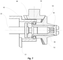
- Fig. 7 shows a set screw arrangement 20 according to Fig. 6a, 6b in a schematically shown storage in a housing 12 of an adjusting device according to the invention. Essentially the differences to the execution are shown Fig. 5 described.
- the drive wheel 24 includes a groove 42 in which an O-ring 48 is received.
- the transmitter element 26, whose expansion elements 34 are held in a form-fitting manner by the drive wheel 24, has a circumferential rib 52 on the outer circumference of its closed head part 50. This rib 52 seals the transmitter element 26, which, like the rib 52, is also made of plastic, against the drive wheel 24. Since the head part 50 is designed to be closed at least from the rib 52 to the head end, as a result no liquid can get from the adjusting screw 22 to the side of the housing on which the teeth of the drive wheel 46 lie.
- an adjusting device is therefore created which ensures a high degree of tightness with low assembly forces and a small installation space.
Landscapes
- Engineering & Computer Science (AREA)
- Mechanical Engineering (AREA)
- Lighting Device Outwards From Vehicle And Optical Signal (AREA)
- Transmission Devices (AREA)
Description
- Die Erfindung betrifft eine Einstellvorrichtung für einen Scheinwerfer gemäß dem Oberbegriff des Anspruchs 1.
- Gattungsgemäße Einstelleinrichtungen für einen Scheinwerfer eines Kraftfahrzeuges werden in einem Fahrzeug verwendet, um eine Einstellung der Scheinwerfer nach Fertigstellung des Fahrzeugs zu ermöglichen.
- Die
DE 10 2010 0617 428 A1 - Ferner ist ein Übertragungsteil vorgesehen, das das Kegelrad formschlüssig mit der Stellschraube drehfest koppelt. Durch das Übertragungsteil kann so nach erfolgter erstmaliger Einstellung auch eine einfache bedarfsgemäße Entkopplung erfolgen, so dass später im Betrieb keine unbeabsichtigte Verstellung eintritt.
- Die
DE 10 2010 061 437 A1 offenbart eine Einstellvorrichtung mit einer Stellschraube, die drehfest mit einem Antriebsrad in Umfangsrichtung formschlüssig im Eingriff steht und in Axialrichtung über ein Rastverbindung mit einer Gegenhaltestruktur eingerastet ist. - In den genannten Anwendungen wird eine axiale Rastverbindung unmittelbar zwischen Antriebsrad und Stellschraube hergestellt.
- Die
WO 2013 / 064164 A1 offenbart eine Einstellvorrichtung für einen Scheinwerfer, bei welcher eine Stellspindel mit einem Dichtungsflansch versehen ist. Die Stellspindel wird durch ein Gehäuse gesteckt und an ihrem rückseitigen Ende mit einer Anordnung verbunden, bei der ein Übertragerlement und ein Antriebszahnrad über das das Gehäuse durchsetzende Stellspindelende geschoben und mit diesem verbunden wird. Dies erlaubt eine Montage mit geringem Kraftaufwand. - Es ist Aufgabe der Erfindung eine Einstellvorrichtung zur Scheinwerferverstellung anzugeben, bei der niedrige Montagekräfte bei möglichst geringem Bauraum erzielt werden und eine einfache Abdichtung zwischen Stellschraube und Antriebsrad über das Gehäuse erreicht werden kann, bei der das Verstellmoment für die Stellschraube in engen Grenzen gehalten werden kann.
- Die Aufgabe wird durch die kennzeichnenden Merkmale des Anspruchs 1 gelöst.
- Die Unteransprüche bilden vorteilhafte Weiterbildungen der Erfindung.
- Eine Einstellvorrichtung für einen Scheinwerfer umfasst in bekannter Weise eine Stellschraubenanordnung, umfassend eine Stellschraube und ein Antriebsrad über das die Stellschraube in Drehung versetzbar ist. Ferner weist die Stellschraubenanordnung ein Übertragerelement auf, das die Drehbewegung von dem Antriebsrad auf die Stellschraube überträgt. So weisen das Übertragerelement und die Stellschraube ineinandergreifende Formschlusskonturen zur Übertragung der Drehbewegung zwischen Übertragerelement und Stellschraube auf. Zudem weist das Antriebsrad und das Übertragerelement Formschlussstrukturen auf, über die eine Drehbewegung vom Antriebsrad auf das Übertragerelement übertragen werden kann.
- Weiter bekannt ist, dass die Stellschraube einen Anschlussbereich aufweist, so dass das Übertragerelement, das auf die Stellschraube aufgeschoben werden kann, im zusammengebauten Zustand, die Stellschraube im Anschlussbereich hintergreifen kann. Das Antriebsrad und das Übertragerelement sind derart aufeinander abgestimmt, dass das Antriebsrad über das Übertragerelement geschoben werden kann, so dass, im zusammengebauten Zustand, das Übertragerelement mit der Stellschraube einen in Axialrichtung wirkenden Formschluss herstellt und das Übertragerelement und das Antriebsrad über eine Rastverbindung axial zueinander festgelegt sind.
- Erfindungsgemäß ist vorgesehen, dass das Antriebsrad einen hohlzylindrischen Bereich umfasst, in den am äußeren Umfang eine Ringnut zur Aufnahme einer Dichtung, insbesondere einer O-Ring-Dichtung, eingebracht ist.
- Durch die Einbringung der Ringnut in den hohlzylindrischen Teil des Antriebsrads, über den die Stellschraubenanordnung im Gehäuse gelagert ist und gegenüber diesem abgedichtet ist, kann eine Radialdichtung zwischen zwei Kunststoffteilen erfolgen.
- Diese Anordnung ist besonders vorteilhaft, da durch die Verwendung von Kunststoff die Normwerte für gängige O-Ringe zuverlässig eingehalten werden können, insbesondere im Hinblick auf axiale Toleranzen. So kann bevorzugt in die Ringnut eine Dichtung, insbesondere eine O-Ring-Dichtung eingesetzt sein.
- Gemäß einer weiteren, besonders vorteilhaften Weiterbildung kann das Übertragerelement einen hohlzylindrischen Bereich, insbesondere ein Kopfteil umfassen, an dem eine umlaufende Rippe angeordnet ist. Dies ermöglicht eine zuverlässige Abdichtung gegenüber dem Antriebsrad. Das Kopfteil des Übertragerelements ist ausgehend von der umlaufenden Rippe zum antriebsradseitige Ende als einseitig geschlossene Hülse ausgebildet, so dass, ggfs. zwischen der Stellschraube und dem Übertragerelement eindringendes, Wasser nicht auf die Antriebsradseite der Einstelleinrichtung gelangen kann.
- Auf diese Weise kann durch die erfindungsgemäße Anordnung eine zuverlässige Dichtung realisiert werden, da ausschließlich Dichtungen zwischen Kunststoffteilen notwendig sind.
- Die erfindungsgemäße Anordnung legt so das Übertragerelement an der Stellschraube fest, wobei die Rastverbindung, die letztendlich die axiale Position zwischen Stellschraube und Antriebsrad festlegt, zwischen dem Übertragerelement und dem Antriebsrad hergestellt wird.
- Dies hat den Vorteil, dass die Stellschraube aus Stahl hergestellt sein kann, das Übertragerelement und das Antriebsrad aus Kunststoff, so dass durch die Kunststoff/Kunststoff-Rastverbindung verbesserte Verbindungseigenschaften gegenüber einer Stahl/Kunststoff Verbindung erzielt werden können. Insbesondere können die Geometrien derart aufeinander abgestimmt werden, dass geringe Montagekräfte bei hohen Auszugskräften vorliegen.
- Gemäß einer Weiterbildung der Erfindung sind die Formschlusskonturen zur Übertragung der Drehbewegung am von dem Gewinde abgelegenen Ende der Stellschraube angeordnet. Dies hat den Vorteil, dass das Stellschraubenende in Form eines Außenantriebs und das Übertragerelement in Form eines Innenantriebs gestaltet werden kann. Dadurch kann auch eine axiale Arretierung des Übertragerelements in Richtung des Gewindes der Stellschraube erreicht werden.
- Gemäß einer weiteren bevorzugten Ausgestaltung sind das Antriebsrad und das Übertragerelement ausgebildet, um an dem Ende, das dem gewindetragenden Teil der Stellschraube zugewandt ist, zur Übertragung einer Drehbewegung ineinanderzugreifen. Dadurch kann durch die Formschlussstrukturen gleichzeitig eine axiale Arretierung des Antriebsrads gegenüber der Stellschraube in Richtung des Gewindes der Stellschraube erreicht werden.
- In besonders vorteilhafter Weise kann der Anschlussbereich der Stellschraube eine Ringschulter aufweisen. Dies lässt sich insbesondere unter Verwendung einer Stellschraube aus Stahl gut herstellen. Der Anschlussbereich des Übertragerelements weist dazu korrespondierende Formteile auf, die die Ringschulter hintergreifen können. Auf diese Weise kann ein in Axialrichtung formschlüssiges Festlegen des Übertragerelements an der Stellschraube erfolgen, wenn die Formteile formschlüssig in der hintergriffenen Position gehalten werden.
- Um die Formteile formschlüssig in der hintergriffenen Position zu halten, kann das Übertragerelement in bevorzugter Weise im Anschlussbereich eine Spreizhülse aufweisen, die Spreizelemente umfasst, die zur Ringschulter korrespondierende Formteile aufweisen. Die Formteile können sich auch dadurch ergeben, dass eine Rille im Spreizelement der Spreizhülse ausgenommen ist.
- Zur formschlüssigen Festlegung der Formteile des Übertragerelements an der Stellschraube kann das Antriebsrad einen Innendurchmesser aufweisen, der in etwa dem Außendurchmesser der Spreizhülse im eingebauten, nicht gespreizten Zustand entspricht. Auf diese Weise wird ein Aufspreizen der Spreizelemente bei axialem Zug zuverlässig verhindert. So kann letztendlich das Übertragerelement formschlüssig an der Stellschraube gehalten werden.
- Der Anschlussbereich liegt, in Axialrichtung gesehen, bevorzugt zwischen den Formschlusskonturen zur Übertragung der Drehbewegung zwischen Übertragerelement und Stellschraube und den Formschlussstrukturen zur Übertragung einer Drehbewegung vom Antriebsrad auf das
- Übertragerelement. So können die unterschiedlichen Bereiche der Stellschraubenanordnung explizit ausschließlich ihrer zugeordneten Funktionen gemäß gestaltet werden.
- Weiter bevorzugt weisen das Antriebsrad und / oder das Übertragerelement Rastmittel auf, so dass sich bei einem auf das Übertragerelement aufgesteckten Antriebsrad eine axiale Festlegung des Antriebsrads am Übertragerelement, insbesondere in Axialrichtung entgegen dem Gewinde der Stellschraube ergibt. Die Rastmittel sind bevorzugt so aufeinander abgestimmt, dass möglichst geringe Montagekräfte bei der Verrastung entstehen und dennoch eine hohe Abzugskraft gewährleistet ist.
- Weitere Vorteile, Merkmale und Anwendungsmöglichkeiten der vorliegenden Erfindung ergeben sich aus der nachfolgenden Beschreibung in Verbindung mit den in den Zeichnungen dargestellten Ausführungsbeispielen.
- In der Beschreibung, in den Ansprüchen und in der Zeichnung werden die in der unten aufgeführten Liste der Bezugszeichen verwendeten Begriffe und zugeordneten Bezugszeichen verwendet. In der Zeichnung bedeutet:
- Fig. 1
- eine erfindungsgemäße Einstellvorrichtung;
- Fig. 2a
- eine Seitenansicht einer Stellschraubenanordnung vor dem Zusammenbau;
- Fig. 2b
- eine Seitenansicht einer Stellschraubenanordnung in einem ersten Montageschritt;
- Fig. 2c
- eine Seitenansicht einer Stellschraubenanordnung in einem zweiten Montageschritt;
- Fig. 2d
- eine Seitenansicht einer Stellschraubenanordnung im zusammengebauten Zustand;
- Fig. 3
- eine Schnittansicht der Stellschraubenanordnung gemäß
Fig. 2a ; - Fig. 4a
- eine Seitenansicht der Stellschraube;
- Fig. 4b
- eine Schnittansicht des Übertragerelements;
- Fig. 4c
- eine Schnittansicht des Antriebsrads;
- Fig. 5
- eine Schnittansicht der Stellschraubenanordnung gemäß
Fig. 2d ; - Fig. 6a
- eine Seitenansicht einer Kombination einer weiteren Ausführung aus Antriebsrad und Übertragerelement, und
- Fig. 6b
- eine Schnittansicht der Kombination aus
Fig. 6a . - Fig. 7
- eine Detail-Schnittansicht einer Einstelleinrichtung mit einer Kombination gemäß
Fig. 6a . -
Fig. 1 zeigt eine Einstellvorrichtung 10 für einen Scheinwerfer (nicht gezeigt). Die Einstellvorrichtung umfasst in bekannter Weise eine Stellschraubenanordnung 20, die in einem Gehäuse 12 drehbar gelagert ist und von einem Kegelrad 14 angetrieben wird. Der Scheinwerfer wird über einen mit der Stellschraubenanordnung 20 verbundenen, im Gehäuse 12 lineargeführten Stellblock 16 eingestellt. Das Kegelrad 14 treibt ein Antriebsrad 24 der Stellschraubenanordnung 20 an, um diese in Drehung zu versetzen. - Im Folgenden wird die erfindungsgemäße Stellschraubenanordnung 20 der Einstellvorrichtung 10 näher beschrieben.
- Die
Figuren 2a bis 2d zeigen verschiedene Montagephasen beim Zusammenbau einer erfindungsgemäßen Stellschraubenanordnung 20. -
Fig. 2a zeigt die erfindungsgemäße Stellschraubenanordnung 20 in einer Seitenansicht vor der Montage. Die Stellschraubenanordnung 20 umfasst eine Stellschraube 22, und ein Antriebsrad 24, über das die Stellschraube 22 in Drehung versetzbar ist. Ferner weist die Stellschraubenanordnung 20 ein Übertragerelement 26 auf, das die Drehbewegung von dem Antriebsrad 24 auf die Stellschraube 22 überträgt. - Erfindungsgemäß ist vorgesehen, dass die Stellschraube 22 einen Anschlussbereich A1 aufweist, so dass das Übertragerelement 26, das auf die Stellschraube 22 aufgeschoben wird, im zusammengebauten Zustand, die Stellschraube 22 im Anschlussbereich A1 hintergreift. Das Übertragerelement 26 weist dazu einen korrespondierend ausgestalteten Anschlussbereich A2 auf.
- Das Antriebsrad 24 und das Übertragerelement 26 sind derart aufeinander abgestimmt, dass das Antriebsrad 24 über das Übertragerelement 26 geschoben werden kann, so dass, im zusammengebauten Zustand, das Übertragerelement 26 mit der Stellschraube 22 einen in Axialrichtung wirkenden Formschluss herstellt und das Übertragerelement 26 und das Antriebsrad 24 über eine Rastverbindung axial zueinander festgelegt sind.
- So umfasst die erfindungsgemäße Stellschraubenanordnung 20 drei Komponenten, die für den Betrieb montiert werden.
- Die Gestaltung der Komponenten, nämlich Stellschraube 22, Übertragerelement 26 und Antriebsrad 24, ist in den
Figuren 3 bis 4c näher beschrieben. -
Fig. 2b zeigt, dass für eine optimale Montage zuerst das Antriebsrad 24 teilweise auf das Übertragerelement 26 aufgeschoben wird, so dass sich eine leichte Vorspannung für Spreizelemente des Übertragerelements 26 ergibt. - Dann kann gemäß
Fig. 2c ein Aufschieben der Kombination aus Antriebsrad und Übertragerelement 26 erfolgen, und das Übertragerelement 26 kann so ausgerichtet werden, dass die Formschlussstrukturen zur Drehübertragung ineinandergreifen, wobei die Kombination gegenüber der Stellschraube 22 vorfixiert wird, sobald die Kombination und die Stellschraube ineinandergreifen. - Wie
Fig. 2d zeigt wird zur endgültigen Montage das Antriebsrad 24 vollständig auf das Übertragerelement 26 aufgeschoben. Dieses ist nun sowohl drehfest als auch in Axialrichtung gegenüber der Stellschraube 22 fixiert, wodurch die Stellschraubenanordnung 20 betriebsbereit ist und in der Einstellvorrichtung 10 verbaut werden kann. -
Fig. 3 zeigt die Detailschnittansicht zuFig. 2a , wobei dieFig. 4a bis 4c vergrößerte Ansichten der Komponenten Stellschraube 22, Übertragerelement 26 und Antriebsrad 24 zeigen. - Der Anschlussbereich A1 der Stellschraube 22, und der Anschlussbereich A2 des Übertragerelements 26 sind so aufeinander abgestimmt, dass Formteile 30 des Übertragerelements 26 eine Rückhaltestruktur 32 der Stellschraube hintergreifen können. Die Rückhaltestruktur ist bevorzugt als Ringschulter ausgebildet.
- Ferner weist das Übertragerelement 26 Formschlusskonturen 28b und die Stellschraube 22 Formschlusskonturen 28a auf, die zur Übertragung der Drehbewegung zwischen Übertragerelement 26 und Stellschraube 22 ineinandergreifen. Das Übertragerelement 26 und die Stellschraube 22 sind so aufeinander abgestimmt, dass die Formschlusskonturen 28a, 28b ineinandergreifen, wenn die Formteile 30 des Übertragerelements 26 die Rückhaltestruktur 32 der Stellschraube 22 hintergreifen.
- Das Übertragerelement 26 ist in Form einer Spreizhülse ausgebildet, die einzelne Spreizelemente 34 umfasst, die gemeinsam in einem Kopfteil enden.
- Am Ende des Kopfteils ist eine, insbesondere im Wesentlichen konische, Rasterhebung 36 angeordnet, die ein Verrasten mit dem Antriebsrad 24 ermöglicht. Das Antriebsrad 24 weist dazu korrespondierend zu der Rasterhebung 36 ausgebildete Rastfinger 38 auf, die im unbelasteten Fall aufgespreizt sind, um dann an die Stellschraube 22 angelegt zu werden, indem das Antriebsrad 24 über das Übertragerelement 26 geschoben wird.
- Zudem weist das Antriebsrad 24 Formschlussstrukturen 40b auf, die im zusammengebauten Zustand in Eingriff mit Formschlussstrukturen 40a des Übertragerelements 26 sind, wodurch eine Drehbewegung vom Antriebsrad 24 auf das Übertragerelement 26 übertragen werden kann.
-
Fig.5 zeigt eine Detail-Schnittansicht der Stellschraubenanordnung 20 gemäßFig. 2d im zusammengebauten Zustand. - Bei der erfindungsgemäßen Stellschraubenanordnung 20 wird das Übertragerelement 26 an der Stellschraube 22 durch das Antriebsrad 24 festgelegt. Das Antriebsrad 24 weist eine Verzahnung 46 auf und ist hülsenartig ausgebildet und weist einen hohlzylindrischen Bereich 44 auf. Es umschließt die Spreizelemente 34 des Übertragerelements 26 formschlüssig. Dadurch werden die Formteile 30, die die Rückhaltestruktur 32 der Stellschraube hintergreifen, in Position gehalten, wodurch das Übertragerelement 26 auch in Axialrichtung formschlüssig an der Stellschraube 22 festgelegt ist. Gleichzeitig greifen die Formschlussstrukturen 40a, 40b zur Übertragung der Drehbewegung vom Antriebsrad 24 auf das Übertragerelement 26, sowie die Formschlussstrukturen 28a, 28b zur Übertragung der Drehbewegung vom Übertragerelement 26 auf die Stelleschraube 22, ineinander.
- Zur Fixierung des Antriebsrads 24 gegenüber dem Übertragerelement 26 in Axialrichtung ist eine Rastverbindung 36, 38 vorgesehen. Bei der Montage wird das Antriebsrad 24 über die Rasterhebung 36 geschoben, wobei sich am Antriebsrad 24 befindliche Rastfinger 38 aufspreizen und dann nach Überwinden der Rasterhebung 36 mit dieser verrasten.
- Die Geometrie der Rastfinger 38 und der Rasterhebung 36 kann aufgrund der Tatsache, dass es sich sowohl bei dem Antriebsrad 24 als auch bei dem Übertragerelement 26 um Kunststoffteile handelt, in ihrer Form relativ frei bestimmt und zur Erreichung geringer Montagekräfte trotz hoher Abzugskräfte angepasst werden.
- Ferner umfasst das Antriebsrad 24 in seinem hohlzylindrischen Bereich 44 eine Nut 42, in der eine Dichtung, insbesondere ein O-Ring aufgenommen werden kann, um das Antriebsrad gegenüber dem Gehäuse der Einstelleinrichtung abzudichten.
-
Fig. 6a zeigt eine Seitenansicht undFig. 6b eine Schnittansicht eines Übertragerelements 26 und ein Antriebsrad 24 einer besonders bevorzugten Ausgestaltung einer erfindungsgemäßen Stellschraubenanordnung 20. Auf die Darstellung der Stellschraube 22 wird in dieser Figur verzichtet, da diese der Stellschraube 22 in Form und Funktion der Stellschraube 22, wie zuvor beschrieben entspricht. - Das Antriebsrad 24 weist eine Verzahnung 46 und einen daran anschließenden hohlzylindrischen Bereich 44 auf. In dem hohlzylindrischen Bereich 46 ist eine Nut 42 eingebracht. In der Nut 42 ist ein O-Ring 48 aufgenommen über den das Antriebsrad 24 gegen das Gehäuse der Einstelleinrichtung abgedichtet wird.
- Die Rastfinger 38 sind am der dem hohlzylindrischen Bereich 44 gegenüberliegenden Seite der Verzahnung 46 angebracht.
- Das Übertragerelement 26 ist als Spreizhülse ausgebildet und weist Spreizelemente 34 auf, die über das Antriebsrad 24 an der Stellschraube 22, wie zuvor beschrieben formschlüssig festlegbar sind.
- Die Spreizelemente 34 sind mit Formschlusskonturen 40b versehen, um mit den Formschlusskonturen 40a des Antriebsrads 24 in Eingriff zu gelangen, um eine Drehbewegung zwischen diesen Teilen zu übertragen.
- Die Spreizelemente 34 gehen in ein Kopfteil 50 über. Das Kopfteil bildet eine geschlossene Hülse, die auch stirnseitig abgeschlossen ist. Im stirnseitigen Bereich der Hülse sind die Formschlusskonturen 28b eingebracht.
- Die Ausgestaltung gemäß der
Fig. 6a, Fig. 6b unterscheidet sich von der Ausgestaltung gemäßFig. 2 bis 5 dadurch, dass das Übertragerelement eine Rippe 52 am Kopfteil 50 aufweist. Das Kopfteil 50 ist jenseits der Rippe 52 in Richtung des stirnseitigen Antriebs vollständig geschlossen ausgebildet. - Ferner sind in dieser Ausgestaltung im Kopfteil 50 Einkerbungen 54 zur Aufnahme der Rastfinger 38 vorgesehen. Auf diese Weise können die Rastfinger neben der Verrastung mit der Rasterhebung 36 auch ein Drehmoment übertragen. Dadurch kann das übertragbare Drehmoment erhöht werden.
-
Fig. 7 zeigt eine Stellschraubenanordnung 20 gemäß denFig. 6a, 6b in einer schematisch dargestellten Lagerung in einem Gehäuse 12 einer erfindungsgemäßen Einstelleinrichtung. Es werden im Wesentlichen die Unterschiede zur Ausführung gemäßFig. 5 beschrieben. - Das Antriebsrad 24 umfasst eine Nut 42 in der ein O-Ring 48 aufgenommen ist. Durch die Ausbildung des Antriebsrads 24 aus Kunststoff, können die erforderlichen Axialtoleranzen zuverlässig eingehalten werden, so dass eine zuverlässige Dichtung zwischen dem Gehäuse 12 und dem Antriebsrad 24 vorliegt. Das Übertragerelement 26, dessen Spreizelemente 34 durch das Antriebsrad 24 formschlüssig gehalten werden, weist am äußeren Umfang seines geschlossenen Kopfteils 50 eine umlaufende Rippe 52 auf. Diese Rippe 52 dichtet das Übertragerelement 26, das wie die Rippe 52 ebenfalls aus Kunststoff gebildet ist, gegen das Antriebsrad 24 ab. Da das Kopfteil 50 wenigstens ab der Rippe 52 bis zum Kopfende geschlossen ausgeführt ist, kann im Ergebnis keine Flüssigkeit von der Stellschraube 22 auf die Seite des Gehäuses gelangen auf der die Verzahnung des Antriebsrads 46 liegt.
- Erfindungsgemäß ist daher eine Einstelleinrichtung geschaffen, die bei niedrigen Montagekräften bei geringem Bauraum ein hohes Maß an Dichtigkeit gewährleistet.
Claims (10)
- Einstellvorrichtung (10) für einen Scheinwerfer umfassend eine Stellschraubenanordnung (20) umfassend eine Stellschraube (22), ein Antriebsrad (24), über das die Stellschraube (22) in Drehung versetzbar ist und ein Übertragerelement (26), das die Drehbewegung von dem Antriebsrad (24) auf die Stellschraube (22) überträgt, wobei das Übertragerelement (26) und die Stellschraube (22) ineinandergreifende Formschlusskonturen (28a, 28b) zur Übertragung der Drehbewegung zwischen Übertragelement (26) und Stellschraube (22) aufweisen, wobei das Übertragerelement (26) und das Antriebsrad (24) Formschlussstrukturen (40a, 40b) aufweisen, über die eine Drehbewegung vom Antriebsrad (24) auf das Übertragerelement (26) übertragen werden kann, wobei die Stellschraube (22) einen Anschlussbereich (A1) aufweist, so dass das Übertragerelement (26), das auf die Stellschraube (22) aufgeschoben werden kann, im zusammengebauten Zustand, die Stellschraube (22) im Anschlussbereich (A1) hintergreift und einen in Axialrichtung wirkenden Formschluss herstellt, wobei ferner das Antriebsrad (24) über das Übertragerelement (26) geschoben werden kann, so dass, im zusammengebauten Zustand, der Anschlussbereich (A2) des Übertragerelements (26) am Anschlussbereich (A1) der Stellschraube (22) festgelegt ist, wobei das Übertragerelement (26) und das Antriebsrad (24) über eine Rastverbindung (36, 38) axial zueinander festgelegt werden, dadurch gekennzeichnet, dass das Antriebsrad einen hohlzylindrischen Bereich (44), zur Lagerung der Stellschraubenanordnung in einem Gehäuse, umfasst, in den am äußeren Umfang eine Ringnut (42) zur Aufnahme einer Dichtung eingebracht ist, um das Antriebsrad gegenüber dem Gehäuse abzudichten.
- Einstellvorrichtung nach Anspruch 1, dadurch gekennzeichnet, dass in der Ringnut (42) ein Dichtungselement, insbesondere ein O-Ring (48), aufgenommen ist.
- Einstellvorrichtung nach Anspruch 1 oder 2, dadurch gekennzeichnet, dass das Übertragerelement (26) ein geschlossenes Kopfteil (50) umfasst, an dem eine umlaufende Rippe (52) angeordnet ist.
- Einstellvorrichtung nach einem der vorangehenden Ansprüche, dadurch gekennzeichnet, dass die Stellschraube (22) aus Metall, das Antriebsrad (24) und das Übertragerelement (26) aus Kunststoff hergestellt ist.
- Einstellvorrichtung nach einem der vorangehenden Ansprüche, dadurch gekennzeichnet, dass die Formschlusskonturen (28a, 28b) zur Übertragung der Drehbewegung am von dem Gewinde abgelegenen Ende der Stellschraube (22) angeordnet sind.
- Einstellvorrichtung nach einem der vorangehenden Ansprüche, dadurch gekennzeichnet, dass der Anschlussbereich (A1) der Stellschraube (22) eine Rückhaltestruktur (32), insbesondere in Form einer Ringschulter, aufweist, und der Anschlussbereich (A2) des Übertragerelements korrespondierende Formteile (30) aufweist, die die Rückhaltestruktur (32) hintergreifen.
- Einstellvorrichtung nach Anspruch 6, dadurch gekennzeichnet, dass das Übertragerelement (26) als eine Spreizhülse ausgebildet ist, die im Anschlussbereich (A2) Spreizelemente (34) aufweist, welche zur Rückhaltestruktur korrespondierende Formteile (30) aufweisen.
- Einstellvorrichtung nach einem der vorangehenden Ansprüche, dadurch gekennzeichnet, dass das Antriebsrad (24) einen Innendurchmesser aufweist, der in etwa dem Außendurchmesser der Spreizhülse im Anschlussbereich (A1) im eingebauten Zustand entspricht.
- Einstellvorrichtung nach Anspruch 8, dadurch gekennzeichnet, dass das Antriebsrad (24) und / oder das Übertragerelement (26) Rastmittel (36, 38) aufweist, so dass sich bei einem auf das Übertragerelement (26) aufgestecktem Antriebsrad (24) eine axiale Festlegung des Antriebsrads (24) am Übertragerelement (26) ergibt.
- Einstellvorrichtung nach einem der vorangehenden Ansprüche, dadurch gekennzeichnet, dass das Antriebsrad (24) und das Übertragerelement (26) an dem dem gewindetragenden Teil der Stellschraube (22) zugewandten Ende Formschlussstrukturen (40a, 40b) aufweisen, die zur Übertragung einer Drehbewegung ineinandergreifen.
Applications Claiming Priority (2)
| Application Number | Priority Date | Filing Date | Title |
|---|---|---|---|
| DE102019127345.5A DE102019127345A1 (de) | 2019-10-10 | 2019-10-10 | Einstellvorrichtung für einen Scheinwerfer |
| PCT/EP2020/078630 WO2021069744A1 (de) | 2019-10-10 | 2020-10-12 | Einstellvorrichtung für einen scheinwerfer |
Publications (3)
| Publication Number | Publication Date |
|---|---|
| EP4041597A1 EP4041597A1 (de) | 2022-08-17 |
| EP4041597B1 true EP4041597B1 (de) | 2023-09-27 |
| EP4041597C0 EP4041597C0 (de) | 2023-09-27 |
Family
ID=73014474
Family Applications (1)
| Application Number | Title | Priority Date | Filing Date |
|---|---|---|---|
| EP20797045.0A Active EP4041597B1 (de) | 2019-10-10 | 2020-10-12 | Einstellvorrichtung für einen scheinwerfer |
Country Status (3)
| Country | Link |
|---|---|
| EP (1) | EP4041597B1 (de) |
| DE (1) | DE102019127345A1 (de) |
| WO (1) | WO2021069744A1 (de) |
Cited By (1)
| Publication number | Priority date | Publication date | Assignee | Title |
|---|---|---|---|---|
| DE102023118361A1 (de) * | 2023-07-11 | 2025-01-16 | Ejot Se & Co. Kg | Fixiereinheit und Stellschraubenanordnung |
Families Citing this family (1)
| Publication number | Priority date | Publication date | Assignee | Title |
|---|---|---|---|---|
| DE102022127959A1 (de) | 2022-10-21 | 2024-05-02 | Ejot Se & Co. Kg | Einstellvorrichtung |
Family Cites Families (7)
| Publication number | Priority date | Publication date | Assignee | Title |
|---|---|---|---|---|
| JP2768859B2 (ja) * | 1991-11-26 | 1998-06-25 | 株式会社小糸製作所 | 車輌用灯具におけるエイミングスクリュー支承構造 |
| FR2719651B1 (fr) * | 1994-05-03 | 1996-07-26 | Valeo Vision | Dispositif de réglage et d'indication de l'orientation d'un réflecteur de projecteur de véhicule automobile. |
| JP3229554B2 (ja) * | 1995-10-02 | 2001-11-19 | 株式会社小糸製作所 | 車輌用前照灯 |
| JP3822007B2 (ja) * | 1999-10-21 | 2006-09-13 | 株式会社小糸製作所 | リフレクター可動型自動車用ヘッドランプ |
| DE102010061428A1 (de) * | 2010-12-21 | 2012-06-21 | Hella Kgaa Hueck & Co. | Einstellvorrichtung für Scheinwerfer |
| CN103906657B (zh) * | 2011-10-31 | 2016-07-20 | 黑拉许克联合股份有限公司 | 用于前照灯的调整装置 |
| DE102017122102B4 (de) * | 2017-09-25 | 2026-04-16 | HELLA GmbH & Co. KGaA | Einstelleinrichtung zur Einstellung der Lage wenigstens eines Lichtmoduls im Gehäuse eines Scheinwerfers |
-
2019
- 2019-10-10 DE DE102019127345.5A patent/DE102019127345A1/de not_active Withdrawn
-
2020
- 2020-10-12 WO PCT/EP2020/078630 patent/WO2021069744A1/de not_active Ceased
- 2020-10-12 EP EP20797045.0A patent/EP4041597B1/de active Active
Cited By (1)
| Publication number | Priority date | Publication date | Assignee | Title |
|---|---|---|---|---|
| DE102023118361A1 (de) * | 2023-07-11 | 2025-01-16 | Ejot Se & Co. Kg | Fixiereinheit und Stellschraubenanordnung |
Also Published As
| Publication number | Publication date |
|---|---|
| DE102019127345A1 (de) | 2021-04-15 |
| WO2021069744A1 (de) | 2021-04-15 |
| EP4041597A1 (de) | 2022-08-17 |
| EP4041597C0 (de) | 2023-09-27 |
Similar Documents
| Publication | Publication Date | Title |
|---|---|---|
| EP3345670B1 (de) | Filtereinrichtung | |
| EP3717786B1 (de) | Toleranzausgleichsanordnung mit klemmsicherung | |
| DE102020105716C5 (de) | Stellantrieb mit einer Drehmomentbegrenzungsvorrichtung | |
| DE102013006720A1 (de) | Verbindungselement sowie Verbindungsanordnung | |
| EP2012036A2 (de) | Arretierung | |
| EP3089284B1 (de) | Elektrischer winkelstecker mit stützring und verrastring einer gegenlagerung für ein federelement | |
| DE102018108829A1 (de) | Halteelement | |
| EP4041597B1 (de) | Einstellvorrichtung für einen scheinwerfer | |
| EP3495695B1 (de) | Getriebegehäuse für ein planetengetriebe | |
| EP2452419B1 (de) | Elektromotor mit anbaugehäuse | |
| WO2007124838A1 (de) | Lenkvorrichtung für fahrzeuge und verfahren zur montage einer lageranordnung | |
| DE4419180C2 (de) | Antrieb für ein bewegbares Fahrzeugteil | |
| EP2598746B1 (de) | Startvorrichtung für eine brennkraftmaschine | |
| DE102010019029B4 (de) | Betätigungsvorrichtung für eine Kraftfahrzeugsitzverstellung | |
| DE102019107888A1 (de) | Halteanordnung eines ersten Bauteils an einem zweiten Bauteil eines Kraftfahrzeugs sowie Verfahren zum Herstellen einer Halteanordnung | |
| EP1902192B1 (de) | Vorrichtung und verfahren zum verbinden einer getriebe-antriebseinheit mit einem karosserieteil eines kraftfahrzeugs | |
| DE102006031215B4 (de) | Seiltrommel für einen Kraftfahrzeugfensterheber | |
| WO2024084043A1 (de) | Einstellvorrichtung | |
| DE102005048528B3 (de) | Einrichtung und Verfahren zum Herstellen einer Verbindung zwischen zwei Abschnitten eines Koaxialrohres | |
| DE202021106813U1 (de) | Spannvorrichtung | |
| DE102019213843A1 (de) | Wellengeneratoranordnung und Spannungswellengetriebe | |
| WO2010130593A1 (de) | Anbindestruktur in einem kupplungsbetätigungslager und kupplungsbetätigungslager | |
| DE19824842A1 (de) | Freilaufanordnung |
Legal Events
| Date | Code | Title | Description |
|---|---|---|---|
| STAA | Information on the status of an ep patent application or granted ep patent |
Free format text: STATUS: UNKNOWN |
|
| STAA | Information on the status of an ep patent application or granted ep patent |
Free format text: STATUS: THE INTERNATIONAL PUBLICATION HAS BEEN MADE |
|
| PUAI | Public reference made under article 153(3) epc to a published international application that has entered the european phase |
Free format text: ORIGINAL CODE: 0009012 |
|
| STAA | Information on the status of an ep patent application or granted ep patent |
Free format text: STATUS: REQUEST FOR EXAMINATION WAS MADE |
|
| 17P | Request for examination filed |
Effective date: 20220429 |
|
| AK | Designated contracting states |
Kind code of ref document: A1 Designated state(s): AL AT BE BG CH CY CZ DE DK EE ES FI FR GB GR HR HU IE IS IT LI LT LU LV MC MK MT NL NO PL PT RO RS SE SI SK SM TR |
|
| DAV | Request for validation of the european patent (deleted) | ||
| DAX | Request for extension of the european patent (deleted) | ||
| GRAP | Despatch of communication of intention to grant a patent |
Free format text: ORIGINAL CODE: EPIDOSNIGR1 |
|
| STAA | Information on the status of an ep patent application or granted ep patent |
Free format text: STATUS: GRANT OF PATENT IS INTENDED |
|
| INTG | Intention to grant announced |
Effective date: 20230224 |
|
| GRAS | Grant fee paid |
Free format text: ORIGINAL CODE: EPIDOSNIGR3 |
|
| GRAJ | Information related to disapproval of communication of intention to grant by the applicant or resumption of examination proceedings by the epo deleted |
Free format text: ORIGINAL CODE: EPIDOSDIGR1 |
|
| GRAL | Information related to payment of fee for publishing/printing deleted |
Free format text: ORIGINAL CODE: EPIDOSDIGR3 |
|
| STAA | Information on the status of an ep patent application or granted ep patent |
Free format text: STATUS: REQUEST FOR EXAMINATION WAS MADE |
|
| GRAP | Despatch of communication of intention to grant a patent |
Free format text: ORIGINAL CODE: EPIDOSNIGR1 |
|
| STAA | Information on the status of an ep patent application or granted ep patent |
Free format text: STATUS: GRANT OF PATENT IS INTENDED |
|
| INTC | Intention to grant announced (deleted) | ||
| INTG | Intention to grant announced |
Effective date: 20230718 |
|
| GRAA | (expected) grant |
Free format text: ORIGINAL CODE: 0009210 |
|
| STAA | Information on the status of an ep patent application or granted ep patent |
Free format text: STATUS: THE PATENT HAS BEEN GRANTED |
|
| AK | Designated contracting states |
Kind code of ref document: B1 Designated state(s): AL AT BE BG CH CY CZ DE DK EE ES FI FR GB GR HR HU IE IS IT LI LT LU LV MC MK MT NL NO PL PT RO RS SE SI SK SM TR |
|
| REG | Reference to a national code |
Ref country code: GB Ref legal event code: FG4D Free format text: NOT ENGLISH |
|
| REG | Reference to a national code |
Ref country code: CH Ref legal event code: EP |
|
| REG | Reference to a national code |
Ref country code: DE Ref legal event code: R096 Ref document number: 502020005440 Country of ref document: DE |
|
| REG | Reference to a national code |
Ref country code: IE Ref legal event code: FG4D Free format text: LANGUAGE OF EP DOCUMENT: GERMAN |
|
| U01 | Request for unitary effect filed |
Effective date: 20231026 |
|
| U07 | Unitary effect registered |
Designated state(s): AT BE BG DE DK EE FI FR IT LT LU LV MT NL PT SE SI Effective date: 20231102 |
|
| PG25 | Lapsed in a contracting state [announced via postgrant information from national office to epo] |
Ref country code: GR Free format text: LAPSE BECAUSE OF FAILURE TO SUBMIT A TRANSLATION OF THE DESCRIPTION OR TO PAY THE FEE WITHIN THE PRESCRIBED TIME-LIMIT Effective date: 20231228 |
|
| PG25 | Lapsed in a contracting state [announced via postgrant information from national office to epo] |
Ref country code: RS Free format text: LAPSE BECAUSE OF FAILURE TO SUBMIT A TRANSLATION OF THE DESCRIPTION OR TO PAY THE FEE WITHIN THE PRESCRIBED TIME-LIMIT Effective date: 20230927 Ref country code: NO Free format text: LAPSE BECAUSE OF FAILURE TO SUBMIT A TRANSLATION OF THE DESCRIPTION OR TO PAY THE FEE WITHIN THE PRESCRIBED TIME-LIMIT Effective date: 20231227 Ref country code: HR Free format text: LAPSE BECAUSE OF FAILURE TO SUBMIT A TRANSLATION OF THE DESCRIPTION OR TO PAY THE FEE WITHIN THE PRESCRIBED TIME-LIMIT Effective date: 20230927 Ref country code: GR Free format text: LAPSE BECAUSE OF FAILURE TO SUBMIT A TRANSLATION OF THE DESCRIPTION OR TO PAY THE FEE WITHIN THE PRESCRIBED TIME-LIMIT Effective date: 20231228 |
|
| PG25 | Lapsed in a contracting state [announced via postgrant information from national office to epo] |
Ref country code: IS Free format text: LAPSE BECAUSE OF FAILURE TO SUBMIT A TRANSLATION OF THE DESCRIPTION OR TO PAY THE FEE WITHIN THE PRESCRIBED TIME-LIMIT Effective date: 20240127 |
|
| PG25 | Lapsed in a contracting state [announced via postgrant information from national office to epo] |
Ref country code: ES Free format text: LAPSE BECAUSE OF FAILURE TO SUBMIT A TRANSLATION OF THE DESCRIPTION OR TO PAY THE FEE WITHIN THE PRESCRIBED TIME-LIMIT Effective date: 20230927 |
|
| PG25 | Lapsed in a contracting state [announced via postgrant information from national office to epo] |
Ref country code: SM Free format text: LAPSE BECAUSE OF FAILURE TO SUBMIT A TRANSLATION OF THE DESCRIPTION OR TO PAY THE FEE WITHIN THE PRESCRIBED TIME-LIMIT Effective date: 20230927 Ref country code: RO Free format text: LAPSE BECAUSE OF FAILURE TO SUBMIT A TRANSLATION OF THE DESCRIPTION OR TO PAY THE FEE WITHIN THE PRESCRIBED TIME-LIMIT Effective date: 20230927 Ref country code: IS Free format text: LAPSE BECAUSE OF FAILURE TO SUBMIT A TRANSLATION OF THE DESCRIPTION OR TO PAY THE FEE WITHIN THE PRESCRIBED TIME-LIMIT Effective date: 20240127 Ref country code: ES Free format text: LAPSE BECAUSE OF FAILURE TO SUBMIT A TRANSLATION OF THE DESCRIPTION OR TO PAY THE FEE WITHIN THE PRESCRIBED TIME-LIMIT Effective date: 20230927 Ref country code: CZ Free format text: LAPSE BECAUSE OF FAILURE TO SUBMIT A TRANSLATION OF THE DESCRIPTION OR TO PAY THE FEE WITHIN THE PRESCRIBED TIME-LIMIT Effective date: 20230927 Ref country code: SK Free format text: LAPSE BECAUSE OF FAILURE TO SUBMIT A TRANSLATION OF THE DESCRIPTION OR TO PAY THE FEE WITHIN THE PRESCRIBED TIME-LIMIT Effective date: 20230927 |
|
| U21 | Renewal fee for the european patent with unitary effect paid with additional fee |
Year of fee payment: 4 Effective date: 20240328 |
|
| PG25 | Lapsed in a contracting state [announced via postgrant information from national office to epo] |
Ref country code: PL Free format text: LAPSE BECAUSE OF FAILURE TO SUBMIT A TRANSLATION OF THE DESCRIPTION OR TO PAY THE FEE WITHIN THE PRESCRIBED TIME-LIMIT Effective date: 20230927 |
|
| REG | Reference to a national code |
Ref country code: CH Ref legal event code: PL |
|
| REG | Reference to a national code |
Ref country code: DE Ref legal event code: R097 Ref document number: 502020005440 Country of ref document: DE |
|
| PG25 | Lapsed in a contracting state [announced via postgrant information from national office to epo] |
Ref country code: MC Free format text: LAPSE BECAUSE OF FAILURE TO SUBMIT A TRANSLATION OF THE DESCRIPTION OR TO PAY THE FEE WITHIN THE PRESCRIBED TIME-LIMIT Effective date: 20230927 |
|
| PG25 | Lapsed in a contracting state [announced via postgrant information from national office to epo] |
Ref country code: CH Free format text: LAPSE BECAUSE OF NON-PAYMENT OF DUE FEES Effective date: 20231031 |
|
| PG25 | Lapsed in a contracting state [announced via postgrant information from national office to epo] |
Ref country code: MC Free format text: LAPSE BECAUSE OF FAILURE TO SUBMIT A TRANSLATION OF THE DESCRIPTION OR TO PAY THE FEE WITHIN THE PRESCRIBED TIME-LIMIT Effective date: 20230927 Ref country code: CH Free format text: LAPSE BECAUSE OF NON-PAYMENT OF DUE FEES Effective date: 20231031 |
|
| PLBE | No opposition filed within time limit |
Free format text: ORIGINAL CODE: 0009261 |
|
| STAA | Information on the status of an ep patent application or granted ep patent |
Free format text: STATUS: NO OPPOSITION FILED WITHIN TIME LIMIT |
|
| 26N | No opposition filed |
Effective date: 20240628 |
|
| PG25 | Lapsed in a contracting state [announced via postgrant information from national office to epo] |
Ref country code: IE Free format text: LAPSE BECAUSE OF NON-PAYMENT OF DUE FEES Effective date: 20231012 |
|
| PG25 | Lapsed in a contracting state [announced via postgrant information from national office to epo] |
Ref country code: IE Free format text: LAPSE BECAUSE OF NON-PAYMENT OF DUE FEES Effective date: 20231012 |
|
| U20 | Renewal fee for the european patent with unitary effect paid |
Year of fee payment: 5 Effective date: 20241028 |
|
| GBPC | Gb: european patent ceased through non-payment of renewal fee |
Effective date: 20241012 |
|
| PG25 | Lapsed in a contracting state [announced via postgrant information from national office to epo] |
Ref country code: GB Free format text: LAPSE BECAUSE OF NON-PAYMENT OF DUE FEES Effective date: 20241012 |
|
| PG25 | Lapsed in a contracting state [announced via postgrant information from national office to epo] |
Ref country code: CY Free format text: LAPSE BECAUSE OF FAILURE TO SUBMIT A TRANSLATION OF THE DESCRIPTION OR TO PAY THE FEE WITHIN THE PRESCRIBED TIME-LIMIT; INVALID AB INITIO Effective date: 20201012 |
|
| PG25 | Lapsed in a contracting state [announced via postgrant information from national office to epo] |
Ref country code: HU Free format text: LAPSE BECAUSE OF FAILURE TO SUBMIT A TRANSLATION OF THE DESCRIPTION OR TO PAY THE FEE WITHIN THE PRESCRIBED TIME-LIMIT; INVALID AB INITIO Effective date: 20201012 |
|
| U20 | Renewal fee for the european patent with unitary effect paid |
Year of fee payment: 6 Effective date: 20251030 |
|
| PG25 | Lapsed in a contracting state [announced via postgrant information from national office to epo] |
Ref country code: TR Free format text: LAPSE BECAUSE OF FAILURE TO SUBMIT A TRANSLATION OF THE DESCRIPTION OR TO PAY THE FEE WITHIN THE PRESCRIBED TIME-LIMIT Effective date: 20230927 |