EP4041978B1 - Rollladen mit ausrichtbaren latten mit vereinfachter vorrichtung zur winkeldrehung - Google Patents
Rollladen mit ausrichtbaren latten mit vereinfachter vorrichtung zur winkeldrehung Download PDFInfo
- Publication number
- EP4041978B1 EP4041978B1 EP20775159.5A EP20775159A EP4041978B1 EP 4041978 B1 EP4041978 B1 EP 4041978B1 EP 20775159 A EP20775159 A EP 20775159A EP 4041978 B1 EP4041978 B1 EP 4041978B1
- Authority
- EP
- European Patent Office
- Prior art keywords
- slats
- slat
- shutter
- chain
- roller shutter
- Prior art date
- Legal status (The legal status is an assumption and is not a legal conclusion. Google has not performed a legal analysis and makes no representation as to the accuracy of the status listed.)
- Active
Links
Images


Classifications
-
- E—FIXED CONSTRUCTIONS
- E06—DOORS, WINDOWS, SHUTTERS, OR ROLLER BLINDS IN GENERAL; LADDERS
- E06B—FIXED OR MOVABLE CLOSURES FOR OPENINGS IN BUILDINGS, VEHICLES, FENCES OR LIKE ENCLOSURES IN GENERAL, e.g. DOORS, WINDOWS, BLINDS, GATES
- E06B9/00—Screening or protective devices for wall or similar openings, with or without operating or securing mechanisms; Closures of similar construction
- E06B9/24—Screens or other constructions affording protection against light, especially against sunshine; Similar screens for privacy or appearance; Slat blinds
- E06B9/26—Lamellar or like blinds, e.g. venetian blinds
- E06B9/28—Lamellar or like blinds, e.g. venetian blinds with horizontal lamellae, e.g. non-liftable
- E06B9/34—Lamellar or like blinds, e.g. venetian blinds with horizontal lamellae, e.g. non-liftable roller-type; Roller shutters with adjustable lamellae
-
- E—FIXED CONSTRUCTIONS
- E06—DOORS, WINDOWS, SHUTTERS, OR ROLLER BLINDS IN GENERAL; LADDERS
- E06B—FIXED OR MOVABLE CLOSURES FOR OPENINGS IN BUILDINGS, VEHICLES, FENCES OR LIKE ENCLOSURES IN GENERAL, e.g. DOORS, WINDOWS, BLINDS, GATES
- E06B9/00—Screening or protective devices for wall or similar openings, with or without operating or securing mechanisms; Closures of similar construction
- E06B9/02—Shutters, movable grilles, or other safety closing devices, e.g. against burglary
- E06B9/08—Roll-type closures
- E06B9/11—Roller shutters
- E06B9/15—Roller shutters with closing members formed of slats or the like
- E06B2009/1533—Slat connections
- E06B2009/155—Slats connected by separate elements
- E06B2009/1555—Flexible elements, e.g. tapes, strips, cords or chains
-
- E—FIXED CONSTRUCTIONS
- E06—DOORS, WINDOWS, SHUTTERS, OR ROLLER BLINDS IN GENERAL; LADDERS
- E06B—FIXED OR MOVABLE CLOSURES FOR OPENINGS IN BUILDINGS, VEHICLES, FENCES OR LIKE ENCLOSURES IN GENERAL, e.g. DOORS, WINDOWS, BLINDS, GATES
- E06B9/00—Screening or protective devices for wall or similar openings, with or without operating or securing mechanisms; Closures of similar construction
- E06B9/02—Shutters, movable grilles, or other safety closing devices, e.g. against burglary
- E06B9/08—Roll-type closures
- E06B9/11—Roller shutters
- E06B9/15—Roller shutters with closing members formed of slats or the like
- E06B2009/1577—Slat end pieces used for guiding shutter
- E06B2009/1583—Slat end pieces used for guiding shutter inserted in slat cavity
Definitions
- the present invention relates to a roller shutter with orientable slats provided with a simplified means for angular rotation of the slats themselves.
- roller shutter with orientable slats destined to allow the closure of doors and windows to form a barrier to the outside, provides for the movement of the slats themselves, unlike known solutions, to be carried out using an extremely reduced number of components, with a considerable advantage both from the production point of view due to the reduction in the number of components used, and from the point of view of product reliability.
- the roller shutter according to the invention provides for each slat to be associated with a respective support called “slat holder” which is simultaneously connected to two elements of support and of transmission of the rotary motion called “chains". That is, each slat holder is connected to its corresponding chain and to the one located immediately above, thus avoiding any direct connection between the slats themselves.
- the present invention finds application in the field of frames, doors and windows, shutters and blinds, which can be used mainly in the civil field, but also in the industrial sector.
- a shutter is constituted by a plurality of horizontal sticks, or slats, joined together in a flexible way, so as to be able to wind on a roller located above the window frame in a compartment called "box".
- the slats are oriented one at a time starting from the bottom following the progressive unwinding of the shutter, after it has rested on the threshold of the wall compartment in which the shutter itself is located.
- This type of orientable shutter requires the use of additional profiles to support the slats and said profiles participate in the function of orientation of the slats, and this causes a certain limitation of the angle of orientation of the slats themselves, as this angle is produced by the connection between each slat and an additional curl-shaped profile located on each adjacent slat, since if a certain limit of the orientation angle were exceeded, the slats would be released.
- the mechanism is made up of several elements such as link or chain elements which, combined with slat supports, arms and connecting rods, allow the simultaneous movement of the slats by means of a special kinematic mechanism.
- the aforementioned kinematic mechanism is permanently mechanically connected to the winding roller. Consequently, with the shutter completely lowered, when the roller rotates in the unwinding direction of the curtain, the kinematic mechanism is set in motion which in turn transmits the motion to the arms and from them to the pins integral with the slat supports rigidly constrained to the slats which then rotate in angular orientation making a maximum angle greater than 90°, while when the roller rotates in the winding direction, the slats rotate in the direction opposite to the previous one until they close completely.
- the slats are also provided with a compacting/decompacting function through devices that can distance or near the longitudinal edges of the slats.
- the present invention aims to provide a roller shutter with orientable slats provided with a simplified means for angular rotation of the slats themselves, thus creating a condition which is capable of eliminating or at least reducing the drawbacks highlighted above.
- the invention aims in particular to provide a roller shutter with orientable slats provided with a simplified means for the operation thereof, which is realised using a very limited number of components, so as to obtain a structure with contained production costs, extremely functional and characterised by a linear aesthetic effect as it has no visible mechanical parts and support profiles.
- the limitation of the components used allows that there is not only no direct connection between the slats, but that there also exists no other connection by means of other extruded profiles.
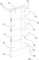
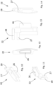
- the reference number 20 generally indicates a shutter as a whole comprising all the components thereof, the main of which are represented by a plurality of slats 21, hooked by ends thereof to a respective slat holder support 22, which is rotatably associated to a respective chain element 23, which chain element 23, together with further chain elements 23 consecutively connected to one another by the various slat holder supports 22, is inserted in a groove 24 formed on a vertical profile 25, positionable in the compartment of a window or a French window or another outward opening of a building.
- each slat 21 is made using an elongated and particularly shaped profiled element comprising a central through cavity made in such a way that the two ends of each slat allow accommodating respective slat holder elements 22 which perform the function of respective closing caps and of support for the lifting, lowering and orientation operations of the slats of the shutter itself, for a total of two mirror supports for each slat, which are fixed on the same ends in order to remain constrained thereto.
- each slat holder support 22 is configured according to the same profile of each slat and comprises a shaped projection 26 designed to be introduced into the central through cavity when the slat holder is applied by joint-fitting on the end of the respective slat, in such a way as to form a single body with the same.
- each slat holder 22 superiorly comprises two pins 27 and 28 that are parallel to one another and arranged on the opposite side to the slat holder with respect to the profiled projection 26.
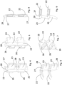
- each chain element 23, as represented in Figures 15 to 19 is made with a body also having a shape that resembles the one of the slat holder 22, and is provided, at the two opposite ends thereof, with two holes arranged parallel, indicated respectively with 29 and 30, of which the first is lower and the second is higher.
- each chain element 23 is destined to accommodate the upper pin 28 of the slat holder located on the lower slat, while the upper hole 30 accommodates the lower pin 27 of the slat holder located on the same level.
- Each slat holder remains constrained to a pair of consecutive chain elements 23, with the possibility of angular rotation on the parallel axes of the pins 27 and 28, by screws 31 which are inserted passing through the holes in the pins 27 and 28 of the slat holders 22, to penetrate into channels 32 formed longitudinally in the profiled element of each slat 21 and to stably fix the same slat 21 to the respective slat holder 22.
- the head of each screw 31 effectively prevents each slat holder from slipping off the respective chain elements 23 to which it is coupled, i.e. the corresponding one and the one immediately above.
- the lower part of the shutter comprises compensation elements represented by profiles 33, 34 arranged parallel with respect to the slats 21, which constitute the lower terminal part of the curtain, and by respective lateral closing elements 35, 36.
- the profile 33 is free to slide vertically inside the profile 34 with a travel that defines the space in which the user of the shutter can halt the unwinding of the curtain and obtain an intermediate condition of the shutter fully lowered, but with the slats closed.
- the chain elements 23 are exclusively connected by means of the pins 27 and 28 present on the slat holder 22 and, consequently, each slat holder connects two chain elements 23, i.e. one being its own chain and one being the chain located immediately above.
- slats 21 are fixed only on the respective slat holders 22 from which they take the motion, consequently there is no direct connection between the slats themselves, or by means of other profiles.
- the pin 28 passes from a position overlying the position of the lower pin 27 (closed slats) to a position in which the upper pin is flanked to the lower pin 27 (oriented slats).
- a too small width of the groove 24 could prevent all the travel of the pin 28 about the axis of the hole 30 causing an undesirable lower degree of orientation.
- the aforementioned compensation system constituted by the profiles 33 and 34 which represent the lower terminal part of the curtain, and the respective lateral closing elements 35 and 36, has the function of allowing the user to easily identify the intermediate condition of the shutter in which the curtain is fully lowered, but all the slats are closed, that is not oriented.
- the profile 33 results to be inserted in the profile 34 and has the possibility of sliding therein in a telescopic manner in a vertical direction.
- the travel of the profile 33 in the profile 34 defines the space in which the user of the shutter can halt the unwinding of the curtain and obtain the aforementioned intermediate condition.
- the further unwinding brings the profile 33 to rest on the bottom of the profile 34 with consequently unloading of the weight of the shutter on the threshold of the compartment in which it is placed with the effect that the force of gravity determined by the weight of the shutter is unloaded onto the pins 28 setting them in rotation about the axes of the holes 30 and of the pins 27 and by progressively causing all the slats to rotate.
Landscapes
- Engineering & Computer Science (AREA)
- Structural Engineering (AREA)
- Architecture (AREA)
- Civil Engineering (AREA)
- Operating, Guiding And Securing Of Roll- Type Closing Members (AREA)
- Specific Sealing Or Ventilating Devices For Doors And Windows (AREA)
- Blinds (AREA)
Claims (11)
- Rollladen (20), umfassend eine Vielzahl von Latten (21), die durch Enden davon an einen jeweiligen Lattenhalterträger (22) eingehakt sind, der drehbar mit einem jeweiligen Kettenelement (23) assoziiert ist, wobei das Kettenelement (23), zusammen mit weiteren Kettenelementen (23), die konsekutiv miteinander verbunden sind, in eine Rille (24) eingesetzt ist, die an einem vertikalen Profil (25) gebildet ist, das in dem Abteil eines Fensters oder einer Fenstertür oder einer anderen Öffnung eines Gebäudes nach außen positionierbar ist, wodurch der genannte Lattenhalterträger (22) einen mit einem Profil versehenen Vorsprung (26) zum Zusammenfügen mit der jeweiligen Latte (21) umfasst, wobei der Rollladen dadurch gekennzeichnet ist, dass der genannte Lattenhalterträger ferner darüber einen oberen Stift (28) und einen unteren Stift (27) umfasst, die parallel zueinander sind und auf der Seite gegenüber dem Lattenhalter in Bezug auf den mit dem Profil versehenen Vorsprung (26) angeordnet sind, und dadurch, dass jedes Kettenelement (23), an den zwei gegenüberliegenden Enden davon, mit parallel angeordneten Löchern (29, 30) versehen ist, von denen ein erstes tiefer und ein zweites höher liegt, und wobei das untere Loch (29) jedes Kettenelements (23) dazu bestimmt ist, den oberen Stift (28) des Lattenhalters aufzunehmen, der auf der unteren Latte angeordnet ist, während das obere Loch (30) den unteren Stift (27) des Lattenhalters (22) aufnimmt, der auf derselben Höhe angeordnet ist.
- Rollladen (20) nach Anspruch 1, wobei jeder Lattenhalter (22) Haltemittel (31) umfasst, welche in jeweilige Löcher eingesetzt werden, die in den oberen und unteren Stiften (27, 28) bereitgestellt sind, um dann in Kanäle (32) eingeführt zu werden, die in Längsrichtung in dem mit dem Profil versehen Element jeder Latte (21) gebildet sind, und welche das Halten der Latte (21), des Lattenhalters (22) und der Kettenanordnung (23) auf derselben Höhe und der Kette (23) entsprechend der benachbarten oberen Latte bestimmen, mit einer Möglichkeit einer Winkeldrehung zwischen dem Lattenhalter (22) und den Ketten (23).
- Rollladen (20) nach einem der vorhergehenden Ansprüche, wobei die genannten Haltemittel (31), welche in jeweilige Löcher eingesetzt werden, die in den oberen und unteren Stiften (27, 28) bereitgestellt sind, um dann in Kanäle (32) eingeführt zu werden, mit denen die Latten (21) versehen sind, aus Gewindeschneidschrauben bestehen.
- Rollladen (20) nach einem der vorhergehenden Ansprüche, wobei die genannten Kettenelemente (23) ausschließlich mit Hilfe der oberen und unteren Stifte (27, 28) verbunden sind, die an dem Lattenhalter (22) vorhanden sind, und jeder Lattenhalter (22) zwei Kettenelemente (23) verbindet, d.h. wobei eines seine eigene Kette ist und das benachbarte die unmittelbar darüber angeordnete Kette ist.
- Rollladen (20) nach einem der vorhergehenden Ansprüche, wobei die genannten Latten (21) an den jeweiligen Lattenhaltern (22) befestigt sind, von denen die Latten (21) eine Bewegung empfangen.
- Rollladen (20) nach einem der vorhergehenden Ansprüche, wobei es nicht nur keine direkte Verbindung zwischen den Latten (21) gibt, sondern es auch keine andere Verbindung mit Hilfe anderer extrudierter Profile gibt.
- Rollladen (20) nach einem der vorhergehenden Ansprüche, wobei die Winkeldrehung der Latten während des Herunterlassens des Rollladens durch Schwerkraft stattfindet, die durch das Gewicht des Rollladens bestimmt wird, das beim Entladen auf die oberen Stifte (28) die Stifte in Drehung um die Achse der Löcher (30) und der unteren Stifte (27) versetzt, wodurch progressiv bewirkt wird, dass sich alle Latten drehen, während sich der obere Stift (28) jedes Lattenhalters (22), der in dem Loch (29) der unmittelbar darüberliegenden Kette (23) angeordnet ist, um die Achse des Lochs (30) dreht, in dem der untere Stift (27) desselben Lattenhalters (22) aufgenommen ist, wodurch der gesamte Lattenhalter und somit die jeweilige Latte (21) in Drehung versetzt werden.
- Rollladen (20) nach einem der vorhergehenden Ansprüche, wobei der genannte obere Stift (28), aufgrund der Winkeldrehung der Latten, die während des Herunterlassens des Rollladens auftritt, von einer anfänglichen Position, die über der Position des unteren Stifts (27) liegt, in welcher die Latten geschlossen sind, in eine Position übergeht, in welcher der obere Stift (28) von dem unteren Stift (27) flankiert wird, wobei die Latten ausgerichtet werden.
- Rollladen (20) nach einem der vorhergehenden Ansprüche, wobei der untere Teil des Rollladens Kompensationselemente umfasst, welche von einem ersten Profil (33) und einem zweiten Profil (34) repräsentiert werden, die in Bezug auf die Latten (21) parallel angeordnet sind und an Enden davon durch Kappen (35, 36) verschlossen sind, wodurch die Kompensationselemente den untersten letzten Teil des Vorhangs darstellen.
- Rollladen (20) nach Anspruch 9, wobei die Bewegung des ersten Profils (33) in dem zweiten Profil (34) den Raum definiert, in dem der Benutzer des Rollladens das Abrollen des Vorhangs anhalten kann und einen Zwischenzustand des vollständig heruntergelassenen Rollladens, jedoch mit geschlossenen Latten erhalten kann.
- Rollladen (20) nach einem der vorhergehenden Ansprüche, wobei das Schließen der Latten stattfindet, wenn beim Aufrollen des Vorhangs um die Wickelrolle das Gewicht aufhört, sich auf den oberen Stift (28) abzuladen, der im Gegensatz dazu durch die Schwerkraft des unteren Teils des Vorhangs dazu gebracht wird, die anfängliche Position davon über dem unteren Stift (27) einzunehmen.
Applications Claiming Priority (2)
| Application Number | Priority Date | Filing Date | Title |
|---|---|---|---|
| IT102019000018392A IT201900018392A1 (it) | 2019-10-10 | 2019-10-10 | Tapparella avvolgibile a lamelle orientabili provvista di mezzi semplificati per la rotazione angolare |
| PCT/IB2020/059091 WO2021070003A1 (en) | 2019-10-10 | 2020-09-29 | Roller shutter with orientable slats provided with a simplified means for angular rotation |
Publications (2)
| Publication Number | Publication Date |
|---|---|
| EP4041978A1 EP4041978A1 (de) | 2022-08-17 |
| EP4041978B1 true EP4041978B1 (de) | 2023-05-10 |
Family
ID=69743668
Family Applications (1)
| Application Number | Title | Priority Date | Filing Date |
|---|---|---|---|
| EP20775159.5A Active EP4041978B1 (de) | 2019-10-10 | 2020-09-29 | Rollladen mit ausrichtbaren latten mit vereinfachter vorrichtung zur winkeldrehung |
Country Status (4)
| Country | Link |
|---|---|
| EP (1) | EP4041978B1 (de) |
| ES (1) | ES2948834T3 (de) |
| IT (1) | IT201900018392A1 (de) |
| WO (1) | WO2021070003A1 (de) |
Families Citing this family (1)
| Publication number | Priority date | Publication date | Assignee | Title |
|---|---|---|---|---|
| EP4726165A1 (de) | 2024-10-09 | 2026-04-15 | Nunzio Spontella | Mechanismus für einen aufrollbaren sonnenschutzladen und zugehöriger rollladen |
Citations (3)
| Publication number | Priority date | Publication date | Assignee | Title |
|---|---|---|---|---|
| EP2811103A1 (de) * | 2013-06-05 | 2014-12-10 | De Carlo, Nicola | Als Rollo und Jalousie funktionierender Rollladen |
| EP3221544B1 (de) * | 2014-11-21 | 2018-07-25 | Teknalsystem S.r.l. | Rollladen mit verstellbaren, vor ort auf standardführungen installierten lamellen |
| US20190271155A1 (en) * | 2018-03-05 | 2019-09-05 | Nathan Gilbertson | Integrated fenestration wall assembly |
Family Cites Families (6)
| Publication number | Priority date | Publication date | Assignee | Title |
|---|---|---|---|---|
| ES2043131T3 (es) | 1989-02-07 | 1993-12-16 | Guenther Erber | Persiana convertible en persiana de tablillas moviles. |
| ES2154114B1 (es) | 1997-11-07 | 2001-10-16 | Gradhermetic Ind | Estructura autoportante para una persiana de lamas arrollables. |
| ITMT20090001A1 (it) | 2009-01-19 | 2010-07-19 | Nicola Benedetto | Avvolgibile a stecche orientabili senza meccanismo di movimentazione, atto ad ottenere in modo contemporaneo sia la protezione che l'aerazione dei locali. |
| JP5962952B2 (ja) * | 2012-01-25 | 2016-08-03 | アイシン精機株式会社 | シャッタ装置 |
| EP2722475B1 (de) | 2012-10-19 | 2015-07-01 | Teknalsystem S.r.l. | Rollladen mit Kipplamellen |
| ITRM20150158A1 (it) | 2015-04-14 | 2016-10-14 | Kikau Srl | Persiana avvolgibile con lamelle orientabili |
-
2019
- 2019-10-10 IT IT102019000018392A patent/IT201900018392A1/it unknown
-
2020
- 2020-09-29 EP EP20775159.5A patent/EP4041978B1/de active Active
- 2020-09-29 ES ES20775159T patent/ES2948834T3/es active Active
- 2020-09-29 WO PCT/IB2020/059091 patent/WO2021070003A1/en not_active Ceased
Patent Citations (3)
| Publication number | Priority date | Publication date | Assignee | Title |
|---|---|---|---|---|
| EP2811103A1 (de) * | 2013-06-05 | 2014-12-10 | De Carlo, Nicola | Als Rollo und Jalousie funktionierender Rollladen |
| EP3221544B1 (de) * | 2014-11-21 | 2018-07-25 | Teknalsystem S.r.l. | Rollladen mit verstellbaren, vor ort auf standardführungen installierten lamellen |
| US20190271155A1 (en) * | 2018-03-05 | 2019-09-05 | Nathan Gilbertson | Integrated fenestration wall assembly |
Also Published As
| Publication number | Publication date |
|---|---|
| WO2021070003A1 (en) | 2021-04-15 |
| EP4041978A1 (de) | 2022-08-17 |
| IT201900018392A1 (it) | 2021-04-10 |
| ES2948834T3 (es) | 2023-09-20 |
Similar Documents
| Publication | Publication Date | Title |
|---|---|---|
| US5469658A (en) | Louvre shutter device with variable slats | |
| US9347261B2 (en) | Adjustment mechanisms for shades | |
| US9133661B2 (en) | Vertical blind assembly | |
| EP2398993B1 (de) | Jalousierbarer Rollladen | |
| US9260913B2 (en) | Vertical blind assembly | |
| EP3000958B1 (de) | Stoffrollo | |
| US20100263804A1 (en) | Window blinds that let in air but block out light | |
| US9976344B2 (en) | System for closing a venetian blind or the like housed in a double glazing or in a double glass, provided with means for preventing a movement of the blind during the transport or assembly of the system | |
| EP4041978B1 (de) | Rollladen mit ausrichtbaren latten mit vereinfachter vorrichtung zur winkeldrehung | |
| US20190211621A1 (en) | Window covering for an arched window | |
| US20150292260A1 (en) | Covering device | |
| EP3431698A1 (de) | Geweberollo | |
| WO2004059116A1 (en) | Motorised blinds and shutters | |
| EP3221544B1 (de) | Rollladen mit verstellbaren, vor ort auf standardführungen installierten lamellen | |
| KR20170000381U (ko) | 합성수지와 금속재질을 이용한 복합창호 | |
| EP3670820B1 (de) | Geweberollo | |
| AU2011343291A1 (en) | Mechanism for rotating the slats of a roller shutter | |
| EP3296503B1 (de) | Geweberollo mit einer vorrichtung zur einstellung der spannung | |
| IT202100017459A1 (it) | Porta scorrevole | |
| EP4097326B1 (de) | Rolladen mit verstellbaren lamellen | |
| GR1004013B (el) | Συστημα προφιλ αλουμινιου δομησεως ανοιγομενων πατζουριων θυρων/παραθυρων και εν γενει πετασματων ενος η πολλαπλων περιστρεψιμα συνδεδεμενων φυλλων. | |
| EP3670817B1 (de) | Rollo mit haltevorrichtung für die wickelwelle | |
| EP3249148B1 (de) | Stoffrollo | |
| KR200216468Y1 (ko) | 블라인드 이중창 | |
| JP3189111U (ja) | ブラインド式雨戸 |
Legal Events
| Date | Code | Title | Description |
|---|---|---|---|
| STAA | Information on the status of an ep patent application or granted ep patent |
Free format text: STATUS: UNKNOWN |
|
| STAA | Information on the status of an ep patent application or granted ep patent |
Free format text: STATUS: THE INTERNATIONAL PUBLICATION HAS BEEN MADE |
|
| PUAI | Public reference made under article 153(3) epc to a published international application that has entered the european phase |
Free format text: ORIGINAL CODE: 0009012 |
|
| STAA | Information on the status of an ep patent application or granted ep patent |
Free format text: STATUS: REQUEST FOR EXAMINATION WAS MADE |
|
| 17P | Request for examination filed |
Effective date: 20220413 |
|
| AK | Designated contracting states |
Kind code of ref document: A1 Designated state(s): AL AT BE BG CH CY CZ DE DK EE ES FI FR GB GR HR HU IE IS IT LI LT LU LV MC MK MT NL NO PL PT RO RS SE SI SK SM TR |
|
| GRAP | Despatch of communication of intention to grant a patent |
Free format text: ORIGINAL CODE: EPIDOSNIGR1 |
|
| STAA | Information on the status of an ep patent application or granted ep patent |
Free format text: STATUS: GRANT OF PATENT IS INTENDED |
|
| DAV | Request for validation of the european patent (deleted) | ||
| DAX | Request for extension of the european patent (deleted) | ||
| INTG | Intention to grant announced |
Effective date: 20230103 |
|
| GRAS | Grant fee paid |
Free format text: ORIGINAL CODE: EPIDOSNIGR3 |
|
| GRAA | (expected) grant |
Free format text: ORIGINAL CODE: 0009210 |
|
| STAA | Information on the status of an ep patent application or granted ep patent |
Free format text: STATUS: THE PATENT HAS BEEN GRANTED |
|
| AK | Designated contracting states |
Kind code of ref document: B1 Designated state(s): AL AT BE BG CH CY CZ DE DK EE ES FI FR GB GR HR HU IE IS IT LI LT LU LV MC MK MT NL NO PL PT RO RS SE SI SK SM TR |
|
| REG | Reference to a national code |
Ref country code: GB Ref legal event code: FG4D |
|
| REG | Reference to a national code |
Ref country code: AT Ref legal event code: REF Ref document number: 1566836 Country of ref document: AT Kind code of ref document: T Effective date: 20230515 Ref country code: CH Ref legal event code: EP |
|
| REG | Reference to a national code |
Ref country code: DE Ref legal event code: R096 Ref document number: 602020010816 Country of ref document: DE |
|
| REG | Reference to a national code |
Ref country code: IE Ref legal event code: FG4D |
|
| P01 | Opt-out of the competence of the unified patent court (upc) registered |
Effective date: 20230524 |
|
| REG | Reference to a national code |
Ref country code: LT Ref legal event code: MG9D |
|
| REG | Reference to a national code |
Ref country code: NL Ref legal event code: MP Effective date: 20230510 |
|
| REG | Reference to a national code |
Ref country code: ES Ref legal event code: FG2A Ref document number: 2948834 Country of ref document: ES Kind code of ref document: T3 Effective date: 20230920 |
|
| REG | Reference to a national code |
Ref country code: AT Ref legal event code: MK05 Ref document number: 1566836 Country of ref document: AT Kind code of ref document: T Effective date: 20230510 |
|
| PG25 | Lapsed in a contracting state [announced via postgrant information from national office to epo] |
Ref country code: SE Free format text: LAPSE BECAUSE OF FAILURE TO SUBMIT A TRANSLATION OF THE DESCRIPTION OR TO PAY THE FEE WITHIN THE PRESCRIBED TIME-LIMIT Effective date: 20230510 Ref country code: PT Free format text: LAPSE BECAUSE OF FAILURE TO SUBMIT A TRANSLATION OF THE DESCRIPTION OR TO PAY THE FEE WITHIN THE PRESCRIBED TIME-LIMIT Effective date: 20230911 Ref country code: NO Free format text: LAPSE BECAUSE OF FAILURE TO SUBMIT A TRANSLATION OF THE DESCRIPTION OR TO PAY THE FEE WITHIN THE PRESCRIBED TIME-LIMIT Effective date: 20230810 Ref country code: NL Free format text: LAPSE BECAUSE OF FAILURE TO SUBMIT A TRANSLATION OF THE DESCRIPTION OR TO PAY THE FEE WITHIN THE PRESCRIBED TIME-LIMIT Effective date: 20230510 Ref country code: AT Free format text: LAPSE BECAUSE OF FAILURE TO SUBMIT A TRANSLATION OF THE DESCRIPTION OR TO PAY THE FEE WITHIN THE PRESCRIBED TIME-LIMIT Effective date: 20230510 |
|
| PG25 | Lapsed in a contracting state [announced via postgrant information from national office to epo] |
Ref country code: RS Free format text: LAPSE BECAUSE OF FAILURE TO SUBMIT A TRANSLATION OF THE DESCRIPTION OR TO PAY THE FEE WITHIN THE PRESCRIBED TIME-LIMIT Effective date: 20230510 Ref country code: PL Free format text: LAPSE BECAUSE OF FAILURE TO SUBMIT A TRANSLATION OF THE DESCRIPTION OR TO PAY THE FEE WITHIN THE PRESCRIBED TIME-LIMIT Effective date: 20230510 Ref country code: LV Free format text: LAPSE BECAUSE OF FAILURE TO SUBMIT A TRANSLATION OF THE DESCRIPTION OR TO PAY THE FEE WITHIN THE PRESCRIBED TIME-LIMIT Effective date: 20230510 Ref country code: LT Free format text: LAPSE BECAUSE OF FAILURE TO SUBMIT A TRANSLATION OF THE DESCRIPTION OR TO PAY THE FEE WITHIN THE PRESCRIBED TIME-LIMIT Effective date: 20230510 Ref country code: IS Free format text: LAPSE BECAUSE OF FAILURE TO SUBMIT A TRANSLATION OF THE DESCRIPTION OR TO PAY THE FEE WITHIN THE PRESCRIBED TIME-LIMIT Effective date: 20230910 Ref country code: HR Free format text: LAPSE BECAUSE OF FAILURE TO SUBMIT A TRANSLATION OF THE DESCRIPTION OR TO PAY THE FEE WITHIN THE PRESCRIBED TIME-LIMIT Effective date: 20230510 Ref country code: GR Free format text: LAPSE BECAUSE OF FAILURE TO SUBMIT A TRANSLATION OF THE DESCRIPTION OR TO PAY THE FEE WITHIN THE PRESCRIBED TIME-LIMIT Effective date: 20230811 |
|
| PG25 | Lapsed in a contracting state [announced via postgrant information from national office to epo] |
Ref country code: FI Free format text: LAPSE BECAUSE OF FAILURE TO SUBMIT A TRANSLATION OF THE DESCRIPTION OR TO PAY THE FEE WITHIN THE PRESCRIBED TIME-LIMIT Effective date: 20230510 |
|
| PG25 | Lapsed in a contracting state [announced via postgrant information from national office to epo] |
Ref country code: SK Free format text: LAPSE BECAUSE OF FAILURE TO SUBMIT A TRANSLATION OF THE DESCRIPTION OR TO PAY THE FEE WITHIN THE PRESCRIBED TIME-LIMIT Effective date: 20230510 |
|
| PG25 | Lapsed in a contracting state [announced via postgrant information from national office to epo] |
Ref country code: SM Free format text: LAPSE BECAUSE OF FAILURE TO SUBMIT A TRANSLATION OF THE DESCRIPTION OR TO PAY THE FEE WITHIN THE PRESCRIBED TIME-LIMIT Effective date: 20230510 Ref country code: SK Free format text: LAPSE BECAUSE OF FAILURE TO SUBMIT A TRANSLATION OF THE DESCRIPTION OR TO PAY THE FEE WITHIN THE PRESCRIBED TIME-LIMIT Effective date: 20230510 Ref country code: RO Free format text: LAPSE BECAUSE OF FAILURE TO SUBMIT A TRANSLATION OF THE DESCRIPTION OR TO PAY THE FEE WITHIN THE PRESCRIBED TIME-LIMIT Effective date: 20230510 Ref country code: EE Free format text: LAPSE BECAUSE OF FAILURE TO SUBMIT A TRANSLATION OF THE DESCRIPTION OR TO PAY THE FEE WITHIN THE PRESCRIBED TIME-LIMIT Effective date: 20230510 Ref country code: DK Free format text: LAPSE BECAUSE OF FAILURE TO SUBMIT A TRANSLATION OF THE DESCRIPTION OR TO PAY THE FEE WITHIN THE PRESCRIBED TIME-LIMIT Effective date: 20230510 Ref country code: CZ Free format text: LAPSE BECAUSE OF FAILURE TO SUBMIT A TRANSLATION OF THE DESCRIPTION OR TO PAY THE FEE WITHIN THE PRESCRIBED TIME-LIMIT Effective date: 20230510 |
|
| REG | Reference to a national code |
Ref country code: DE Ref legal event code: R097 Ref document number: 602020010816 Country of ref document: DE |
|
| PLBE | No opposition filed within time limit |
Free format text: ORIGINAL CODE: 0009261 |
|
| STAA | Information on the status of an ep patent application or granted ep patent |
Free format text: STATUS: NO OPPOSITION FILED WITHIN TIME LIMIT |
|
| 26N | No opposition filed |
Effective date: 20240213 |
|
| REG | Reference to a national code |
Ref country code: CH Ref legal event code: PL |
|
| PG25 | Lapsed in a contracting state [announced via postgrant information from national office to epo] |
Ref country code: SI Free format text: LAPSE BECAUSE OF FAILURE TO SUBMIT A TRANSLATION OF THE DESCRIPTION OR TO PAY THE FEE WITHIN THE PRESCRIBED TIME-LIMIT Effective date: 20230510 |
|
| PG25 | Lapsed in a contracting state [announced via postgrant information from national office to epo] |
Ref country code: LU Free format text: LAPSE BECAUSE OF NON-PAYMENT OF DUE FEES Effective date: 20230929 |
|
| REG | Reference to a national code |
Ref country code: BE Ref legal event code: MM Effective date: 20230930 |
|
| PG25 | Lapsed in a contracting state [announced via postgrant information from national office to epo] |
Ref country code: SI Free format text: LAPSE BECAUSE OF FAILURE TO SUBMIT A TRANSLATION OF THE DESCRIPTION OR TO PAY THE FEE WITHIN THE PRESCRIBED TIME-LIMIT Effective date: 20230510 Ref country code: LU Free format text: LAPSE BECAUSE OF NON-PAYMENT OF DUE FEES Effective date: 20230929 Ref country code: MC Free format text: LAPSE BECAUSE OF FAILURE TO SUBMIT A TRANSLATION OF THE DESCRIPTION OR TO PAY THE FEE WITHIN THE PRESCRIBED TIME-LIMIT Effective date: 20230510 |
|
| REG | Reference to a national code |
Ref country code: IE Ref legal event code: MM4A |
|
| PG25 | Lapsed in a contracting state [announced via postgrant information from national office to epo] |
Ref country code: IE Free format text: LAPSE BECAUSE OF NON-PAYMENT OF DUE FEES Effective date: 20230929 |
|
| PG25 | Lapsed in a contracting state [announced via postgrant information from national office to epo] |
Ref country code: CH Free format text: LAPSE BECAUSE OF NON-PAYMENT OF DUE FEES Effective date: 20230930 |
|
| PG25 | Lapsed in a contracting state [announced via postgrant information from national office to epo] |
Ref country code: IE Free format text: LAPSE BECAUSE OF NON-PAYMENT OF DUE FEES Effective date: 20230929 Ref country code: CH Free format text: LAPSE BECAUSE OF NON-PAYMENT OF DUE FEES Effective date: 20230930 |
|
| PG25 | Lapsed in a contracting state [announced via postgrant information from national office to epo] |
Ref country code: BE Free format text: LAPSE BECAUSE OF NON-PAYMENT OF DUE FEES Effective date: 20230930 |
|
| PG25 | Lapsed in a contracting state [announced via postgrant information from national office to epo] |
Ref country code: BG Free format text: LAPSE BECAUSE OF FAILURE TO SUBMIT A TRANSLATION OF THE DESCRIPTION OR TO PAY THE FEE WITHIN THE PRESCRIBED TIME-LIMIT Effective date: 20230510 |
|
| PG25 | Lapsed in a contracting state [announced via postgrant information from national office to epo] |
Ref country code: BG Free format text: LAPSE BECAUSE OF FAILURE TO SUBMIT A TRANSLATION OF THE DESCRIPTION OR TO PAY THE FEE WITHIN THE PRESCRIBED TIME-LIMIT Effective date: 20230510 |
|
| GBPC | Gb: european patent ceased through non-payment of renewal fee |
Effective date: 20240929 |
|
| PG25 | Lapsed in a contracting state [announced via postgrant information from national office to epo] |
Ref country code: GB Free format text: LAPSE BECAUSE OF NON-PAYMENT OF DUE FEES Effective date: 20240929 |
|
| PG25 | Lapsed in a contracting state [announced via postgrant information from national office to epo] |
Ref country code: CY Free format text: LAPSE BECAUSE OF FAILURE TO SUBMIT A TRANSLATION OF THE DESCRIPTION OR TO PAY THE FEE WITHIN THE PRESCRIBED TIME-LIMIT; INVALID AB INITIO Effective date: 20200929 |
|
| PG25 | Lapsed in a contracting state [announced via postgrant information from national office to epo] |
Ref country code: HU Free format text: LAPSE BECAUSE OF FAILURE TO SUBMIT A TRANSLATION OF THE DESCRIPTION OR TO PAY THE FEE WITHIN THE PRESCRIBED TIME-LIMIT; INVALID AB INITIO Effective date: 20200929 |
|
| PGFP | Annual fee paid to national office [announced via postgrant information from national office to epo] |
Ref country code: DE Payment date: 20250926 Year of fee payment: 6 |
|
| PGFP | Annual fee paid to national office [announced via postgrant information from national office to epo] |
Ref country code: IT Payment date: 20250923 Year of fee payment: 6 |
|
| PGFP | Annual fee paid to national office [announced via postgrant information from national office to epo] |
Ref country code: FR Payment date: 20250925 Year of fee payment: 6 |
|
| PG25 | Lapsed in a contracting state [announced via postgrant information from national office to epo] |
Ref country code: TR Free format text: LAPSE BECAUSE OF FAILURE TO SUBMIT A TRANSLATION OF THE DESCRIPTION OR TO PAY THE FEE WITHIN THE PRESCRIBED TIME-LIMIT Effective date: 20230510 |
|
| PGFP | Annual fee paid to national office [announced via postgrant information from national office to epo] |
Ref country code: ES Payment date: 20251015 Year of fee payment: 6 |