EP4041994B1 - Machine à flux pour l'alimentation en air d'un système de piles à combustible, procédé de fonctionnement d'une telle machine à flux - Google Patents
Machine à flux pour l'alimentation en air d'un système de piles à combustible, procédé de fonctionnement d'une telle machine à flux Download PDFInfo
- Publication number
- EP4041994B1 EP4041994B1 EP20765235.5A EP20765235A EP4041994B1 EP 4041994 B1 EP4041994 B1 EP 4041994B1 EP 20765235 A EP20765235 A EP 20765235A EP 4041994 B1 EP4041994 B1 EP 4041994B1
- Authority
- EP
- European Patent Office
- Prior art keywords
- air
- turbomachine
- shaft
- air channel
- compressor
- Prior art date
- Legal status (The legal status is an assumption and is not a legal conclusion. Google has not performed a legal analysis and makes no representation as to the accuracy of the status listed.)
- Active
Links
Images

Classifications
-
- H—ELECTRICITY
- H02—GENERATION; CONVERSION OR DISTRIBUTION OF ELECTRIC POWER
- H02K—DYNAMO-ELECTRIC MACHINES
- H02K9/00—Arrangements for cooling or ventilating
- H02K9/02—Arrangements for cooling or ventilating by ambient air flowing through the machine
-
- F—MECHANICAL ENGINEERING; LIGHTING; HEATING; WEAPONS; BLASTING
- F01—MACHINES OR ENGINES IN GENERAL; ENGINE PLANTS IN GENERAL; STEAM ENGINES
- F01D—NON-POSITIVE DISPLACEMENT MACHINES OR ENGINES, e.g. STEAM TURBINES
- F01D25/00—Component parts, details, or accessories, not provided for in, or of interest apart from, other groups
- F01D25/16—Arrangement of bearings; Supporting or mounting bearings in casings
-
- F—MECHANICAL ENGINEERING; LIGHTING; HEATING; WEAPONS; BLASTING
- F04—POSITIVE - DISPLACEMENT MACHINES FOR LIQUIDS; PUMPS FOR LIQUIDS OR ELASTIC FLUIDS
- F04D—NON-POSITIVE-DISPLACEMENT PUMPS
- F04D29/00—Details, component parts, or accessories
- F04D29/26—Rotors specially for elastic fluids
- F04D29/28—Rotors specially for elastic fluids for centrifugal or helico-centrifugal pumps for radial-flow or helico-centrifugal pumps
- F04D29/284—Rotors specially for elastic fluids for centrifugal or helico-centrifugal pumps for radial-flow or helico-centrifugal pumps for compressors
-
- F—MECHANICAL ENGINEERING; LIGHTING; HEATING; WEAPONS; BLASTING
- F01—MACHINES OR ENGINES IN GENERAL; ENGINE PLANTS IN GENERAL; STEAM ENGINES
- F01D—NON-POSITIVE DISPLACEMENT MACHINES OR ENGINES, e.g. STEAM TURBINES
- F01D25/00—Component parts, details, or accessories, not provided for in, or of interest apart from, other groups
- F01D25/16—Arrangement of bearings; Supporting or mounting bearings in casings
- F01D25/166—Sliding contact bearing
- F01D25/168—Sliding contact bearing for axial load mainly
-
- F—MECHANICAL ENGINEERING; LIGHTING; HEATING; WEAPONS; BLASTING
- F02—COMBUSTION ENGINES; HOT-GAS OR COMBUSTION-PRODUCT ENGINE PLANTS
- F02C—GAS-TURBINE PLANTS; AIR INTAKES FOR JET-PROPULSION PLANTS; CONTROLLING FUEL SUPPLY IN AIR-BREATHING JET-PROPULSION PLANTS
- F02C6/00—Plural gas-turbine plants; Combinations of gas-turbine plants with other apparatus; Adaptations of gas-turbine plants for special use
- F02C6/04—Gas-turbine plants providing heated or pressurised working fluid for other apparatus, e.g. without mechanical power output
- F02C6/10—Gas-turbine plants providing heated or pressurised working fluid for other apparatus, e.g. without mechanical power output supplying working fluid to a user, e.g. a chemical process, which returns working fluid to a turbine of the plant
- F02C6/12—Turbochargers, i.e. plants for augmenting mechanical power output of internal-combustion piston engines by increase of charge pressure
-
- F—MECHANICAL ENGINEERING; LIGHTING; HEATING; WEAPONS; BLASTING
- F02—COMBUSTION ENGINES; HOT-GAS OR COMBUSTION-PRODUCT ENGINE PLANTS
- F02C—GAS-TURBINE PLANTS; AIR INTAKES FOR JET-PROPULSION PLANTS; CONTROLLING FUEL SUPPLY IN AIR-BREATHING JET-PROPULSION PLANTS
- F02C6/00—Plural gas-turbine plants; Combinations of gas-turbine plants with other apparatus; Adaptations of gas-turbine plants for special use
- F02C6/18—Plural gas-turbine plants; Combinations of gas-turbine plants with other apparatus; Adaptations of gas-turbine plants for special use using the waste heat of gas-turbine plants outside the plants themselves, e.g. gas-turbine power heat plants
-
- F—MECHANICAL ENGINEERING; LIGHTING; HEATING; WEAPONS; BLASTING
- F04—POSITIVE - DISPLACEMENT MACHINES FOR LIQUIDS; PUMPS FOR LIQUIDS OR ELASTIC FLUIDS
- F04D—NON-POSITIVE-DISPLACEMENT PUMPS
- F04D17/00—Radial-flow pumps, e.g. centrifugal pumps; Helico-centrifugal pumps
- F04D17/08—Centrifugal pumps
- F04D17/10—Centrifugal pumps for compressing or evacuating
-
- F—MECHANICAL ENGINEERING; LIGHTING; HEATING; WEAPONS; BLASTING
- F04—POSITIVE - DISPLACEMENT MACHINES FOR LIQUIDS; PUMPS FOR LIQUIDS OR ELASTIC FLUIDS
- F04D—NON-POSITIVE-DISPLACEMENT PUMPS
- F04D25/00—Pumping installations or systems
- F04D25/02—Units comprising pumps and their driving means
- F04D25/06—Units comprising pumps and their driving means the pump being electrically driven
- F04D25/0606—Units comprising pumps and their driving means the pump being electrically driven the electric motor being specially adapted for integration in the pump
-
- F—MECHANICAL ENGINEERING; LIGHTING; HEATING; WEAPONS; BLASTING
- F04—POSITIVE - DISPLACEMENT MACHINES FOR LIQUIDS; PUMPS FOR LIQUIDS OR ELASTIC FLUIDS
- F04D—NON-POSITIVE-DISPLACEMENT PUMPS
- F04D25/00—Pumping installations or systems
- F04D25/02—Units comprising pumps and their driving means
- F04D25/08—Units comprising pumps and their driving means the working fluid being air, e.g. for ventilation
- F04D25/082—Units comprising pumps and their driving means the working fluid being air, e.g. for ventilation the unit having provision for cooling the motor
-
- F—MECHANICAL ENGINEERING; LIGHTING; HEATING; WEAPONS; BLASTING
- F04—POSITIVE - DISPLACEMENT MACHINES FOR LIQUIDS; PUMPS FOR LIQUIDS OR ELASTIC FLUIDS
- F04D—NON-POSITIVE-DISPLACEMENT PUMPS
- F04D29/00—Details, component parts, or accessories
- F04D29/05—Shafts or bearings, or assemblies thereof, specially adapted for elastic fluid pumps
- F04D29/051—Axial thrust balancing
- F04D29/0513—Axial thrust balancing hydrostatic; hydrodynamic thrust bearings
-
- F—MECHANICAL ENGINEERING; LIGHTING; HEATING; WEAPONS; BLASTING
- F04—POSITIVE - DISPLACEMENT MACHINES FOR LIQUIDS; PUMPS FOR LIQUIDS OR ELASTIC FLUIDS
- F04D—NON-POSITIVE-DISPLACEMENT PUMPS
- F04D29/00—Details, component parts, or accessories
- F04D29/05—Shafts or bearings, or assemblies thereof, specially adapted for elastic fluid pumps
- F04D29/056—Bearings
- F04D29/057—Bearings hydrostatic; hydrodynamic
-
- H—ELECTRICITY
- H02—GENERATION; CONVERSION OR DISTRIBUTION OF ELECTRIC POWER
- H02K—DYNAMO-ELECTRIC MACHINES
- H02K7/00—Arrangements for handling mechanical energy structurally associated with dynamo-electric machines, e.g. structural association with mechanical driving motors or auxiliary dynamo-electric machines
- H02K7/10—Structural association with clutches, brakes, gears, pulleys or mechanical starters
-
- F—MECHANICAL ENGINEERING; LIGHTING; HEATING; WEAPONS; BLASTING
- F02—COMBUSTION ENGINES; HOT-GAS OR COMBUSTION-PRODUCT ENGINE PLANTS
- F02B—INTERNAL-COMBUSTION PISTON ENGINES; COMBUSTION ENGINES IN GENERAL
- F02B39/00—Component parts, details, or accessories relating to, driven charging or scavenging pumps, not provided for in groups F02B33/00 - F02B37/00
- F02B39/005—Cooling of pump drives
-
- F—MECHANICAL ENGINEERING; LIGHTING; HEATING; WEAPONS; BLASTING
- F04—POSITIVE - DISPLACEMENT MACHINES FOR LIQUIDS; PUMPS FOR LIQUIDS OR ELASTIC FLUIDS
- F04D—NON-POSITIVE-DISPLACEMENT PUMPS
- F04D29/00—Details, component parts, or accessories
- F04D29/26—Rotors specially for elastic fluids
- F04D29/266—Rotors specially for elastic fluids mounting compressor rotors on shafts
-
- F—MECHANICAL ENGINEERING; LIGHTING; HEATING; WEAPONS; BLASTING
- F04—POSITIVE - DISPLACEMENT MACHINES FOR LIQUIDS; PUMPS FOR LIQUIDS OR ELASTIC FLUIDS
- F04D—NON-POSITIVE-DISPLACEMENT PUMPS
- F04D29/00—Details, component parts, or accessories
- F04D29/58—Cooling; Heating; Diminishing heat transfer
- F04D29/5806—Cooling the drive system
-
- F—MECHANICAL ENGINEERING; LIGHTING; HEATING; WEAPONS; BLASTING
- F04—POSITIVE - DISPLACEMENT MACHINES FOR LIQUIDS; PUMPS FOR LIQUIDS OR ELASTIC FLUIDS
- F04D—NON-POSITIVE-DISPLACEMENT PUMPS
- F04D29/00—Details, component parts, or accessories
- F04D29/58—Cooling; Heating; Diminishing heat transfer
- F04D29/582—Cooling; Heating; Diminishing heat transfer specially adapted for elastic fluid pumps
- F04D29/584—Cooling; Heating; Diminishing heat transfer specially adapted for elastic fluid pumps cooling or heating the machine
-
- F—MECHANICAL ENGINEERING; LIGHTING; HEATING; WEAPONS; BLASTING
- F04—POSITIVE - DISPLACEMENT MACHINES FOR LIQUIDS; PUMPS FOR LIQUIDS OR ELASTIC FLUIDS
- F04D—NON-POSITIVE-DISPLACEMENT PUMPS
- F04D29/00—Details, component parts, or accessories
- F04D29/58—Cooling; Heating; Diminishing heat transfer
- F04D29/582—Cooling; Heating; Diminishing heat transfer specially adapted for elastic fluid pumps
- F04D29/5846—Cooling; Heating; Diminishing heat transfer specially adapted for elastic fluid pumps cooling by injection
-
- F—MECHANICAL ENGINEERING; LIGHTING; HEATING; WEAPONS; BLASTING
- F05—INDEXING SCHEMES RELATING TO ENGINES OR PUMPS IN VARIOUS SUBCLASSES OF CLASSES F01-F04
- F05D—INDEXING SCHEME FOR ASPECTS RELATING TO NON-POSITIVE-DISPLACEMENT MACHINES OR ENGINES, GAS-TURBINES OR JET-PROPULSION PLANTS
- F05D2220/00—Application
- F05D2220/40—Application in turbochargers
-
- H—ELECTRICITY
- H01—ELECTRIC ELEMENTS
- H01M—PROCESSES OR MEANS, e.g. BATTERIES, FOR THE DIRECT CONVERSION OF CHEMICAL ENERGY INTO ELECTRICAL ENERGY
- H01M8/00—Fuel cells; Manufacture thereof
- H01M8/04—Auxiliary arrangements, e.g. for control of pressure or for circulation of fluids
- H01M8/04082—Arrangements for control of reactant parameters, e.g. pressure or concentration
- H01M8/04089—Arrangements for control of reactant parameters, e.g. pressure or concentration of gaseous reactants
- H01M8/04111—Arrangements for control of reactant parameters, e.g. pressure or concentration of gaseous reactants using a compressor turbine assembly
-
- Y—GENERAL TAGGING OF NEW TECHNOLOGICAL DEVELOPMENTS; GENERAL TAGGING OF CROSS-SECTIONAL TECHNOLOGIES SPANNING OVER SEVERAL SECTIONS OF THE IPC; TECHNICAL SUBJECTS COVERED BY FORMER USPC CROSS-REFERENCE ART COLLECTIONS [XRACs] AND DIGESTS
- Y02—TECHNOLOGIES OR APPLICATIONS FOR MITIGATION OR ADAPTATION AGAINST CLIMATE CHANGE
- Y02E—REDUCTION OF GREENHOUSE GAS [GHG] EMISSIONS, RELATED TO ENERGY GENERATION, TRANSMISSION OR DISTRIBUTION
- Y02E60/00—Enabling technologies; Technologies with a potential or indirect contribution to GHG emissions mitigation
- Y02E60/30—Hydrogen technology
- Y02E60/50—Fuel cells
Definitions
- the invention relates to a turbomachine with the features of the preamble of claim 1.
- the turbomachine can be used in particular for supplying air to fuel cell systems.
- the invention relates to a method for operating such a turbomachine.
- Fuel cell systems require oxygen, which reacts with hydrogen in a fuel cell of the system to form water or water vapor. In this way, electrical power is generated through electrochemical conversion, which can be used as drive energy, for example to drive a vehicle.
- the oxygen source is usually ambient air, which is fed to the fuel cell by means of an air compression system, since the process requires a certain air mass flow and a certain pressure level.
- the air compression system comprises a high-speed turbo machine with at least one compressor wheel arranged on a shaft, which is driven by an electric motor. To recover energy, a turbine wheel can be arranged on the shaft, to which fuel cell exhaust air is fed.
- the turbo machine is an exhaust gas turbocharger with an additional electric motor.
- the maximum speed of the additional electric motor is limited for control and strength reasons, for example to a maximum of between 100,000 and 125,000 rpm.
- Exhaust gas turbochargers without an additional electric motor reach speeds between 180,000 and 250,000 rpm.
- the achievable compressor outlet pressure in a turbomachine is proportional to the square of the circumferential speed at the outer diameter of the compressor wheel. This means that it is determined by the speed and the The outer diameter of the compressor wheel is determined. Due to the pressures required for the fuel cell system and the speed limitation mentioned above, compressor wheels with comparatively large outer diameters are required. These generate large axial forces in the direction of the compressor inlet, since the pressure at the compressor outlet is applied to the back of the compressor wheel during operation. The high axial forces in turn require correspondingly large axial bearings. However, the larger the axial bearings, the greater the power loss, with the axial bearings having a significantly larger share (2/3 share) of the total bearing losses than the radial bearings (1/3 share).
- Turbomachines that supply air to fuel cell systems usually have foil air bearings to keep the system oil-free.
- foil air bearings generate air friction losses and are therefore cooled using additional air.
- around 5 to 10% of the compressed air is usually diverted for cooling. This diverted amount of air is then no longer available for the process in the fuel cell and thus reduces the efficiency of the turbomachine.
- the diverted air In order for the diverted air to be able to provide any cooling power at all, it is first cooled itself.
- the cooling air is usually diverted behind a charge air cooler of the fuel cell system. The additional cooling requirement must be taken into account when designing the charge air cooler.
- an additional line must be provided through which the cooling air can be supplied to the turbomachine.
- Turbomachines for energy converters, in particular for fuel cells, with a compressor for compressing air to be supplied to the energy converter are described in the documents EN 10 2015 007 379 A1 and EN 10 2014 018 096 A1 described.
- the present invention is based on the object of improving the efficiency of a turbomachine for supplying air to a fuel cell system.
- the turbomachine proposed for supplying air to a fuel cell system comprises at least one compressor wheel connected to a shaft in a rotationally fixed manner and an electric motor for driving the shaft, the compressor wheel being connected to a preferably hollow-cylindrical shaft section of the shaft in a rotationally fixed manner via a hub section.
- at least one air channel is formed in the hub section, via which a compressor inlet is connected to an annular space on the side of the compressor wheel facing away from the compressor inlet, so that essentially the same air pressure is present on both sides of the compressor wheel.
- the annular space on the side of the compressor wheel facing away from the compressor inlet is connected to at least one bearing of the shaft via at least one further air duct.
- the air supplied via the at least one further air duct can be used to cool the at least one bearing.
- the at least one further air duct for connecting at least one shaft bearing to the annular space and thus to the compressor inlet side is also connected via an annular gap between the shaft and a winding of the electric motor that surrounds the shaft. This means that the air supplied via at least one additional air duct can be used to cool the electric motor.
- the hub section preferably has at least one axially running air duct.
- the air duct can be designed as an axial bore, for example. If only one axially running air duct is provided, this is preferably arranged centrally or coaxially to the longitudinal axis of the shaft.
- the at least one axially running air duct is preferably in direct connection with the compressor inlet side, so that a partial flow of the air supplied to the compressor wheel is branched off via the at least one axially running air duct and guided to the rear of the compressor wheel.
- the hub section preferably has at least one essentially radially extending air duct.
- the at least one essentially radially extending air duct can be used to establish a connection between the at least one axially extending air duct and the annular space on the rear side of the compressor wheel.
- the essentially radially extending air duct can be formed, for example, by a radial bore in the hub section.
- the hub section preferably has several essentially radially extending air ducts that are arranged at the same angular distance from one another. The air guided behind the compressor wheel is thus evenly distributed in the annular space.
- the hub section is inserted, in particular pressed, at least in sections into the hollow cylindrical shaft section.
- the interlocking of the sections increases the rigidity and thus the stability of the composite.
- the hollow cylindrical shaft section has at least one substantially radially extending air channel which overlaps with the at least one radially extending air channel of the hub section.
- the at least one essentially radially extending air channel of the hub section can therefore be arranged in an area that is inserted, in particular pressed, into the hollow cylindrical shaft section. In this way, a turbomachine that is compact in the axial direction is created.
- the at least one bearing is designed as a foil air bearing so that the oil-free nature of the system is ensured.
- the at least one further air duct is guided through an internally ventilated axial bearing disk that is connected to the shaft in a rotationally fixed manner to support a turbine wheel.
- a pressure stroke can also be achieved.
- the air pressure of the air supplied via the at least one further air duct can be raised to the level in front of the turbine wheel.
- Air is sucked in from the environment via the compressor inlet.
- the sucked in air is therefore at ambient temperature and therefore has a very low temperature level. This means that the rotor and bearing cooling function can usually be optimally fulfilled.
- the air ducts can also be supplied with cooled ambient air, i.e. air that has itself been cooled beforehand. According to a preferred embodiment of the invention, all air ducts that connect the compressor inlet to the rear annular space and possibly at least one shaft bearing can therefore be supplied with cooled or uncooled ambient air.
- the air pressure of the cooled or uncooled ambient air can be raised to the level in front of the turbine wheel via the internally ventilated axial bearing disk, so that at least part of the energy required for the cooling air supply is recovered with the help of the turbine.
- a modification consists in dispensing with the pressure stroke through the internally ventilated axial bearing disk and returning the ambient air behind the turbine outlet into the system.
- a method for operating a turbomachine according to the invention is also proposed.
- the air ducts that connect the compressor inlet to the rear annular space are supplied with cooled or uncooled ambient air.
- the annular space is advantageously connected to at least one bearing via at least one further air duct, so that the ambient air is supplied to the at least one bearing. In this way, the at least one bearing can be cooled with the aid of the ambient air.
- the cooling air pressure is increased with the aid of an internally ventilated axial bearing disk through which at least one air duct is guided. In this way, at least part of the energy required to convey the ambient air can be recovered.
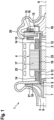
- the fluid flow machine 1 shown comprises a shaft 2 in which a compressor wheel 3 is arranged at one end and a turbine wheel 19 at the other end.
- the shaft 2 is rotated by means of an electric motor 4 in a rotational movement about its longitudinal axis A.
- the electric motor 4 comprises a winding 17 arranged around the shaft 2 and a permanent magnet 23 accommodated in the shaft 2. So that the shaft 2 can execute a rotary movement, it is rotatably mounted via two radial bearings 14.
- two axial bearings 15 are provided in the area of an axial bearing disk 18 connected to the shaft 2.
- the bearings 14, 15 are integrated in a motor housing 22 of the electric motor 4.
- the compressor wheel 3 is surrounded by a compressor housing 21 and the turbine wheel 19 is surrounded by a turbine housing 20.
- the compressor wheel 3 of the turbomachine 1 shown has several air ducts 7, 8 in a hub section 5, which is inserted into a hollow cylindrical shaft section 6.
- the air ducts 7, 8 connect the compressor inlet 9 with an annular space 10 on the side of the compressor wheel 3 facing away from the compressor inlet 9. This creates a
- Partial air flow from the compressor inlet 9 is fed into the annular space 10 so that the same air pressure prevails in both spaces. This means that the axial forces acting on the compressor wheel 3 cancel each other out. The bearing losses in the area of the axial bearings 15 are reduced accordingly.
- the shaft section 6 Since in the present case the radially extending air channels 8 are arranged in the region of the hub section 5 which is inserted into the hollow cylindrical shaft section 6, the shaft section 6 has air channels 11 arranged in overlap with the air channels 8.
- the turbomachine 1 shown has further air ducts 12,13.
- the air ducts 12,13 connect the annular space 10 with at least one bearing 14,15.
- at least one axially extending air duct 12 leads from the annular space 10 via the radial bearings 14 from the compressor side to the turbine side of the Turbomachine 1, so that the radial bearings 14 are cooled by the air supplied.
- the at least one air duct 12 is guided over an annular gap 16 between the winding 17 and the shaft 2, so that the electric motor 4 is also cooled.
- the at least one air duct 12 is connected to at least one radially extending air duct 13, which extends through the axial bearing disk 18 from radially inside to radially outside. This not only cools the axial bearings 15, but also increases the air pressure to the level in front of the turbine wheel 19.
- the air flow 24 leading through the air ducts 7, 8, 12, 13 is in the Fig.2 indicated by arrows.
Landscapes
- Engineering & Computer Science (AREA)
- General Engineering & Computer Science (AREA)
- Mechanical Engineering (AREA)
- Physics & Mathematics (AREA)
- Fluid Mechanics (AREA)
- Chemical & Material Sciences (AREA)
- Thermal Sciences (AREA)
- Combustion & Propulsion (AREA)
- Power Engineering (AREA)
- Chemical Kinetics & Catalysis (AREA)
- General Chemical & Material Sciences (AREA)
- Structures Of Non-Positive Displacement Pumps (AREA)
- Fuel Cell (AREA)
Claims (10)
- Machine à flux (1) pour l'alimentation en air d'un système de piles à combustible, comprenant au moins une roue de compresseur (3) reliée de manière solidaire en rotation à un arbre (2) ainsi qu'un moteur électrique (4) pour l'entraînement de l'arbre (2), la roue de compresseur (3) étant reliée de manière solidaire en rotation, par une section de moyeu (5), à une section d'arbre (6) de l'arbre (2), de préférence de forme cylindrique creuse, au moins un canal d'air (7, 8) étant formé dans la section de moyeu (5), par lequel une entrée de compresseur (9) est reliée à un espace annulaire (10) sur le côté de la roue de compresseur (3) opposé à l'entrée de compresseur (9),
caractérisé en ce que l'espace annulaire (10) sur le côté de la roue de compresseur (3) opposé à l'entrée de compresseur (9) est relié à au moins un palier (14, 15) de l'arbre (2) par au moins un autre canal d'air (12, 13), ledit au moins un autre canal d'air (12) étant guidé par un interstice annulaire (16) entre l'arbre (2) et un enroulement (17) du moteur électrique (3) entourant l'arbre (2). - Machine à flux (1) selon la revendication 1,
caractérisée en ce que la section de moyeu (5) présente au moins un canal d'air (7) s'étendant axialement. - Machine à flux (1) selon la revendication 1 ou la revendication 2,
caractérisée en ce que la section de moyeu (5) présente au moins un canal d'air (8) s'étendant essentiellement radialement. - Machine à flux (1) selon l'une des revendications précédentes, caractérisée en ce que la section de moyeu (5) est insérée, en particulier enfoncée, au moins par sections dans la section d'arbre (6) en forme de cylindre creux.
- Machine à flux (1) selon la revendication 3 ou la revendication 4,
caractérisée en ce que la section d'arbre (6) en forme de cylindre creux présente au moins un canal d'air (11) s'étendant sensiblement radialement, qui est agencée en recouvrement avec ledit au moins un canal d'air (8) s'étendant radialement de la section de moyeu (5). - Machine à flux (1) selon l'une des revendications précédentes, caractérisée en ce que ledit au moins un palier (14, 15) est réalisé sous forme de palier à air en feuille.
- Machine à flux (1) selon l'une des revendications précédentes,
caractérisée en ce que ledit au moins un autre canal d'air (13) est guidé à travers un disque de palier axial (18) à ventilation interne, solidaire en rotation de l'arbre (2), pour supporter une roue de turbine (19). - Machine à flux (1) selon l'une des revendications précédentes,
caractérisée en ce que les conduits d'air (7, 8, 12, 13) destinés à relier l'entrée du compresseur (9) sont aptes à être alimentés en air ambiant refroidi ou non. - Procédé de fonctionnement d'une turbomachine (1) selon l'une des revendications précédentes,
caractérisé en ce que les conduits d'air (7, 8, 12, 13) sont alimentés en air ambiant refroidi ou non refroidi. - Procédé selon la revendication 9,
caractérisé en ce que la pression de l'air de refroidissement est augmentée à l'aide d'un disque de palier axial (18) ventilé intérieurement, à travers lequel est guidé au moins un canal d'air (13).
Applications Claiming Priority (2)
| Application Number | Priority Date | Filing Date | Title |
|---|---|---|---|
| DE102019215337.2A DE102019215337A1 (de) | 2019-10-07 | 2019-10-07 | Strömungsmaschine, Verfahren zum Betreiben einer Strömungsmaschine |
| PCT/EP2020/073980 WO2021069143A1 (fr) | 2019-10-07 | 2020-08-27 | Turbomachine etprocédé de fonctionnement d'une turbomachine |
Publications (2)
| Publication Number | Publication Date |
|---|---|
| EP4041994A1 EP4041994A1 (fr) | 2022-08-17 |
| EP4041994B1 true EP4041994B1 (fr) | 2024-08-14 |
Family
ID=72340334
Family Applications (1)
| Application Number | Title | Priority Date | Filing Date |
|---|---|---|---|
| EP20765235.5A Active EP4041994B1 (fr) | 2019-10-07 | 2020-08-27 | Machine à flux pour l'alimentation en air d'un système de piles à combustible, procédé de fonctionnement d'une telle machine à flux |
Country Status (7)
| Country | Link |
|---|---|
| US (1) | US12123427B2 (fr) |
| EP (1) | EP4041994B1 (fr) |
| JP (1) | JP7387886B2 (fr) |
| KR (1) | KR20220071972A (fr) |
| CN (1) | CN114556754A (fr) |
| DE (1) | DE102019215337A1 (fr) |
| WO (1) | WO2021069143A1 (fr) |
Families Citing this family (4)
| Publication number | Priority date | Publication date | Assignee | Title |
|---|---|---|---|---|
| JP2023174295A (ja) * | 2022-05-27 | 2023-12-07 | 株式会社豊田自動織機 | 遠心圧縮機 |
| DE102022114460A1 (de) * | 2022-06-09 | 2023-12-14 | Zf Cv Systems Global Gmbh | Verdichter für ein Brennstoffzellensystem, und Brennstoffzellensystem mit selbigem |
| DE102023120734A1 (de) | 2023-08-04 | 2025-02-06 | Boge Kompressoren Otto Boge Gmbh & Co. Kg | Folienlager und Maschine, insbesondere Turbomaschine |
| JP2025181144A (ja) * | 2024-05-31 | 2025-12-11 | 三菱重工業株式会社 | 回転機械 |
Family Cites Families (11)
| Publication number | Priority date | Publication date | Assignee | Title |
|---|---|---|---|---|
| JP5016682B2 (ja) | 2007-01-19 | 2012-09-05 | ダイムラー・アクチェンゲゼルシャフト | 流体フロー機関 |
| EP2290241A1 (fr) * | 2009-07-13 | 2011-03-02 | Siemens Aktiengesellschaft | Ensemble de turbocompresseur avec un système de refroidissement |
| DE102012215895A1 (de) * | 2012-09-07 | 2014-03-13 | Robert Bosch Gmbh | Schaufelrad für eine Strömungsmaschine sowie Verfahren zum Herstellen eines Turbinenrads für eine Strömungsmaschine |
| DE102014018070A1 (de) * | 2014-12-09 | 2015-07-02 | Daimler Ag | Lagereinrichtung zum Lagern eines Rotors einer Strömungsmaschine |
| DE102014018096A1 (de) * | 2014-12-09 | 2015-07-02 | Daimler Ag | Strömungsmaschine für einen Energiewandler, insbesondere eine Brennstoffzelle |
| DE102015007379A1 (de) * | 2015-06-10 | 2016-01-21 | Daimler Ag | Strömungsmaschine für einen Energiewandler, insbesondere eine Brennstoffzelle |
| DE102017211943A1 (de) * | 2017-07-12 | 2019-01-17 | Bayerische Motoren Werke Aktiengesellschaft | Brennstoffzellenbetriebenes Kraftfahrzeug sowie Betriebsverfahren |
| DE102017211940A1 (de) * | 2017-07-12 | 2019-01-17 | Bayerische Motoren Werke Aktiengesellschaft | Brennstoffzellensystem für ein Kraftfahrzeug sowie Strömungsmaschine für ein Brennstoffzellensystem |
| DE102017216763A1 (de) * | 2017-09-21 | 2019-03-21 | Bayerische Motoren Werke Aktiengesellschaft | Verfahren zum Betrieb einer Strömungsmaschine sowie Strömungsmaschine |
| WO2019087970A1 (fr) | 2017-11-01 | 2019-05-09 | 株式会社Ihi | Compresseur centrifuge |
| US11131313B2 (en) * | 2019-05-10 | 2021-09-28 | Garrett Transportation I Inc | Single-stage compressor with bleed system for thrust load alleviation |
-
2019
- 2019-10-07 DE DE102019215337.2A patent/DE102019215337A1/de active Pending
-
2020
- 2020-08-27 US US17/766,901 patent/US12123427B2/en active Active
- 2020-08-27 WO PCT/EP2020/073980 patent/WO2021069143A1/fr not_active Ceased
- 2020-08-27 KR KR1020227014822A patent/KR20220071972A/ko active Pending
- 2020-08-27 JP JP2022520630A patent/JP7387886B2/ja active Active
- 2020-08-27 EP EP20765235.5A patent/EP4041994B1/fr active Active
- 2020-08-27 CN CN202080070470.9A patent/CN114556754A/zh active Pending
Also Published As
| Publication number | Publication date |
|---|---|
| US12123427B2 (en) | 2024-10-22 |
| EP4041994A1 (fr) | 2022-08-17 |
| WO2021069143A1 (fr) | 2021-04-15 |
| JP7387886B2 (ja) | 2023-11-28 |
| DE102019215337A1 (de) | 2021-04-08 |
| JP2022550594A (ja) | 2022-12-02 |
| CN114556754A (zh) | 2022-05-27 |
| US20240093695A1 (en) | 2024-03-21 |
| KR20220071972A (ko) | 2022-05-31 |
Similar Documents
| Publication | Publication Date | Title |
|---|---|---|
| EP4041994B1 (fr) | Machine à flux pour l'alimentation en air d'un système de piles à combustible, procédé de fonctionnement d'une telle machine à flux | |
| EP2600007B1 (fr) | Dispositif de système automobile et procédé de fonctionnement d'un dispositif de système automobile | |
| DE102012013048A1 (de) | Strömungsmaschine für einen Energiewandler sowie Brennstoffzelleneinrichtung mit einer solchen Strömungsmaschine | |
| EP2600015B1 (fr) | Turbocompresseur, système de piles à combustible | |
| DE102010035725A1 (de) | Aufladeeinrichtung für eine Energieumwandlungseinrichtung | |
| DE102011119881A1 (de) | Aufladeeinrichtung für eine Brennstoffzelle, insbesondere eines Kraftwagens | |
| DE102020205172A1 (de) | Strömungsmaschine, Verfahren zum Betreiben einer Strömungsmaschine | |
| WO2016091348A1 (fr) | Turbomachine pour un convertisseur d'énergie, en particulier une pile à combustible | |
| DE102012221303A1 (de) | Antriebseinrichtung mit einer Brennstoffzelle und einem Abgasturbolader | |
| DE102023117621A1 (de) | Aufladevorrichtung mit axiallager | |
| WO2021063600A1 (fr) | Palier à gaz axial | |
| DE102021203593A1 (de) | Strömungsmaschine, Brennstoffzellensystem mit Strömungsmaschine sowie Verfahren zum Betreiben einer Strömungsmaschine | |
| WO2011113465A1 (fr) | Dispositif de charge pour une pile à combustible | |
| DE102017212821A1 (de) | Turbomaschine, insbesondere für ein Brennstoffzellensystem | |
| WO2021018455A1 (fr) | Appareil d'alimentation en air | |
| DE102021202889A1 (de) | Gaszuführvorrichtung mit einer durch eine Gaslageranordnung gelagerten Welle | |
| DE102023104857B4 (de) | Aufladesystem einer Brennstoffzelle | |
| WO2021233751A1 (fr) | Rotor pour une unité d'alimentation en air d'une unité de pile à combustible et unité d'alimentation en air pour une unité de pile à combustible | |
| DE102019118539A1 (de) | Verdichter | |
| DE102011003509A1 (de) | Fliehkraftunterdruckpumpe und Verfahren zur Unterdruckerzeugung | |
| DE102022206534A1 (de) | Gasfördervorrichtung | |
| DE102023205270A1 (de) | Verdichter und Verfahren zum Betreiben eines Verdichters | |
| DE102023206401A1 (de) | Verdichter und Verfahren zum Betreiben eines Verdichters | |
| DE102023205768A1 (de) | Verfahren zum Betreiben einer thermischen Strömungsmaschine, thermische Strömungsmaschine | |
| DE102017212825A1 (de) | Turbomaschine, insbesondere für ein Brennstoffzellensystem |
Legal Events
| Date | Code | Title | Description |
|---|---|---|---|
| STAA | Information on the status of an ep patent application or granted ep patent |
Free format text: STATUS: UNKNOWN |
|
| STAA | Information on the status of an ep patent application or granted ep patent |
Free format text: STATUS: THE INTERNATIONAL PUBLICATION HAS BEEN MADE |
|
| PUAI | Public reference made under article 153(3) epc to a published international application that has entered the european phase |
Free format text: ORIGINAL CODE: 0009012 |
|
| STAA | Information on the status of an ep patent application or granted ep patent |
Free format text: STATUS: REQUEST FOR EXAMINATION WAS MADE |
|
| 17P | Request for examination filed |
Effective date: 20220509 |
|
| AK | Designated contracting states |
Kind code of ref document: A1 Designated state(s): AL AT BE BG CH CY CZ DE DK EE ES FI FR GB GR HR HU IE IS IT LI LT LU LV MC MK MT NL NO PL PT RO RS SE SI SK SM TR |
|
| DAV | Request for validation of the european patent (deleted) | ||
| DAX | Request for extension of the european patent (deleted) | ||
| STAA | Information on the status of an ep patent application or granted ep patent |
Free format text: STATUS: EXAMINATION IS IN PROGRESS |
|
| 17Q | First examination report despatched |
Effective date: 20230620 |
|
| GRAP | Despatch of communication of intention to grant a patent |
Free format text: ORIGINAL CODE: EPIDOSNIGR1 |
|
| STAA | Information on the status of an ep patent application or granted ep patent |
Free format text: STATUS: GRANT OF PATENT IS INTENDED |
|
| INTG | Intention to grant announced |
Effective date: 20240419 |
|
| GRAS | Grant fee paid |
Free format text: ORIGINAL CODE: EPIDOSNIGR3 |
|
| GRAA | (expected) grant |
Free format text: ORIGINAL CODE: 0009210 |
|
| STAA | Information on the status of an ep patent application or granted ep patent |
Free format text: STATUS: THE PATENT HAS BEEN GRANTED |
|
| AK | Designated contracting states |
Kind code of ref document: B1 Designated state(s): AL AT BE BG CH CY CZ DE DK EE ES FI FR GB GR HR HU IE IS IT LI LT LU LV MC MK MT NL NO PL PT RO RS SE SI SK SM TR |
|
| REG | Reference to a national code |
Ref country code: GB Ref legal event code: FG4D Free format text: NOT ENGLISH |
|
| REG | Reference to a national code |
Ref country code: CH Ref legal event code: EP |
|
| REG | Reference to a national code |
Ref country code: DE Ref legal event code: R096 Ref document number: 502020008882 Country of ref document: DE |
|
| REG | Reference to a national code |
Ref country code: IE Ref legal event code: FG4D Free format text: LANGUAGE OF EP DOCUMENT: GERMAN |
|
| REG | Reference to a national code |
Ref country code: LT Ref legal event code: MG9D |
|
| REG | Reference to a national code |
Ref country code: NL Ref legal event code: MP Effective date: 20240814 |
|
| PG25 | Lapsed in a contracting state [announced via postgrant information from national office to epo] |
Ref country code: NO Free format text: LAPSE BECAUSE OF FAILURE TO SUBMIT A TRANSLATION OF THE DESCRIPTION OR TO PAY THE FEE WITHIN THE PRESCRIBED TIME-LIMIT Effective date: 20241114 |
|
| PG25 | Lapsed in a contracting state [announced via postgrant information from national office to epo] |
Ref country code: NL Free format text: LAPSE BECAUSE OF FAILURE TO SUBMIT A TRANSLATION OF THE DESCRIPTION OR TO PAY THE FEE WITHIN THE PRESCRIBED TIME-LIMIT Effective date: 20240814 Ref country code: PT Free format text: LAPSE BECAUSE OF FAILURE TO SUBMIT A TRANSLATION OF THE DESCRIPTION OR TO PAY THE FEE WITHIN THE PRESCRIBED TIME-LIMIT Effective date: 20241216 Ref country code: PL Free format text: LAPSE BECAUSE OF FAILURE TO SUBMIT A TRANSLATION OF THE DESCRIPTION OR TO PAY THE FEE WITHIN THE PRESCRIBED TIME-LIMIT Effective date: 20240814 Ref country code: GR Free format text: LAPSE BECAUSE OF FAILURE TO SUBMIT A TRANSLATION OF THE DESCRIPTION OR TO PAY THE FEE WITHIN THE PRESCRIBED TIME-LIMIT Effective date: 20241115 Ref country code: FI Free format text: LAPSE BECAUSE OF FAILURE TO SUBMIT A TRANSLATION OF THE DESCRIPTION OR TO PAY THE FEE WITHIN THE PRESCRIBED TIME-LIMIT Effective date: 20240814 |
|
| PG25 | Lapsed in a contracting state [announced via postgrant information from national office to epo] |
Ref country code: BG Free format text: LAPSE BECAUSE OF FAILURE TO SUBMIT A TRANSLATION OF THE DESCRIPTION OR TO PAY THE FEE WITHIN THE PRESCRIBED TIME-LIMIT Effective date: 20240814 |
|
| PG25 | Lapsed in a contracting state [announced via postgrant information from national office to epo] |
Ref country code: LV Free format text: LAPSE BECAUSE OF FAILURE TO SUBMIT A TRANSLATION OF THE DESCRIPTION OR TO PAY THE FEE WITHIN THE PRESCRIBED TIME-LIMIT Effective date: 20240814 |
|
| PG25 | Lapsed in a contracting state [announced via postgrant information from national office to epo] |
Ref country code: IS Free format text: LAPSE BECAUSE OF FAILURE TO SUBMIT A TRANSLATION OF THE DESCRIPTION OR TO PAY THE FEE WITHIN THE PRESCRIBED TIME-LIMIT Effective date: 20241214 |
|
| PG25 | Lapsed in a contracting state [announced via postgrant information from national office to epo] |
Ref country code: HR Free format text: LAPSE BECAUSE OF FAILURE TO SUBMIT A TRANSLATION OF THE DESCRIPTION OR TO PAY THE FEE WITHIN THE PRESCRIBED TIME-LIMIT Effective date: 20240814 |
|
| PG25 | Lapsed in a contracting state [announced via postgrant information from national office to epo] |
Ref country code: RS Free format text: LAPSE BECAUSE OF FAILURE TO SUBMIT A TRANSLATION OF THE DESCRIPTION OR TO PAY THE FEE WITHIN THE PRESCRIBED TIME-LIMIT Effective date: 20241114 Ref country code: ES Free format text: LAPSE BECAUSE OF FAILURE TO SUBMIT A TRANSLATION OF THE DESCRIPTION OR TO PAY THE FEE WITHIN THE PRESCRIBED TIME-LIMIT Effective date: 20240814 |
|
| PG25 | Lapsed in a contracting state [announced via postgrant information from national office to epo] |
Ref country code: RS Free format text: LAPSE BECAUSE OF FAILURE TO SUBMIT A TRANSLATION OF THE DESCRIPTION OR TO PAY THE FEE WITHIN THE PRESCRIBED TIME-LIMIT Effective date: 20241114 Ref country code: PT Free format text: LAPSE BECAUSE OF FAILURE TO SUBMIT A TRANSLATION OF THE DESCRIPTION OR TO PAY THE FEE WITHIN THE PRESCRIBED TIME-LIMIT Effective date: 20241216 Ref country code: PL Free format text: LAPSE BECAUSE OF FAILURE TO SUBMIT A TRANSLATION OF THE DESCRIPTION OR TO PAY THE FEE WITHIN THE PRESCRIBED TIME-LIMIT Effective date: 20240814 Ref country code: NO Free format text: LAPSE BECAUSE OF FAILURE TO SUBMIT A TRANSLATION OF THE DESCRIPTION OR TO PAY THE FEE WITHIN THE PRESCRIBED TIME-LIMIT Effective date: 20241114 Ref country code: NL Free format text: LAPSE BECAUSE OF FAILURE TO SUBMIT A TRANSLATION OF THE DESCRIPTION OR TO PAY THE FEE WITHIN THE PRESCRIBED TIME-LIMIT Effective date: 20240814 Ref country code: LV Free format text: LAPSE BECAUSE OF FAILURE TO SUBMIT A TRANSLATION OF THE DESCRIPTION OR TO PAY THE FEE WITHIN THE PRESCRIBED TIME-LIMIT Effective date: 20240814 Ref country code: IS Free format text: LAPSE BECAUSE OF FAILURE TO SUBMIT A TRANSLATION OF THE DESCRIPTION OR TO PAY THE FEE WITHIN THE PRESCRIBED TIME-LIMIT Effective date: 20241214 Ref country code: HR Free format text: LAPSE BECAUSE OF FAILURE TO SUBMIT A TRANSLATION OF THE DESCRIPTION OR TO PAY THE FEE WITHIN THE PRESCRIBED TIME-LIMIT Effective date: 20240814 Ref country code: GR Free format text: LAPSE BECAUSE OF FAILURE TO SUBMIT A TRANSLATION OF THE DESCRIPTION OR TO PAY THE FEE WITHIN THE PRESCRIBED TIME-LIMIT Effective date: 20241115 Ref country code: FI Free format text: LAPSE BECAUSE OF FAILURE TO SUBMIT A TRANSLATION OF THE DESCRIPTION OR TO PAY THE FEE WITHIN THE PRESCRIBED TIME-LIMIT Effective date: 20240814 Ref country code: ES Free format text: LAPSE BECAUSE OF FAILURE TO SUBMIT A TRANSLATION OF THE DESCRIPTION OR TO PAY THE FEE WITHIN THE PRESCRIBED TIME-LIMIT Effective date: 20240814 Ref country code: BG Free format text: LAPSE BECAUSE OF FAILURE TO SUBMIT A TRANSLATION OF THE DESCRIPTION OR TO PAY THE FEE WITHIN THE PRESCRIBED TIME-LIMIT Effective date: 20240814 |
|
| REG | Reference to a national code |
Ref country code: CH Ref legal event code: PL |
|
| PG25 | Lapsed in a contracting state [announced via postgrant information from national office to epo] |
Ref country code: RO Free format text: LAPSE BECAUSE OF FAILURE TO SUBMIT A TRANSLATION OF THE DESCRIPTION OR TO PAY THE FEE WITHIN THE PRESCRIBED TIME-LIMIT Effective date: 20240814 Ref country code: SM Free format text: LAPSE BECAUSE OF FAILURE TO SUBMIT A TRANSLATION OF THE DESCRIPTION OR TO PAY THE FEE WITHIN THE PRESCRIBED TIME-LIMIT Effective date: 20240814 Ref country code: DK Free format text: LAPSE BECAUSE OF FAILURE TO SUBMIT A TRANSLATION OF THE DESCRIPTION OR TO PAY THE FEE WITHIN THE PRESCRIBED TIME-LIMIT Effective date: 20240814 |
|
| PG25 | Lapsed in a contracting state [announced via postgrant information from national office to epo] |
Ref country code: LU Free format text: LAPSE BECAUSE OF NON-PAYMENT OF DUE FEES Effective date: 20240827 |
|
| PG25 | Lapsed in a contracting state [announced via postgrant information from national office to epo] |
Ref country code: CH Free format text: LAPSE BECAUSE OF NON-PAYMENT OF DUE FEES Effective date: 20240831 Ref country code: EE Free format text: LAPSE BECAUSE OF FAILURE TO SUBMIT A TRANSLATION OF THE DESCRIPTION OR TO PAY THE FEE WITHIN THE PRESCRIBED TIME-LIMIT Effective date: 20240814 |
|
| PG25 | Lapsed in a contracting state [announced via postgrant information from national office to epo] |
Ref country code: CZ Free format text: LAPSE BECAUSE OF FAILURE TO SUBMIT A TRANSLATION OF THE DESCRIPTION OR TO PAY THE FEE WITHIN THE PRESCRIBED TIME-LIMIT Effective date: 20240814 |
|
| PG25 | Lapsed in a contracting state [announced via postgrant information from national office to epo] |
Ref country code: SK Free format text: LAPSE BECAUSE OF FAILURE TO SUBMIT A TRANSLATION OF THE DESCRIPTION OR TO PAY THE FEE WITHIN THE PRESCRIBED TIME-LIMIT Effective date: 20240814 Ref country code: IT Free format text: LAPSE BECAUSE OF FAILURE TO SUBMIT A TRANSLATION OF THE DESCRIPTION OR TO PAY THE FEE WITHIN THE PRESCRIBED TIME-LIMIT Effective date: 20240814 |
|
| REG | Reference to a national code |
Ref country code: DE Ref legal event code: R097 Ref document number: 502020008882 Country of ref document: DE |
|
| PLBE | No opposition filed within time limit |
Free format text: ORIGINAL CODE: 0009261 |
|
| STAA | Information on the status of an ep patent application or granted ep patent |
Free format text: STATUS: NO OPPOSITION FILED WITHIN TIME LIMIT |
|
| REG | Reference to a national code |
Ref country code: BE Ref legal event code: MM Effective date: 20240831 |
|
| PG25 | Lapsed in a contracting state [announced via postgrant information from national office to epo] |
Ref country code: MC Free format text: LAPSE BECAUSE OF FAILURE TO SUBMIT A TRANSLATION OF THE DESCRIPTION OR TO PAY THE FEE WITHIN THE PRESCRIBED TIME-LIMIT Effective date: 20240814 |
|
| PG25 | Lapsed in a contracting state [announced via postgrant information from national office to epo] |
Ref country code: BE Free format text: LAPSE BECAUSE OF NON-PAYMENT OF DUE FEES Effective date: 20240831 |
|
| 26N | No opposition filed |
Effective date: 20250515 |
|
| GBPC | Gb: european patent ceased through non-payment of renewal fee |
Effective date: 20241114 |
|
| PG25 | Lapsed in a contracting state [announced via postgrant information from national office to epo] |
Ref country code: IE Free format text: LAPSE BECAUSE OF NON-PAYMENT OF DUE FEES Effective date: 20240827 |
|
| PG25 | Lapsed in a contracting state [announced via postgrant information from national office to epo] |
Ref country code: SE Free format text: LAPSE BECAUSE OF FAILURE TO SUBMIT A TRANSLATION OF THE DESCRIPTION OR TO PAY THE FEE WITHIN THE PRESCRIBED TIME-LIMIT Effective date: 20240814 |
|
| PG25 | Lapsed in a contracting state [announced via postgrant information from national office to epo] |
Ref country code: GB Free format text: LAPSE BECAUSE OF NON-PAYMENT OF DUE FEES Effective date: 20241114 |
|
| PGFP | Annual fee paid to national office [announced via postgrant information from national office to epo] |
Ref country code: FR Payment date: 20250821 Year of fee payment: 6 Ref country code: AT Payment date: 20251020 Year of fee payment: 5 |
|
| PGFP | Annual fee paid to national office [announced via postgrant information from national office to epo] |
Ref country code: DE Payment date: 20251021 Year of fee payment: 6 |
|
| PG25 | Lapsed in a contracting state [announced via postgrant information from national office to epo] |
Ref country code: CY Free format text: LAPSE BECAUSE OF FAILURE TO SUBMIT A TRANSLATION OF THE DESCRIPTION OR TO PAY THE FEE WITHIN THE PRESCRIBED TIME-LIMIT; INVALID AB INITIO Effective date: 20200827 |
|
| PG25 | Lapsed in a contracting state [announced via postgrant information from national office to epo] |
Ref country code: HU Free format text: LAPSE BECAUSE OF FAILURE TO SUBMIT A TRANSLATION OF THE DESCRIPTION OR TO PAY THE FEE WITHIN THE PRESCRIBED TIME-LIMIT; INVALID AB INITIO Effective date: 20200827 |