EP4042010B1 - Pumping unit for feeding a fluid, in particular fuel, preferably diesel fuel, to a user appliance, in particular an internal combustion engine - Google Patents
Pumping unit for feeding a fluid, in particular fuel, preferably diesel fuel, to a user appliance, in particular an internal combustion engine Download PDFInfo
- Publication number
- EP4042010B1 EP4042010B1 EP20780212.5A EP20780212A EP4042010B1 EP 4042010 B1 EP4042010 B1 EP 4042010B1 EP 20780212 A EP20780212 A EP 20780212A EP 4042010 B1 EP4042010 B1 EP 4042010B1
- Authority
- EP
- European Patent Office
- Prior art keywords
- pumping unit
- fluid
- feeding
- fuel
- cylinder
- Prior art date
- Legal status (The legal status is an assumption and is not a legal conclusion. Google has not performed a legal analysis and makes no representation as to the accuracy of the status listed.)
- Active
Links
Images


Classifications
-
- F—MECHANICAL ENGINEERING; LIGHTING; HEATING; WEAPONS; BLASTING
- F02—COMBUSTION ENGINES; HOT-GAS OR COMBUSTION-PRODUCT ENGINE PLANTS
- F02M—SUPPLYING COMBUSTION ENGINES IN GENERAL WITH COMBUSTIBLE MIXTURES OR CONSTITUENTS THEREOF
- F02M59/00—Pumps specially adapted for fuel-injection and not provided for in groups F02M39/00 -F02M57/00, e.g. rotary cylinder-block type of pumps
- F02M59/44—Details, components parts, or accessories not provided for in, or of interest apart from, the apparatus of groups F02M59/02 - F02M59/42; Pumps having transducers, e.g. to measure displacement of pump rack or piston
- F02M59/46—Valves
- F02M59/464—Inlet valves of the check valve type
Definitions
- the present invention relates to a pumping unit for feeding a fluid, in particular fuel, preferably diesel fuel, to a user appliance, in particular an internal combustion engine.
- a fluid in particular fuel, preferably diesel fuel
- a user appliance in particular an internal combustion engine.
- the present invention has a particularly advantageous application in the feeding of fuel, preferably diesel fuel, to an internal combustion engine, to which the description below specifically refers without thereby losing its general character.
- fuel preferably diesel fuel
- the pumping unit comprises a high-pressure pump for feeding fuel to an internal combustion engine; and a low pressure or pre-feed pump for feeding fuel from a storage tank to the said high-pressure pump.
- the high-pressure pump is a piston pump comprising a pump body; at least one cylinder formed in the pump body; a piston slidably engaged inside the cylinder; and an actuating device for displacing the cylinder with an alternating rectilinear movement comprising an intake stroke for drawing the fuel into the cylinder and a delivery stroke for supplying the fuel to the internal combustion engine.
- the high-pressure pump further comprises an intake valve for selectively controlling feeding of the fuel into the cylinder; and a delivery valve for selectively controlling feeding of the fuel to the internal combustion engine.
- the intake valve comprises a valve body with a cylindrical shape, mounted and fixed inside the pump body, and a closing member engaged slidably through the valve body so as to be displaced between an open position and a closed position of the cylinder.
- the closing member When the closing member is arranged in its closed position, the closing member and the valve body are engaged with each other in a fluid-tight manner in a sealing zone defined by respective engaging surfaces.
- each piston causes closing of the associated intake valve.
- a part of fuel compressed by the piston exits the cylinder between the valve body and the closing member.
- the known pumping units of the type described above have a number of drawbacks mainly resulting from the fact that the fuel exiting the cylinder during the delivery stroke of the piston is subject, in the aforementioned sealing zone, to cavitation effects, namely the formation of vapour bubbles which, following the subsequent renewed filling of the cylinder with fuel supplied by the pre-feed pump, implode, generating noise, causing wear and erosion of the said engaging surfaces and therefore adversely affecting the fluid-tight connection between the closing member and the valve body.
- An example of a known inlet valve for a fuel pump is shown in document ITMI20091918 A1 .
- the object of the present invention is to provide a pumping unit for feeding a fluid, in particular fuel, preferably diesel fuel, to a user appliance, in particular an internal combustion engine, which does not have the aforementioned drawbacks and is simple and inexpensive to produce.
- a fluid in particular fuel, preferably diesel fuel
- a pumping unit for feeding a fluid, in particular fuel, preferably diesel fuel, to a user appliance, in particular an internal combustion engine is provided, as claimed in the accompanying claims.
- a pumping unit for feeding fuel, preferably diesel fuel, to an internal combustion engine (not shown).
- the pumping unit 1 comprises a high-pressure pump 2 for feeding the fuel to the said internal combustion engine (not shown); and a low-pressure or pre-feed pump 3 for feeding the fuel from a known storage tank (not shown) to said pump 2.
- the high-pressure pump 2 is a piston pump and has a pump body 4 comprising a support housing 5 which is provided with a central hole 6 having a longitudinal axis 7 and is also provided with at least one side hole 8 (normally a plurality of holes 8 uniformly distributed around the axis 7) having a longitudinal axis 9 transverse to the axis 7 and extending radially towards the outside of the casing 5 from the said hole 6.
- Each hole 8 is closed by a head-piece 10 which is arranged in contact with the housing 5 and has a lug 11 projecting inside the hole 8 coaxially with the axis 9.
- the head-piece 10 has a central hole 12 which is formed through the head-piece 10 coaxially with the axis 9 and comprises a wider portion 17a and a narrower portion 13b which are aligned with each other along said axis 9.
- the portion 13b faces the hole 6 and defines a cylinder 14 of the piston pump 2.
- the cylinder 14 is slidably engaged by a piston 15 movable, as a result of the thrust of an actuating device 16, with an alternating rectilinear movement comprising an intake stroke for drawing the fuel into the cylinder 14 and a delivery stroke for supplying the fuel to the said internal combustion engine (not shown).
- the device 16 comprises a tubular sleeve 17 which is slidably engaged inside the hole 8 coaxially with the axis 9, extends around the cylinder 14 and has an inner annular flange 18 which projects radially from an inner surface of the sleeve 17 and divides said sleeve 17 into two cylindrical portions 19, 20, the portion 19 of which faces the hole 6.
- the device 16 also has a tappet system 21 comprising a coupling block 27 with a substantially cylindrical shape, which is locked by means of interference inside the portion 19, is arranged in contact with the flange 18 and supports a tappet system roller 23.
- the roller 23 projects from the block 22 towards the hole 6 and is rotatably coupled with the block 23 so as to rotate, relative to said block 22, about its longitudinal axis 24 substantially perpendicular to the axis 9.
- the flange 18 supports an annular disk 25 which extends around the piston 15, is inserted inside the portion 20 of the sleeve 17 coaxially with the axis 9 and has an outer perimetral edge axially facing the flange 18 and an inner perimetral edge axially facing a head of said piston 15.
- the device 16 also comprises a compression spring 26 which is mounted between the lug 11 and the sleeve 17 coaxially with the axis 9 and is arranged between the head-piece 10 and the disk 25 so as to displace, and normally keep, the disk 25 in contact with the flange 18 and the roller 23 in contact with a cam 27 formed on an outer surface of an intermediate portion of a transmission shaft mounted through the hole 6 so as to rotate, relative to the housing 5, about the axis 7.
- a compression spring 26 which is mounted between the lug 11 and the sleeve 17 coaxially with the axis 9 and is arranged between the head-piece 10 and the disk 25 so as to displace, and normally keep, the disk 25 in contact with the flange 18 and the roller 23 in contact with a cam 27 formed on an outer surface of an intermediate portion of a transmission shaft mounted through the hole 6 so as to rotate, relative to the housing 5, about the axis 7.
- the head-piece 10 houses internally an intake valve 29 for drawing the fuel into the cylinder 14 and a delivery valve 30 for supplying the fuel to the internal combustion engine (not shown).
- the valve 29 is mounted inside the wider portion 13a of the hole 12 and comprises a valve body 31 with a cylindrical shape which extends around the axis 9 and is axially locked against an annular shoulder 32 defined between the portions 13a and 13b by a closing lid 33 screwed into the said portion 13a.
- the valve 29 also comprises a closing member 34 mounted though the valve body 31 so as to be displaced between a closed position, in which the closing member 34 engages in a fluid-tight manner with the valve body 31 in a sealing zone 35 so as to close the cylinder 14, and an open position.
- sealing zone 35 may have the form of a circumferential line or a frustoconical surface.
- the closing member 34 is displaced, and normally kept, in its closed position by a spring 36 arranged between the valve body 31 and an annular disc 37 mounted on the closing member 34 transversely with respect to the axis 9.
- the valve body 31 has a plurality of feeder holes 38 which are distributed around the axis 9 and have, in the case in question, respective longitudinal axes 39 which are substantially radial and transverse to the axis 9.
- the axes 39 of the holes 38 are inclined with respect to the axis 9 and directed towards the cylinder 14.
- the valve body 31 defines, together with the closing member 34, an intake chamber 49 configured so as to have a wider portion 41 and a narrower portion 42 arranged in succession and in this order from the outlet of the holes 38 to the zone 35.
- the fuel is fed firstly through the portion 41 and then through the portion 42, which has a through cross-section smaller than a through cross-section of the said portion 41.
- valve body 31 is incorporated in the head-piece 10 and made as one piece with the said head-piece 10 and in that the axes 39 of the holes 38 are inclined with respect to the axis 9.
- the fuel is fed firstly though the portion 41 and then through the portion 42 and finally into the cylinder 14.
- the pumping unit 1 has a number of advantages mainly resulting from the fact the configuration of the intake chamber 40 is such that:
Landscapes
- Engineering & Computer Science (AREA)
- Chemical & Material Sciences (AREA)
- Combustion & Propulsion (AREA)
- Mechanical Engineering (AREA)
- General Engineering & Computer Science (AREA)
- Fuel-Injection Apparatus (AREA)
- Liquid Carbonaceous Fuels (AREA)
Description
- The present invention relates to a pumping unit for feeding a fluid, in particular fuel, preferably diesel fuel, to a user appliance, in particular an internal combustion engine.
- The present invention has a particularly advantageous application in the feeding of fuel, preferably diesel fuel, to an internal combustion engine, to which the description below specifically refers without thereby losing its general character.
- The pumping unit comprises a high-pressure pump for feeding fuel to an internal combustion engine; and a low pressure or pre-feed pump for feeding fuel from a storage tank to the said high-pressure pump.
- The high-pressure pump is a piston pump comprising a pump body; at least one cylinder formed in the pump body; a piston slidably engaged inside the cylinder; and an actuating device for displacing the cylinder with an alternating rectilinear movement comprising an intake stroke for drawing the fuel into the cylinder and a delivery stroke for supplying the fuel to the internal combustion engine.
- The high-pressure pump further comprises an intake valve for selectively controlling feeding of the fuel into the cylinder; and a delivery valve for selectively controlling feeding of the fuel to the internal combustion engine.
- The intake valve comprises a valve body with a cylindrical shape, mounted and fixed inside the pump body, and a closing member engaged slidably through the valve body so as to be displaced between an open position and a closed position of the cylinder.
- When the closing member is arranged in its closed position, the closing member and the valve body are engaged with each other in a fluid-tight manner in a sealing zone defined by respective engaging surfaces.
- During use, the delivery stroke of each piston causes closing of the associated intake valve. During closure of the intake valve, a part of fuel compressed by the piston exits the cylinder between the valve body and the closing member.
- The known pumping units of the type described above have a number of drawbacks mainly resulting from the fact that the fuel exiting the cylinder during the delivery stroke of the piston is subject, in the aforementioned sealing zone, to cavitation effects, namely the formation of vapour bubbles which, following the subsequent renewed filling of the cylinder with fuel supplied by the pre-feed pump, implode, generating noise, causing wear and erosion of the said engaging surfaces and therefore adversely affecting the fluid-tight connection between the closing member and the valve body. An example of a known inlet valve for a fuel pump is shown in document
ITMI20091918 A1 - The object of the present invention is to provide a pumping unit for feeding a fluid, in particular fuel, preferably diesel fuel, to a user appliance, in particular an internal combustion engine, which does not have the aforementioned drawbacks and is simple and inexpensive to produce.
- According to the present invention a pumping unit for feeding a fluid, in particular fuel, preferably diesel fuel, to a user appliance, in particular an internal combustion engine is provided, as claimed in the accompanying claims.
- The present invention will now be described with reference to the accompanying drawings which illustrate a non-limiting example of embodiment thereof, in which:
-
Figure 1 is a first schematic cross-sectional view, with parts removed for greater clarity, of a preferred embodiment of the pumping unit according to the present invention; -
Figure 2 is a schematic cross-sectional view, with parts removed for greater clarity, of the pumping unit according toFigure 1 ; -
Figure 3 is a schematic cross-sectional view, on a larger scale, of a detail of the pumping unit shown inFigures 1 and2 ; -
Figure 4 is a schematic cross-sectional view, with parts removed for greater clarity, of a variant of the pumping unit according toFigures 1 and2 ; and -
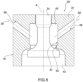
Figure 5 is a schematic cross-sectional view, on a larger scale, of a detail of the pumping unit shown inFigure 4 . - With reference to
Figures 1 and2 , 1 denotes in its entirety, a pumping unit for feeding fuel, preferably diesel fuel, to an internal combustion engine (not shown). - The
pumping unit 1 comprises a high-pressure pump 2 for feeding the fuel to the said internal combustion engine (not shown); and a low-pressure orpre-feed pump 3 for feeding the fuel from a known storage tank (not shown) to saidpump 2. - The high-
pressure pump 2 is a piston pump and has apump body 4 comprising asupport housing 5 which is provided with acentral hole 6 having alongitudinal axis 7 and is also provided with at least one side hole 8 (normally a plurality ofholes 8 uniformly distributed around the axis 7) having alongitudinal axis 9 transverse to theaxis 7 and extending radially towards the outside of thecasing 5 from thesaid hole 6. - Each
hole 8 is closed by a head-piece 10 which is arranged in contact with thehousing 5 and has alug 11 projecting inside thehole 8 coaxially with theaxis 9. - The head-
piece 10 has a central hole 12 which is formed through the head-piece 10 coaxially with theaxis 9 and comprises a wider portion 17a and anarrower portion 13b which are aligned with each other along saidaxis 9. - The
portion 13b faces thehole 6 and defines acylinder 14 of thepiston pump 2. - The
cylinder 14 is slidably engaged by apiston 15 movable, as a result of the thrust of anactuating device 16, with an alternating rectilinear movement comprising an intake stroke for drawing the fuel into thecylinder 14 and a delivery stroke for supplying the fuel to the said internal combustion engine (not shown). - The
device 16 comprises atubular sleeve 17 which is slidably engaged inside thehole 8 coaxially with theaxis 9, extends around thecylinder 14 and has an innerannular flange 18 which projects radially from an inner surface of thesleeve 17 and divides saidsleeve 17 into twocylindrical portions portion 19 of which faces thehole 6. - The
device 16 also has atappet system 21 comprising acoupling block 27 with a substantially cylindrical shape, which is locked by means of interference inside theportion 19, is arranged in contact with theflange 18 and supports atappet system roller 23. - The
roller 23 projects from theblock 22 towards thehole 6 and is rotatably coupled with theblock 23 so as to rotate, relative to saidblock 22, about itslongitudinal axis 24 substantially perpendicular to theaxis 9. - The
flange 18 supports anannular disk 25 which extends around thepiston 15, is inserted inside theportion 20 of thesleeve 17 coaxially with theaxis 9 and has an outer perimetral edge axially facing theflange 18 and an inner perimetral edge axially facing a head of saidpiston 15. - The
device 16 also comprises acompression spring 26 which is mounted between thelug 11 and thesleeve 17 coaxially with theaxis 9 and is arranged between the head-piece 10 and thedisk 25 so as to displace, and normally keep, thedisk 25 in contact with theflange 18 and theroller 23 in contact with acam 27 formed on an outer surface of an intermediate portion of a transmission shaft mounted through thehole 6 so as to rotate, relative to thehousing 5, about theaxis 7. - The head-
piece 10 houses internally anintake valve 29 for drawing the fuel into thecylinder 14 and adelivery valve 30 for supplying the fuel to the internal combustion engine (not shown). - The
valve 29 is mounted inside thewider portion 13a of the hole 12 and comprises avalve body 31 with a cylindrical shape which extends around theaxis 9 and is axially locked against anannular shoulder 32 defined between theportions closing lid 33 screwed into thesaid portion 13a. - The
valve 29 also comprises aclosing member 34 mounted though thevalve body 31 so as to be displaced between a closed position, in which theclosing member 34 engages in a fluid-tight manner with thevalve body 31 in asealing zone 35 so as to close thecylinder 14, and an open position. - In connection with the above description it should be pointed out that the
sealing zone 35 may have the form of a circumferential line or a frustoconical surface. - The
closing member 34 is displaced, and normally kept, in its closed position by aspring 36 arranged between thevalve body 31 and anannular disc 37 mounted on theclosing member 34 transversely with respect to theaxis 9. - In accordance with that shown in
Figure 3 , thevalve body 31 has a plurality offeeder holes 38 which are distributed around theaxis 9 and have, in the case in question, respectivelongitudinal axes 39 which are substantially radial and transverse to theaxis 9. - According to a variant (not shown), the
axes 39 of theholes 38 are inclined with respect to theaxis 9 and directed towards thecylinder 14. - The
valve body 31 defines, together with theclosing member 34, an intake chamber 49 configured so as to have awider portion 41 and anarrower portion 42 arranged in succession and in this order from the outlet of theholes 38 to thezone 35. - In other words, at the outlet of the
holes 38, the fuel is fed firstly through theportion 41 and then through theportion 42, which has a through cross-section smaller than a through cross-section of thesaid portion 41. - The variant shown in
Figures 4 and5 differs from that shown in the preceding figures in that, in it, thevalve body 31 is incorporated in the head-piece 10 and made as one piece with the said head-piece 10 and in that theaxes 39 of theholes 38 are inclined with respect to theaxis 9. - In this case also, at the outlet of the
holes 38, the fuel is fed firstly though theportion 41 and then through theportion 42 and finally into thecylinder 14. - The
pumping unit 1 has a number of advantages mainly resulting from the fact the configuration of theintake chamber 40 is such that: - the cavitation affecting the fuel exiting from the
cylinder 14 during the delivery stroke of thepiston 15 is concentrated in thewider portion 41; - cavitation is prevented from being concentrated in the
sealing zone 35; - wear of the
valve body 31 and theclosing member 34 is avoided in thezone 35; and - correct fluid-tight engagement between the
valve body 31 and theclosing member 31 is ensured when theclosing member 34 is arranged in its closed position.
Claims (7)
- Pumping unit for feeding a fluid, in particular fuel, preferably diesel fuel, to a user appliance, in particular an internal combustion engine, the pumping unit comprising a high-pressure pump (2) for feeding the fluid to the user appliance; and a pre-feed pump (3) for feeding the fluid to the high-pressure pump (2); the high-pressure pump (2) comprising, in turn, a pump body (4); at least one cylinder (14) formed in the pump body (4); a piston (15) slidably engaged inside the cylinder (14); and an intake valve (29) for selectively controlling the feeding of the fluid to the cylinder (14); the intake valve (29) comprising, in turn, a valve body (31), a closing member (34) slidably engaged through the valve body (31), an intake chamber (40) defined between the valve body (31) and the closing member (34) and at least one feeder hole (38) formed through the valve body (31) for feeding the fluid into the intake chamber (40); and being characterized in that the intake chamber (40) is configured so as to have a wider portion (41) and a narrower portion (42) arranged in succession and in this order from the outlet of the feeder holes (38) to the cylinder (14).
- Pumping unit according to Claim 1, wherein the closing member (34) is movable between a closed position, in which the closing member (34) is engaged in a fluid-tight manner with the valve body (31) in a sealing zone (34), and an open position; the wider portion (41) and the narrower portion (42) being arranged in succession and in this order from the outlet of the feeder holes (38) to the sealing zone (35).
- Pumping unit according to Claim 1 or 2, wherein the wider portion (41) has a through cross-section larger than a through cross-section of the narrower portion (42).
- Pumping unit according to any one of the preceding claims, wherein the valve body (31) is mounted and locked inside the pump body (4).
- Pumping unit according to any one of Claims 1 to 3, wherein the valve body (31) is incorporated in - and made as one piece with - the pump body (4).
- Pumping unit according to any one of the preceding claims, wherein each feeder hole (38) has a longitudinal axis (39) arranged transversely with respect to a longitudinal axis (9) of the cylinder (14).
- Pumping unit according to any one of Claims 1 to 5, wherein each feeder hole (38) has a longitudinal axis (39) inclined with respect to a longitudinal axis (9) of the cylinder (14).
Applications Claiming Priority (2)
| Application Number | Priority Date | Filing Date | Title |
|---|---|---|---|
| IT102019000018122A IT201900018122A1 (en) | 2019-10-07 | 2019-10-07 | PUMPING GROUP TO FEED A FLUID, IN PARTICULAR FUEL, PREFERABLY DIESEL, TO A USER, IN PARTICULAR AN INTERNAL COMBUSTION ENGINE |
| PCT/EP2020/077363 WO2021069276A1 (en) | 2019-10-07 | 2020-09-30 | Pumping unit for feeding a fluid, in particular fuel, preferably diesel fuel, to a user appliance, in particular an internal combustion engine |
Publications (2)
| Publication Number | Publication Date |
|---|---|
| EP4042010A1 EP4042010A1 (en) | 2022-08-17 |
| EP4042010B1 true EP4042010B1 (en) | 2023-12-20 |
Family
ID=69701267
Family Applications (1)
| Application Number | Title | Priority Date | Filing Date |
|---|---|---|---|
| EP20780212.5A Active EP4042010B1 (en) | 2019-10-07 | 2020-09-30 | Pumping unit for feeding a fluid, in particular fuel, preferably diesel fuel, to a user appliance, in particular an internal combustion engine |
Country Status (4)
| Country | Link |
|---|---|
| EP (1) | EP4042010B1 (en) |
| CN (1) | CN114514372B (en) |
| IT (1) | IT201900018122A1 (en) |
| WO (1) | WO2021069276A1 (en) |
Family Cites Families (12)
| Publication number | Priority date | Publication date | Assignee | Title |
|---|---|---|---|---|
| JP4605092B2 (en) * | 2006-05-18 | 2011-01-05 | 株式会社デンソー | Fuel supply pump |
| DE102007012705A1 (en) * | 2007-03-16 | 2008-09-18 | Robert Bosch Gmbh | High-pressure pump for conveying fuel with a torsion-decoupled compression spring element in the plunger device |
| JP5039507B2 (en) * | 2007-10-31 | 2012-10-03 | 日立オートモティブシステムズ株式会社 | High pressure fuel supply pump and method of manufacturing the same |
| DE102008042650A1 (en) * | 2008-10-07 | 2010-04-08 | Robert Bosch Gmbh | Radial piston pump for supplying internal combustion engine with fuel, has high pressure valve provided with closing element that is pressed at limiting surface of insert body or pressed at housing connected with insert body |
| IT1396590B1 (en) * | 2009-11-03 | 2012-12-14 | Bosch Gmbh Robert | PUMPING GROUP FOR FUEL SUPPLEMENTATION, PREFERABLY GASOIL, TO AN INTERNAL COMBUSTION ENGINE |
| CN102465801B (en) * | 2010-11-18 | 2014-08-13 | 博世汽车柴油系统有限公司 | High-pressure fuel pump |
| CN102619660B (en) * | 2011-01-28 | 2015-06-24 | 株式会社电装 | High pressure pump |
| ITMI20120243A1 (en) * | 2012-02-17 | 2013-08-18 | Bosch Gmbh Robert | INTAKE VALVE AND PUMPING GROUP FOR FUEL SUPPLEMENT, PREFERIBLY GASOIL, TO AN INTERNAL COMBUSTION ENGINE |
| DE102012210018A1 (en) * | 2012-06-14 | 2013-12-19 | Robert Bosch Gmbh | Suction valve for high pressure pump of fuel injection system, has collar-shaped extension that is provided with valve structure guide surface that is in contact with guide surface of supporting element |
| ITUA20164365A1 (en) * | 2016-06-14 | 2017-12-14 | Bosch Gmbh Robert | PUMPING GROUP FOR FUEL SUPPLEMENTATION, PREFERABLY GASOIL, TO AN INTERNAL COMBUSTION ENGINE |
| IT201600131338A1 (en) * | 2016-12-27 | 2018-06-27 | Bosch Gmbh Robert | PUMPING GROUP FOR FUEL SUPPLEMENTATION, PREFERABLY GASOIL, TO AN INTERNAL COMBUSTION ENGINE |
| IT201700030556A1 (en) * | 2017-03-20 | 2018-09-20 | Bosch Gmbh Robert | METHOD AND PUMPING GROUP FOR FOOD FUEL, PREFERIBLY GASOIL, TO AN INTERNAL COMBUSTION ENGINE |
-
2019
- 2019-10-07 IT IT102019000018122A patent/IT201900018122A1/en unknown
-
2020
- 2020-09-30 WO PCT/EP2020/077363 patent/WO2021069276A1/en not_active Ceased
- 2020-09-30 EP EP20780212.5A patent/EP4042010B1/en active Active
- 2020-09-30 CN CN202080070478.5A patent/CN114514372B/en active Active
Also Published As
| Publication number | Publication date |
|---|---|
| EP4042010A1 (en) | 2022-08-17 |
| IT201900018122A1 (en) | 2021-04-07 |
| CN114514372A (en) | 2022-05-17 |
| CN114514372B (en) | 2024-11-26 |
| WO2021069276A1 (en) | 2021-04-15 |
Similar Documents
| Publication | Publication Date | Title |
|---|---|---|
| JP4453028B2 (en) | High pressure fuel pump | |
| US9856844B2 (en) | Fuel pump for a direct injection system with a better hydraulic sealing of the intake valve | |
| JP3234332U (en) | Fuel pump for direct injection system | |
| US20170298886A1 (en) | High pressure fuel pump | |
| EP3088725B1 (en) | Fuel pump for a direct injection system with a reduced stress on the bushing of the piston | |
| EP2241745B1 (en) | Coupling device | |
| JP5251970B2 (en) | Fuel supply pump | |
| EP4042010B1 (en) | Pumping unit for feeding a fluid, in particular fuel, preferably diesel fuel, to a user appliance, in particular an internal combustion engine | |
| US20160273532A1 (en) | A component which conducts a high-pressure medium | |
| CN105074194B (en) | Fuel piston pump with a housing, at least one piston arranged axially movable in the housing, and a coupling section | |
| CN108291513B (en) | Safety valve device and high pressure pump using the safety valve | |
| WO2008062589A1 (en) | High-pressure fuel feed pump | |
| JP3816441B2 (en) | High pressure fuel supply device | |
| WO2017216142A1 (en) | Pumping assembly to feed fuel, preferably diesel fuel, to an internal combustion engine | |
| JP2015137578A (en) | High pressure pump | |
| US10094349B2 (en) | Fluid valve assembly | |
| JP2016133058A (en) | High pressure pump and manufacturing method thereof | |
| WO2019185531A1 (en) | Method for manufacturing a head-piece of a pumping unit for feeding fuel, preferably diesel fuel, to an internal combustion engine | |
| JPWO2002016756A1 (en) | High-pressure fuel supply system | |
| JP5482855B2 (en) | High pressure pump | |
| KR20180121982A (en) | High pressure pump with fluid damper | |
| US10954907B2 (en) | Pump unit for feeding fuel, preferably diesel fuel, to an internal combustion engine | |
| WO2019206606A1 (en) | Pumping unit for feeding fuel, preferably diesel fuel, to an internal combustion engine | |
| US10794347B1 (en) | Roller reaction force lubrication system | |
| WO2018172266A1 (en) | Pumping unit and method for feeding fuel, preferably diesel fuel, to an internal combustion engine |
Legal Events
| Date | Code | Title | Description |
|---|---|---|---|
| STAA | Information on the status of an ep patent application or granted ep patent |
Free format text: STATUS: UNKNOWN |
|
| STAA | Information on the status of an ep patent application or granted ep patent |
Free format text: STATUS: THE INTERNATIONAL PUBLICATION HAS BEEN MADE |
|
| PUAI | Public reference made under article 153(3) epc to a published international application that has entered the european phase |
Free format text: ORIGINAL CODE: 0009012 |
|
| STAA | Information on the status of an ep patent application or granted ep patent |
Free format text: STATUS: REQUEST FOR EXAMINATION WAS MADE |
|
| 17P | Request for examination filed |
Effective date: 20220509 |
|
| AK | Designated contracting states |
Kind code of ref document: A1 Designated state(s): AL AT BE BG CH CY CZ DE DK EE ES FI FR GB GR HR HU IE IS IT LI LT LU LV MC MK MT NL NO PL PT RO RS SE SI SK SM TR |
|
| DAV | Request for validation of the european patent (deleted) | ||
| DAX | Request for extension of the european patent (deleted) | ||
| GRAP | Despatch of communication of intention to grant a patent |
Free format text: ORIGINAL CODE: EPIDOSNIGR1 |
|
| STAA | Information on the status of an ep patent application or granted ep patent |
Free format text: STATUS: GRANT OF PATENT IS INTENDED |
|
| INTG | Intention to grant announced |
Effective date: 20230713 |
|
| GRAS | Grant fee paid |
Free format text: ORIGINAL CODE: EPIDOSNIGR3 |
|
| GRAA | (expected) grant |
Free format text: ORIGINAL CODE: 0009210 |
|
| STAA | Information on the status of an ep patent application or granted ep patent |
Free format text: STATUS: THE PATENT HAS BEEN GRANTED |
|
| AK | Designated contracting states |
Kind code of ref document: B1 Designated state(s): AL AT BE BG CH CY CZ DE DK EE ES FI FR GB GR HR HU IE IS IT LI LT LU LV MC MK MT NL NO PL PT RO RS SE SI SK SM TR |
|
| REG | Reference to a national code |
Ref country code: GB Ref legal event code: FG4D |
|
| REG | Reference to a national code |
Ref country code: CH Ref legal event code: EP |
|
| REG | Reference to a national code |
Ref country code: DE Ref legal event code: R096 Ref document number: 602020023137 Country of ref document: DE |
|
| REG | Reference to a national code |
Ref country code: IE Ref legal event code: FG4D |
|
| PG25 | Lapsed in a contracting state [announced via postgrant information from national office to epo] |
Ref country code: GR Free format text: LAPSE BECAUSE OF FAILURE TO SUBMIT A TRANSLATION OF THE DESCRIPTION OR TO PAY THE FEE WITHIN THE PRESCRIBED TIME-LIMIT Effective date: 20240321 |
|
| REG | Reference to a national code |
Ref country code: LT Ref legal event code: MG9D |
|
| PG25 | Lapsed in a contracting state [announced via postgrant information from national office to epo] |
Ref country code: LT Free format text: LAPSE BECAUSE OF FAILURE TO SUBMIT A TRANSLATION OF THE DESCRIPTION OR TO PAY THE FEE WITHIN THE PRESCRIBED TIME-LIMIT Effective date: 20231220 |
|
| REG | Reference to a national code |
Ref country code: NL Ref legal event code: MP Effective date: 20231220 |
|
| PG25 | Lapsed in a contracting state [announced via postgrant information from national office to epo] |
Ref country code: ES Free format text: LAPSE BECAUSE OF FAILURE TO SUBMIT A TRANSLATION OF THE DESCRIPTION OR TO PAY THE FEE WITHIN THE PRESCRIBED TIME-LIMIT Effective date: 20231220 |
|
| PG25 | Lapsed in a contracting state [announced via postgrant information from national office to epo] |
Ref country code: LT Free format text: LAPSE BECAUSE OF FAILURE TO SUBMIT A TRANSLATION OF THE DESCRIPTION OR TO PAY THE FEE WITHIN THE PRESCRIBED TIME-LIMIT Effective date: 20231220 Ref country code: GR Free format text: LAPSE BECAUSE OF FAILURE TO SUBMIT A TRANSLATION OF THE DESCRIPTION OR TO PAY THE FEE WITHIN THE PRESCRIBED TIME-LIMIT Effective date: 20240321 Ref country code: FI Free format text: LAPSE BECAUSE OF FAILURE TO SUBMIT A TRANSLATION OF THE DESCRIPTION OR TO PAY THE FEE WITHIN THE PRESCRIBED TIME-LIMIT Effective date: 20231220 Ref country code: ES Free format text: LAPSE BECAUSE OF FAILURE TO SUBMIT A TRANSLATION OF THE DESCRIPTION OR TO PAY THE FEE WITHIN THE PRESCRIBED TIME-LIMIT Effective date: 20231220 Ref country code: BG Free format text: LAPSE BECAUSE OF FAILURE TO SUBMIT A TRANSLATION OF THE DESCRIPTION OR TO PAY THE FEE WITHIN THE PRESCRIBED TIME-LIMIT Effective date: 20240320 |
|
| REG | Reference to a national code |
Ref country code: AT Ref legal event code: MK05 Ref document number: 1642643 Country of ref document: AT Kind code of ref document: T Effective date: 20231220 |
|
| PG25 | Lapsed in a contracting state [announced via postgrant information from national office to epo] |
Ref country code: NL Free format text: LAPSE BECAUSE OF FAILURE TO SUBMIT A TRANSLATION OF THE DESCRIPTION OR TO PAY THE FEE WITHIN THE PRESCRIBED TIME-LIMIT Effective date: 20231220 |
|
| PG25 | Lapsed in a contracting state [announced via postgrant information from national office to epo] |
Ref country code: SE Free format text: LAPSE BECAUSE OF FAILURE TO SUBMIT A TRANSLATION OF THE DESCRIPTION OR TO PAY THE FEE WITHIN THE PRESCRIBED TIME-LIMIT Effective date: 20231220 Ref country code: RS Free format text: LAPSE BECAUSE OF FAILURE TO SUBMIT A TRANSLATION OF THE DESCRIPTION OR TO PAY THE FEE WITHIN THE PRESCRIBED TIME-LIMIT Effective date: 20231220 Ref country code: NO Free format text: LAPSE BECAUSE OF FAILURE TO SUBMIT A TRANSLATION OF THE DESCRIPTION OR TO PAY THE FEE WITHIN THE PRESCRIBED TIME-LIMIT Effective date: 20240320 Ref country code: NL Free format text: LAPSE BECAUSE OF FAILURE TO SUBMIT A TRANSLATION OF THE DESCRIPTION OR TO PAY THE FEE WITHIN THE PRESCRIBED TIME-LIMIT Effective date: 20231220 Ref country code: LV Free format text: LAPSE BECAUSE OF FAILURE TO SUBMIT A TRANSLATION OF THE DESCRIPTION OR TO PAY THE FEE WITHIN THE PRESCRIBED TIME-LIMIT Effective date: 20231220 Ref country code: HR Free format text: LAPSE BECAUSE OF FAILURE TO SUBMIT A TRANSLATION OF THE DESCRIPTION OR TO PAY THE FEE WITHIN THE PRESCRIBED TIME-LIMIT Effective date: 20231220 |
|
| PG25 | Lapsed in a contracting state [announced via postgrant information from national office to epo] |
Ref country code: IS Free format text: LAPSE BECAUSE OF FAILURE TO SUBMIT A TRANSLATION OF THE DESCRIPTION OR TO PAY THE FEE WITHIN THE PRESCRIBED TIME-LIMIT Effective date: 20240420 |
|
| PG25 | Lapsed in a contracting state [announced via postgrant information from national office to epo] |
Ref country code: CZ Free format text: LAPSE BECAUSE OF FAILURE TO SUBMIT A TRANSLATION OF THE DESCRIPTION OR TO PAY THE FEE WITHIN THE PRESCRIBED TIME-LIMIT Effective date: 20231220 Ref country code: AT Free format text: LAPSE BECAUSE OF FAILURE TO SUBMIT A TRANSLATION OF THE DESCRIPTION OR TO PAY THE FEE WITHIN THE PRESCRIBED TIME-LIMIT Effective date: 20231220 |
|
| PG25 | Lapsed in a contracting state [announced via postgrant information from national office to epo] |
Ref country code: SK Free format text: LAPSE BECAUSE OF FAILURE TO SUBMIT A TRANSLATION OF THE DESCRIPTION OR TO PAY THE FEE WITHIN THE PRESCRIBED TIME-LIMIT Effective date: 20231220 |
|
| PG25 | Lapsed in a contracting state [announced via postgrant information from national office to epo] |
Ref country code: SM Free format text: LAPSE BECAUSE OF FAILURE TO SUBMIT A TRANSLATION OF THE DESCRIPTION OR TO PAY THE FEE WITHIN THE PRESCRIBED TIME-LIMIT Effective date: 20231220 Ref country code: SK Free format text: LAPSE BECAUSE OF FAILURE TO SUBMIT A TRANSLATION OF THE DESCRIPTION OR TO PAY THE FEE WITHIN THE PRESCRIBED TIME-LIMIT Effective date: 20231220 Ref country code: RO Free format text: LAPSE BECAUSE OF FAILURE TO SUBMIT A TRANSLATION OF THE DESCRIPTION OR TO PAY THE FEE WITHIN THE PRESCRIBED TIME-LIMIT Effective date: 20231220 Ref country code: IT Free format text: LAPSE BECAUSE OF FAILURE TO SUBMIT A TRANSLATION OF THE DESCRIPTION OR TO PAY THE FEE WITHIN THE PRESCRIBED TIME-LIMIT Effective date: 20231220 Ref country code: IS Free format text: LAPSE BECAUSE OF FAILURE TO SUBMIT A TRANSLATION OF THE DESCRIPTION OR TO PAY THE FEE WITHIN THE PRESCRIBED TIME-LIMIT Effective date: 20240420 Ref country code: EE Free format text: LAPSE BECAUSE OF FAILURE TO SUBMIT A TRANSLATION OF THE DESCRIPTION OR TO PAY THE FEE WITHIN THE PRESCRIBED TIME-LIMIT Effective date: 20231220 Ref country code: CZ Free format text: LAPSE BECAUSE OF FAILURE TO SUBMIT A TRANSLATION OF THE DESCRIPTION OR TO PAY THE FEE WITHIN THE PRESCRIBED TIME-LIMIT Effective date: 20231220 Ref country code: AT Free format text: LAPSE BECAUSE OF FAILURE TO SUBMIT A TRANSLATION OF THE DESCRIPTION OR TO PAY THE FEE WITHIN THE PRESCRIBED TIME-LIMIT Effective date: 20231220 |
|
| PG25 | Lapsed in a contracting state [announced via postgrant information from national office to epo] |
Ref country code: PL Free format text: LAPSE BECAUSE OF FAILURE TO SUBMIT A TRANSLATION OF THE DESCRIPTION OR TO PAY THE FEE WITHIN THE PRESCRIBED TIME-LIMIT Effective date: 20231220 Ref country code: PT Free format text: LAPSE BECAUSE OF FAILURE TO SUBMIT A TRANSLATION OF THE DESCRIPTION OR TO PAY THE FEE WITHIN THE PRESCRIBED TIME-LIMIT Effective date: 20240422 |
|
| PG25 | Lapsed in a contracting state [announced via postgrant information from national office to epo] |
Ref country code: PT Free format text: LAPSE BECAUSE OF FAILURE TO SUBMIT A TRANSLATION OF THE DESCRIPTION OR TO PAY THE FEE WITHIN THE PRESCRIBED TIME-LIMIT Effective date: 20240422 Ref country code: PL Free format text: LAPSE BECAUSE OF FAILURE TO SUBMIT A TRANSLATION OF THE DESCRIPTION OR TO PAY THE FEE WITHIN THE PRESCRIBED TIME-LIMIT Effective date: 20231220 |
|
| REG | Reference to a national code |
Ref country code: DE Ref legal event code: R097 Ref document number: 602020023137 Country of ref document: DE |
|
| PG25 | Lapsed in a contracting state [announced via postgrant information from national office to epo] |
Ref country code: DK Free format text: LAPSE BECAUSE OF FAILURE TO SUBMIT A TRANSLATION OF THE DESCRIPTION OR TO PAY THE FEE WITHIN THE PRESCRIBED TIME-LIMIT Effective date: 20231220 |
|
| PLBE | No opposition filed within time limit |
Free format text: ORIGINAL CODE: 0009261 |
|
| STAA | Information on the status of an ep patent application or granted ep patent |
Free format text: STATUS: NO OPPOSITION FILED WITHIN TIME LIMIT |
|
| PG25 | Lapsed in a contracting state [announced via postgrant information from national office to epo] |
Ref country code: SI Free format text: LAPSE BECAUSE OF FAILURE TO SUBMIT A TRANSLATION OF THE DESCRIPTION OR TO PAY THE FEE WITHIN THE PRESCRIBED TIME-LIMIT Effective date: 20231220 |
|
| PG25 | Lapsed in a contracting state [announced via postgrant information from national office to epo] |
Ref country code: SI Free format text: LAPSE BECAUSE OF FAILURE TO SUBMIT A TRANSLATION OF THE DESCRIPTION OR TO PAY THE FEE WITHIN THE PRESCRIBED TIME-LIMIT Effective date: 20231220 Ref country code: DK Free format text: LAPSE BECAUSE OF FAILURE TO SUBMIT A TRANSLATION OF THE DESCRIPTION OR TO PAY THE FEE WITHIN THE PRESCRIBED TIME-LIMIT Effective date: 20231220 |
|
| 26N | No opposition filed |
Effective date: 20240923 |
|
| REG | Reference to a national code |
Ref country code: DE Ref legal event code: R119 Ref document number: 602020023137 Country of ref document: DE |
|
| PG25 | Lapsed in a contracting state [announced via postgrant information from national office to epo] |
Ref country code: MC Free format text: LAPSE BECAUSE OF FAILURE TO SUBMIT A TRANSLATION OF THE DESCRIPTION OR TO PAY THE FEE WITHIN THE PRESCRIBED TIME-LIMIT Effective date: 20231220 |
|
| REG | Reference to a national code |
Ref country code: CH Ref legal event code: PL |
|
| PG25 | Lapsed in a contracting state [announced via postgrant information from national office to epo] |
Ref country code: LU Free format text: LAPSE BECAUSE OF NON-PAYMENT OF DUE FEES Effective date: 20240930 |
|
| GBPC | Gb: european patent ceased through non-payment of renewal fee |
Effective date: 20240930 |
|
| PG25 | Lapsed in a contracting state [announced via postgrant information from national office to epo] |
Ref country code: DE Free format text: LAPSE BECAUSE OF NON-PAYMENT OF DUE FEES Effective date: 20250401 |
|
| PG25 | Lapsed in a contracting state [announced via postgrant information from national office to epo] |
Ref country code: GB Free format text: LAPSE BECAUSE OF NON-PAYMENT OF DUE FEES Effective date: 20240930 |
|
| REG | Reference to a national code |
Ref country code: BE Ref legal event code: MM Effective date: 20240930 |
|
| PG25 | Lapsed in a contracting state [announced via postgrant information from national office to epo] |
Ref country code: BE Free format text: LAPSE BECAUSE OF NON-PAYMENT OF DUE FEES Effective date: 20240930 |
|
| PG25 | Lapsed in a contracting state [announced via postgrant information from national office to epo] |
Ref country code: CH Free format text: LAPSE BECAUSE OF NON-PAYMENT OF DUE FEES Effective date: 20240930 |
|
| PG25 | Lapsed in a contracting state [announced via postgrant information from national office to epo] |
Ref country code: IE Free format text: LAPSE BECAUSE OF NON-PAYMENT OF DUE FEES Effective date: 20240930 |
|
| PGFP | Annual fee paid to national office [announced via postgrant information from national office to epo] |
Ref country code: FR Payment date: 20250922 Year of fee payment: 6 |
|
| PG25 | Lapsed in a contracting state [announced via postgrant information from national office to epo] |
Ref country code: CY Free format text: LAPSE BECAUSE OF FAILURE TO SUBMIT A TRANSLATION OF THE DESCRIPTION OR TO PAY THE FEE WITHIN THE PRESCRIBED TIME-LIMIT; INVALID AB INITIO Effective date: 20200930 |
|
| PG25 | Lapsed in a contracting state [announced via postgrant information from national office to epo] |
Ref country code: HU Free format text: LAPSE BECAUSE OF FAILURE TO SUBMIT A TRANSLATION OF THE DESCRIPTION OR TO PAY THE FEE WITHIN THE PRESCRIBED TIME-LIMIT; INVALID AB INITIO Effective date: 20200930 |