EP4042556B1 - Procédé de commande de la sortie de courant d'une batterie - Google Patents
Procédé de commande de la sortie de courant d'une batterie Download PDFInfo
- Publication number
- EP4042556B1 EP4042556B1 EP20824099.4A EP20824099A EP4042556B1 EP 4042556 B1 EP4042556 B1 EP 4042556B1 EP 20824099 A EP20824099 A EP 20824099A EP 4042556 B1 EP4042556 B1 EP 4042556B1
- Authority
- EP
- European Patent Office
- Prior art keywords
- bat
- current
- ideal
- battery
- torque
- Prior art date
- Legal status (The legal status is an assumption and is not a legal conclusion. Google has not performed a legal analysis and makes no representation as to the accuracy of the status listed.)
- Active
Links
Images




Classifications
-
- H—ELECTRICITY
- H02—GENERATION; CONVERSION OR DISTRIBUTION OF ELECTRIC POWER
- H02P—CONTROL OR REGULATION OF ELECTRIC MOTORS, ELECTRIC GENERATORS OR DYNAMO-ELECTRIC CONVERTERS; CONTROLLING TRANSFORMERS, REACTORS OR CHOKE COILS
- H02P1/00—Arrangements for starting electric motors or dynamo-electric converters
- H02P1/16—Arrangements for starting electric motors or dynamo-electric converters for starting dynamo-electric motors or dynamo-electric converters
- H02P1/26—Arrangements for starting electric motors or dynamo-electric converters for starting dynamo-electric motors or dynamo-electric converters for starting an individual polyphase induction motor
-
- H—ELECTRICITY
- H02—GENERATION; CONVERSION OR DISTRIBUTION OF ELECTRIC POWER
- H02J—ELECTRIC POWER NETWORKS; CIRCUIT ARRANGEMENTS OR SYSTEMS FOR SUPPLYING OR DISTRIBUTING ELECTRIC POWER; SYSTEMS FOR STORING ELECTRIC ENERGY
- H02J7/00—Circuit arrangements for charging or discharging batteries or for supplying loads from batteries
- H02J7/90—Regulation of charging or discharging current or voltage
- H02J7/94—Regulation of charging or discharging current or voltage in response to battery current
-
- B—PERFORMING OPERATIONS; TRANSPORTING
- B60—VEHICLES IN GENERAL
- B60L—PROPULSION OF ELECTRICALLY-PROPELLED VEHICLES; SUPPLYING ELECTRIC POWER FOR AUXILIARY EQUIPMENT OF ELECTRICALLY-PROPELLED VEHICLES; ELECTRODYNAMIC BRAKE SYSTEMS FOR VEHICLES IN GENERAL; MAGNETIC SUSPENSION OR LEVITATION FOR VEHICLES; MONITORING OPERATING VARIABLES OF ELECTRICALLY-PROPELLED VEHICLES; ELECTRIC SAFETY DEVICES FOR ELECTRICALLY-PROPELLED VEHICLES
- B60L15/00—Methods, circuits, or devices for controlling the traction-motor speed of electrically-propelled vehicles
- B60L15/02—Methods, circuits, or devices for controlling the traction-motor speed of electrically-propelled vehicles characterised by the form of the current used in the control circuit
- B60L15/025—Methods, circuits, or devices for controlling the traction-motor speed of electrically-propelled vehicles characterised by the form of the current used in the control circuit using field orientation; Vector control; Direct Torque Control [DTC]
-
- H—ELECTRICITY
- H02—GENERATION; CONVERSION OR DISTRIBUTION OF ELECTRIC POWER
- H02J—ELECTRIC POWER NETWORKS; CIRCUIT ARRANGEMENTS OR SYSTEMS FOR SUPPLYING OR DISTRIBUTING ELECTRIC POWER; SYSTEMS FOR STORING ELECTRIC ENERGY
- H02J7/00—Circuit arrangements for charging or discharging batteries or for supplying loads from batteries
- H02J7/34—Parallel operation in networks using both storage and other DC sources, e.g. providing buffering
- H02J7/345—Parallel operation in networks using both storage and other DC sources, e.g. providing buffering using capacitors as storage or buffering devices
-
- H—ELECTRICITY
- H02—GENERATION; CONVERSION OR DISTRIBUTION OF ELECTRIC POWER
- H02J—ELECTRIC POWER NETWORKS; CIRCUIT ARRANGEMENTS OR SYSTEMS FOR SUPPLYING OR DISTRIBUTING ELECTRIC POWER; SYSTEMS FOR STORING ELECTRIC ENERGY
- H02J7/00—Circuit arrangements for charging or discharging batteries or for supplying loads from batteries
- H02J7/855—Circuit arrangements for charging or discharging batteries or for supplying loads from batteries with circuits adapted for supplying loads from the battery
-
- H—ELECTRICITY
- H02—GENERATION; CONVERSION OR DISTRIBUTION OF ELECTRIC POWER
- H02P—CONTROL OR REGULATION OF ELECTRIC MOTORS, ELECTRIC GENERATORS OR DYNAMO-ELECTRIC CONVERTERS; CONTROLLING TRANSFORMERS, REACTORS OR CHOKE COILS
- H02P23/00—Arrangements or methods for the control of AC motors characterised by a control method other than vector control
- H02P23/30—Direct torque control [DTC] or field acceleration method [FAM]
-
- B—PERFORMING OPERATIONS; TRANSPORTING
- B60—VEHICLES IN GENERAL
- B60L—PROPULSION OF ELECTRICALLY-PROPELLED VEHICLES; SUPPLYING ELECTRIC POWER FOR AUXILIARY EQUIPMENT OF ELECTRICALLY-PROPELLED VEHICLES; ELECTRODYNAMIC BRAKE SYSTEMS FOR VEHICLES IN GENERAL; MAGNETIC SUSPENSION OR LEVITATION FOR VEHICLES; MONITORING OPERATING VARIABLES OF ELECTRICALLY-PROPELLED VEHICLES; ELECTRIC SAFETY DEVICES FOR ELECTRICALLY-PROPELLED VEHICLES
- B60L15/00—Methods, circuits, or devices for controlling the traction-motor speed of electrically-propelled vehicles
- B60L15/20—Methods, circuits, or devices for controlling the traction-motor speed of electrically-propelled vehicles for control of the vehicle or its driving motor to achieve a desired performance, e.g. speed, torque, programmed variation of speed
-
- B—PERFORMING OPERATIONS; TRANSPORTING
- B60—VEHICLES IN GENERAL
- B60L—PROPULSION OF ELECTRICALLY-PROPELLED VEHICLES; SUPPLYING ELECTRIC POWER FOR AUXILIARY EQUIPMENT OF ELECTRICALLY-PROPELLED VEHICLES; ELECTRODYNAMIC BRAKE SYSTEMS FOR VEHICLES IN GENERAL; MAGNETIC SUSPENSION OR LEVITATION FOR VEHICLES; MONITORING OPERATING VARIABLES OF ELECTRICALLY-PROPELLED VEHICLES; ELECTRIC SAFETY DEVICES FOR ELECTRICALLY-PROPELLED VEHICLES
- B60L2200/00—Type of vehicles
- B60L2200/26—Rail vehicles
-
- B—PERFORMING OPERATIONS; TRANSPORTING
- B60—VEHICLES IN GENERAL
- B60L—PROPULSION OF ELECTRICALLY-PROPELLED VEHICLES; SUPPLYING ELECTRIC POWER FOR AUXILIARY EQUIPMENT OF ELECTRICALLY-PROPELLED VEHICLES; ELECTRODYNAMIC BRAKE SYSTEMS FOR VEHICLES IN GENERAL; MAGNETIC SUSPENSION OR LEVITATION FOR VEHICLES; MONITORING OPERATING VARIABLES OF ELECTRICALLY-PROPELLED VEHICLES; ELECTRIC SAFETY DEVICES FOR ELECTRICALLY-PROPELLED VEHICLES
- B60L2210/00—Converter types
- B60L2210/40—DC to AC converters
-
- B—PERFORMING OPERATIONS; TRANSPORTING
- B60—VEHICLES IN GENERAL
- B60L—PROPULSION OF ELECTRICALLY-PROPELLED VEHICLES; SUPPLYING ELECTRIC POWER FOR AUXILIARY EQUIPMENT OF ELECTRICALLY-PROPELLED VEHICLES; ELECTRODYNAMIC BRAKE SYSTEMS FOR VEHICLES IN GENERAL; MAGNETIC SUSPENSION OR LEVITATION FOR VEHICLES; MONITORING OPERATING VARIABLES OF ELECTRICALLY-PROPELLED VEHICLES; ELECTRIC SAFETY DEVICES FOR ELECTRICALLY-PROPELLED VEHICLES
- B60L50/00—Electric propulsion with power supplied within the vehicle
- B60L50/50—Electric propulsion with power supplied within the vehicle using propulsion power supplied by batteries or fuel cells
- B60L50/51—Electric propulsion with power supplied within the vehicle using propulsion power supplied by batteries or fuel cells characterised by AC-motors
-
- B—PERFORMING OPERATIONS; TRANSPORTING
- B60—VEHICLES IN GENERAL
- B60L—PROPULSION OF ELECTRICALLY-PROPELLED VEHICLES; SUPPLYING ELECTRIC POWER FOR AUXILIARY EQUIPMENT OF ELECTRICALLY-PROPELLED VEHICLES; ELECTRODYNAMIC BRAKE SYSTEMS FOR VEHICLES IN GENERAL; MAGNETIC SUSPENSION OR LEVITATION FOR VEHICLES; MONITORING OPERATING VARIABLES OF ELECTRICALLY-PROPELLED VEHICLES; ELECTRIC SAFETY DEVICES FOR ELECTRICALLY-PROPELLED VEHICLES
- B60L50/00—Electric propulsion with power supplied within the vehicle
- B60L50/50—Electric propulsion with power supplied within the vehicle using propulsion power supplied by batteries or fuel cells
- B60L50/60—Electric propulsion with power supplied within the vehicle using propulsion power supplied by batteries or fuel cells using power supplied by batteries
-
- B—PERFORMING OPERATIONS; TRANSPORTING
- B61—RAILWAYS
- B61C—LOCOMOTIVES; MOTOR RAILCARS
- B61C3/00—Electric locomotives or railcars
-
- H—ELECTRICITY
- H02—GENERATION; CONVERSION OR DISTRIBUTION OF ELECTRIC POWER
- H02J—ELECTRIC POWER NETWORKS; CIRCUIT ARRANGEMENTS OR SYSTEMS FOR SUPPLYING OR DISTRIBUTING ELECTRIC POWER; SYSTEMS FOR STORING ELECTRIC ENERGY
- H02J2105/00—Networks for supplying or distributing electric power characterised by their spatial reach or by the load
- H02J2105/30—Networks for supplying or distributing electric power characterised by their spatial reach or by the load the load networks being external to vehicles, i.e. exchanging power with vehicles
- H02J2105/33—Networks for supplying or distributing electric power characterised by their spatial reach or by the load the load networks being external to vehicles, i.e. exchanging power with vehicles exchanging power with road vehicles
- H02J2105/37—Networks for supplying or distributing electric power characterised by their spatial reach or by the load the load networks being external to vehicles, i.e. exchanging power with vehicles exchanging power with road vehicles exchanging power with electric vehicles [EV] or with hybrid electric vehicles [HEV]
-
- H—ELECTRICITY
- H02—GENERATION; CONVERSION OR DISTRIBUTION OF ELECTRIC POWER
- H02J—ELECTRIC POWER NETWORKS; CIRCUIT ARRANGEMENTS OR SYSTEMS FOR SUPPLYING OR DISTRIBUTING ELECTRIC POWER; SYSTEMS FOR STORING ELECTRIC ENERGY
- H02J2207/00—Details of circuit arrangements for charging or discharging batteries or supplying loads from batteries
- H02J2207/20—Charging or discharging characterised by the power electronics converter
-
- H—ELECTRICITY
- H02—GENERATION; CONVERSION OR DISTRIBUTION OF ELECTRIC POWER
- H02P—CONTROL OR REGULATION OF ELECTRIC MOTORS, ELECTRIC GENERATORS OR DYNAMO-ELECTRIC CONVERTERS; CONTROLLING TRANSFORMERS, REACTORS OR CHOKE COILS
- H02P2207/00—Indexing scheme relating to controlling arrangements characterised by the type of motor
- H02P2207/01—Asynchronous machines
-
- Y—GENERAL TAGGING OF NEW TECHNOLOGICAL DEVELOPMENTS; GENERAL TAGGING OF CROSS-SECTIONAL TECHNOLOGIES SPANNING OVER SEVERAL SECTIONS OF THE IPC; TECHNICAL SUBJECTS COVERED BY FORMER USPC CROSS-REFERENCE ART COLLECTIONS [XRACs] AND DIGESTS
- Y02—TECHNOLOGIES OR APPLICATIONS FOR MITIGATION OR ADAPTATION AGAINST CLIMATE CHANGE
- Y02T—CLIMATE CHANGE MITIGATION TECHNOLOGIES RELATED TO TRANSPORTATION
- Y02T10/00—Road transport of goods or passengers
- Y02T10/60—Other road transportation technologies with climate change mitigation effect
- Y02T10/70—Energy storage systems for electromobility, e.g. batteries
Definitions
- the invention relates to a method for controlling a current output of a battery, wherein the battery is used as a traction battery for driving a rail vehicle.
- Battery-powered rail vehicles are known in which electrical power is taken from the battery and used to drive motors.
- FIG 3 shows in a simplified schematic diagram a controlled drive of such a rail vehicle according to the state of the art.
- a power converter STR is connected on the input side to a battery BAT and on the output side to an asynchronous motor ASM.
- the asynchronous motor ASM is used as a traction motor of a locomotive or rail vehicle, while the battery BAT serves as a traction battery.
- the STR power converter contains a series circuit consisting of a DC/DC converter DCDCW, a (direct current) intermediate circuit ZWK and a DC/AC converter DCACW.
- the DC/DC converter DCDCW is connected to the battery BAT as the input element of the power converter STR, while the DC/AC converter DCACW is connected to the asynchronous motor ASM as the output element of the power converter STR.
- the intermediate circuit direct current I dcdc reaches the DC/AC converter DCACW via the intermediate circuit ZWK as motor current I mot .
- a capacitor is arranged in the intermediate circuit ZWK, to which a differential actual voltage U d,act is applied.
- the motor current I mot is fed via the DC/AC converter DCACW as three-phase current to the asynchronous motor ASM in order to drive it.
- the DC/DC converter DCDCW is controlled by a battery current regulator I bat -regulator in order to set the intermediate circuit direct current I dcdc .
- a battery target current I bat,soll and an actual current I bat,ist of the battery BAT are fed to the battery current regulator I bat -regulator as input signals.
- the intermediate circuit ZWK is connected to an intermediate circuit voltage regulator U zk -regulator.
- the intermediate circuit voltage regulator U zk -regulator is supplied with a differential target voltage U d,soll and a differential actual voltage U d,ist as input signals.
- the battery target current I bat,soll is formed from this.
- the DC/AC converter DCACW and the asynchronous motor ASM are controlled via an asynchronous motor torque controller M asm controller.
- a torque setpoint M set is fed to the asynchronous motor torque controller M asm controller as an input signal.
- the torque setpoint M soll is formed from a pre-control torque M ff and a preset torque M tf , which are the respective Input signals are fed to a minimum value formation unit MIN.
- the pre-control torque M ff is calculated using a pre-control torque calculation unit VMB, while the setpoint torque M tf is requested or released by the locomotive or rail vehicle driver at a specific point in time.
- the minimum value formation unit MIN ensures the following condition: M should ⁇ M tf
- an ideal battery current I bat,ideal is supplied to the pre-control torque calculation unit VMB.
- the ideal battery current I bat,ideal is set or defined in such a way that a specified maximum battery current is not exceeded when the traction vehicle is in operation. This is necessary to avoid a safety shutdown of the battery BAT due to excessive currents or excessive power consumption.
- the ideal battery current I bat,ideal is also defined in such a way that it enables a rapid build-up of the required traction torque of the asynchronous motor ASM. This is necessary to reduce restrictions on the operation of the locomotive as much as possible.
- the calculation of the feedforward torque M ff is carried out classically using a dynamic (transformed) transfer function H sys (z) of the torque setpoint M soll to the actual battery current I bat,ist .
- the transfer function H sys (z) is inverted to obtain an inverse transfer function H sys -1 (z).
- the principle diagram shown here ensures that the BAT battery is used in an electrically ideal manner during driving operations without violating the specified current limit values of the BAT battery.
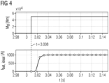
- FIG 4 shows with reference to FIG 3 a comparison of the driver's specified torque M tf with a desired ideal battery current I bat,ideal .
- an ideal, desired current is then delivered from the battery BAT in the form of the ideal battery current I bat,ideal , after a time delay.
- the desired course of the ideal battery current I bat,ideal is linear and does not exhibit any oscillations.
- I bat ,ideal z 850 z / z 2 ⁇ 1.15 z + 0 ,15
- FIG 5 shows a signal flow graph of the control system of the battery drive system from FIG 3 .
- the torque setpoint M soll is formed from the pre-control torque M ff and the driver's specified torque M tf , which is passed on to the asynchronous motor torque controller M asm controller as an input signal.
- the asynchronous motor torque controller M asm controller controls the torque of the asynchronous motor ASM via the DC/AC converter DCACW. This results in the motor current I mot .
- the motor current I mot reaches a first input of a first difference forming unit DIF1.
- the intermediate circuit direct current I dcdc reaches a second input of the first difference forming unit DIF1.
- the differential current I d is fed as an input signal to the intermediate circuit voltage regulator U zk -regulator and is converted into the differential actual voltage U d, act.
- the actual difference voltage U d, actual reaches a first input of a second difference forming unit DIF2.
- the difference actual voltage U d,ist is supplied as an input signal to a setpoint generator SWB, which specifies the difference target voltage U d, soll based on the difference actual voltage U d, ist.
- the differential target voltage U d,target is applied as an output signal of the target value generator SWB to a second input of the second difference forming unit DIF2.
- an associated intermediate circuit battery target current I bat,soll,zk is determined.
- the intermediate circuit battery target current I bat,soll,zk is supplied as an input signal to the battery current regulator I bat -controller, which uses this signal to specify both the actual battery current I bat,ist and the intermediate circuit direct current I dcdc .
- M ff z H sys ⁇ 1 z I bat ,ideal z / z
- the transfer function H sys (z) of a typical system modeling of FIG 3 is not minimal phase, so it is not stably invertible. This can be seen from the fact that a zero znmp exists outside the unit circle.
- This zero point znmp lies outside the unit circle, so that oscillations are to be expected in the battery current, while the feedforward torque should increase beyond all limits.
- FIG 6 shows with reference to FIG 3 to FIG 5 a comparison of the driver's specified torque M tf , the pre-control torque M ff and the course of a battery current I bat from practice.
- the driver requests or releases the specified torque M tf .
- the representation of the battery current I bat shows a desired (ideal) battery target current I bat,target , whose course is linear and oscillation-free.
- the battery current I bat represents a real, practical battery current I bat, practice has shown that the course is linear but subject to oscillations.
- the first output variable of the intermediate circuit voltage regulator is supplied with the second output variable of the battery current regulator to form a preset variable for the feed-in current, whereby the actual current value of the battery current is adjusted to regulate it using the feed-in current specified on the basis of the preset variable.
- the method according to the invention is based on the fact that an unstable system part of the inverse transfer function of H sys (z) is treated in such a way that oscillations and unstable behavior in the battery current are prevented.
- pole/zero cancellation reduces or prevents oscillations.
- a zero-dependent constant is added to the z-transform of the desired ideal battery current value I bat,ideal (z).
- FIG 1 shows with reference to FIG 3 a comparison of the driver's specified torque M tf to a battery current I bat,neu , which was manipulated with the aid of the present invention in order to be taken from the battery.
- FIG 2 shows a comparison of the driver's specified torque M tf , the pre-control torque M ff and the course of a battery current I bat based on the present invention.
- the driver requests or releases the specified torque M tf .
- the representation of the battery current I bat shows a desired (ideal) battery target current I bat,target , whose course is linear and oscillation-free.
- the representation of the battery current I bat shows a battery current I bat,new formed according to the invention, the course of which is linear and free of oscillations.
- the present invention enables the generation of a torque target value M target , whereby a desired battery current is drawn from the battery depending on the power requirement by the tractor driver without violating limit specifications.
- the present invention enables the ideal adjustment of the battery current without causing overshoots or oscillations in the battery current.
- the method according to the invention is based on the fact that an unstable system part is not excited by the new target signal curve.
- M ff z H sys ⁇ 1 z I bat ,new z / z
- M ff z I bat ,ideal z ⁇ I bat ,ideal znmp / z H sys z
Landscapes
- Engineering & Computer Science (AREA)
- Power Engineering (AREA)
- Transportation (AREA)
- Mechanical Engineering (AREA)
- Life Sciences & Earth Sciences (AREA)
- Sustainable Development (AREA)
- Sustainable Energy (AREA)
- Electric Propulsion And Braking For Vehicles (AREA)
Claims (6)
- Procédé de commande d'une sortie de courant d'une batterie (BAT), dans lequel la batterie (BAT) est utilisée comme batterie de traction pour entraîner (ASM) un véhicule ferroviaire,- dans lequel un courant réel de batterie Ibat,ist est parvenu en tant que courant continu de circuit intermédiaire Idcdc à un circuit intermédiaire (ZWK) par le biais d'un convertisseur CC/CC (DCDCW),- dans lequel une tension réelle différentielle Ud,ist est appliquée au circuit intermédiaire (ZWK),- dans lequel le courant continu de circuit intermédiaire Idcdc est parvenu en tant que courant moteur Imot du circuit intermédiaire (ZWK) à un convertisseur CC/CA (DCACW), qui transforme le courant moteur Imot en un courant alternatif triphasé,- dans lequel le courant alternatif triphasé est amené à un moteur asynchrone (ASM) qui est utilisé comme entraînement du véhicule ferroviaire,- dans lequel le moteur asynchrone (ASM) et le convertisseur CC/CA (DCACW) est réglé par le biais d'un régulateur de couples (régulateur Masm),- dans lequel le régulateur de couples (régulateur Masm) est utilisé pour le réglage d'une valeur de consigne de couples Msoll par laquelle le courant de moteur Imot est réglé,- dans lequel un régulateur de tension de circuit intermédiaire (régulateur Uzk) basé sur une tension de consigne différentielle Ud,soll et basé sur une tension réelle différentielle Ud,ist détermine un courant de consigne de batterie Ibat,soll, sur la base duquel est réglé le courant continu de circuit intermédiaire Idcdc,- dans lequel le convertisseur CC/CC (DCDCW) est réglé par le biais d'un régulateur de courant de batterie (régulateur Ibat) qui règle le courant continu de circuit intermédiaire Idcdc sur la base du courant de consigne de batterie Ibat,soll et sur la base du courant réel de batterie Ibat,ist- dans lequel la valeur de consigne de couples Msoll est formée d'un couple de commande prédictive Mff et d'un couple prédéfini Mtf en respectant le rapport Mtf > max (Mff),- dans lequel le couple de commande prédictive Mff est formé sur la base du courant réel de batterie Ibat,ist jusqu'à ce que le courant réel de batterie Ibat,ist corresponde à un courant idéal de batterie Ibat,idéal,- dans lequel le calcul du couple de commande prédictive Mff se fait à l'aide d'une fonction de transfert Hsys (z), qui reproduit comme suit la valeur de consigne de couples Msoll sur le courant réel de batterie Ibat,ist :caractérisé en ce
 - qu'un point zéro z=znmp qui se trouve à l'extérieur du cercle d'unité est déterminé par la fonction de transfert Hsys (z)- que le calcul du couple de commande prédictive Mff est effectué comme suit :


- Procédé selon la revendication 1, dans lequel un convertisseur est utilisé comme convertisseur CC/CA (DCACW).
- Procédé selon la revendication 1, dans lequel la tension réelle (Ud,ist) du circuit intermédiaire (ZWK) est appliquée à un condensateur.
- Procédé selon la revendication 1, dans lequel le couple de commande prédictive (Mtf) est demandé resp. libéré par un conducteur de train.
- Procédé selon la revendication 1, dans lequel le courant idéal de batterie (Ibat,idéal) est fixé resp. défini de sorte que des courants maximaux de batterie ne sont pas dépassés lors des opérations de conduite du véhicule ferroviaire.
- Procédé selon la revendication 1, dans lequel le courant idéal de batterie (Ibat,idéal) est fixé resp. défini de sorte qu'une mise en place rapide d'un couple de traction requis du moteur asynchrone (ASM) est rendue possible.
Applications Claiming Priority (2)
| Application Number | Priority Date | Filing Date | Title |
|---|---|---|---|
| DE102019219677 | 2019-12-16 | ||
| PCT/EP2020/083407 WO2021121890A1 (fr) | 2019-12-16 | 2020-11-25 | Procédé de commande de la sortie de courant d'une batterie |
Publications (2)
| Publication Number | Publication Date |
|---|---|
| EP4042556A1 EP4042556A1 (fr) | 2022-08-17 |
| EP4042556B1 true EP4042556B1 (fr) | 2024-10-09 |
Family
ID=73834447
Family Applications (1)
| Application Number | Title | Priority Date | Filing Date |
|---|---|---|---|
| EP20824099.4A Active EP4042556B1 (fr) | 2019-12-16 | 2020-11-25 | Procédé de commande de la sortie de courant d'une batterie |
Country Status (6)
| Country | Link |
|---|---|
| US (1) | US12034328B2 (fr) |
| EP (1) | EP4042556B1 (fr) |
| CN (1) | CN114788160B (fr) |
| ES (1) | ES2997986T3 (fr) |
| PL (1) | PL4042556T3 (fr) |
| WO (1) | WO2021121890A1 (fr) |
Family Cites Families (9)
| Publication number | Priority date | Publication date | Assignee | Title |
|---|---|---|---|---|
| JPH0670751B2 (ja) * | 1987-08-24 | 1994-09-07 | 日本電気株式会社 | 位相特性の推定を伴う極零分析装置 |
| US5350989A (en) * | 1993-05-13 | 1994-09-27 | Hughes Aircraft Company | Torque oscillation compensation utilizing battery current sensing |
| CN1711736A (zh) * | 2002-10-08 | 2005-12-21 | M/A-Com公司 | 用于调制信号的预加重滤波的装置、方法和产品 |
| JP5209922B2 (ja) | 2007-09-14 | 2013-06-12 | 川崎重工業株式会社 | 電気鉄道システム |
| DE102013200019B4 (de) * | 2013-01-02 | 2021-09-30 | Bombardier Transportation Gmbh | Versorgung von elektrischen Traktionsmotoren eines Schienenfahrzeugs mit elektrischer Energie unter Verwendung einer Mehrzahl von Verbrennungsmotoren |
| JP2016113111A (ja) * | 2014-12-17 | 2016-06-23 | 日立オートモティブシステムズステアリング株式会社 | 電動パワーステアリング装置及び車両搭載機器の制御装置 |
| US10017071B2 (en) * | 2016-10-13 | 2018-07-10 | GM Global Technology Operations LLC | Method and system for diagnosing contactor health in a high-voltage electrical system |
| CN107379983B (zh) | 2017-06-27 | 2019-07-16 | 中车青岛四方机车车辆股份有限公司 | 一种用于列车的蓄电池牵引供电系统及列车 |
| DE102018203015B3 (de) * | 2018-02-28 | 2019-05-09 | Siemens Aktiengesellschaft | Verfahren zur Regelung eines Batteriestroms einer Traktionsbatterie |
-
2020
- 2020-11-25 WO PCT/EP2020/083407 patent/WO2021121890A1/fr not_active Ceased
- 2020-11-25 ES ES20824099T patent/ES2997986T3/es active Active
- 2020-11-25 CN CN202080087244.1A patent/CN114788160B/zh active Active
- 2020-11-25 EP EP20824099.4A patent/EP4042556B1/fr active Active
- 2020-11-25 PL PL20824099.4T patent/PL4042556T3/pl unknown
- 2020-11-25 US US17/786,034 patent/US12034328B2/en active Active
Also Published As
| Publication number | Publication date |
|---|---|
| CN114788160B (zh) | 2025-10-10 |
| CN114788160A (zh) | 2022-07-22 |
| US12034328B2 (en) | 2024-07-09 |
| EP4042556A1 (fr) | 2022-08-17 |
| US20230045807A1 (en) | 2023-02-16 |
| PL4042556T3 (pl) | 2025-02-17 |
| ES2997986T3 (en) | 2025-02-18 |
| WO2021121890A1 (fr) | 2021-06-24 |
Similar Documents
| Publication | Publication Date | Title |
|---|---|---|
| DE102007012350B4 (de) | Verfahren und Vorrichtung zur PWM-Steuerung eines Spannungszwischenkreisumrichters | |
| EP1305876B1 (fr) | Procede pour reguler une machine electrique au moyen d'un onduleur pulse | |
| EP2433356B1 (fr) | Limitation de courant de surcharge lors du réglage de moteurs à courant triphasé alimentés par un convertisseur | |
| EP0800265A2 (fr) | Procédé et appareil pour la régulation directe de couple d'une machine à champs tournant | |
| EP0840441A1 (fr) | Régulation à orientation de champ en limite de tension pour une machine à champ tournant | |
| DE102015223365A1 (de) | Verfahren zur Ermittlung eines d- und q-Stromes zur Ansteuerung einer permanenterregten Synchronmaschine | |
| DE102012205371A1 (de) | Reglerstruktur und Verfahren zur feldorientierten Regelung einer Drehfeldmaschine bei Feldschwächung | |
| EP3763026B1 (fr) | Procédé d'opération d'un système d'entrainement électrique avec accumulateur d'énergie et dispositif pour réaliser ce procédé | |
| DE4129539A1 (de) | Verfahren und vorrichtung zur regelung der drehzahl eines elektromotors | |
| DE102004013243A1 (de) | Verfahren und Vorrichtung zur Wirkungsgradverbesserung parallelgeschalteter Gleichspannungswandler | |
| EP4042556B1 (fr) | Procédé de commande de la sortie de courant d'une batterie | |
| EP0179219A2 (fr) | Méthode et appareil pour produire une tension temporisée de commande de position | |
| DE102005060859B4 (de) | Verfahren und Vorrichtung zur Ansteuerung eines Elektromotors | |
| EP4005086B1 (fr) | Dispositif de commande, onduleur, ensemble comprenant un onduleur et une machine électrique, procédé de fonctionnement d'un onduleur et programme informatique | |
| DE102016003738A1 (de) | Zwischenkreisspannungsabhängige Rückspeiseenergiebegrenzung für elektrische Antriebe | |
| EP1880096B1 (fr) | Procede et dispositif de commande electrique d'une soupape au moyen d'un element de fermeture mecanique | |
| WO2025083083A1 (fr) | Procédé de fonctionnement d'un moteur électrique sans balai, dispositif électronique de commande en boucle fermée et/ou en boucle ouverte et outil électrique | |
| DE102022117139B4 (de) | Verfahren zum Betrieb eines Leistungswandlers | |
| DE69820262T2 (de) | Verfahren und vorrichtung zur steuerung der schalter in einem steuersystem mit variabeler struktur und steuerbarer frequenz | |
| DE102021206419B3 (de) | Regeleinrichtung zur Regelung einer eine Brennkraftmaschine und einen mit der Brennkraftmaschine antriebswirkverbundenen Generator umfassenden Leistungsanordnung, Regelanordnung mit einer solchen Regeleinrichtung, Leistungsanordnung und Verfahren zur Regelung einer Leistungsanordnung | |
| DE3223786C2 (fr) | ||
| EP3741022B1 (fr) | Procédé et dispositif de régulation d'une tension électrique | |
| WO2022128508A1 (fr) | Procédé et appareil de commande d'un onduleur | |
| DE102019218553A1 (de) | Verfahren und Vorrichtung zur Regelung einer elektrischen Maschine | |
| EP1487095A1 (fr) | Procédé et dispositif pour freiner un moteur asynchrone à vitesse variable |
Legal Events
| Date | Code | Title | Description |
|---|---|---|---|
| STAA | Information on the status of an ep patent application or granted ep patent |
Free format text: STATUS: UNKNOWN |
|
| STAA | Information on the status of an ep patent application or granted ep patent |
Free format text: STATUS: THE INTERNATIONAL PUBLICATION HAS BEEN MADE |
|
| PUAI | Public reference made under article 153(3) epc to a published international application that has entered the european phase |
Free format text: ORIGINAL CODE: 0009012 |
|
| STAA | Information on the status of an ep patent application or granted ep patent |
Free format text: STATUS: REQUEST FOR EXAMINATION WAS MADE |
|
| 17P | Request for examination filed |
Effective date: 20220512 |
|
| AK | Designated contracting states |
Kind code of ref document: A1 Designated state(s): AL AT BE BG CH CY CZ DE DK EE ES FI FR GB GR HR HU IE IS IT LI LT LU LV MC MK MT NL NO PL PT RO RS SE SI SK SM TR |
|
| DAV | Request for validation of the european patent (deleted) | ||
| DAX | Request for extension of the european patent (deleted) | ||
| REG | Reference to a national code |
Ref country code: DE Ref legal event code: R079 Free format text: PREVIOUS MAIN CLASS: H02P0001260000 Ipc: B60L0015020000 Ref document number: 502020009469 Country of ref document: DE |
|
| GRAP | Despatch of communication of intention to grant a patent |
Free format text: ORIGINAL CODE: EPIDOSNIGR1 |
|
| STAA | Information on the status of an ep patent application or granted ep patent |
Free format text: STATUS: GRANT OF PATENT IS INTENDED |
|
| RIC1 | Information provided on ipc code assigned before grant |
Ipc: H02P 1/26 20060101ALI20240516BHEP Ipc: H02J 7/00 20060101ALI20240516BHEP Ipc: B60L 50/60 20190101ALI20240516BHEP Ipc: B60L 15/20 20060101ALI20240516BHEP Ipc: B60L 15/02 20060101AFI20240516BHEP |
|
| INTG | Intention to grant announced |
Effective date: 20240607 |
|
| GRAS | Grant fee paid |
Free format text: ORIGINAL CODE: EPIDOSNIGR3 |
|
| GRAA | (expected) grant |
Free format text: ORIGINAL CODE: 0009210 |
|
| STAA | Information on the status of an ep patent application or granted ep patent |
Free format text: STATUS: THE PATENT HAS BEEN GRANTED |
|
| AK | Designated contracting states |
Kind code of ref document: B1 Designated state(s): AL AT BE BG CH CY CZ DE DK EE ES FI FR GB GR HR HU IE IS IT LI LT LU LV MC MK MT NL NO PL PT RO RS SE SI SK SM TR |
|
| REG | Reference to a national code |
Ref country code: CH Ref legal event code: EP |
|
| REG | Reference to a national code |
Ref country code: DE Ref legal event code: R096 Ref document number: 502020009469 Country of ref document: DE |
|
| REG | Reference to a national code |
Ref country code: IE Ref legal event code: FG4D Free format text: LANGUAGE OF EP DOCUMENT: GERMAN |
|
| REG | Reference to a national code |
Ref country code: LT Ref legal event code: MG9D |
|
| REG | Reference to a national code |
Ref country code: ES Ref legal event code: FG2A Ref document number: 2997986 Country of ref document: ES Kind code of ref document: T3 Effective date: 20250218 |
|
| PG25 | Lapsed in a contracting state [announced via postgrant information from national office to epo] |
Ref country code: NL Free format text: LAPSE BECAUSE OF FAILURE TO SUBMIT A TRANSLATION OF THE DESCRIPTION OR TO PAY THE FEE WITHIN THE PRESCRIBED TIME-LIMIT Effective date: 20241009 |
|
| PG25 | Lapsed in a contracting state [announced via postgrant information from national office to epo] |
Ref country code: NL Free format text: LAPSE BECAUSE OF FAILURE TO SUBMIT A TRANSLATION OF THE DESCRIPTION OR TO PAY THE FEE WITHIN THE PRESCRIBED TIME-LIMIT Effective date: 20241009 |
|
| PG25 | Lapsed in a contracting state [announced via postgrant information from national office to epo] |
Ref country code: PT Free format text: LAPSE BECAUSE OF FAILURE TO SUBMIT A TRANSLATION OF THE DESCRIPTION OR TO PAY THE FEE WITHIN THE PRESCRIBED TIME-LIMIT Effective date: 20250210 Ref country code: IS Free format text: LAPSE BECAUSE OF FAILURE TO SUBMIT A TRANSLATION OF THE DESCRIPTION OR TO PAY THE FEE WITHIN THE PRESCRIBED TIME-LIMIT Effective date: 20250209 Ref country code: HR Free format text: LAPSE BECAUSE OF FAILURE TO SUBMIT A TRANSLATION OF THE DESCRIPTION OR TO PAY THE FEE WITHIN THE PRESCRIBED TIME-LIMIT Effective date: 20241009 |
|
| PG25 | Lapsed in a contracting state [announced via postgrant information from national office to epo] |
Ref country code: FI Free format text: LAPSE BECAUSE OF FAILURE TO SUBMIT A TRANSLATION OF THE DESCRIPTION OR TO PAY THE FEE WITHIN THE PRESCRIBED TIME-LIMIT Effective date: 20241009 |
|
| PG25 | Lapsed in a contracting state [announced via postgrant information from national office to epo] |
Ref country code: BG Free format text: LAPSE BECAUSE OF FAILURE TO SUBMIT A TRANSLATION OF THE DESCRIPTION OR TO PAY THE FEE WITHIN THE PRESCRIBED TIME-LIMIT Effective date: 20241009 |
|
| PG25 | Lapsed in a contracting state [announced via postgrant information from national office to epo] |
Ref country code: NO Free format text: LAPSE BECAUSE OF FAILURE TO SUBMIT A TRANSLATION OF THE DESCRIPTION OR TO PAY THE FEE WITHIN THE PRESCRIBED TIME-LIMIT Effective date: 20250109 |
|
| PG25 | Lapsed in a contracting state [announced via postgrant information from national office to epo] |
Ref country code: LV Free format text: LAPSE BECAUSE OF FAILURE TO SUBMIT A TRANSLATION OF THE DESCRIPTION OR TO PAY THE FEE WITHIN THE PRESCRIBED TIME-LIMIT Effective date: 20241009 Ref country code: GR Free format text: LAPSE BECAUSE OF FAILURE TO SUBMIT A TRANSLATION OF THE DESCRIPTION OR TO PAY THE FEE WITHIN THE PRESCRIBED TIME-LIMIT Effective date: 20250110 |
|
| PGFP | Annual fee paid to national office [announced via postgrant information from national office to epo] |
Ref country code: CH Payment date: 20250210 Year of fee payment: 5 |
|
| PG25 | Lapsed in a contracting state [announced via postgrant information from national office to epo] |
Ref country code: RS Free format text: LAPSE BECAUSE OF FAILURE TO SUBMIT A TRANSLATION OF THE DESCRIPTION OR TO PAY THE FEE WITHIN THE PRESCRIBED TIME-LIMIT Effective date: 20250109 |
|
| PG25 | Lapsed in a contracting state [announced via postgrant information from national office to epo] |
Ref country code: SM Free format text: LAPSE BECAUSE OF FAILURE TO SUBMIT A TRANSLATION OF THE DESCRIPTION OR TO PAY THE FEE WITHIN THE PRESCRIBED TIME-LIMIT Effective date: 20241009 |
|
| PG25 | Lapsed in a contracting state [announced via postgrant information from national office to epo] |
Ref country code: MC Free format text: LAPSE BECAUSE OF FAILURE TO SUBMIT A TRANSLATION OF THE DESCRIPTION OR TO PAY THE FEE WITHIN THE PRESCRIBED TIME-LIMIT Effective date: 20241009 |
|
| PG25 | Lapsed in a contracting state [announced via postgrant information from national office to epo] |
Ref country code: DK Free format text: LAPSE BECAUSE OF FAILURE TO SUBMIT A TRANSLATION OF THE DESCRIPTION OR TO PAY THE FEE WITHIN THE PRESCRIBED TIME-LIMIT Effective date: 20241009 |
|
| REG | Reference to a national code |
Ref country code: DE Ref legal event code: R097 Ref document number: 502020009469 Country of ref document: DE |
|
| PG25 | Lapsed in a contracting state [announced via postgrant information from national office to epo] |
Ref country code: LU Free format text: LAPSE BECAUSE OF NON-PAYMENT OF DUE FEES Effective date: 20241125 |
|
| PG25 | Lapsed in a contracting state [announced via postgrant information from national office to epo] |
Ref country code: EE Free format text: LAPSE BECAUSE OF FAILURE TO SUBMIT A TRANSLATION OF THE DESCRIPTION OR TO PAY THE FEE WITHIN THE PRESCRIBED TIME-LIMIT Effective date: 20241009 |
|
| PG25 | Lapsed in a contracting state [announced via postgrant information from national office to epo] |
Ref country code: RO Free format text: LAPSE BECAUSE OF FAILURE TO SUBMIT A TRANSLATION OF THE DESCRIPTION OR TO PAY THE FEE WITHIN THE PRESCRIBED TIME-LIMIT Effective date: 20241009 |
|
| PG25 | Lapsed in a contracting state [announced via postgrant information from national office to epo] |
Ref country code: SK Free format text: LAPSE BECAUSE OF FAILURE TO SUBMIT A TRANSLATION OF THE DESCRIPTION OR TO PAY THE FEE WITHIN THE PRESCRIBED TIME-LIMIT Effective date: 20241009 |
|
| PLBE | No opposition filed within time limit |
Free format text: ORIGINAL CODE: 0009261 |
|
| STAA | Information on the status of an ep patent application or granted ep patent |
Free format text: STATUS: NO OPPOSITION FILED WITHIN TIME LIMIT |
|
| REG | Reference to a national code |
Ref country code: DE Ref legal event code: R081 Ref document number: 502020009469 Country of ref document: DE Owner name: SIEMENS MOBILITY GMBH, DE Free format text: FORMER OWNER: SIEMENS MOBILITY GMBH, 81739 MUENCHEN, DE |
|
| REG | Reference to a national code |
Ref country code: BE Ref legal event code: MM Effective date: 20241130 |
|
| PG25 | Lapsed in a contracting state [announced via postgrant information from national office to epo] |
Ref country code: SE Free format text: LAPSE BECAUSE OF FAILURE TO SUBMIT A TRANSLATION OF THE DESCRIPTION OR TO PAY THE FEE WITHIN THE PRESCRIBED TIME-LIMIT Effective date: 20241009 |
|
| 26N | No opposition filed |
Effective date: 20250710 |
|
| GBPC | Gb: european patent ceased through non-payment of renewal fee |
Effective date: 20250109 |
|
| PG25 | Lapsed in a contracting state [announced via postgrant information from national office to epo] |
Ref country code: BE Free format text: LAPSE BECAUSE OF NON-PAYMENT OF DUE FEES Effective date: 20241130 Ref country code: GB Free format text: LAPSE BECAUSE OF NON-PAYMENT OF DUE FEES Effective date: 20250109 |
|
| PG25 | Lapsed in a contracting state [announced via postgrant information from national office to epo] |
Ref country code: IE Free format text: LAPSE BECAUSE OF NON-PAYMENT OF DUE FEES Effective date: 20241125 |
|
| PGFP | Annual fee paid to national office [announced via postgrant information from national office to epo] |
Ref country code: AT Payment date: 20251014 Year of fee payment: 6 |
|
| PGFP | Annual fee paid to national office [announced via postgrant information from national office to epo] |
Ref country code: IT Payment date: 20251125 Year of fee payment: 6 |
|
| PGFP | Annual fee paid to national office [announced via postgrant information from national office to epo] |
Ref country code: FR Payment date: 20251114 Year of fee payment: 6 |
|
| PGFP | Annual fee paid to national office [announced via postgrant information from national office to epo] |
Ref country code: CZ Payment date: 20251119 Year of fee payment: 6 |
|
| PGFP | Annual fee paid to national office [announced via postgrant information from national office to epo] |
Ref country code: PL Payment date: 20251114 Year of fee payment: 6 |
|
| REG | Reference to a national code |
Ref country code: CH Ref legal event code: U11 Free format text: ST27 STATUS EVENT CODE: U-0-0-U10-U11 (AS PROVIDED BY THE NATIONAL OFFICE) Effective date: 20260209 |
|
| PG25 | Lapsed in a contracting state [announced via postgrant information from national office to epo] |
Ref country code: HU Free format text: LAPSE BECAUSE OF FAILURE TO SUBMIT A TRANSLATION OF THE DESCRIPTION OR TO PAY THE FEE WITHIN THE PRESCRIBED TIME-LIMIT; INVALID AB INITIO Effective date: 20201125 |
|
| PG25 | Lapsed in a contracting state [announced via postgrant information from national office to epo] |
Ref country code: CY Free format text: LAPSE BECAUSE OF FAILURE TO SUBMIT A TRANSLATION OF THE DESCRIPTION OR TO PAY THE FEE WITHIN THE PRESCRIBED TIME-LIMIT; INVALID AB INITIO Effective date: 20201125 |
|
| PGFP | Annual fee paid to national office [announced via postgrant information from national office to epo] |
Ref country code: ES Payment date: 20260220 Year of fee payment: 6 |
|
| PGFP | Annual fee paid to national office [announced via postgrant information from national office to epo] |
Ref country code: DE Payment date: 20260119 Year of fee payment: 6 |