EP4042756B1 - Verbesserung des durchschnittlichen eirp-regelintervalls durch zeitausgeblendete planung - Google Patents
Verbesserung des durchschnittlichen eirp-regelintervalls durch zeitausgeblendete planung Download PDFInfo
- Publication number
- EP4042756B1 EP4042756B1 EP19790078.0A EP19790078A EP4042756B1 EP 4042756 B1 EP4042756 B1 EP 4042756B1 EP 19790078 A EP19790078 A EP 19790078A EP 4042756 B1 EP4042756 B1 EP 4042756B1
- Authority
- EP
- European Patent Office
- Prior art keywords
- prbs
- limit
- future
- scheduled
- slots
- Prior art date
- Legal status (The legal status is an assumption and is not a legal conclusion. Google has not performed a legal analysis and makes no representation as to the accuracy of the status listed.)
- Active
Links
Images




Classifications
-
- H—ELECTRICITY
- H04—ELECTRIC COMMUNICATION TECHNIQUE
- H04W—WIRELESS COMMUNICATION NETWORKS
- H04W52/00—Power management, e.g. Transmission Power Control [TPC] or power classes
- H04W52/04—Transmission power control [TPC]
- H04W52/30—Transmission power control [TPC] using constraints in the total amount of available transmission power
- H04W52/36—Transmission power control [TPC] using constraints in the total amount of available transmission power with a discrete range or set of values, e.g. step size, ramping or offsets
- H04W52/367—Power values between minimum and maximum limits, e.g. dynamic range
-
- H—ELECTRICITY
- H04—ELECTRIC COMMUNICATION TECHNIQUE
- H04W—WIRELESS COMMUNICATION NETWORKS
- H04W52/00—Power management, e.g. Transmission Power Control [TPC] or power classes
- H04W52/04—Transmission power control [TPC]
- H04W52/06—TPC algorithms
- H04W52/14—Separate analysis of uplink or downlink
- H04W52/143—Downlink power control
-
- H—ELECTRICITY
- H04—ELECTRIC COMMUNICATION TECHNIQUE
- H04W—WIRELESS COMMUNICATION NETWORKS
- H04W72/00—Local resource management
- H04W72/04—Wireless resource allocation
- H04W72/044—Wireless resource allocation based on the type of the allocated resource
- H04W72/0446—Resources in time domain, e.g. slots or frames
-
- H—ELECTRICITY
- H04—ELECTRIC COMMUNICATION TECHNIQUE
- H04W—WIRELESS COMMUNICATION NETWORKS
- H04W72/00—Local resource management
- H04W72/12—Wireless traffic scheduling
- H04W72/1263—Mapping of traffic onto schedule, e.g. scheduled allocation or multiplexing of flows
- H04W72/1273—Mapping of traffic onto schedule, e.g. scheduled allocation or multiplexing of flows of downlink data flows
Definitions
- the present disclosure relates to wireless communication, and particularly relate to methods, apparatus and computer programs for controlling the output of a transmission point.
- RF exposure regulations need to be accounted for. These exposure limitations are typically based on the guidelines from the International Commission on Non-Ionizing Radiation Protection (ICNIRP) but may take different forms in different countries and regions.
- ICNIRP International Commission on Non-Ionizing Radiation Protection
- the aim of the RF exposure regulations is to ensure that human exposure to RF energy is kept within safe limits, which have typically been set with wide safety margins.
- AAS advanced antenna systems
- MIMO multiple-input-multiple-output
- mmW millimeter - wave
- the RF exposure limits are typically expressed in terms of power density (W/m 2 ) which in the far field is proportional to the effective isotropic radiated power (EIRP), i.e. the power radiated from an antenna with unity antenna gain in all directions. Consequently, the EIRP can be used to determine the power density in the far field. This implies that at a given distance from the antenna, and in the far field, the experienced momentary EIRP and power density will be higher in a beam generated by an AAS system with beam forming gain, than without such an AAS system.
- EIRP effective isotropic radiated power
- the ICNIRP and other RF exposure limitations are usually expressed as an average power density over a specified time interval T. This means that the momentary or instantaneous power density can be higher than the specified limit, but the average power density must be below the limit. It will further be understood that the power density varies inversely with distance from the transmitter. The distance from the transmitter at which the specified limit is met is referred to as the "compliance distance". To maintain a certain RF exposure compliance distance, which is shorter than that obtained using the maximum momentary EIRP of the AAS, the time-averaged power needs to be maintained at or below a pre-determined threshold.
- US 8 811 213 B1 discloses a system for scheduling physical resource blocks.
- Base stations, of a communication radio access network may be configured with schedulers that assign one or more physical resource blocks to a communication channel of a wireless device based on distance or power.
- the physical resource blocks allow the wireless device to communicate with the base station.
- Some resource blocks may be monitored across multiple sites to determine whether an aggregate power for the resource blocks exceeds a threshold. When the aggregate power threshold is surpassed, the schedulers may limit or prevent use of the identified resource blocks.
- WO 2013/169151 A1 discloses a method in a radio base station for controlling transmit power in a wireless communication system. The method comprises determining a first transmit power of at least a first type of subframe which is higher than a maximum allowed average output power of the radio base station, and a second transmit power of at least a second type of subframe which is lower than the maximum allowed average output power. An average transmit power by which the radio base station transmitted an amount of subframes during a preceding time period is determined. Moreover, a maximum allowed power for subsequent subframe based on the determined average transmit power and the maximum allowed average output power is determined. Finally, at least one type of subframe to be allowed for the subsequent subframe based on the determined maximum allowed power for the subsequent subframe and at least the first and second transmit power is determined.
- EP 3 518 587 A1 discloses a method for modifying an electromagnetic field distribution of a node in a telecommunication network, comprising determining the presence of an entity within a region of interest, and regulating transmission power to the region of interest from the node by varying a spatiotemporal transmission profile of the node in response to determining the presence of the entity in the region for a period of time longer than a predetermined threshold value, wherein modifying the electromagnetic field distribution of the node comprises modifying an average electromagnetic field distribution of said node.
- WO 2016/034244 A1 discloses a base station controller for controlling the radio frequency emission of at least one antenna of a base station of a wireless communication system, comprising an obtaining unit configured to obtain a current emission value of the radio frequency emission of the at least one antenna, and a control unit configured to control the radio frequency emission of the at least one antenna on the basis of the obtained current emission value.
- An aspect of the present invention provides a method in a network node for controlling a radio transmitter.
- the control window comprises a plurality of control steps, and each control step comprises a plurality of slots.
- the determined first limit is less than or equal to a pre-configured second limit representing a number of PRBs that can be scheduled in a single slot
- the first limit is a respective first fraction of a total number of PRBs of the wireless network
- the second limit is a respective second fraction of a total number of PRBs of the wireless network.
- the step of determining the first limit comprises:
- the predetermined average output power reference value is ( ⁇ P max,sire - e), where ⁇ is a predetermined relative limit and e is a predetermined margin, and wherein determining the maximum number of PRBs that can be scheduled comprises setting the maximum number of PRBs that can be scheduled in the ith future control step to a hard limit value corresponding to the predetermined output power reference value, when the allowable average output power of the radio transmitter in the ith future control step is greater than the predetermined average output power reference value.
- a lower limit of PRBs that can be scheduled in a single slot is an integer multiple of a frequency-domain scheduling granularity.
- the frequency-domain scheduling granularity may be equal to at least two PRBs. In some specific embodiments the frequency-domain scheduling granularity is equal to eight PRBs.
- scheduling PRBs in the proportion of the plurality of consecutive future slots comprises:
- Embodiments of a base station, communication system, and a method in a communication system are also disclosed.
- Radio Node As used herein, a "radio node” is either a radio access node or a wireless device.
- Radio Access Node As used herein, a "radio access node” or “radio network node” is any node in a radio access network of a cellular communications network that operates to wirelessly transmit and/or receive signals.
- a radio access node include, but are not limited to, a base station (e.g., a New Radio (NR) base station (gNB) in a Third Generation Partnership Project (3GPP) Fifth Generation (5G) NR network or an enhanced or evolved Node B (eNB) in a 3GPP Long Term Evolution (LTE) network), a high-power or macro base station, a low-power base station (e.g., a micro base station, a pico base station, a home eNB, or the like), and a relay node.
- a base station e.g., a New Radio (NR) base station (gNB) in a Third Generation Partnership Project (3GPP) Fifth Generation (5G) NR network or an enhanced or evolved Node B (eNB) in a
- a "core network node” is any type of node in a core network.
- Some examples of a core network node include, e.g., a Mobility Management Entity (MME), a Packet Data Network Gateway (P-GW), a Service Capability Exposure Function (SCEF), or the like.
- MME Mobility Management Entity
- P-GW Packet Data Network Gateway
- SCEF Service Capability Exposure Function
- a "wireless device” is any type of device that has access to (i.e., is served by) a cellular communications network by wirelessly transmitting (and/or receiving) signals to (and/or from) a radio access node.
- a wireless device include, but are not limited to, a User Equipment device (UE) in a 3GPP network and a Machine Type Communication (MTC) device.
- UE User Equipment device
- MTC Machine Type Communication
- Network Node As used herein, a "network node” is any node that is either part of the radio access network or the core network of a cellular communications network/system.
- a "cell” is a combination of radio resources (such as, for example, antenna port allocation, time and frequency) that a wireless device may use to exchange radio signals with a radio access node, which may be referred to as a host node or a serving node of the cell.
- a radio access node which may be referred to as a host node or a serving node of the cell.
- beams may be used instead of cells, particularly with respect to 5G NR. As such, it should be appreciated that the techniques described herein are equally applicable to both cells and beams.
- references in this disclosure to various technical standards should be understood to refer to the specific version(s) of such standard(s) that was(were) current at the time the present application was filed, and may also refer to applicable counterparts and successors of such versions, as applicable.
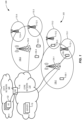
- FIG. 1 illustrates one example of a cellular communications network 100 in which embodiments of the present disclosure may be implemented.
- the cellular communications network 100 is a Public Land Mobility Network (PLMN) conforming to one or more of the LTE, 3G, 4G and 5G NR standards, or their successors.
- PLMN Public Land Mobility Network
- the cellular communications network 100 includes a (Radio) Access Network ((R)AN) 102 comprising base stations 104-1 and 104-2 controlling radio communications with wireless devices 106-1, 106-2, 106-3, 106-4,106-5 within corresponding macro cells 108-1 and 108-2.
- R Radio Access Network
- Each macro cell 108 may be defined by any suitable combination of geography, frequency, Radio Access Technology (RAT) and modulation scheme.
- RAT Radio Access Technology
- Base stations 104 can be any type of network access device capable of establishing radio connection(s) with one or more wireless devices 106 within a respective coverage area of the base station 104 or low power node 112, and further configured to forward subscriber traffic between the core network 114 and the one or more wireless devices 106.
- An important feature of a base station 104 is that it is configured with both a radio interface configured to send and receive radio signals to and from a wireless device 106, and a network interface configured to exchange electronic and/or optical signals with the core network 114.
- Examples of base stations 104 and low power nodes 112 include: Evolved Node B (eNB) systems (known, for example, in the 3GPP standards): Wireless Local Area Network (WLAN) access points (known, for example from IEEE 802.11 standards) or the like.
- eNB Evolved Node B
- WLAN Wireless Local Area Network
- a base station 104 may be referred to as an access point (AP) regardless of the Radio Access Technology (RAT) that it supports.
- AP access point
- RAT Radio Access Technology
- base stations 104 and low power nodes 112 may be generically referred to a radio transmitters or transmission points.
- the illustrated (R)AN 102 also includes small cells 110-1 through 110-4, within which radio communication can be controlled by corresponding low power nodes 112-1 through 112-4.
- each small cell may be defined by any suitable combination of geography, frequency, Radio Access Technology (RAT) and modulation scheme.
- RAT Radio Access Technology
- a low power node 112 can be any type of network access device capable of establishing radio connection(s) with one or more wireless devices 106 within a respective coverage area of the low power node 112, and further configured to forward subscriber traffic between the core network 114 and the one or more wireless devices 106.
- a low power node 112 is configured with both a radio interface configured to send and receive radio signals to and from a wireless device 106, and a network interface configured to exchange electronic and/or optical signals with the core network 114.
- a low power node 112 may be connected to the core network 114 by a direct connection, such as an optical cable.
- a low power node 112 may be connected to the core network 114 by an indirect connection, such as via a radio or optical fiber link to a base station 104. Examples of low power nodes 112 include: Remote Radio Heads (RRHs) connected to a base station or a network router (not shown): WLAN access points or the like.
- RRHs Remote Radio Heads
- a low power node 112 may be referred to as an access point (AP) regardless of the specific Radio Access Technology (RAT) that it supports.
- AP access point
- RAT Radio Access Technology
- a particular small cell 110 may alternatively be controlled by a base station 104, for example using a beam-forming technique.
- the particular small cell 110 will not be associated with a respective low power node 112 per se. Rather, the particular small cell 110 will be associated with a respective set of parameters implemented in the base station 104.
- the term "cell” is used to refer to a defined combination of parameters (such as geography, frequency, Radio Access Technology (RAT), modulation scheme, identifiers and the like) that can be used by a wireless device 106 to access communication services of the network 100.
- the term "cell” does not imply any particular parameter values, or any particular physical configuration of devices needed to enable a wireless device 106 to access those communication services.
- Wireless devices 106 can be any type of device capable of sending and receiving radio signals to and from a base station 104 and/or low power node 112. Examples of wireless device 106 include cellular phones, Personal Data Assistants (PDAs), mobile computers, Internet of Things (IoT) devices, autonomous vehicle controllers, and the like. In some contexts, a wireless device 106 may be referred to as a User Equipment (UE) or a mobile device.
- PDAs Personal Data Assistants
- IoT Internet of Things
- a wireless device 106 may be referred to as a User Equipment (UE) or a mobile device.
- UE User Equipment
- the macro cells 108-1 and 108-2 may overlap each other, and may also overlap one or more small cells 110.
- a particular macro cell 108-1 may be one macro cell 108 among a plurality of macro cells covering a common geographical region and having a common RAT and modulation scheme, but using respective different frequencies and/or AP identifiers.
- a wireless device 106 located within a region covered by two or more overlapping cells 108, 112 may send and receive radio signals to and from each of the corresponding base stations 104 and/or low power nodes 112.
- the (R)AN 102 is connected to a Core Network (CN) 114, which may also be referred to as Evolved Core Network (ECN) or Evolved Packet Core (EPC).
- the CN 114 includes (or, equivalently, is connected to) one or more servers 116 configured to provide networking services such as, for example, Network Functions (NFs) described in 3GPP TS 23.501 V15.2.0 (2018-06) "System Architecture for the 5G System " and its successors.
- the CN 114 also includes one or more gateway (GW) nodes 118 configured to connect the CN 114 to a packet data network (DN) 120 such as, for example, the internet.
- DN packet data network
- a gateway node 118 may be referred to as a packet gateway (PGW) and/or a serving gateway (SGW).
- the DN 120 may provide communications services to support end-to-end communications between wireless devices 106 and one or more application servers (ASs) 122 configured to exchange data packet flows with the wireless devices 106 via the CN 114 and (R)AN 102.
- ASs application servers
- an application server (AS) 122 may also be referred to as a host server.
- an end-to-end signal path between an AS 122 and one or more wireless devices 106 may be referred to as an Over-The-Top (OTT) connection.
- OTT Over-The-Top
- a communication service that employs signal transmission between an AS 122 and one or more wireless devices 106 may be referred to as an OTT service.
- the separation between the CN 114 and the DN 120 can be purely logical, in order to simplify understanding of their respective roles.
- the CN 114 is primarily focused on providing wireless device access services and supporting wireless device mobility.
- the DN 120 is primarily focused on providing end-to-end communications, particularly across network domains.
- both the CN 114 and the DN 120 can be implemented on common physical network infrastructure, if desired.
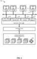
- FIGs. 2A and 2B is a block diagram schematically illustrating a communications system 200 including a computing device 202 usable in embodiments of the present invention.
- any or all of the base stations 104 or 112, wireless devices 106, core network servers 116 or gateways 118 and data network servers 122 may be implemented using systems and principles in accordance with the computing device 202.
- any or all of the elements of the network 100 may be virtualized using techniques known in the art or developed in the future, in which case the functions of any or all the base stations 104 or 112, core network servers 116 or gateways 118, and/or any or all of the network functions 206-226 may be implemented by suitable software executing within a computing device 202 or within a data center (non shown) composed of multiple computing devices 202.
- the communications system 200 generally includes computing device 202 connected to one or more networks 210 and one or more radio units 212.
- the computing device 202 includes one or more processors 204, a memory 206, one or more network interfaces 208.
- the processors 204 may be provided as any suitable combination of Central Processing Units (CPUs), Application Specific Integrated Circuits (ASICs), Field Programmable Gate Arrays (FPGAs), or the like.
- the memory 206 may be provided as any suitable combination of Random Access Memory (RAM), Read Only Memory (ROM) and mass storage technologies such as magnetic or optical disc storage or the like.
- the network interfaces 208 enable signaling between the computing device 200 and the networks 210, such as the Core Network 114, the data network 120, or a private domain network such as a data center (not shown).
- Each radio unit 212 typically includes at least one transmitter (Tx) 214 and at least one receiver (Rx) 216 coupled to one or more antennas 218.
- the radio unit(s) 212 is(are) shown as being external to the computing device 202 and connected to the computing device 202 via a suitable physical connection (such as a copper cable or an optical cable).
- the radio unit(s) 212 is(are) shown as being connected to computing device 202 via a network 210 and a network interface 208.
- the radio unit(s) 212 and optionally also the antenna(s) 218 may be integrated together with the computing device 202.
- the one or more processors 204 operate to provide functions of the computing device 202. Typically, these function(s) are implemented as software applications (APPs) 220 or modules that are stored in the memory 206, for example, and executed by the one or more processors 204. In some embodiments, one or more software applications or modules 220 may execute within a secure run-time environment (RTE) 222 maintained by an operating system (not shown) of the computing device 202.
- RTE secure run-time environment
- a computing device 202 configured to implement a wireless device 106 may incorporate one or more processors 204, a memory 206, and one or more radio units 212, but may exclude a network interface 208.
- a computing device 202 configured to implement a server 116 or 122 may include one or more processors 204, a memory 206, and one or more network interfaces 208, but may exclude radio units 212.
- a computing device 202 configured to implement a base station 104 or 112, on the other hand, will normally include one or more processors 204, a memory 206, and both radio units 212 and network interfaces 208.
- FIG. 3 is a block diagram schematically illustrating an example architecture for network element virtualization usable in embodiments of the present invention. It is contemplated that the network elements may be physically implemented using one or more computers, data storage devices and routers (any or all of which may be constructed in accordance with the system 200 described above with reference to FIG. 3 ) interconnected together and executing suitable software to perform its intended functions. Those of ordinary skill will recognize that there are many suitable combinations of hardware and software that may be used for this purpose, which are either known in the art or may be developed in the future. For this reason, a figure showing physical hardware components and connections is not included herein.
- the illustrated architecture 300 generally comprises hosting infrastructure 302, a virtualization layer 304 and an Application Platform Services layer 306.
- the hosting infrastructure 302 comprises physical hardware resources provided by the infrastructure on which the architecture 300 is being implemented. These physical hardware resources may include any or all of the processors 204, memory 206, network interfaces 208 and radio units 212 described above with reference to FIG. 2 , and may also include traffic forwarding and routing hardware 308.
- the virtualization layer 304 presents an abstraction of the hardware resources 302 to the Application Platform Services layer 306. The specific details of this abstraction will depend on the requirements of the applications 220 being hosted by the Application Platform Services layer 306.
- an APP 220 that provides traffic forwarding functions may be presented with an abstraction of the hardware resources 306 (e.g. processor(s) 204, memory 206 and traffic forwarding hardware 308) that simplifies the implementation of traffic forwarding policies.
- an application that provides data storage functions may be presented with an abstraction of the hardware resources 306 (e.g. processor(s) 204 and memory 206) that facilitates the storage and retrieval of data (for example using Lightweight Directory Access Protocol - LDAP).
- the application platform 306 provides the capabilities for hosting applications.
- the application platform 306 supports a flexible and efficient multi-tenancy run-time and hosting environment for applications 220 by providing Infrastructure as a Service (laaS) facilities.
- the application platform 306 may provide a security and resource "sandbox" for each application 220 being hosted by the platform 306.
- Each "sandbox” may be implemented as a Virtual Machine (VM) image 310 that may include an appropriate operating system and controlled access to (virtualized) hardware resources 302.
- VM Virtual Machine
- each "sandbox” may be implemented as a container 311 that may include appropriate virtual memory and controlled access to host operating system and (virtualized) hardware resources 302.
- the application platform 306 may also provide a set of middleware application services and infrastructure services to the applications 220 hosted on the application platform 306, as will be described in greater detail below.
- PCF 220 may be implemented by means of one or more applications 220 hosted on the application platform 306 as described above. Communication between applications 220 and services of the application platform 306 may conveniently be designed according to the principles of Service-Oriented Architecture (SOA) known in the art.
- SOA Service-Oriented Architecture
- Communication services 312 may allow applications 220 to communicate with the application platform 306 (through pre-defined Application Programming Interfaces (APIs) for example) and with each other (for example through a service-specific API).
- APIs Application Programming Interfaces
- a Service registry 314 may provide visibility of the services available on the server 200.
- the service registry 220 may present service availability (e.g. status of the service) together with the related interfaces and versions. This may be used by applications 214 to discover and locate the end-points for the services they require, and to publish their own service end-point for other applications to use.
- Network Information Services (NIS) 316 may provide applications 220 with low-level network information pertaining to a network service instance or one or more PDU sessions, for example.
- the information provided by NIS 316 may be used by an application 220 to calculate and present relevant data (such as: cell-ID, location of the subscriber, cell load and throughput guidance) to SMF 208, AMF 210 and PCF 220, any or all of which may themselves to implemented by applications 220 executing in respective VMs 310.
- a Traffic Off-Load Function (TOF) service 318 may prioritize traffic, and route selected, policy-based, data streams to and from applications 220.
- TOF Traffic Off-Load Function
- radio resources refers to any available resource which can be used to transmit wireless signals, such as frequency (e.g. one or more frequency channels or sub-channels), time (e.g. one or more frames, sub-frames, slots, etc) or codes (e.g. as used for code-division multiplexing).
- a pool of available radio resources is distributed for transmissions to the wireless devices 106 according to a scheduling algorithm.
- Various scheduling algorithms are known in the art, and the present disclosure is not limited in that respect. Suitable examples include round robin, fair queuing, proportionally fair scheduling and maximum throughput.
- the output power of a radio access node varies as a function of the resources it uses for transmissions. For example, when the radio access node is scheduled to transmit using a relatively large amount of resources at any one time (e.g. a relatively large number of frequencies), the output power of that radio access node will also be relatively high. Conversely, when the radio access node is scheduled to transmit using relatively few resources at any one time, the output power of that radio access node will be relatively low.
- Embodiments of the present disclosure utilize this property to control the output of a transmission point (e.g. a radio access node) of a wireless communications network.
- the output of the transmission point is controlled so that an average transmitted power requirement is met.
- the radio access node is thus provided with a pool of radio resources with which to schedule transmissions to the wireless devices 106.
- Embodiments of the disclosure apply limitations to this pool of radio resources so as to limit the output power of the radio access node or transmission point.
- the radio access node may be permitted to utilize only a fraction of its available pool of radio resources for scheduling transmissions to the wireless devices 106.
- a specific problem with some RATs that reduces the control range of an average power control system, due to the smallest scheduling granularity in the frequency domain.
- the smallest scheduling granularity is 8 physical resource blocks (PRBs). This means that when average power control is applied in some bandwidths, the average power limit cannot be set lower than about 20% of the access node power.
- PRBs physical resource blocks
- the present disclosure provides techniques that enable the lower limit of the average power control range to be reduced well below the level corresponding to the 8 PRB minimum scheduling granularity.
- an aspect of the present invention provides a method in a network node for controlling a radio transmitter.
- determining (906) a first limit representing a number of physical resource blocks, PRBs, that can be scheduled in each one of a plurality of consecutive future slots of a current control step, based at least in part on an allowable average output power of the radio transmitter.
- the control window comprises a plurality of control steps, and each control step comprises a plurality of slots.
- the determined first limit is less than or equal to a pre-configured second limit representing a number of PRBs that can be scheduled in a single slot (904)
- scheduling (906) PRBs in a proportion of the plurality of consecutive future slots of the current control step, the proportion being calculated such that an averaged fraction of scheduled PRBs in the current control step is less than or equal to the first limit.
- the first limit may be a respective first fraction of a total number of PRBs of the wireless network
- the second limit may be a respective second fraction of a total number of PRBs of the wireless network
- the step of determining the first limit comprises: calculating an allowable average output power of the radio transmitter over a plurality of consecutive future control steps, based at least in part on a profile of the output power of the radio transmitter over a predetermined plurality of past control steps, and future momentary output powers of the radio transmitter that are limited to be equal to or less than a predetermined average output power of the radio transmitter; and determining the maximum number of PRBs that can be scheduled based at least in part on the calculated allowable average output power and a predetermined average output power reference value.
- the predetermined average output power reference value is ( ⁇ P max,sire - e), where ⁇ is a predetermined relative limit and e is a predetermined margin, and wherein determining the maximum number of PRBs that can be scheduled comprises setting the maximum number of PRBs that can be scheduled in the ith future control step to a hard limit value corresponding to the predetermined average output power reference value, when the allowable average output power of the radio transmitter in the ith future control step is greater than the predetermined average output power reference value.
- a lower limit of PRBs that can be scheduled in a single slot is an integer multiple of a frequency-domain scheduling granularity.
- the frequency-domain scheduling granularity may be equal to at least two PRBs. In some specific embodiments the frequency-domain scheduling granularity is equal to eight PRBs.
- scheduling PRBs in the proportion of the plurality of consecutive future slots comprises:
- the algorithm includes scheduler blanking averaged over time. Whenever the average power controller would benefit from scheduling of fewer PRBs than the minimum scheduling granularity, the required proportion of PRBs less than the minimum scheduling granularity is computed and quantized. A scheme that schedules zero traffic for some scheduling times (e.g. slots) and the minimum scheduling granularity otherwise is then applied so that the calculated fraction is achieved when measured as an average over a chosen time period.
- scheduler blanking averaged over time Whenever the average power controller would benefit from scheduling of fewer PRBs than the minimum scheduling granularity, the required proportion of PRBs less than the minimum scheduling granularity is computed and quantized.
- a scheme that schedules zero traffic for some scheduling times (e.g. slots) and the minimum scheduling granularity otherwise is then applied so that the calculated fraction is achieved when measured as an average over a chosen time period.
- a forward looking safety net which enables a further enhanced range by allowing a more aggressive average power control reference value setting without risking an overshoot of the configured average power threshold. This increased reference value enhances the controller range downward by a corresponding amount.
- the dynamic actuator and PD controller described below represents an example of an average power controller, that can be given an enhanced range with the techniques disclosed herein.
- a dynamic process is one where the output depends not only on an input signal but also on previous inputs and outputs. Put otherwise the dynamic process has memory.
- y(t) is the output signal
- u(t) is the input signal
- t is the time
- a i , i 1 ⁇ n
- ( ) ( i ) denotes differentiation with regard to time, i times.
- the above differential equation has order n. It has one input signal and one output signal. For simplicity all concepts are explained in this context, but the generalization to more than one input signal and more than one input signal is well known from readily available textbooks.
- H ( s ) the differential equation is transformed to be represented by a transfer function H ( s ) , where s denotes the Laplace transform variable which is closely related to the angular frequency used in Fourier transforms.
- equation 4(s) 0.
- poles are real or complex conjugate pairs.
- the properties of the dynamic process can also be studied in the frequency domain in terms of complex valued frequency functions Y ( j ⁇ ) , H ( j ⁇ ) and U ( j ⁇ ) .
- f is the frequency in Hz.
- frequency is used for angular frequency.
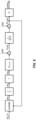
- a conventional PI controller is described, with reference to FIGs. 5A and 5B .
- C 1 is the proportional gain and T I the integration time.
- 1/s is the Laplace transform of an integration operation in time. It can be noted that since the controller has two free tuning parameters, the proportional gain and the integration time, arbitrary pole locations can be assigned to any second order feedback loop. Such pole-placement design will be applied to determine the controller in the power back-off control feature.
- the example controller described below will make use of the realization of PI control illustrated in Figure 5B , which factors out an integrator. That integrator may be placed in or close to the scheduler, to produce the desired dynamics of the resource limiting threshold as will be described below. As can be seen in Figure 5B , the remaining dynamics of the PI-controller resembles a proportional term and a differentiating term. That's why the solution applied average power back-off control is PD control together with an integrating resource limiting threshold.
- the dynamic resource threshold In order to obtain a smooth behavior of the dynamic resource threshold applied in the scheduler to limit the average output power, it needs to be rate controlled. This means that the control signal commands adjustments to the limiter, making it increase or decrease.
- the dynamic resource threshold is decoupled from the scheduler algorithms themselves, it just expresses a fractional limitation of the scheduler not to use more than a fraction y(t) of its total resources. Details on how this is done are described in detail below.
- the maximum value of y(t) is 1.0 since it is to express a fraction of the total amount of scheduler resources. There is also a need to limit its lower value, to avoid that the dynamic feedback control mechanism reduces it to an unphysical value below 0.0.
- the following scheduler threshold limitation is therefore applied at each time. ⁇ low ⁇ ⁇ t ⁇ 1.0
- the total momentary output power applied to an antenna array can be measured in the radio, just before the antenna. In one embodiment this can be done by couplers that measure the radio signal amplitude at each signal path to an antenna element. These amplitudes can then be combined into a total output power of the radio, with the antenna gain removed.
- a simpler, but less accurate alternative would be to replace the measured power by a predicted output power using information available in the scheduler or elsewhere in base band. Such a quantity could be easily obtained, e.g. by summing up the momentary scheduled power as estimated by the fraction of resource elements (REs) or physical resource blocks (PRBs) used at each time instant, over the time T.
- REs resource elements
- PRBs physical resource blocks
- This approach is however subject to a number of errors. These include, for example: the actual power errors caused by re-transmissions, power boosting and power sharing between transmission layers errors, as well as errors caused by radio signal processing close to the antenna, including e.g. clipping to achieve peak to average power reductions, and antenna alignment errors.
- Figure 6 is a block diagram illustrating a feedback control mechanism in which feedback control is enabled by a supervision mechanism as described below.
- ⁇ P tot ⁇ ref denotes the setpoint for the averaged power (typically slightly less than the threshold value determined to meet the regulatory RF EMF limit at a certain distance), 1/s denotes the actuator dynamics with lower and upper limits inactive, ⁇ ( t ) denotes the scheduler limitation after lower and upper limitation (inactive in Figure A3), P max,site denotes the maximal total power of the site, w(t) denotes a disturbance representing predicted power errors, 1 / (sT + 1) represents an autoregressive simplified model of the averaging, ⁇ P tot ⁇ ( s ) denotes the averaged total power, e(s) denotes a measurement error, G denotes the antenna gain and EIRP ( s ) denotes the EIRP. Note that all quantities are here expressed in the Laplace transform domain, which is allowed since the feedback control mechanism design is performed with constraints inactive. The momentary power described above is denoted P tot ( s ).
- w ( s ) and e ( s ) are not incorporated in any disclosed embodiments of the present invention, they are used herein as mathematical approximations of errors in the control loop, and are useful to assess performance aspects of embodiments of the present invention.
- This controller is of proportional - derivative (PD) type.
- C denotes the proportional gain
- T D the differentiation time.
- a reason for this choice is that a system with two negative real poles can be expected to be well damped, which is a result of a significant differentiation action. Since differentiation action is needed for fast back-off close to the determined threshold, this is the preferred design choice.
- Some additional modification of the controller may be made to adapt to the one-sided power back-off control problem formulation. This includes only allowing negative differentiation control, and a hard safety limit applied in case the average power gets too close to the regulatory threshold.
- ⁇ P tot ⁇ ref , ⁇ P tot ⁇ ( t ) and ⁇ P tot ⁇ ⁇ t are needed. Techniques for obtaining ⁇ P tot ⁇ ( t ) and ⁇ P tot ⁇ ⁇ t are described below.
- T S denotes the sampling period
- q T S ⁇ 1 is the one step delay operator. It is stressed that this implicitly assumes regular sampling in time, with very little jitter. Sampling cannot be event based. Therefore, a system clock is needed to drive the discrete time feedback control loop.
- the resource grid consists of a time-frequency division of radio resources that the scheduler has at its disposal, for scheduling of data to each user.
- a physical resource block PRB
- PRB comprises a set of sub-carriers on a defined frequency spacing.
- the PRB comprises 12 sub-carriers on a 30kHz spacing, for example.
- 7 OFDM symbols are transmitted within a slot having a defined period, such as 1mSec. for example.
- Each time-frequency location within the resource grid is referred to as a resource element (RE).
- RE resource element
- a Control Step encompassing a predefined number of slots (or subframes, as desired), and a Control Window encompassing a predefined number of control steps.
- a control window may be defined as having a period of 6 minutes, which is the averaging time up to 10 GHz specified in RF EMF exposure regulations based on the ICNIRP guidelines.
- the control window may be divided into 600 control steps, each of which will thus have a period of 0.6 seconds.
- each control step will therefore encompass 600 slots (or 300 sub-frames).
- the smallest schedulable entity in the time domain is the slot, while in the frequency domain, the smallest schedulable entity is the PRB.
- the average power controller then needs to be able to operate in a manner consistent with the worst case (i.e. lowest power) when using the minimum amount of PRBs. This is because the reference value set for the controller must be achievable in closed loop operation. If the worst case minimum power would be higher than the reference value, the controller would never be able to reach its target, which could result in unstable behavior or in so called integrator windup. Hence the following requirement needs to be met: ⁇ P tot ⁇ ref > ⁇ low P max , site
- the controller needs to be able to regulate signals both below and above the reference value. Therefore the reference value needs to be lower than the configured average power limit ⁇ P max,site where ⁇ is the fraction of the maximum power of the site, P max,site , that is configured by the operator for the site. If the reference value factor is denoted by 0 ⁇ ⁇ ⁇ 1, it holds that ⁇ P max , site > ⁇ low P max , site
- An aspect of the present invention provides time averaged blanking of slots to enable regulation below ⁇ low .
- “blanking of slots” means that downlink data (e.g. PDSCH) is not scheduled in a blanked slot, although other signaling (such as control data, synchronization signals and reference signals) may be unaffected.
- PDSCH downlink data
- other signaling such as control data, synchronization signals and reference signals
- the time averaged PDSCH power can be regulated down to a factor of 1 / N of the PDSCH power that was the lower range limit based on the minimum schedulable granularity discussed above.
- ⁇ low is multiplied by 1 / N since there are both control channel power that is proportional to the PDSCH power, and that are independent of PDSCH, thereby needing treatment as a constant.
- An example algorithm that enables range extension by time-averaged blanking may then operate as follows:
- PDSCH traffic can be scheduled in a maximum of n PRBs ( t ) PRBs in at total of k blanking ( t ) of the N slots of the control step; and no PDSCH traffic can be scheduled in N - k blanking ( t ) of the N slots of the control step.
- n PRBs ( t ) is the number of PRBs that are scheduled for a non blanked slot; n PRBs,total is the total number of PDSCH PRBs in one slot, n granularity is the minimum scheduling granularity (i.e. the minimum number of PRBs that may be scheduled in any given slot), and k blanking ( t ) is the number of slots that are not blanked, out of the N slots of the control step.
- Any suitable method may be implemented in the scheduler to determine which particular slots of the control step are blanked.
- the minimum scheduling granularity may be selected to be higher or lower than eight (e.g. 16). This would result in an increase of ⁇ low .
- the predictive time-averaged power control algorithm described above is motivated by a need to ensure algorithmically that the regulated time-averaged power is always below the average power threshold computed based on the designed RF EMF compliance boundary (exclusion zone) of the transmitter.
- the PI controller functionality described above does not have this property. This is because linear control, like PD control, is not designed to provide such guarantees.
- a conventional level-based safety limit does not have this property either, because it only falls back to use a fraction ⁇ low of the maximum power in case the regulated average power gets very close to the limit that is not to be exceeded. As may be seen in Figure 8 , there may still be overshoots.
- the next step is to answer the key question, using a computationally efficient algorithm. Towards that end figures 10A and 10B are useful.
- the momentary output power that is, the actual EIRP in each slot
Landscapes
- Engineering & Computer Science (AREA)
- Computer Networks & Wireless Communication (AREA)
- Signal Processing (AREA)
- Mobile Radio Communication Systems (AREA)
Claims (11)
- Verfahren zur Steuerung eines Funksenders in einem Drahtlosnetzwerk, wobei das Verfahren umfasst:Bestimmen (902) in jedem von einer Mehrzahl von aufeinanderfolgenden Steuerschritten, die sich über ein vorgegebenes Steuerfenster erstrecken, eines ersten Grenzwerts, der eine Anzahl von physikalischen Ressourcenblöcken, PRBs, darstellt, die in jedem von einer Mehrzahl von aufeinanderfolgenden zukünftigen Schlitzen eines aktuellen Steuerschritts disponiert werden kann, wenigstens zum Teil basierend auf einer zulässigen mittleren Ausgangsleistung des Funksenders, wobei das Steuerfenster eine Mehrzahl von Steuerschritten umfasst und jeder Steuerschritt eine Mehrzahl von Schlitzen umfasst;Disponieren (906) von PRBs in einem Anteil der Mehrzahl von aufeinanderfolgenden zukünftigen Schlitzen des aktuellen Steuerschritts, wenn der bestimmte erste Grenzwert kleiner oder gleich einem vorkonfigurierten zweiten Grenzwert ist, der eine Anzahl von PRBs darstellt, die in einem einzigen Schlitz (904) disponiert werden kann, wobei der Anteil so berechnet wird, dass ein gemittelter Teil von disponierten PRBs im aktuellen Steuerschritt kleiner oder gleich dem ersten Grenzwert ist,wobei der erste Grenzwert einen jeweiligen ersten Teil einer Gesamtanzahl von PRBs des Drahtlosnetzwerks umfasst, undwobei der zweite Grenzwert einen jeweiligen zweiten Teil einer Gesamtanzahl von PRBs des Drahtlosnetzwerks umfasst.
- Verfahren nach Anspruch 1, wobei das Bestimmen des ersten Grenzwerts umfasst:Berechnen einer zulässigen mittleren Ausgangsleistung des Funksenders über eine Mehrzahl von aufeinanderfolgenden zukünftigen Steuerschritten wenigstens zum Teil basierend auf einem Profil der Ausgangsleistung des Funksenders über eine vorgegebene Mehrzahl vergangener Steuerschritte und zukünftiger momentaner Ausgangsleistungen des Funksenders, die so begrenzt werden, dass sie gleich wie oder kleiner als eine vorgegebene mittlere Ausgangsleistung des Funksenders sind; undBestimmen der maximalen Anzahl von PRBs, die disponiert werden kann, wenigstens zum Teil basierend auf der berechneten zulässigen mittleren Ausgangsleistung und einem Referenzwert der vorgegebenen mittleren Ausgangsleistung.
- Verfahren nach Anspruch 2, wobei das Berechnen einer zulässigen mittleren Ausgangsleistung des Funksenders ein rekursives Berechnen für jeden Wert eines Index i beginnend bei i = N - 1 und dekrementierend auf i = 2 umfasst;

 〈Ptot 〉(t 0+iTS ) die zulässige mittlere Ausgangsleistung des Funksenders im i-ten zukünftigen Steuerschritt ist;t 0 eine Zeitreferenz eines aktuellen Steuerschritts ist;TS eine Dauer jedes Steuerschritts ist;aPmax,site die vorgegebene mittlere Ausgangsleistung des Funksenders ist;N die Anzahl von aufeinanderfolgenden zukünftigen Steuerschritten ist; undPbackward,i der Wert des Ausgangsleistungsprofils in einem vergangenen Steuerschritt ist, der mit dem i-ten zukünftigen Steuerschritt assoziiert ist.
 - Verfahren nach Anspruch 2, wobei der Referenzwert der vorgegebenen mittleren Ausgangsleistung (εPmax,site - e) ist, wobei ε ein vorgegebener relativer Schwellenwert ist und e eine vorgegebene Toleranz ist, und wobei das Bestimmen der maximalen Anzahl von PRBs, die disponiert werden kann, ein Festlegen der maximalen Anzahl von PRBs, die im i-ten zukünftigen Schritt disponiert werden kann, auf einen harten Grenzwert umfasst, der dem Referenzwert der vorgegebenen mittleren Ausgangsleistung entspricht, wenn die zulässige mittlere Ausgangsleistung des Funksenders im i-ten zukünftigen Steuerschritt größer als der Referenzwert der vorgegebenen mittleren Ausgangsleistung ist.
- Verfahren nach Anspruch 1, wobei eine Untergrenze von PRBs, die in einem einzigen Schlitz disponiert werden können, ein ganzzahliges Vielfaches einer Frequenzdomänen-Dispositionsgranularität ist.
- Verfahren nach Anspruch 5, wobei die Frequenzdomänen-Dispositionsgranularität gleich mindestens zwei PRBs ist.
- Verfahren nach Anspruch 6, wobei die Frequenzdomänen-Dispositionsgranularität gleich acht PRBs ist.
- Verfahren nach Anspruch 1, wobei das Disponieren von PRBs in dem Anteil der Mehrzahl von aufeinanderfolgenden zukünftigen Schlitzen umfasst:Disponieren eines Physical Downlink Shared Channel, PDSCH, in höchstens nPRBs (t) PRBs in kblanking (t) von N zukünftigen Schlitzen; undDisponieren keines PDSCH in [N - kblanking (t) 1 der N zukünftigen Schlitze;wobei:nPRBs(t) die Anzahl von PRBs ist, die für einen nicht ausgeblendeten Schlitz disponiert wird;nPRBs,total die Gesamtanzahl von PRBs in einem Schlitz ist;ngranularity die Mindestanzahl von PRBs, ist die in jedem Schlitz disponiert werden kann;N die Anzahl von zukünftigen Schlitzen ist; undkblanking(t) die Anzahl der nicht ausgeblendeten Schlitze der N zukünftigen aufeinanderfolgenden Schlitzen ist.
- Verfahren nach Anspruch 8, wobei die Anzahl der nicht ausgeblendeten Schlitze der N zukünftigen Schlitze Folgendem entspricht:
 γ(t) der erste Grenzwert ist; undγlow der zweite Grenzwert ist.
 - Netzwerkknoten, umfassend:mindestens einen Prozessor; undein nicht-transitorisches maschinenlesbares Speichermedium, das Softwareanweisungen umfasst, die so konfiguriert sind, dass sie den mindestens einen Prozessor zum Implementieren eines Verfahrens zur Steuerung eines Funksenders steuern, wobei das Verfahren umfasst:Bestimmen in jedem von einer Mehrzahl von aufeinanderfolgenden Steuerschritten, die sich über ein vorgegebenes Zeitfenster erstrecken, eines ersten Grenzwerts, der eine Anzahl von physikalischen Ressourcenblöcken, PRBs, darstellt, die in jedem von einer Mehrzahl von aufeinanderfolgenden zukünftigen Schlitzen eines aktuellen Steuerschritts disponiert werden kann, wenigstens zum Teil basierend auf einer zulässigen mittleren Ausgangsleistung des Funksenders, wobei das Steuerfenster eine Mehrzahl von Steuerschritten umfasst und jeder Steuerschritt eine Mehrzahl von Schlitzen umfasst;Disponieren von PRBs in einem Anteil der Mehrzahl von aufeinanderfolgenden zukünftigen Schlitzen des aktuellen Steuerschritts, wenn der bestimmte erste Grenzwert kleiner oder gleich einem vorkonfigurierten zweiten Grenzwert ist, der eine Anzahl von PRBs darstellt, die in einem einzigen Schlitz disponiert werden kann, wobei der Anteil so berechnet wird, dass ein gemittelter Teil von disponierten PRBs im aktuellen Steuerschritt kleiner oder gleich dem ersten Grenzwert ist,wobei der erste Grenzwert einen jeweiligen ersten Teil einer Gesamtanzahl von PRBs des Drahtlosnetzwerks umfasst, undwobei der zweite Grenzwert einen jeweiligen zweiten Teil einer Gesamtanzahl von PRBs des Drahtlosnetzwerks umfasst.
- Nicht-transitorisches maschinenlesbares Speichermedium, das Softwareanweisungen umfasst, die so konfiguriert sind, dass sie mindestens einen Prozessor eines Netzwerkknotens steuern, und die bei Ausführung durch den Prozessor den Netzwerkknoten zum Implementieren eines Verfahrens zur Steuerung eines Funksenders veranlassen, wobei das Verfahren umfasst:Bestimmen in jedem von einer Mehrzahl von aufeinanderfolgenden Steuerschritten, die sich über ein vorgegebenes Zeitfenster erstrecken, eines ersten Grenzwerts, der eine Anzahl von physikalischen Ressourcenblöcken, PRBs, darstellt, die in jedem von einer Mehrzahl von aufeinanderfolgenden zukünftigen Schlitzen eines aktuellen Steuerschritts disponiert werden kann, wenigstens zum Teil basierend auf einer zulässigen mittleren Ausgangsleistung des Funksenders, wobei das Steuerfenster eine Mehrzahl von Steuerschritten umfasst und jeder Steuerschritt eine Mehrzahl von Schlitzen umfasst;Disponieren von PRBs in einem Anteil der Mehrzahl von aufeinanderfolgenden zukünftigen Schlitzen des aktuellen Steuerschritts, wenn der bestimmte erste Grenzwert kleiner oder gleich einem vorkonfigurierten zweiten Grenzwert ist, der eine Anzahl von PRBs darstellt, die in einem einzigen Schlitz disponiert werden kann, wobei der Anteil so berechnet wird, dass ein gemittelter Teil von disponierten PRBs im aktuellen Steuerschritt kleiner oder gleich dem ersten Grenzwert ist,wobei der erste Grenzwert einen jeweiligen ersten Teil einer Gesamtanzahl von PRBs des Drahtlosnetzwerks umfasst, undwobei der zweite Grenzwert einen jeweiligen zweiten Teil einer Gesamtanzahl von PRBs des Drahtlosnetzwerks umfasst.
Applications Claiming Priority (1)
| Application Number | Priority Date | Filing Date | Title |
|---|---|---|---|
| PCT/IB2019/058532 WO2021069953A1 (en) | 2019-10-07 | 2019-10-07 | Average eirp regulation interval enhancement by time blanked scheduling |
Publications (2)
| Publication Number | Publication Date |
|---|---|
| EP4042756A1 EP4042756A1 (de) | 2022-08-17 |
| EP4042756B1 true EP4042756B1 (de) | 2024-07-17 |
Family
ID=68290018
Family Applications (1)
| Application Number | Title | Priority Date | Filing Date |
|---|---|---|---|
| EP19790078.0A Active EP4042756B1 (de) | 2019-10-07 | 2019-10-07 | Verbesserung des durchschnittlichen eirp-regelintervalls durch zeitausgeblendete planung |
Country Status (4)
| Country | Link |
|---|---|
| US (1) | US12096381B2 (de) |
| EP (1) | EP4042756B1 (de) |
| CN (1) | CN114451024B (de) |
| WO (1) | WO2021069953A1 (de) |
Families Citing this family (3)
| Publication number | Priority date | Publication date | Assignee | Title |
|---|---|---|---|---|
| EP4150976B1 (de) | 2020-05-11 | 2026-01-28 | Telefonaktiebolaget Lm Ericsson (Publ) | Koordinierte steuerung der durchschnittlichen eirp |
| WO2022271056A1 (en) * | 2021-06-23 | 2022-12-29 | Telefonaktiebolaget Lm Ericsson (Publ) | Controlling total average transmission power of a radio base station |
| EP4236489A1 (de) * | 2022-02-25 | 2023-08-30 | Nokia Solutions and Networks Oy | Verfahren und vorrichtung zur steuerung der funkemissionen einer basisstation |
Family Cites Families (25)
| Publication number | Priority date | Publication date | Assignee | Title |
|---|---|---|---|---|
| US8537948B2 (en) * | 2011-11-02 | 2013-09-17 | Telefonaktiebolaget L M Ericsson (Publ) | Clock synchronization in shared baseband deployments |
| US8811213B1 (en) * | 2012-02-24 | 2014-08-19 | Sprint Communications Company, L.P. | Avoiding satellite interference to long term evolution systems |
| EP2850887A1 (de) * | 2012-05-07 | 2015-03-25 | Telefonaktiebolaget LM Ericsson (PUBL) | Verfahren und anordnungen zur steuerung der übertragungsleistung in einer funkbasisstation |
| EP2862387B1 (de) * | 2012-06-19 | 2019-11-13 | Telefonaktiebolaget LM Ericsson (publ) | Knoten und methode zur ressourcenbuchung bei der zulassungskontrolle und planung mit dtx |
| CN103687042B (zh) * | 2012-09-03 | 2018-05-15 | 中兴通讯股份有限公司 | 一种物理下行共享信道的传输方法及系统 |
| CN106664667A (zh) * | 2014-09-05 | 2017-05-10 | 华为技术有限公司 | 用于控制基站的至少一个天线的射频发射的基站控制器 |
| US9622187B2 (en) | 2015-08-26 | 2017-04-11 | Qualcomm Incorporated | Real-time specific absorption rate implementation in wireless devices |
| US11039466B2 (en) * | 2016-10-28 | 2021-06-15 | Apple Inc. | User equipment (UE), evolved node-B (ENB) and methods for multiplexing new radio (NR) physical uplink shared channel (NR PUSCH) and NR physical uplink control channel (NR PUCCH) |
| EP3550910B1 (de) * | 2017-01-05 | 2021-04-28 | Guangdong Oppo Mobile Telecommunications Corp., Ltd. | Verfahren zur übertragung eines uplink-steuerkanals, netzwerkvorrichtung und endgerätevorrichtung |
| JP7100012B2 (ja) * | 2017-02-24 | 2022-07-12 | 株式会社Nttドコモ | 端末、無線通信方法、基地局及びシステム |
| US10298279B2 (en) * | 2017-04-05 | 2019-05-21 | Isco International, Llc | Method and apparatus for increasing performance of communication paths for communication nodes |
| US12114291B2 (en) * | 2017-11-10 | 2024-10-08 | Qualcomm Incorporated | Virtual resource block to physical resource block mapping in new radio |
| EP3711252B1 (de) * | 2017-11-17 | 2023-08-09 | Telefonaktiebolaget LM Ericsson (publ) | Konfiguration des "coreset" der verbleibenden minimalen systeminformation in einem neuen physikalischen rundfunkkanal |
| US11025456B2 (en) * | 2018-01-12 | 2021-06-01 | Apple Inc. | Time domain resource allocation for mobile communication |
| EP3518587B1 (de) * | 2018-01-26 | 2022-04-06 | Nokia Solutions and Networks Oy | Regelung von sendeleistungen von knoten |
| WO2020060089A1 (ko) * | 2018-09-21 | 2020-03-26 | 엘지전자 주식회사 | 하향링크 채널을 송수신하는 방법 및 이를 위한 장치 |
| US11133909B2 (en) * | 2018-11-30 | 2021-09-28 | T-Mobile Usa, Inc. | Scheduling HARQ transmissions in mini-slots based on fading conditions |
| US10790939B2 (en) * | 2018-11-30 | 2020-09-29 | T-Mobile Usa, Inc. | Selecting mini-slots according to conditions |
| US11233620B2 (en) * | 2018-11-30 | 2022-01-25 | T-Mobile Usa, Inc. | Scheduling HARQ transmissions in mini-slots |
| WO2020123162A1 (en) * | 2018-12-12 | 2020-06-18 | Intel Corporation | Dynamic transmit power adjustment |
| US11218412B2 (en) * | 2018-12-27 | 2022-01-04 | Flash Networks, Ltd | Method and system for managing the download of data |
| EP4654516A3 (de) * | 2019-02-22 | 2026-02-18 | InterDigital Patent Holdings, Inc. | Verfahren für nr-sl-multiunterkanal-pscch-übertragung |
| EP3817487B1 (de) * | 2019-11-04 | 2024-11-20 | Nokia Solutions and Networks Oy | Radio-mac-planung auf basis von fronthaul-transportkapazitätsbeschränkungen |
| EP4088515B1 (de) * | 2020-01-07 | 2026-03-04 | Telefonaktiebolaget LM Ericsson (publ) | Derivatbasierte harte grenzwertauslösung für die steuerung der durchschnittsleistung in einem aas |
| EP4179636A1 (de) * | 2020-07-10 | 2023-05-17 | Telefonaktiebolaget LM Ericsson (publ) | Dynamische elektromagnetische feldkoordination mehrerer träger |
-
2019
- 2019-10-07 US US17/641,981 patent/US12096381B2/en active Active
- 2019-10-07 CN CN201980101136.2A patent/CN114451024B/zh active Active
- 2019-10-07 EP EP19790078.0A patent/EP4042756B1/de active Active
- 2019-10-07 WO PCT/IB2019/058532 patent/WO2021069953A1/en not_active Ceased
Also Published As
| Publication number | Publication date |
|---|---|
| US12096381B2 (en) | 2024-09-17 |
| CN114451024B (zh) | 2024-08-13 |
| CN114451024A (zh) | 2022-05-06 |
| EP4042756A1 (de) | 2022-08-17 |
| WO2021069953A1 (en) | 2021-04-15 |
| US20240049149A1 (en) | 2024-02-08 |
Similar Documents
| Publication | Publication Date | Title |
|---|---|---|
| US12471027B2 (en) | Techniques for managing exposure using uplink duty cycling | |
| CN113597799B (zh) | 用于调整波束赋形简档的设备、方法和计算机可读介质 | |
| CN103828466B (zh) | 无线电网络节点、控制无线电网络节点及用于实现对无线电通信网络中的无线电资源的管理的方法 | |
| CN112534888A (zh) | 上行链路传输功率分配 | |
| US11412523B2 (en) | Controlling transmitter output in a wireless communications network based on regulatory RF exposure limits | |
| EP4042756B1 (de) | Verbesserung des durchschnittlichen eirp-regelintervalls durch zeitausgeblendete planung | |
| WO2015187071A1 (en) | Method and user equipment for predicting available throughput for uplink data | |
| WO2023028957A1 (en) | Resource allocation for co-channel coexistence | |
| WO2021220036A1 (en) | Predictive sectorized average power control | |
| US11595071B2 (en) | Controlling transmitter output | |
| US9426814B2 (en) | Radio base station and a method therein for scheduling radio resources based on a path loss fraction | |
| EP3963740B1 (de) | Koordinierte regelung des durchschnittlichen eirp mehrerer funksender | |
| CN119213710A (zh) | 具有准地面固定小区的非陆地网络中的信号测量 | |
| US20250056299A1 (en) | Minimizing interference between terrestrial network signals and non-terrestrial network signals | |
| CN109792692A (zh) | 针对短tti的上行链路功率优先化 | |
| US12470355B2 (en) | ACK coalescing performance through dynamic stream selection | |
| US12267859B2 (en) | Resource allocation in MU-MIMO OFDMA wireless systems | |
| WO2024050208A1 (en) | Techniques for beam selection with uplink consideration | |
| WO2024006605A1 (en) | Power control mechanism for positioning | |
| EP4055911B1 (de) | Präemptive unterdrückung von interzelleninterferenz in mobilfunkkommunikationsnetzen | |
| Ramesh et al. | A novel MAC scheduling algorithm for TCP throughput improvement in LTE system | |
| Assaf | Performance analysis of prioritization in LTE networks with the Vienna LTE system level simulator | |
| WO2025210169A1 (en) | Enhancements of measuring and reporting | |
| WO2025210165A1 (en) | Enhancements of measuring and reporting | |
| US10129882B1 (en) | Systems and methods for allocating resource blocks based on uplink transmission parameters |
Legal Events
| Date | Code | Title | Description |
|---|---|---|---|
| STAA | Information on the status of an ep patent application or granted ep patent |
Free format text: STATUS: UNKNOWN |
|
| STAA | Information on the status of an ep patent application or granted ep patent |
Free format text: STATUS: THE INTERNATIONAL PUBLICATION HAS BEEN MADE |
|
| PUAI | Public reference made under article 153(3) epc to a published international application that has entered the european phase |
Free format text: ORIGINAL CODE: 0009012 |
|
| STAA | Information on the status of an ep patent application or granted ep patent |
Free format text: STATUS: REQUEST FOR EXAMINATION WAS MADE |
|
| 17P | Request for examination filed |
Effective date: 20220210 |
|
| AK | Designated contracting states |
Kind code of ref document: A1 Designated state(s): AL AT BE BG CH CY CZ DE DK EE ES FI FR GB GR HR HU IE IS IT LI LT LU LV MC MK MT NL NO PL PT RO RS SE SI SK SM TR |
|
| DAV | Request for validation of the european patent (deleted) | ||
| DAX | Request for extension of the european patent (deleted) | ||
| GRAP | Despatch of communication of intention to grant a patent |
Free format text: ORIGINAL CODE: EPIDOSNIGR1 |
|
| STAA | Information on the status of an ep patent application or granted ep patent |
Free format text: STATUS: GRANT OF PATENT IS INTENDED |
|
| INTG | Intention to grant announced |
Effective date: 20240325 |
|
| GRAS | Grant fee paid |
Free format text: ORIGINAL CODE: EPIDOSNIGR3 |
|
| GRAA | (expected) grant |
Free format text: ORIGINAL CODE: 0009210 |
|
| STAA | Information on the status of an ep patent application or granted ep patent |
Free format text: STATUS: THE PATENT HAS BEEN GRANTED |
|
| AK | Designated contracting states |
Kind code of ref document: B1 Designated state(s): AL AT BE BG CH CY CZ DE DK EE ES FI FR GB GR HR HU IE IS IT LI LT LU LV MC MK MT NL NO PL PT RO RS SE SI SK SM TR |
|
| REG | Reference to a national code |
Ref country code: CH Ref legal event code: EP |
|
| REG | Reference to a national code |
Ref country code: DE Ref legal event code: R096 Ref document number: 602019055412 Country of ref document: DE |
|
| REG | Reference to a national code |
Ref country code: IE Ref legal event code: FG4D |
|
| REG | Reference to a national code |
Ref country code: LT Ref legal event code: MG9D |
|
| REG | Reference to a national code |
Ref country code: NL Ref legal event code: MP Effective date: 20240717 |
|
| PG25 | Lapsed in a contracting state [announced via postgrant information from national office to epo] |
Ref country code: PT Free format text: LAPSE BECAUSE OF FAILURE TO SUBMIT A TRANSLATION OF THE DESCRIPTION OR TO PAY THE FEE WITHIN THE PRESCRIBED TIME-LIMIT Effective date: 20241118 |
|
| REG | Reference to a national code |
Ref country code: AT Ref legal event code: MK05 Ref document number: 1705275 Country of ref document: AT Kind code of ref document: T Effective date: 20240717 |
|
| PG25 | Lapsed in a contracting state [announced via postgrant information from national office to epo] |
Ref country code: NL Free format text: LAPSE BECAUSE OF FAILURE TO SUBMIT A TRANSLATION OF THE DESCRIPTION OR TO PAY THE FEE WITHIN THE PRESCRIBED TIME-LIMIT Effective date: 20240717 |
|
| PG25 | Lapsed in a contracting state [announced via postgrant information from national office to epo] |
Ref country code: PT Free format text: LAPSE BECAUSE OF FAILURE TO SUBMIT A TRANSLATION OF THE DESCRIPTION OR TO PAY THE FEE WITHIN THE PRESCRIBED TIME-LIMIT Effective date: 20241118 Ref country code: NL Free format text: LAPSE BECAUSE OF FAILURE TO SUBMIT A TRANSLATION OF THE DESCRIPTION OR TO PAY THE FEE WITHIN THE PRESCRIBED TIME-LIMIT Effective date: 20240717 |
|
| PG25 | Lapsed in a contracting state [announced via postgrant information from national office to epo] |
Ref country code: NO Free format text: LAPSE BECAUSE OF FAILURE TO SUBMIT A TRANSLATION OF THE DESCRIPTION OR TO PAY THE FEE WITHIN THE PRESCRIBED TIME-LIMIT Effective date: 20241017 |
|
| PG25 | Lapsed in a contracting state [announced via postgrant information from national office to epo] |
Ref country code: FI Free format text: LAPSE BECAUSE OF FAILURE TO SUBMIT A TRANSLATION OF THE DESCRIPTION OR TO PAY THE FEE WITHIN THE PRESCRIBED TIME-LIMIT Effective date: 20240717 Ref country code: PL Free format text: LAPSE BECAUSE OF FAILURE TO SUBMIT A TRANSLATION OF THE DESCRIPTION OR TO PAY THE FEE WITHIN THE PRESCRIBED TIME-LIMIT Effective date: 20240717 Ref country code: GR Free format text: LAPSE BECAUSE OF FAILURE TO SUBMIT A TRANSLATION OF THE DESCRIPTION OR TO PAY THE FEE WITHIN THE PRESCRIBED TIME-LIMIT Effective date: 20241018 |
|
| PG25 | Lapsed in a contracting state [announced via postgrant information from national office to epo] |
Ref country code: BG Free format text: LAPSE BECAUSE OF FAILURE TO SUBMIT A TRANSLATION OF THE DESCRIPTION OR TO PAY THE FEE WITHIN THE PRESCRIBED TIME-LIMIT Effective date: 20240717 |
|
| PG25 | Lapsed in a contracting state [announced via postgrant information from national office to epo] |
Ref country code: LV Free format text: LAPSE BECAUSE OF FAILURE TO SUBMIT A TRANSLATION OF THE DESCRIPTION OR TO PAY THE FEE WITHIN THE PRESCRIBED TIME-LIMIT Effective date: 20240717 |
|
| PG25 | Lapsed in a contracting state [announced via postgrant information from national office to epo] |
Ref country code: AT Free format text: LAPSE BECAUSE OF FAILURE TO SUBMIT A TRANSLATION OF THE DESCRIPTION OR TO PAY THE FEE WITHIN THE PRESCRIBED TIME-LIMIT Effective date: 20240717 Ref country code: IS Free format text: LAPSE BECAUSE OF FAILURE TO SUBMIT A TRANSLATION OF THE DESCRIPTION OR TO PAY THE FEE WITHIN THE PRESCRIBED TIME-LIMIT Effective date: 20241117 |
|
| PG25 | Lapsed in a contracting state [announced via postgrant information from national office to epo] |
Ref country code: HR Free format text: LAPSE BECAUSE OF FAILURE TO SUBMIT A TRANSLATION OF THE DESCRIPTION OR TO PAY THE FEE WITHIN THE PRESCRIBED TIME-LIMIT Effective date: 20240717 |
|
| PG25 | Lapsed in a contracting state [announced via postgrant information from national office to epo] |
Ref country code: RS Free format text: LAPSE BECAUSE OF FAILURE TO SUBMIT A TRANSLATION OF THE DESCRIPTION OR TO PAY THE FEE WITHIN THE PRESCRIBED TIME-LIMIT Effective date: 20241017 Ref country code: ES Free format text: LAPSE BECAUSE OF FAILURE TO SUBMIT A TRANSLATION OF THE DESCRIPTION OR TO PAY THE FEE WITHIN THE PRESCRIBED TIME-LIMIT Effective date: 20240717 |
|
| PG25 | Lapsed in a contracting state [announced via postgrant information from national office to epo] |
Ref country code: RS Free format text: LAPSE BECAUSE OF FAILURE TO SUBMIT A TRANSLATION OF THE DESCRIPTION OR TO PAY THE FEE WITHIN THE PRESCRIBED TIME-LIMIT Effective date: 20241017 Ref country code: PL Free format text: LAPSE BECAUSE OF FAILURE TO SUBMIT A TRANSLATION OF THE DESCRIPTION OR TO PAY THE FEE WITHIN THE PRESCRIBED TIME-LIMIT Effective date: 20240717 Ref country code: NO Free format text: LAPSE BECAUSE OF FAILURE TO SUBMIT A TRANSLATION OF THE DESCRIPTION OR TO PAY THE FEE WITHIN THE PRESCRIBED TIME-LIMIT Effective date: 20241017 Ref country code: LV Free format text: LAPSE BECAUSE OF FAILURE TO SUBMIT A TRANSLATION OF THE DESCRIPTION OR TO PAY THE FEE WITHIN THE PRESCRIBED TIME-LIMIT Effective date: 20240717 Ref country code: IS Free format text: LAPSE BECAUSE OF FAILURE TO SUBMIT A TRANSLATION OF THE DESCRIPTION OR TO PAY THE FEE WITHIN THE PRESCRIBED TIME-LIMIT Effective date: 20241117 Ref country code: HR Free format text: LAPSE BECAUSE OF FAILURE TO SUBMIT A TRANSLATION OF THE DESCRIPTION OR TO PAY THE FEE WITHIN THE PRESCRIBED TIME-LIMIT Effective date: 20240717 Ref country code: GR Free format text: LAPSE BECAUSE OF FAILURE TO SUBMIT A TRANSLATION OF THE DESCRIPTION OR TO PAY THE FEE WITHIN THE PRESCRIBED TIME-LIMIT Effective date: 20241018 Ref country code: FI Free format text: LAPSE BECAUSE OF FAILURE TO SUBMIT A TRANSLATION OF THE DESCRIPTION OR TO PAY THE FEE WITHIN THE PRESCRIBED TIME-LIMIT Effective date: 20240717 Ref country code: ES Free format text: LAPSE BECAUSE OF FAILURE TO SUBMIT A TRANSLATION OF THE DESCRIPTION OR TO PAY THE FEE WITHIN THE PRESCRIBED TIME-LIMIT Effective date: 20240717 Ref country code: BG Free format text: LAPSE BECAUSE OF FAILURE TO SUBMIT A TRANSLATION OF THE DESCRIPTION OR TO PAY THE FEE WITHIN THE PRESCRIBED TIME-LIMIT Effective date: 20240717 Ref country code: AT Free format text: LAPSE BECAUSE OF FAILURE TO SUBMIT A TRANSLATION OF THE DESCRIPTION OR TO PAY THE FEE WITHIN THE PRESCRIBED TIME-LIMIT Effective date: 20240717 |
|
| PG25 | Lapsed in a contracting state [announced via postgrant information from national office to epo] |
Ref country code: DK Free format text: LAPSE BECAUSE OF FAILURE TO SUBMIT A TRANSLATION OF THE DESCRIPTION OR TO PAY THE FEE WITHIN THE PRESCRIBED TIME-LIMIT Effective date: 20240717 Ref country code: RO Free format text: LAPSE BECAUSE OF FAILURE TO SUBMIT A TRANSLATION OF THE DESCRIPTION OR TO PAY THE FEE WITHIN THE PRESCRIBED TIME-LIMIT Effective date: 20240717 Ref country code: SM Free format text: LAPSE BECAUSE OF FAILURE TO SUBMIT A TRANSLATION OF THE DESCRIPTION OR TO PAY THE FEE WITHIN THE PRESCRIBED TIME-LIMIT Effective date: 20240717 |
|
| REG | Reference to a national code |
Ref country code: DE Ref legal event code: R097 Ref document number: 602019055412 Country of ref document: DE |
|
| PG25 | Lapsed in a contracting state [announced via postgrant information from national office to epo] |
Ref country code: EE Free format text: LAPSE BECAUSE OF FAILURE TO SUBMIT A TRANSLATION OF THE DESCRIPTION OR TO PAY THE FEE WITHIN THE PRESCRIBED TIME-LIMIT Effective date: 20240717 |
|
| PG25 | Lapsed in a contracting state [announced via postgrant information from national office to epo] |
Ref country code: CZ Free format text: LAPSE BECAUSE OF FAILURE TO SUBMIT A TRANSLATION OF THE DESCRIPTION OR TO PAY THE FEE WITHIN THE PRESCRIBED TIME-LIMIT Effective date: 20240717 |
|
| PG25 | Lapsed in a contracting state [announced via postgrant information from national office to epo] |
Ref country code: SK Free format text: LAPSE BECAUSE OF FAILURE TO SUBMIT A TRANSLATION OF THE DESCRIPTION OR TO PAY THE FEE WITHIN THE PRESCRIBED TIME-LIMIT Effective date: 20240717 |
|
| PLBE | No opposition filed within time limit |
Free format text: ORIGINAL CODE: 0009261 |
|
| STAA | Information on the status of an ep patent application or granted ep patent |
Free format text: STATUS: NO OPPOSITION FILED WITHIN TIME LIMIT |
|
| REG | Reference to a national code |
Ref country code: CH Ref legal event code: PL |
|
| 26N | No opposition filed |
Effective date: 20250422 |
|
| PG25 | Lapsed in a contracting state [announced via postgrant information from national office to epo] |
Ref country code: MC Free format text: LAPSE BECAUSE OF FAILURE TO SUBMIT A TRANSLATION OF THE DESCRIPTION OR TO PAY THE FEE WITHIN THE PRESCRIBED TIME-LIMIT Effective date: 20240717 |
|
| PG25 | Lapsed in a contracting state [announced via postgrant information from national office to epo] |
Ref country code: LU Free format text: LAPSE BECAUSE OF NON-PAYMENT OF DUE FEES Effective date: 20241007 Ref country code: BE Free format text: LAPSE BECAUSE OF NON-PAYMENT OF DUE FEES Effective date: 20241031 |
|
| PG25 | Lapsed in a contracting state [announced via postgrant information from national office to epo] |
Ref country code: FR Free format text: LAPSE BECAUSE OF NON-PAYMENT OF DUE FEES Effective date: 20241031 |
|
| PG25 | Lapsed in a contracting state [announced via postgrant information from national office to epo] |
Ref country code: CH Free format text: LAPSE BECAUSE OF NON-PAYMENT OF DUE FEES Effective date: 20241031 |
|
| REG | Reference to a national code |
Ref country code: BE Ref legal event code: MM Effective date: 20241031 |
|
| PG25 | Lapsed in a contracting state [announced via postgrant information from national office to epo] |
Ref country code: SE Free format text: LAPSE BECAUSE OF FAILURE TO SUBMIT A TRANSLATION OF THE DESCRIPTION OR TO PAY THE FEE WITHIN THE PRESCRIBED TIME-LIMIT Effective date: 20240717 |
|
| PG25 | Lapsed in a contracting state [announced via postgrant information from national office to epo] |
Ref country code: IE Free format text: LAPSE BECAUSE OF NON-PAYMENT OF DUE FEES Effective date: 20241007 |
|
| PGFP | Annual fee paid to national office [announced via postgrant information from national office to epo] |
Ref country code: DE Payment date: 20251029 Year of fee payment: 7 |
|
| PGFP | Annual fee paid to national office [announced via postgrant information from national office to epo] |
Ref country code: GB Payment date: 20251027 Year of fee payment: 7 |
|
| PG25 | Lapsed in a contracting state [announced via postgrant information from national office to epo] |
Ref country code: CY Free format text: LAPSE BECAUSE OF FAILURE TO SUBMIT A TRANSLATION OF THE DESCRIPTION OR TO PAY THE FEE WITHIN THE PRESCRIBED TIME-LIMIT; INVALID AB INITIO Effective date: 20191007 Ref country code: IT Free format text: LAPSE BECAUSE OF FAILURE TO SUBMIT A TRANSLATION OF THE DESCRIPTION OR TO PAY THE FEE WITHIN THE PRESCRIBED TIME-LIMIT Effective date: 20240717 |
|
| PG25 | Lapsed in a contracting state [announced via postgrant information from national office to epo] |
Ref country code: HU Free format text: LAPSE BECAUSE OF FAILURE TO SUBMIT A TRANSLATION OF THE DESCRIPTION OR TO PAY THE FEE WITHIN THE PRESCRIBED TIME-LIMIT; INVALID AB INITIO Effective date: 20191007 |