EP4042984A1 - Attelle de genou et attelle de pied - Google Patents
Attelle de genou et attelle de pied Download PDFInfo
- Publication number
- EP4042984A1 EP4042984A1 EP22156040.2A EP22156040A EP4042984A1 EP 4042984 A1 EP4042984 A1 EP 4042984A1 EP 22156040 A EP22156040 A EP 22156040A EP 4042984 A1 EP4042984 A1 EP 4042984A1
- Authority
- EP
- European Patent Office
- Prior art keywords
- shank
- thigh
- cam
- pin
- knee joint
- Prior art date
- Legal status (The legal status is an assumption and is not a legal conclusion. Google has not performed a legal analysis and makes no representation as to the accuracy of the status listed.)
- Withdrawn
Links
Images


Classifications
-
- A—HUMAN NECESSITIES
- A61—MEDICAL OR VETERINARY SCIENCE; HYGIENE
- A61F—FILTERS IMPLANTABLE INTO BLOOD VESSELS; PROSTHESES; DEVICES PROVIDING PATENCY TO, OR PREVENTING COLLAPSING OF, TUBULAR STRUCTURES OF THE BODY, e.g. STENTS; ORTHOPAEDIC, NURSING OR CONTRACEPTIVE DEVICES; FOMENTATION; TREATMENT OR PROTECTION OF EYES OR EARS; BANDAGES, DRESSINGS OR ABSORBENT PADS; FIRST-AID KITS
- A61F5/00—Orthopaedic methods or devices for non-surgical treatment of bones or joints; Nursing devices ; Anti-rape devices
- A61F5/01—Orthopaedic devices, e.g. long-term immobilising or pressure directing devices for treating broken or deformed bones such as splints, casts or braces
- A61F5/0102—Orthopaedic devices, e.g. long-term immobilising or pressure directing devices for treating broken or deformed bones such as splints, casts or braces specially adapted for correcting deformities of the limbs or for supporting them; Ortheses, e.g. with articulations
- A61F5/0123—Orthopaedic devices, e.g. long-term immobilising or pressure directing devices for treating broken or deformed bones such as splints, casts or braces specially adapted for correcting deformities of the limbs or for supporting them; Ortheses, e.g. with articulations for the knees
-
- A—HUMAN NECESSITIES
- A61—MEDICAL OR VETERINARY SCIENCE; HYGIENE
- A61F—FILTERS IMPLANTABLE INTO BLOOD VESSELS; PROSTHESES; DEVICES PROVIDING PATENCY TO, OR PREVENTING COLLAPSING OF, TUBULAR STRUCTURES OF THE BODY, e.g. STENTS; ORTHOPAEDIC, NURSING OR CONTRACEPTIVE DEVICES; FOMENTATION; TREATMENT OR PROTECTION OF EYES OR EARS; BANDAGES, DRESSINGS OR ABSORBENT PADS; FIRST-AID KITS
- A61F5/00—Orthopaedic methods or devices for non-surgical treatment of bones or joints; Nursing devices ; Anti-rape devices
- A61F5/01—Orthopaedic devices, e.g. long-term immobilising or pressure directing devices for treating broken or deformed bones such as splints, casts or braces
- A61F5/0102—Orthopaedic devices, e.g. long-term immobilising or pressure directing devices for treating broken or deformed bones such as splints, casts or braces specially adapted for correcting deformities of the limbs or for supporting them; Ortheses, e.g. with articulations
- A61F2005/0132—Additional features of the articulation
- A61F2005/0146—Additional features of the articulation combining rotational and sliding movements, e.g. simulating movements of a natural joint
-
- A—HUMAN NECESSITIES
- A61—MEDICAL OR VETERINARY SCIENCE; HYGIENE
- A61F—FILTERS IMPLANTABLE INTO BLOOD VESSELS; PROSTHESES; DEVICES PROVIDING PATENCY TO, OR PREVENTING COLLAPSING OF, TUBULAR STRUCTURES OF THE BODY, e.g. STENTS; ORTHOPAEDIC, NURSING OR CONTRACEPTIVE DEVICES; FOMENTATION; TREATMENT OR PROTECTION OF EYES OR EARS; BANDAGES, DRESSINGS OR ABSORBENT PADS; FIRST-AID KITS
- A61F5/00—Orthopaedic methods or devices for non-surgical treatment of bones or joints; Nursing devices ; Anti-rape devices
- A61F5/01—Orthopaedic devices, e.g. long-term immobilising or pressure directing devices for treating broken or deformed bones such as splints, casts or braces
- A61F5/0102—Orthopaedic devices, e.g. long-term immobilising or pressure directing devices for treating broken or deformed bones such as splints, casts or braces specially adapted for correcting deformities of the limbs or for supporting them; Ortheses, e.g. with articulations
- A61F2005/0132—Additional features of the articulation
- A61F2005/0153—Additional features of the articulation combining rotational and stretching movements
-
- A—HUMAN NECESSITIES
- A61—MEDICAL OR VETERINARY SCIENCE; HYGIENE
- A61F—FILTERS IMPLANTABLE INTO BLOOD VESSELS; PROSTHESES; DEVICES PROVIDING PATENCY TO, OR PREVENTING COLLAPSING OF, TUBULAR STRUCTURES OF THE BODY, e.g. STENTS; ORTHOPAEDIC, NURSING OR CONTRACEPTIVE DEVICES; FOMENTATION; TREATMENT OR PROTECTION OF EYES OR EARS; BANDAGES, DRESSINGS OR ABSORBENT PADS; FIRST-AID KITS
- A61F5/00—Orthopaedic methods or devices for non-surgical treatment of bones or joints; Nursing devices ; Anti-rape devices
- A61F5/01—Orthopaedic devices, e.g. long-term immobilising or pressure directing devices for treating broken or deformed bones such as splints, casts or braces
- A61F5/0102—Orthopaedic devices, e.g. long-term immobilising or pressure directing devices for treating broken or deformed bones such as splints, casts or braces specially adapted for correcting deformities of the limbs or for supporting them; Ortheses, e.g. with articulations
- A61F2005/0132—Additional features of the articulation
- A61F2005/0155—Additional features of the articulation with actuating means
-
- A—HUMAN NECESSITIES
- A61—MEDICAL OR VETERINARY SCIENCE; HYGIENE
- A61F—FILTERS IMPLANTABLE INTO BLOOD VESSELS; PROSTHESES; DEVICES PROVIDING PATENCY TO, OR PREVENTING COLLAPSING OF, TUBULAR STRUCTURES OF THE BODY, e.g. STENTS; ORTHOPAEDIC, NURSING OR CONTRACEPTIVE DEVICES; FOMENTATION; TREATMENT OR PROTECTION OF EYES OR EARS; BANDAGES, DRESSINGS OR ABSORBENT PADS; FIRST-AID KITS
- A61F5/00—Orthopaedic methods or devices for non-surgical treatment of bones or joints; Nursing devices ; Anti-rape devices
- A61F5/01—Orthopaedic devices, e.g. long-term immobilising or pressure directing devices for treating broken or deformed bones such as splints, casts or braces
- A61F5/0102—Orthopaedic devices, e.g. long-term immobilising or pressure directing devices for treating broken or deformed bones such as splints, casts or braces specially adapted for correcting deformities of the limbs or for supporting them; Ortheses, e.g. with articulations
- A61F2005/0132—Additional features of the articulation
- A61F2005/0165—Additional features of the articulation with limits of movement
Definitions
- the present disclosure relates to a knee brace and a leg brace.
- Patent Literature 1 Japanese Utility Model No. H05-29707 discloses a knee brace that includes a structure including parts from a thigh part to a shank part and prevents a knee joint from being deformed by controlling movement of the knee joint.
- Knee joint flexion contracture has a symptom that the range of motion of a knee joint on an extension side is narrow, which results in a pain being caused in the knee joint when it is extended.
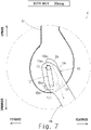
- Fig. 1 shows a side view of a normal knee joint. As shown in Fig. 1 , the femoral condyle of the femur and the upper joint surface of the shinbone are vertically opposed to each other. In Fig. 1 , “forward” means forward with respect to a patient and “rearward” means rearward with respect to the patient.
- Fig. 2 shows a side view of a knee joint with knee joint flexion contracture.
- the upper joint surface of the shinbone is displaced relatively rearward with respect to the femoral condyle of the femur.
- an appropriate sliding between the upper joint surface of the shinbone and the femoral condyle of the femur is inhibited, which results in a pain being caused in the knee joint.
- rehabilitation aimed at expanding the movable range of the knee joint on the extension side has been unendurable for patients.
- the aim of the present disclosure is to provide a technique for relieving pain that occurs when a knee joint with knee joint flexion contracture is extended.
- a knee brace including: a thigh attachment part that is attached to a thigh of a user; a shank attachment part that is attached to a shank of the user; an outer unit that couples the thigh attachment part to the shank attachment part and is arranged on an outer (lateral) side of a lower limb of the user; and an inner unit that couples the thigh attachment part to the shank attachment part and is arranged on an inner (medial) side of the lower limb of the user
- the outer unit includes: a thigh outer link that is extended along the thigh and is fixed to the thigh by the thigh attachment part; and a shank outer link that is extended along the shank and is fixed to the shank by the shank attachment part, the thigh outer link and the shank outer link are rotatably coupled to each other on the outer side of the knee joint of the user
- the inner unit includes: a thigh inner link that is extended along the thigh and is fixed to
- a thigh cam may be formed in the thigh outer link, a shank pin that is engaged with the thigh cam in such a way that the shank pin moves along the thigh cam may be formed in the shank outer link, a shank cam may be formed in the shank outer link, a thigh pin that is engaged with the shank cam in such a way that the thigh pin moves along the shank cam may be formed in the thigh outer link, and the shank cam may be extended rearward as it moves away from the shank attachment part, and the thigh cam may be formed in such a way that the shank attachment part moves away from the thigh pin as the knee joint is extended.
- the relative movement of the shank outer link with respect to the thigh outer link described above is achieved with a simple structure.
- a thigh cam may be formed in the thigh inner link, a shank pin that is engaged with the thigh cam in such a way that the shank pin moves along the thigh cam may be formed in the shank inner link, a shank cam may be formed in the shank inner link, a thigh pin that is engaged with the shank cam in such a way that the thigh pin moves along the shank cam may be formed in the thigh inner link, the shank cam may be extended rearward as it moves away from the shank attachment part, and the thigh cam may be formed in such a way that the shank attachment part moves away from the thigh pin as the knee joint is extended.
- the relative movement of the shank outer link with respect to the thigh outer link described above is achieved with a simple structure.
- the thigh cam may be formed in such a way that the shank attachment part moves away from the thigh pin while the knee joint angle is changed from 90 degrees to 0 degrees. According to the aforementioned structure, it is possible to efficiently relieve the pain at a timing when the pain occurs when the knee joint with knee joint flexion contracture is extended.
- the thigh cam may be formed in such a way that the shank attachment part moves away from the thigh pin while the knee joint angle is changed from 60 degrees to 30 degrees. According to the aforementioned structure, it is possible to efficiently relieve the pain at a timing when the pain occurs when the knee joint with knee joint flexion contracture is extended.
- a thigh cam may be formed in the thigh outer link, a shank pin that is engaged with the thigh cam in such a way that the shank pin moves along the thigh cam may be formed in the shank outer link, a shank cam may be formed in the shank outer link, a thigh pin that is engaged with the shank cam in such a way that the thigh pin moves along the shank cam may be formed in the thigh outer link, and the thigh cam may be extended forward as it moves away from the thigh attachment part, and the shank cam may be formed in such a way that the shank attachment part moves away from the thigh pin as the knee joint is extended.
- the relative movement of the shank outer link with respect to the thigh outer link described above is achieved with a simple structure.
- a thigh cam may be formed in the thigh inner link, a shank pin that is engaged with the thigh cam in such a way that the shank pin moves along the thigh cam may be formed in the shank inner link, a shank cam may be formed in the shank inner link, a thigh pin that is engaged with the shank cam in such a way that the thigh pin moves along the shank cam may be formed in the thigh inner link, the thigh cam may be extended forward as it moves away from the thigh attachment part, and the shank cam may be formed in such a way that the shank attachment part moves away from the thigh pin as the knee joint is extended.
- the relative movement of the shank outer link with respect to the thigh outer link described above is achieved with a simple structure.
- the shank cam may be formed in such a way that the shank attachment part moves away from the thigh pin while the knee joint angle is changed from 90 degrees to 0 degrees. According to the aforementioned structure, it is possible to efficiently relieve the pain at a timing when the pain occurs when the knee joint with knee joint flexion contracture is extended.
- the shank cam may be formed in such a way that the shank attachment part moves away from the thigh pin while the knee joint angle is changed from 60 degrees to 30 degrees. According to the aforementioned structure, it is possible to efficiently relieve the pain at a timing when the pain occurs when the knee joint with knee joint flexion contracture is extended.
- a leg brace including the above knee brace may be provided.
- the shinbone is pulled downward at a time of extension of the knee joint, whereby the gap between the femoral condyle of the femur and the upper joint surface of the shinbone is expanded.
- the phrase "the shinbone is pulled downward at a time of extension of the knee joint” means that the shinbone is pulled toward the foot side in the longitudinal direction of the shinbone when the knee joint is extended.
- the inventors of the present disclosure have made a knee brace that allows anyone to easily perform the above three movements, and further allows a patient to instead perform them by herself/himself.
- leg brace 1 according to a first embodiment will be described.
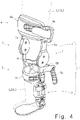
- Fig. 4 shows the leg brace 1 attached to the left leg L of a user.
- Fig. 4 shows the left leg L of the user by an alternate long and two short dashes line and shows the shoe that the user wears by an alternate long and short dash line.
- the leg brace 1 includes a knee brace 2 and a shank assisting tool 3.
- the knee brace 2 which is attached to the left leg L with knee osteoarthritis, is a brace that relieves pain that occurs when a knee joint with knee joint flexion contracture is extended.
- the knee brace 2, which is attached to the left leg L, is flexed following flexing of the knee joint.
- the shank assisting tool 3 prevents the thrust of the knee joint of the user.
- the description of the shank assisting tool 3 is omitted.
- the shank assisting tool 3 is configured in such a way that it can be attached to and detached from the knee brace 2. Therefore, the shank assisting tool 3 can be removed from the knee brace 2 and the knee brace 2 can be used alone.
- the knee brace 2 includes a thigh attachment part 4, a shank attachment part 5, an outer unit 6, and an inner unit 7.
- the thigh attachment part 4 is attached to the thigh L1 of the left leg L of the user.
- the thigh attachment part 4 includes a thigh cuff 4a and a thigh belt 4b.
- the thigh cuff 4a is arranged so as to be opposed to the front surface of the thigh L1 of the user.
- the thigh cuff 4a is curved to be convex toward the front in a plan view.
- the thigh belt 4b is wound around the thigh L1 of the user so that both the thigh L1 of the user and the thigh cuff 4a are concurrently wrapped in the thigh belt 4b, whereby the thigh cuff 4a is fixed to the thigh L1 of the user.
- the shank attachment part 5 is attached to the shank L2 of the left leg L of the user.
- the shank attachment part 5 includes a shank cuff 5a and a shank belt 5b.
- the shank cuff 5a is arranged so as to be opposed to the front surface of the shank L2 of the user.
- the shank cuff 5a is curved to be convex toward the front in a plan view.
- the shank belt 5b is wound around the shank L2 of the user so that both the shank L2 of the user and the shank cuff 5a are concurrently wrapped in the shank belt 5b, whereby the shank cuff 5a is fixed to the shank L2 of the user.
- the outer unit 6, which couples the thigh attachment part 4 to the shank attachment part 5, is arranged on the outer (lateral) side of the left leg L (lower limb) of the user.
- the outer unit 6 includes a thigh outer link 6a that is extended along the thigh L1 and is fixed to the thigh L1 by the thigh attachment part 4 and a shank outer link 6b that is extended along the shank L2 and is fixed to the shank L2 by the shank attachment part 5.
- the thigh outer link 6a and the shank outer link 6b are rotatably coupled to each other on the outer side of the knee joint of the user.
- the inner unit 7, which couples the thigh attachment part 4 to the shank attachment part 5, is arranged on the inner (medial) side of the left leg L (lower limb) of the user.
- the inner unit 7 includes a thigh inner link 7a that is extended along the thigh L1 and is fixed to the thigh L1 by the thigh attachment part 4 and a shank inner link 7b that is extended along the shank L2 and is fixed to the shank L2 by the shank attachment part 5.
- the thigh inner link 7a and the shank inner link 7b are rotatably coupled to each other on the inner side of the knee joint of the user.
- the outer unit 6 is configured in such a way that the shank outer link 6b moves away from the thigh outer link 6a in the longitudinal direction of the shank outer link 6b and the shank outer link 6b is drawn forward in a direction perpendicular to the longitudinal direction of the shank outer link 6b relative to the thigh outer link 6a as the knee joint of the user is extended.
- the inner unit 7 is configured in such a way that the shank inner link 7b moves away from the thigh inner link 7a in the longitudinal direction of the shank inner link 7b and the shank inner link 7b is drawn forward in the direction perpendicular to the longitudinal direction of the shank inner link 7b relative to the thigh inner link 7a as the knee joint of the user is extended. The details thereof will be described below.
- Fig. 5 shows a state in which the shank outer link 6b is detached from the thigh outer link 6a.
- Fig. 6 shows a state in which the shank outer link 6b is attached to the thigh outer link 6a.
- a thigh cam 10 is formed in the thigh outer link 6a.
- a shank pin 11 that is engaged with the thigh cam 10 in such a way that it moves along the thigh cam 10 is formed in the shank outer link 6b.
- a shank cam 12 is formed in the shank outer link 6b.
- a thigh pin 13 that is engaged with the shank cam 12 in such a way that it moves along the shank cam 12 is formed in the thigh outer link 6a.
- the shank outer link 6b is arranged on the outer side (on the front side of the paper) of the thigh outer link 6a.
- the shank outer link 6b may be arranged on the inner side (on the back side of the paper) of the thigh outer link 6a.
- the shank pin 11 is protruded toward the inner side and the thigh pin 13 is protruded toward the outer side.
- the thigh cam 10 is formed in the form of a groove that does not penetrate the thigh outer link 6a in the thickness direction of the thigh outer link 6a.
- the thigh cam 10 may be formed in the form of a slit that penetrates the thigh outer link 6a in the thickness direction of the thigh outer link 6a.
- the shank cam 12 is formed in the form of a slit that penetrates the shank outer link 6b in the thickness direction of the shank outer link 6b.
- the shank cam 12 may be formed in the form of a groove that does not penetrate the shank outer link 6b in the thickness direction of the shank outer link 6b.
- the thigh pin 13 moves along the shank cam 12 and the shank pin 11 moves along the thigh cam 10. That is, the thigh cam 10, the shank pin 11, the shank cam 12, and the thigh pin 13 work together so that the outer unit 6 is configured to be flexed following flexing of the knee joint.
- the shank cam 12 is extended rearward as it moves away from the shank attachment part 5.
- the shank cam 12 is extended rearward as it extends upward.
- the shank cam 12 is inclined with respect to the longitudinal direction of the shank cam 12.
- the shank cam 12 is linearly extended.
- the shank cam 12 may be curved so as to be convex toward the front or may be curved so as to be convex toward the rear side.
- the shank cam 12 includes an extending-side end part 12ex and a flexing-side end part 12bn.
- the extending-side end part 12ex is an end part where the thigh pin 13 is positioned when the knee joint is extended and the knee joint angle becomes 0 degrees.
- the flexing-side end part 12bn is an end part where the thigh pin 13 is positioned when the knee joint is flexed and the knee joint angle becomes 120 degrees. Therefore, when the knee joint is extended, the thigh pin 13 moves from the flexing-side end part 12bn toward the extending-side end part 12ex. On the other hand, when the knee joint is flexed, the thigh pin 13 moves from the extending-side end part 12ex toward the flexing-side end part 12bn.
- the shank pin 11 is arranged below the shank cam 12.
- the shank pin 11 is arranged closer to the shank attachment part 5 than to the shank cam 12.
- the thigh pin 13 when the thigh pin 13 is positioned in the flexing-side end part 12bn of the shank cam 12, the thigh pin 13 is made to come closest to the shank pin 11. In contrast, when the thigh pin 13 is positioned in the extending-side end part 12ex of the shank cam 12, the thigh pin 13 moves farthest away from the shank pin 11.
- the thigh cam 10 is formed in such a way that the shank attachment part 5 moves away from the thigh pin 13 as the knee joint is extended.
- the thigh cam 10 is formed in such a way that it functions to move the shank attachment part 5 away from the thigh pin 13 as the knee joint is extended.
- the thigh cam 10 is extended in a curved shape so as to surround the thigh pin 13.
- the thigh cam 10 is curved in a U-shape with an opening toward the front.
- the thigh cam 10 includes an extending-side end part 10ex and a flexing-side end part 10bn.
- the extending-side end part 10ex is an end part where the shank pin 11 is positioned when the knee joint is extended and the knee joint angle becomes 0 degrees.
- the flexing-side end part 10bn is an end part where the shank pin 11 is positioned when the knee joint is flexed and the knee joint angle becomes 120 degrees.
- the thigh cam 10 includes a flexing cam part 10a, a transition linear cam part 10b, a transition bending cam part 10c, and an extending cam part 10d.
- the flexing cam part 10a includes a flexing-side end part 10bn.
- the extending cam part 10d includes an extending-side end part 10ex.
- the flexing cam part 10a, the transition linear cam part 10b, the transition bending cam part 10c, and the extending cam part 10d are continuously formed in this order. Therefore, the flexing cam part 10a, the transition linear cam part 10b, the transition bending cam part 10c, and the extending cam part 10d are continuously formed in this order from the flexing-side end part 10bn toward the extending-side end part 10ex.
- the boundary between the flexing cam part 10a and the transition linear cam part 10b, the boundary between the transition linear cam part 10b and the transition bending cam part 10c, and the boundary between the transition bending cam part 10c and the extending cam part 10d are shown by alternate long and two short dashes lines.
- the flexing cam part 10a is arranged above the thigh pin 13 and is extended in an arc shape with the center of the thigh pin 13. That is, the flexing cam part 10a is curved so as to be convex upward.
- the transition linear cam part 10b is arranged in the rear of the thigh pin 13 and is linearly extended.
- the transition linear cam part 10b is extended rearward as it is extended downward. Therefore, the transition linear cam part 10b is formed in such a manner that it moves away from the thigh pin 13 from the side of the flexing-side end part 10bn to the side of the extending-side end part 10ex.
- the transition bending cam part 10c is arranged below and in the rear of the thigh pin 13, and is extended in an arc shape around the center of curvature 10cc located below the thigh pin 13. That is, the transition bending cam part 10c is curved so as to be convex in the direction away from the thigh pin 13, in other words, so as to be convex downwardly and rearwardly. Therefore, the transition bending cam part 10c is formed in such a way that it moves away from the thigh pin 13 from the side of the flexing-side end part 10bn to the side of the extending-side end part 10ex.
- the extending cam part 10d is arranged below the thigh pin 13 and is linearly extended.
- the extending cam part 10d is extended in the front-back direction. Therefore, the extending cam part 10d is made to slightly come close to the thigh pin 13 from the side of the flexing-side end part 10bn to the side of the extending-side end part 10ex, and then it slightly moves away from the thigh pin 13.
- the thigh pin 13 is positioned in the extending-side end part 12ex of the shank cam 12 and the shank pin 11 is positioned in the extending-side end part 10ex of the extending cam part 10d of the thigh cam 10.
- the shank pin 11 when the knee joint angle is 0 degrees, the shank pin 11 is positioned in the extending cam part 10d and the extending cam part 10d is extended in the front-back direction. This prevents the shank pin 11 from moving toward the transition bending cam part 10c of the thigh cam 10 due to a ground reaction force that the diseased leg to which the knee brace 2 is attached receives when it contacts the ground. Therefore, when the diseased leg to which the knee brace 2 is attached contacts the ground, the extended state of the knee joint and the outer unit 6 is maintained.
- the thigh pin 13 is positioned in the extending-side end part 12ex of the shank cam 12 and the shank pin 11 is positioned in the transition bending cam part 10c of the thigh cam 10.
- the thigh pin 13 is positioned in the flexing-side end part 12bn of the shank cam 12 and the shank pin 11 is positioned in the boundary between the flexing cam part 10a and the transition linear cam part 10b of the thigh cam 10.
- the thigh pin 13 is positioned in the flexing-side end part 12bn of the shank cam 12 and the shank pin 11 is positioned in the flexing cam part 10a of the thigh cam 10.
- the thigh pin 13 is positioned in the flexing-side end part 12bn of the shank cam 12 and the shank pin 11 is positioned in the flexing-side end part 10bn of the flexing cam part 10a of the thigh cam 10.
- the shank pin 11 moves away from the flexing-side end part 10bn along the flexing cam part 10a of the thigh cam 10.
- the flexing cam part 10a of the thigh cam 10 is extended in an arc shape with the center of the thigh pin 13. Therefore, while the knee joint is extended and the knee joint angle is changed from 120 degrees to 60 degrees as shown in Figs. 8 to 10 , the thigh pin 13 maintains a state in which it is restrained in the flexing-side end part 12bn of the shank cam 12. That is, the shank outer link 6b is rotated about the thigh pin 13 by 60 degrees.
- the shank pin 11 moves in such a way that it moves away from the flexing-side end part 10bn along the transition linear cam part 10b and the transition bending cam part 10c of the thigh cam 10.
- the thigh cam 10 is formed in such a way that it moves away from the thigh pin 13 from the transition linear cam part 10b to the transition bending cam part 10c of the thigh cam 10. Therefore, while the knee joint is extended and the knee joint is changed from 60 degrees to 30 degrees as shown in Figs.
- the thigh pin 13 moves from the flexing-side end part 12bn of the shank cam 12 to the extending-side end part 12ex.
- the shank outer link 6b is not only rotated about the thigh pin 13 by 30 degrees but also the shank outer link 6b moves away from the thigh outer link 6a in the longitudinal direction of the shank outer link 6b and the shank outer link 6b is drawn forward in a direction perpendicular to the longitudinal direction of the shank outer link 6b relative to the thigh outer link 6a while the knee joint is extended and the knee joint is changed from 60 degrees to 30 degrees.
- the "forward” means "in the direction in which the shank L2 of the left leg L is swung when the left leg L is switched from the standing leg state to the idling leg state" or "on the toe side".
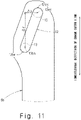
- Fig. 11 shows an amount of displacement ⁇ y that the shank outer link 6b moves away from the thigh outer link 6a in the longitudinal direction of the shank outer link 6b and an amount of displacement ⁇ x that the shank outer link 6b is drawn forward in a direction perpendicular to the longitudinal direction of the shank outer link 6b relative to the thigh outer link 6a while the knee joint is extended and the knee joint is changed from 60 degrees to 30 degrees.
- the amount of displacement ⁇ y corresponds to a difference between a center point 13bn of the thigh pin 13 when the thigh pin 13 is positioned in the flexing-side end part 12bn and a center point 13ex of the thigh pin 13 when the thigh pin 13 is positioned in the extending-side end part 12ex in the longitudinal direction of the shank outer link 6b.
- the amount of displacement ⁇ x corresponds to a difference between the center point 13bn of the thigh pin 13 when the thigh pin 13 is positioned in the flexing-side end part 12bn and the center point 13ex of the thigh pin 13 when the thigh pin 13 is positioned in the extending-side end part 12ex in the direction that is perpendicular to the longitudinal direction of the shank outer link 6b.
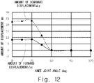
- Fig. 12 shows a graph illustrating the relation between the knee joint angle, and the amount of displacement ⁇ x and the amount of displacement ⁇ y.
- the amount of displacement ⁇ x and the amount of displacement ⁇ y increase while the knee joint angle is changed from 60 degrees to 30 degrees.
- the amount of displacement ⁇ x is 8.5 mm and the amount of displacement ⁇ y is 23.5 mm.
- the leg brace 1 is preferably attached to the left leg L of the user who is, typically, seated in a chair.
- the section of the knee joint angle in which the amount of displacement ⁇ x and the amount of displacement ⁇ y are particularly changed as shown in Fig. 12 , the amounts of displacement, and the above knee joint angle when the leg brace 1 is attached to the left leg L of the user are merely examples, and not limited to them.
- the shank pin 11 moves so as to approach the extending-side end part 10ex along the extending cam part 10d of the thigh cam 10.
- the distance between the extending cam part 10d of the thigh cam 10 and the thigh pin 13 changes little throughout the whole area of the extending cam part 10d. Therefore, as shown in Figs. 6 and 7 , while the knee joint is extended and the knee joint is changed from 30 degrees to 0 degrees, the thigh pin 13 maintains a state in which it is substantially restrained in the extending-side end part 12ex of the shank cam 12. That is, the shank outer link 6b is rotated about the thigh pin 13 by 30 degrees.
- the inner unit 7 is configured as follows.
- the thigh cam is formed in the thigh inner link 7a.
- the shank pin that is engaged with the thigh cam so that it moves along the thigh cam is formed in the shank inner link 7b.
- the shank cam is formed in the shank inner link 7b.
- the thigh pin that is engaged with the shank cam in such a way that it moves along the shank cam is formed in the thigh inner link 7a.
- the shank cam is extended rearward as it moves away from the shank attachment part 5.
- the thigh cam is formed in such a way that the shank attachment part moves away from the thigh pin as the knee joint is extended.
- the knee brace 2 includes the thigh attachment part 4 attached to the thigh L1 of the user, the shank attachment part 5 attached to the shank L2 of the user, the outer unit 6 that couples the thigh attachment part 4 to the shank attachment part 5 and is arranged on the outer (lateral) side of the left leg L (lower limb) of the user, and the inner unit 7 that couples the thigh attachment part 4 to the shank attachment part 5 and is arranged on the inner (medial) side of the left leg L of the user.
- the outer unit 6 includes the thigh outer link 6a that is extended along the thigh L1 and is fixed to the thigh L1 by the thigh attachment part 4 and the shank outer link 6b that is extended along the shank L2 and is fixed to the shank L2 by the shank attachment part 5.
- the thigh outer link 6a and the shank outer link 6b are rotatably coupled to each other on the outer side of the knee joint of the user.
- the inner unit 7 includes the thigh inner link 7a that is extended along the thigh L1 and is fixed to the thigh L1 by the thigh attachment part 4 and the shank inner link 7b that is extended along the shank L2 and is fixed to the shank L2 by the shank attachment part 5.
- the thigh inner link 7a and the shank inner link 7b are rotatably coupled to each other on the inner side of the knee joint of the user.
- the outer unit 6 is configured in such a way that the shank outer link 6b moves away from the thigh outer link 6a in the longitudinal direction of the shank outer link 6b and the shank outer link 6b is drawn forward in a direction perpendicular to the longitudinal direction of the shank outer link 6b relative to the thigh outer link 6a as the knee joint of the user is extended.
- the inner unit 7 is configured in such a way that the shank inner link 7b moves away from the thigh inner link 7a in the longitudinal direction of the shank inner link 7b and the shank inner link 7b is drawn forward in the direction perpendicular to the longitudinal direction of the shank inner link 7b relative to the thigh inner link 7a as the knee joint of the user is extended. According to the aforementioned structure, it is possible to relieve pain that occurs when a knee joint with knee joint flexion contracture is extended.
- the thigh cam 10 is formed in the thigh outer link 6a.
- the shank pin 11 that is engaged with the thigh cam 10 so that it moves along the thigh cam 10 is formed in the shank outer link 6b.
- the shank cam 12 is formed in the shank outer link 6b.
- the thigh pin 13 that is engaged with the shank cam 12 so that it moves along the shank cam 12 is formed in the thigh outer link 6a.
- the shank cam 12 is extended rearward as it moves away from the shank attachment part 5.
- the thigh cam 10 is formed in such a way that the shank attachment part 5 moves away from the thigh pin 13 as the knee joint is extended. According to the aforementioned structure, the relative movement of the shank outer link 6b with respect to the thigh outer link 6a described above is achieved with a simple structure.
- the thigh cam 10 is preferably formed in such a way that the shank attachment part 5 moves away from the thigh pin 13 while the knee joint angle is changed from 90 degrees to 0 degrees. Further specifically, the thigh cam 10 is preferably formed in such a way that the shank attachment part 5 moves away from the thigh pin 13 while the knee joint angle is changed from 60 degrees to 30 degrees.
- the amount of displacement ⁇ y in Fig. 12 is focused on. According to the aforementioned structure, the amount of displacement ⁇ y increases at the timing when pain occurs when the knee joint with knee joint flexion contracture is extended, whereby it is possible to efficiently relieve this pain.
- a leg brace 1 according to a second embodiment will be described.
- the difference between this embodiment and the above first embodiment will be mainly described and overlapping descriptions will be omitted.
- the part where the thigh outer link 6a is coupled to the shank outer link 6b according to this embodiment is different from that in the above first embodiment.
- Fig. 13 shows a state in which the shank outer link 6b is detached from the thigh outer link 6a.
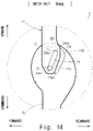
- Fig. 14 shows a state in which the shank outer link 6b is attached to the thigh outer link 6a.
- the thigh cam 20 is formed in the thigh outer link 6a.
- the shank pin 21 that is engaged with the thigh cam 20 so as to move along the thigh cam 20 is formed in the shank outer link 6b.
- the shank cam 22 is formed in the shank outer link 6b.
- the thigh pin 23 that is engaged with the shank cam 22 so as to move along the shank cam 22 is formed in the thigh outer link 6a.
- the shank outer link 6b is arranged on the inner side (on the back side of the paper) of the thigh outer link 6a.
- the shank outer link 6b may be arranged on the outer side (on the front side of the paper) of the thigh outer link 6a.
- the shank pin 21 is protruded toward the outer side and the thigh pin 13 is protruded toward the inner side.
- the thigh cam 20 is formed in the form of a slit that penetrates the thigh outer link 6a in the thickness direction of the thigh outer link 6a.
- the thigh cam 20 may be formed in the form of a groove that does not penetrate the thigh outer link 6a in the thickness direction of the thigh outer link 6a.
- the shank cam 22 is formed in the form of a groove that does not penetrate the shank outer link 6b in the thickness direction of the shank outer link 6b.
- the shank cam 22 may be formed in the form of a slit that penetrates the shank outer link 6b in the thickness direction of the shank outer link 6b.
- the thigh pin 23 is moved along the shank cam 22 and the shank pin 21 is moved along the thigh cam 20. That is, as a result of the thigh cam 20, the shank pin 21, the shank cam 22, and the thigh pin 23 working together, the outer unit 6 is configured to be flexed following flexing of the knee joint.
- the thigh cam 20 is extended forward as it moves away from the thigh attachment part 4.
- the thigh cam 20 is extended rearward as it is extended upward.
- the thigh cam 20 is inclined with respect to the longitudinal direction of the thigh cam 20.
- the thigh cam 20 is linearly extended.
- the thigh cam 20 may be curved so to be convex toward the front or may be curved so as to be convex toward the rear side.
- the thigh cam 20 includes an extending-side end part 20ex and a flexing-side end part 20bn.
- the extending-side end part 20ex is an end part where the thigh pin 23 is positioned when the knee joint is extended and the knee joint angle becomes 0 degrees.
- the flexing-side end part 20bn is an end part where the thigh pin 23 is positioned when the knee joint is flexed and the knee joint angle becomes 120 degrees. Therefore, when the knee joint is extended, the shank pin 21 moves from the flexing-side end part 20bn toward the extending-side end part 20ex. In contrast, when the knee joint is flexed, the shank pin 21 moves from the extending-side end part 20ex to the flexing-side end part 20bn.
- the thigh pin 23 is arranged above the thigh cam 20.
- the thigh pin 23 is arranged closer to the thigh attachment part 4 than to the thigh cam 20. Therefore, when the shank pin 21 is positioned in the flexing-side end part 20bn of the thigh cam 20, the shank pin 21 is made to come closest to the thigh pin 23. In contrast, when the shank pin 21 is positioned in the extending-side end part 20ex of the thigh cam 20, the shank pin 21 moves farthest away from the thigh pin 23.
- the shank cam 22 is formed in such a way that the shank attachment part 5 moves away from the thigh pin 23 as the knee joint is extended.
- the shank cam 22 is formed in such a way that it functions to move the shank attachment part 5 away from the thigh pin 23 as the knee joint is extended.
- the shank cam 22 is extended in a curved shape so as to surround the shank pin 21.
- the shank cam 22 is curved in a U-shape with an opening toward the front.
- the shank cam 22 includes an extending-side end part 22ex and a flexing-side end part 22bn.
- the extending-side end part 22ex is an end part where the thigh pin 23 is positioned when the knee joint is extended and the knee joint angle becomes 0 degrees.
- the flexing-side end part 22bn is an end part where the thigh pin 23 is positioned when the knee joint is flexed and the knee joint angle becomes 120 degrees.
- the shank cam 22 includes a flexing cam part 22a, a bending cam part 22b, and an extending cam part 22c.
- the flexing cam part 22a includes a flexing-side end part 22bn.
- the extending cam part 22c includes an extending-side end part 22ex.
- the flexing cam part 22a, the bending cam part 22b, and the extending cam part 22c are continuously formed in this order.
- the flexing cam part 22a, the bending cam part 22b, and the extending cam part 22c are continuously formed in this order from the flexing-side end part 22bn toward the extending-side end part 22ex.
- the boundary between the flexing cam part 22a and the bending cam part 22b and the boundary between the bending cam part 22b and the extending cam part 22c are shown by alternate long and two short dashes lines.
- the flexing cam part 22a is arranged in the rear of the shank pin 21 and is linearly extended.
- the flexing cam part 22a is extended rearward as it extends upward. Therefore, the flexing cam part 22a is formed in such a way that it moves away from the shank pin 21 from the side of the flexing-side end part 22bn to the side of the extending-side end part 22ex.
- the bending cam part 22b is arranged above and in the rear of the shank pin 21, and is extended in an arc shape around the center of curvature 22bc positioned above the shank pin 21. That is, the bending cam part 22b is curved so as to be convex in a direction that it moves away from the shank pin 21, in other words, to be convex upward and rearward. Therefore, the bending cam part 22b is formed in such a way that it moves away from the shank pin 21 from the side of the flexing-side end part 22bn toward the side of the extending-side end part 22ex.
- the extending cam part 22c is arranged above the shank pin 21 and is linearly extended.
- the extending cam part 22c is extended in the front-back direction. Therefore, the extending cam part 22c is made to slightly come close to the shank pin 21 from the side of the flexing-side end part 22bn to the side of the extending-side end part 22ex, and then it slightly moves away from the shank pin 21.
- the shank pin 21 is positioned in the extending-side end part 20ex of the thigh cam 20 and the thigh pin 23 is positioned in the extending-side end part 22ex of the extending cam part 22c of the shank cam 22.
- the thigh pin 23 is positioned in the extending cam part 22c and the extending cam part 22c is extended in the front-back direction. This prevents the thigh pin 23 from moving toward the bending cam part 22b of the shank cam 22 due to a ground reaction force that the diseased leg to which the knee brace 2 is attached receives when it contacts the ground. Therefore, when the diseased leg to which the knee brace 2 is attached contacts the ground, the extended state of the knee joint and the outer unit 6 is maintained.
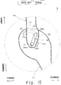
- the shank pin 21 is positioned in the extending-side end part 20ex of the thigh cam 20 and the thigh pin 23 is positioned in the bending cam part 22b of the shank cam 22.
- the shank pin 21 is slightly away from the extending-side end part 20ex of the thigh cam 20 on the side of the flexing-side end part 20bn and the thigh pin 23 is positioned in the boundary between the bending cam part 22b and the flexing cam part 22a of the shank cam 22.
- the shank pin 21 is further away from the extending-side end part 20ex of the thigh cam 20 on the side of the flexing-side end part 20bn and the thigh pin 23 is positioned in the flexing cam part 22a of the shank cam 22.
- the shank pin 21 is positioned in the flexing-side end part 20bn of the thigh cam 20 and the thigh pin 23 is positioned in the vicinity of the flexing-side end part 22bn of the flexing cam part 22a of the shank cam 22.
- the thigh pin 23 moves in such a manner that it moves away from the flexing-side end part 22bn along the flexing cam part 22a and the bending cam part 22b of the shank cam 22.
- the shank cam 22 is formed in such a way that it moves away from the shank pin 21 from the flexing cam part 22a of the shank cam 22 toward the bending cam part 22b. Therefore, while the knee joint is extended and the knee joint is changed from 120 degrees to 30 degrees as shown in Figs.
- the shank pin 21 is moved from the flexing-side end part 20bn of the thigh cam 20 to the extending-side end part 20ex.
- the shank outer link 6b is not only rotated about the shank pin 21 by 30 degrees but also the shank outer link 6b moves away from the thigh outer link 6a in the longitudinal direction of the shank outer link 6b and the shank outer link 6b is drawn forward in a direction perpendicular to the longitudinal direction of the shank outer link 6b relative to the thigh outer link 6a while the knee joint is extended and the knee joint is changed from 120 degrees to 30 degrees.
- the term "forward” means "in the direction in which the shank L2 of the left leg L is swung when the left leg L is switched from the standing leg state to the idling leg state" or "on the toe side".
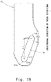
- Fig. 19 shows the amount of displacement ⁇ y that the shank outer link 6b moves away from the thigh outer link 6a in the longitudinal direction of the shank outer link 6b and the amount of displacement ⁇ x that the shank outer link 6b is drawn forward in a direction perpendicular to the longitudinal direction of the shank outer link 6b relative to the thigh outer link 6a while the knee joint is extended and the knee joint is changed from 120 degrees to 30 degrees.
- the amount of displacement ⁇ y corresponds to the difference between a center point 21bn of the shank pin 21 when the shank pin 21 is positioned in the flexing-side end part 20bn and a center point 21ex of the shank pin 21 when the shank pin 21 is positioned in the extending-side end part 20ex in the longitudinal direction of the thigh outer link 6a.
- the amount of displacement ⁇ x corresponds to the difference between the center point 21bn of the shank pin 21 when the shank pin 21 is positioned in the flexing-side end part 20bn and the center point 21ex of the shank pin 21 when the shank pin 21 is positioned in the extending-side end part 20ex in the direction that is perpendicular to the longitudinal direction of the thigh outer link 6a.
- the thigh pin 23 moves so as to approach the extending-side end part 22ex along the extending cam part 22c of the shank cam 22.
- the distance between the extending cam part 22c of the shank cam 22 and the shank pin 21 changes little throughout the whole area of the extending cam part 22c. Therefore, as shown in Figs. 14 and 15 , while the knee joint is extended and the knee joint angle is changed from 30 degrees to 0 degrees, the shank pin 21 is maintained to be substantially restrained in the extending-side end part 20ex of the thigh cam 20. That is, the shank outer link 6b is rotated about the shank pin 21 by 30 degrees.
- the inner unit 7 is configured as follows.
- the thigh cam is formed in the thigh inner link 7a.
- the shank pin that is engaged with the thigh cam so that it moves along the thigh cam is formed in the shank inner link 7b.
- the shank cam is formed in the shank inner link 7b.
- the thigh pin that is engaged with the shank cam in such a way that it moves along the shank cam is formed in the thigh inner link 7a.
- the thigh cam is extended forward as it moves away from the thigh attachment part 4.
- the shank cam is formed in such a way that the shank attachment part moves away from the thigh pin as the knee joint is extended.
- the second embodiment includes the following features.
- the thigh cam 20 is formed in the thigh outer link 6a.
- the shank pin 21 that is engaged with the thigh cam 20 so as to move along the thigh cam 20 is formed in the shank outer link 6b.
- the shank cam 22 is formed in the shank outer link 6b.
- the thigh pin 23 that is engaged with the shank cam 22 so as to move along the shank cam 22 is formed in the thigh outer link 6a.
- the thigh cam 20 is extended forward as it moves away from the thigh attachment part 4.
- the shank cam 22 is formed in such a way that the shank attachment part 5 moves away from the thigh pin 23 as the knee joint is extended. According to the aforementioned structure, the relative movement of the shank outer link 6b with respect to the thigh outer link 6a described above is achieved with a simple structure.
- the shank cam 22 is preferably formed in such a way that the shank attachment part 5 moves away from the thigh pin 23 while the knee joint angle is changed from 90 degrees to 0 degrees. Further specifically, the shank cam 22 is preferably formed in such a way that the shank attachment part 5 moves away from the thigh pin 23 while the knee joint angle is changed from 60 degrees to 30 degrees. According to the aforementioned structure, the amount of displacement ⁇ y increases at the timing when pain occurs when the knee joint with knee joint flexion contracture is extended, whereby it is possible to efficiently relieve this pain.
- the thigh cam 10 is formed in such a way that the shank attachment part 5 moves away from the thigh pin 13 in a narrow section where the knee joint is extended and the knee joint angle is changed from 60 degrees to 30 degrees.
- the shank cam 22 is formed in such a way that the shank attachment part 5 moves away from the thigh pin 23 in a wide section where the knee joint is extended and the knee joint angle is changed from 120 degrees to 30 degrees. In this manner, the shank attachment part 5 is formed in such a way that it gradually moves away from the thigh pin 23 when the knee joint is extended, whereby it is expected to reduce anxiety of users who use the leg brace 1 for the first time.
- a knee brace comprising:
Landscapes
- Health & Medical Sciences (AREA)
- Nursing (AREA)
- Orthopedic Medicine & Surgery (AREA)
- Engineering & Computer Science (AREA)
- Biomedical Technology (AREA)
- Heart & Thoracic Surgery (AREA)
- Vascular Medicine (AREA)
- Life Sciences & Earth Sciences (AREA)
- Animal Behavior & Ethology (AREA)
- General Health & Medical Sciences (AREA)
- Public Health (AREA)
- Veterinary Medicine (AREA)
- Rehabilitation Tools (AREA)
- Prostheses (AREA)
- Orthopedics, Nursing, And Contraception (AREA)
Applications Claiming Priority (1)
| Application Number | Priority Date | Filing Date | Title |
|---|---|---|---|
| JP2021021467A JP7512922B2 (ja) | 2021-02-15 | 2021-02-15 | 膝装具及び脚装具 |
Publications (1)
| Publication Number | Publication Date |
|---|---|
| EP4042984A1 true EP4042984A1 (fr) | 2022-08-17 |
Family
ID=80447780
Family Applications (1)
| Application Number | Title | Priority Date | Filing Date |
|---|---|---|---|
| EP22156040.2A Withdrawn EP4042984A1 (fr) | 2021-02-15 | 2022-02-10 | Attelle de genou et attelle de pied |
Country Status (4)
| Country | Link |
|---|---|
| US (1) | US12433777B2 (fr) |
| EP (1) | EP4042984A1 (fr) |
| JP (1) | JP7512922B2 (fr) |
| CN (1) | CN114939016B (fr) |
Families Citing this family (3)
| Publication number | Priority date | Publication date | Assignee | Title |
|---|---|---|---|---|
| US11291562B2 (en) * | 2007-02-06 | 2022-04-05 | Deka Products Limited Partnership | Arm prosthetic device |
| JP7303393B2 (ja) * | 2020-09-16 | 2023-07-04 | 株式会社アルバック | 回転式カソードユニット用の駆動ブロック |
| US20250090403A1 (en) * | 2023-09-14 | 2025-03-20 | Healing Innovations, Inc. | Articulating footplate apparatus |
Citations (5)
| Publication number | Priority date | Publication date | Assignee | Title |
|---|---|---|---|---|
| US4890607A (en) * | 1988-09-28 | 1990-01-02 | Townsend Jeffrey H | Multiaxis controlled motion knee orthosis |
| US5107824A (en) * | 1989-09-14 | 1992-04-28 | Anodyne, Inc. | Anatomically correct knee brace hinge |
| US5168865A (en) * | 1991-05-06 | 1992-12-08 | Orthopedic Systems, Inc. | Knee brace with pivot lock |
| JPH0529707U (ja) | 1991-09-26 | 1993-04-20 | 日工株式会社 | 二次製品用コンクリートホツパの案内シユート |
| US20040002674A1 (en) * | 2002-06-28 | 2004-01-01 | Generation Ii Usa, Incorporated | Anatomically designed orthopedic knee brace |
Family Cites Families (14)
| Publication number | Priority date | Publication date | Assignee | Title |
|---|---|---|---|---|
| US1390915A (en) * | 1918-05-07 | 1921-09-13 | Loth Julius Alwin | Artificial limb and the like |
| JPH0529707Y2 (fr) | 1990-07-09 | 1993-07-29 | ||
| BE1006283A3 (fr) * | 1992-10-23 | 1994-07-12 | Dumont Francoise Ghislaine | Appareil d'assistance ou de suppleance du genou. |
| AT402687B (de) * | 1996-01-24 | 1997-07-25 | Grafinger Josef | Schwenkbar miteinander verbundene schwenkbar knieführungsschienen |
| DE19605734C2 (de) * | 1996-02-16 | 2000-01-20 | Beiersdorf Ag | Kniegelenkorthese mit unterschiedlichem lateralen und medialen Orthesengelenk |
| US6010474A (en) * | 1997-06-06 | 2000-01-04 | Wycoki; Michael | Orthopedic brace for legs |
| WO2005058193A2 (fr) * | 2003-12-12 | 2005-06-30 | The Regents Of The University Of Colorado | Correction sans chirurgie d'un chargement anormal du genou |
| DE102004046743A1 (de) * | 2004-09-27 | 2006-04-06 | Gerhard Lambert | Knieorthese |
| JP2012085756A (ja) * | 2010-10-18 | 2012-05-10 | Ehime Univ | 関節装具 |
| JP5189714B2 (ja) * | 2011-01-19 | 2013-04-24 | 有限会社 愛トリノ | 膝装具及び外脚側ジョイント及び内脚側ジョイントのセット |
| JP5713388B2 (ja) * | 2011-02-10 | 2015-05-07 | 国立大学法人山梨大学 | 膝関節運動補助装置 |
| CN103932870B (zh) * | 2014-05-04 | 2016-04-13 | 浙江大学 | 仿生设计下肢康复训练外骨骼 |
| CN104873315B (zh) * | 2015-04-28 | 2018-08-14 | 繁昌县倍思生产力促进中心有限公司 | 一种免荷型膝关节矫形器 |
| JP7016075B2 (ja) * | 2017-12-25 | 2022-02-04 | 国立大学法人山梨大学 | 関節補助ユニット、歩行補助装置 |
-
2021
- 2021-02-15 JP JP2021021467A patent/JP7512922B2/ja active Active
-
2022
- 2022-02-09 US US17/668,020 patent/US12433777B2/en active Active
- 2022-02-10 CN CN202210125753.XA patent/CN114939016B/zh active Active
- 2022-02-10 EP EP22156040.2A patent/EP4042984A1/fr not_active Withdrawn
Patent Citations (5)
| Publication number | Priority date | Publication date | Assignee | Title |
|---|---|---|---|---|
| US4890607A (en) * | 1988-09-28 | 1990-01-02 | Townsend Jeffrey H | Multiaxis controlled motion knee orthosis |
| US5107824A (en) * | 1989-09-14 | 1992-04-28 | Anodyne, Inc. | Anatomically correct knee brace hinge |
| US5168865A (en) * | 1991-05-06 | 1992-12-08 | Orthopedic Systems, Inc. | Knee brace with pivot lock |
| JPH0529707U (ja) | 1991-09-26 | 1993-04-20 | 日工株式会社 | 二次製品用コンクリートホツパの案内シユート |
| US20040002674A1 (en) * | 2002-06-28 | 2004-01-01 | Generation Ii Usa, Incorporated | Anatomically designed orthopedic knee brace |
Also Published As
| Publication number | Publication date |
|---|---|
| US12433777B2 (en) | 2025-10-07 |
| JP2022123975A (ja) | 2022-08-25 |
| CN114939016B (zh) | 2025-11-11 |
| US20220257403A1 (en) | 2022-08-18 |
| CN114939016A (zh) | 2022-08-26 |
| JP7512922B2 (ja) | 2024-07-09 |
Similar Documents
| Publication | Publication Date | Title |
|---|---|---|
| EP4042984A1 (fr) | Attelle de genou et attelle de pied | |
| EP1457176B1 (fr) | Attelle de genou | |
| EP2825139B1 (fr) | Dispositif fémoro-patellaire | |
| US8376974B2 (en) | Knee orthosis swing assist mechanism | |
| EP2787937B1 (fr) | Dispositif à charnière pour le traitement de lésions de ligaments croisés postérieur | |
| US7608051B1 (en) | Osteoarthritis knee orthosis | |
| EP2948108B1 (fr) | Dispositif orthopédique doté d'un système de commande dynamique | |
| US20090182254A1 (en) | Orthopedic brace of knee joint | |
| JP2002525171A (ja) | 矢状調節部を有する膝装具 | |
| JP2021505339A (ja) | 螺旋軸を有する膝装具並びにその設計方法および製造方法 | |
| US20090105624A1 (en) | Ankle foot orthosis and method therefor | |
| US11911331B2 (en) | Leg brace and garment covering leg brace | |
| US20140336553A1 (en) | Active knee orthosis | |
| US11969372B2 (en) | Knee brace and leg brace | |
| KR102495560B1 (ko) | 고관절 발목 연동형 보행 보조 장치 | |
| CN108685670B (zh) | 关节机构 | |
| JP2010069059A (ja) | 膝装具および膝装具用ジョイント部材セット | |
| US20250288447A1 (en) | Knee orthosis with varus-valgus adjustment system | |
| WO2019044980A1 (fr) | Dispositif de support de marche | |
| US20250213414A1 (en) | Knee extension stretch device |
Legal Events
| Date | Code | Title | Description |
|---|---|---|---|
| PUAI | Public reference made under article 153(3) epc to a published international application that has entered the european phase |
Free format text: ORIGINAL CODE: 0009012 |
|
| STAA | Information on the status of an ep patent application or granted ep patent |
Free format text: STATUS: REQUEST FOR EXAMINATION WAS MADE |
|
| 17P | Request for examination filed |
Effective date: 20220223 |
|
| AK | Designated contracting states |
Kind code of ref document: A1 Designated state(s): AL AT BE BG CH CY CZ DE DK EE ES FI FR GB GR HR HU IE IS IT LI LT LU LV MC MK MT NL NO PL PT RO RS SE SI SK SM TR |
|
| STAA | Information on the status of an ep patent application or granted ep patent |
Free format text: STATUS: THE APPLICATION HAS BEEN WITHDRAWN |
|
| 18W | Application withdrawn |
Effective date: 20230710 |