EP4043052A1 - Support de seringue - Google Patents
Support de seringue Download PDFInfo
- Publication number
- EP4043052A1 EP4043052A1 EP22167274.4A EP22167274A EP4043052A1 EP 4043052 A1 EP4043052 A1 EP 4043052A1 EP 22167274 A EP22167274 A EP 22167274A EP 4043052 A1 EP4043052 A1 EP 4043052A1
- Authority
- EP
- European Patent Office
- Prior art keywords
- syringe
- syringe carrier
- carrier
- barrel
- sections
- Prior art date
- Legal status (The legal status is an assumption and is not a legal conclusion. Google has not performed a legal analysis and makes no representation as to the accuracy of the status listed.)
- Pending
Links
Images


Classifications
-
- A—HUMAN NECESSITIES
- A61—MEDICAL OR VETERINARY SCIENCE; HYGIENE
- A61M—DEVICES FOR INTRODUCING MEDIA INTO, OR ONTO, THE BODY; DEVICES FOR TRANSDUCING BODY MEDIA OR FOR TAKING MEDIA FROM THE BODY; DEVICES FOR PRODUCING OR ENDING SLEEP OR STUPOR
- A61M5/00—Devices for bringing media into the body in a subcutaneous, intra-vascular or intramuscular way; Accessories therefor, e.g. filling or cleaning devices, arm-rests
- A61M5/178—Syringes
- A61M5/24—Ampoule syringes, i.e. syringes with needle for use in combination with replaceable ampoules or carpules, e.g. automatic
-
- A—HUMAN NECESSITIES
- A61—MEDICAL OR VETERINARY SCIENCE; HYGIENE
- A61M—DEVICES FOR INTRODUCING MEDIA INTO, OR ONTO, THE BODY; DEVICES FOR TRANSDUCING BODY MEDIA OR FOR TAKING MEDIA FROM THE BODY; DEVICES FOR PRODUCING OR ENDING SLEEP OR STUPOR
- A61M5/00—Devices for bringing media into the body in a subcutaneous, intra-vascular or intramuscular way; Accessories therefor, e.g. filling or cleaning devices, arm-rests
- A61M5/178—Syringes
- A61M5/31—Details
- A61M5/32—Needles; Details of needles pertaining to their connection with syringe or hub; Accessories for bringing the needle into, or holding the needle on, the body; Devices for protection of needles
- A61M5/3205—Apparatus for removing or disposing of used needles or syringes, e.g. containers; Means for protection against accidental injuries from used needles
- A61M5/321—Means for protection against accidental injuries by used needles
-
- A—HUMAN NECESSITIES
- A61—MEDICAL OR VETERINARY SCIENCE; HYGIENE
- A61M—DEVICES FOR INTRODUCING MEDIA INTO, OR ONTO, THE BODY; DEVICES FOR TRANSDUCING BODY MEDIA OR FOR TAKING MEDIA FROM THE BODY; DEVICES FOR PRODUCING OR ENDING SLEEP OR STUPOR
- A61M5/00—Devices for bringing media into the body in a subcutaneous, intra-vascular or intramuscular way; Accessories therefor, e.g. filling or cleaning devices, arm-rests
- A61M5/178—Syringes
- A61M5/24—Ampoule syringes, i.e. syringes with needle for use in combination with replaceable ampoules or carpules, e.g. automatic
- A61M2005/2403—Ampoule inserted into the ampoule holder
- A61M2005/2407—Ampoule inserted into the ampoule holder from the rear
-
- A—HUMAN NECESSITIES
- A61—MEDICAL OR VETERINARY SCIENCE; HYGIENE
- A61M—DEVICES FOR INTRODUCING MEDIA INTO, OR ONTO, THE BODY; DEVICES FOR TRANSDUCING BODY MEDIA OR FOR TAKING MEDIA FROM THE BODY; DEVICES FOR PRODUCING OR ENDING SLEEP OR STUPOR
- A61M5/00—Devices for bringing media into the body in a subcutaneous, intra-vascular or intramuscular way; Accessories therefor, e.g. filling or cleaning devices, arm-rests
- A61M5/178—Syringes
- A61M5/24—Ampoule syringes, i.e. syringes with needle for use in combination with replaceable ampoules or carpules, e.g. automatic
- A61M2005/2403—Ampoule inserted into the ampoule holder
- A61M2005/2414—Ampoule inserted into the ampoule holder from the side
-
- A—HUMAN NECESSITIES
- A61—MEDICAL OR VETERINARY SCIENCE; HYGIENE
- A61M—DEVICES FOR INTRODUCING MEDIA INTO, OR ONTO, THE BODY; DEVICES FOR TRANSDUCING BODY MEDIA OR FOR TAKING MEDIA FROM THE BODY; DEVICES FOR PRODUCING OR ENDING SLEEP OR STUPOR
- A61M5/00—Devices for bringing media into the body in a subcutaneous, intra-vascular or intramuscular way; Accessories therefor, e.g. filling or cleaning devices, arm-rests
- A61M5/178—Syringes
- A61M5/24—Ampoule syringes, i.e. syringes with needle for use in combination with replaceable ampoules or carpules, e.g. automatic
- A61M2005/2433—Ampoule fixed to ampoule holder
- A61M2005/2437—Ampoule fixed to ampoule holder by clamping means
-
- A—HUMAN NECESSITIES
- A61—MEDICAL OR VETERINARY SCIENCE; HYGIENE
- A61M—DEVICES FOR INTRODUCING MEDIA INTO, OR ONTO, THE BODY; DEVICES FOR TRANSDUCING BODY MEDIA OR FOR TAKING MEDIA FROM THE BODY; DEVICES FOR PRODUCING OR ENDING SLEEP OR STUPOR
- A61M5/00—Devices for bringing media into the body in a subcutaneous, intra-vascular or intramuscular way; Accessories therefor, e.g. filling or cleaning devices, arm-rests
- A61M5/178—Syringes
- A61M5/31—Details
- A61M5/32—Needles; Details of needles pertaining to their connection with syringe or hub; Accessories for bringing the needle into, or holding the needle on, the body; Devices for protection of needles
- A61M5/3202—Devices for protection of the needle before use, e.g. caps
Definitions
- the invention relates to syringe carrier.
- a pre-filled syringe is housed in a carrier which is axially movable to achieve needle penetration in an injection site and, optionally, needle withdrawal.
- a conventional carrier provides shoulders that are adapted to engage a neck on the syringe and prevent the syringe from disengaging the carrier. Because syringes are generally supplied with rigid needle shields covering the needle and those needle shields have a diameter greater than a diameter between the shoulders, a separate assembly step is required - inserting the syringe in the carrier and then attaching the rigid needle shield to the needle. Accordingly, there is a need for a syringe carrier which does not require this separate assembly step.
- a syringe carrier comprises a body adapted to receive a barrel of a syringe.
- the body includes two sections having distal ends with shoulder sections adapted to engage a circumferential gap between the barrel of the syringe and a needle shield covering a needle of the syringe.
- the sections are resiliently coupled to a collar on a proximal end of the body.
- the shoulder sections deflect when engaged by the needle shield and return to a non-deflected position when disengaged by the needle shield to engage the circumferential gap between the barrel of the syringe and the needle shield.
- the sections are resiliently coupled to a collar on a distal end of the body.
- the sections deflect when engaged by the needle shield and return to a non-deflected position when disengaged by the needle shield to engage a finger flange of the syringe.
- the body includes resilient arms having additional shoulder sections adapted to engage the circumferential gap between the barrel of the syringe and a needle shield covering a needle of the syringe. The arms deflect when engaged by the needle shield and return to a non-deflected position when disengaged by the needle shield to engage the circumferential gap between the barrel of the syringe and a needle shield.
- the sections are coupled via at least one hinge and are movable between an open position and a closed position.
- a first section includes a pin adapted to engage a hole on a second section to secure the sections in the closed position.
- the sections are coupled via at least one clip and are movable between an open position and a closed position.
- the at least one clip includes a hook on a first section adapted to engage an eye on a second section to secure the sections in the closed position.
- the sections include doors hingedly coupled to the body and additional shoulder sections are formed on distal ends of the doors.
- the shoulder sections include proximally-facing contoured surfaces to accommodate a proximal portion of a neck of the syringe and distally-facing planar surfaces to abut the needle shield.
- the body includes one or more viewing windows.
- the body includes a retainer element adapted to provide an abutment surface to prevent the syringe from disengaging the syringe carrier in a proximal direction.
- the syringe 2 comprises a barrel 2.1 and a neck 2.2 which has a smaller diameter than the barrel 2.1.
- a needle 3 is mounted to the neck 2.2 and a rigid needle shield (RNS) 4 is removably arranged on the needle 3.
- RNS rigid needle shield
- a portion of the RNS may cover a portion of the neck 2.2, leaving a circumferential gap between the barrel 2.1 and the RNS 4.
- the RNS 4 has a diameter substantially equal to the diameter of the barrel 2.1.
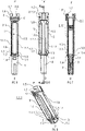
- Figures 1-4 show a first exemplary embodiment of a syringe carrier 1 according to the present in invention.
- Figure 1 is a top view of the syringe carrier 1 for supporting a syringe 2.
- Figure 2 is a lateral view of the syringe carrier of figure 1.
- Figure 3 is a longitudinal section of the syringe carrier of figure 1 in the section plane A-A.
- Figure 4 is a perspective view of the syringe carrier of figure 1 without the syringe 2.
- the syringe carrier 1 comprises an elongate body 1.1 arranged to receive the barrel 2.1.
- the body 1.1 has a cylindrical shape with an internal diameter corresponding to the diameter of the barrel 2.1.
- the body 1.1 comprises a collar 1.2 at a proximal end dimensioned to allow axial insertion of the syringe 2 into the syringe carrier 1 in a distal direction D.
- Resilient sections 1.1.1 extend distally from the collar 1.2.
- Distal ends of the sections 1.1.1 include shoulder sections 1.4 shaped as portions of a circle arranged in a transverse plane with respect to a longitudinal axis of the carrier 1.
- the shoulder sections include facing surfaces 6.
- the facing surfaces 6 When the sections 1.1.1 are in a non-deflected position, the facing surfaces 6 may abut each other, and the shoulder sections 1.4 form a circular shoulder (because the facing surfaces 6 abut each other) adapted to engage the circumferential gap between the barrel 2.1 and the RNS 4.
- the syringe 2, with RNS 4 attached to the needle 3, may be loaded into the syringe carrier 1 by sliding the syringe 2 in the distal direction D into the syringe carrier 2.
- RNS 4 abuts the shoulder sections 1.4
- additional axial force may be applied to cause the arms 1.3 to deflect radially.
- the sections 1.1.1 may return to the non-deflected position, and the shoulder sections 1.4 may engage the circumferential gap between the barrel 2.1 and the RNS 4 and prevent the syringe 2 from moving in the distal direction D relative to the syringe carrier 1.
- the proximal end 1.5 of the body 1.1 may be arranged to receive a finger flange 2.3 of the syringe 2.
- the shoulder sections 1.4 may include proximally-facing contoured surfaces to accommodate a proximal portion of the neck 2.2 of the syringe 2 and distally-facing planar surfaces to abut the RNS 4.
- viewing windows 5 may be arranged in the body 1.1 for allowing visual access to the barrel 2.1 of the syringe 2 when the syringe 2 is in the syringe carrier 2.
- the windows 5 are formed when cut-outs in the arms 1.3 are substantially contiguous when the arms 1.3 are in the non-deflected position (as shown in Figure 1 ).
- a projection 1.6 may be formed around each cut-out, and when the sections 1.1.1 are in the non-deflected position, the projections 1.6 may form an outline for the window 5.
- the windows 5 may be formed in the sections 1.1.1.
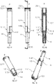
- Figures 5-8 show a second exemplary embodiment of a syringe carrier 1 according to the present invention.
- Figure 6 is a lateral view of the syringe carrier 1 of figure 5.
- Figure 7 is a longitudinal section of the syringe carrier 1 of figure 5 in the section plane A-A.
- Figure 8 is a perspective view of the syringe carrier of figure 5 without the syringe 2.
- the syringe carrier 1 comprises an elongate body 1.1 arranged to receive the barrel 2.1.
- the body 1.1 is comprised of two resilient sections 1.1.1 which, when together, have a cylindrical shape with an internal diameter corresponding to the diameter of the barrel 2.1.
- Distal ends of the sections 1.1.1 of the body 1.1 comprise part of a collar 1.2 dimensioned to allow axial insertion of the syringe 2 into the syringe carrier 1.
- Resilient arms 1.3 are formed in the body 1.1.
- Distal ends of the arms 1.3 include shoulder sections 1.4 shaped as portions of a circle arranged in a transverse plane with respect to a longitudinal axis of the carrier 1.
- the shoulder sections include facing surfaces 6.
- the facing surfaces 6 may abut the distal ends of the sections 1.1.1 of the body 1.1 to form a circular shoulder adapted to engage the circumferential gap between the barrel 2.1 and the RNS 4.
- the syringe 2, with RNS 4 attached to the needle 3, may be loaded into the syringe carrier 1 by sliding the syringe 2 in the distal direction D into the syringe carrier 2.
- the sections 1.1.1 may deflect radially.
- the sections 1.1.1 may return to the non-deflected position.
- the arms 1.3 may deflect until the RNS 4 bypasses the shoulder sections 1.4.
- the arms 1.3 may return to the non-deflected position, and the shoulder sections 1.4 and the collar 1.2 may engage the circumferential gap between the barrel 2.1 and the RNS 4 and prevent the syringe 2 from moving in the distal direction D relative to the syringe carrier 1.
- the proximal end 1.5 of the body 1.1 may be arranged to receive a finger flange 2.3 of the syringe 2.
- the proximal end 1.5 may also include a retainer element 1.7 which is adapted to provide an abutment surface to prevent the syringe 2 from disengaging the syringe carrier 1 in the proximal direction D.
- the shoulder sections 1.4 may include proximally-facing contoured surfaces to accommodate a proximal portion of the neck 2.2 of the syringe 2 and distally-facing planar surfaces to abut the RNS 4.
- viewing windows 5 may be arranged in the body 1.1 for allowing visual access to the barrel 2.1 of the syringe 2 when the syringe 2 is in the syringe carrier 2.
- the windows 5 are formed when cut-outs in the sections 1.1.1 are substantially contiguous when the sections 1.1.1 are in the non-deflected position (as shown in Figure 5 ).
- a projection 1.6 may be formed around each cut-out, and when the sections 1.1.1 are in the non-deflected position, the projections 1.6 may form an outline for the window 5.
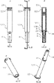
- Figures 9-13 show a third exemplary embodiment of a syringe carrier 1 according to the present invention.
- Figure 9 is a top view of a third embodiment of a syringe carrier 1 for supporting a syringe 2.
- Figure 10 is a lateral view of the syringe carrier 1 of figure 9.
- Figure 11 is a longitudinal section of the syringe carrier 1 of figure 9 in the section plane A-A.
- Figure 12 is a perspective view of the syringe carrier of figure 9 without the syringe 2.
- Figure 13 is another perspective view of the syringe carrier of figure 9 .
- the syringe carrier 1 comprises an elongate body 1.1 arranged to receive the barrel 2.1.
- the body 1.1 is comprised of two sections 1.1.1 which, when together, have a cylindrical shape with an internal diameter corresponding to the diameter of the barrel 2.1.
- the sections 1.1.1 may be coupled by a side hinge which allows the section 1.1.1 to rotate relative to each other sufficient to receive the syringe 2.
- Proximal and distal ends of the sections 1.1.1 include shoulder sections 1.4 shaped as portions of a circle arranged in a transverse plane with respect to a longitudinal axis of the carrier 1.
- the shoulder sections include facing surfaces 6.
- the facing surfaces 6 When the sections 1.1.1 are in a closed position, the facing surfaces 6 may abut each other so that the shoulder sections 1.4 form circular shoulders adapted to proximally abut a finger flange 2.3 on the syringe 2 and to distally engage the circumferential gap between the barrel 2.1 and the RNS 4.
- the facing surfaces 6 of one section 1.1.1 may include holes 1.10 and the facing surfaces 6 of the other section 1.1.1 may include pins 1.11 adapted to engage (e.g., frictionally, snap-fit, etc.) the holes 1.10 to secure the sections 1.1.1 in the closed position.
- the syringe 2, with RNS 4 attached to the needle 3, may be loaded into the syringe carrier 1 by opening the sections 1.1.1 about the hinge and placing the syringe 2 in the syringe carrier 2.
- the sections 1.1.1 are closed, the pins 1.11 engage the holes 1.10, and the proximal shoulder sections 1.4 form circular shoulders adapted to proximally abut a finger flange 2.3 on the syringe 2 and the distal shoulder section s1.4 to distally engage the circumferential gap between the barrel 2.1 and the RNS 4.
- the syringe 2 is prevented from moving axially relative to the syringe carrier 1.
- the proximal end 1.5 may include a retainer element 1.7 which is adapted to provide an abutment surface to prevent the syringe 2 from disengaging the syringe carrier 1 in the proximal direction D.
- the shoulder sections 1.4 may include proximally-facing contoured surfaces to accommodate a proximal portion of the neck 2.2 of the syringe 2 and distally-facing planar surfaces to abut the RNS 4.
- viewing windows 5 may be arranged in the body 1.1 for allowing visual access to the barrel 2.1 of the syringe 2 when the syringe 2 is in the syringe carrier 2.
- the windows 5 are formed when cut-outs in the sections 1.1.1 are substantially contiguous when the sections 1.1.1 are in the closed position.
- a projection 1.6 may be formed around each cut-out, and when the sections 1.1.1 are in the non-deflected position, the projections 1.6 may form an outline for the window 5.
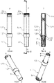
- Figures 14-18 show a fourth exemplary embodiment of a syringe carrier 1 according to the present invention.
- Figure 14 is a top view of a fourth embodiment of a syringe carrier 1 for supporting a syringe 2.
- Figure 15 is a lateral view of the syringe carrier 1 of figure 14.
- Figure 16 is a longitudinal section of the syringe carrier 1 of figure 14 in the section plane A-A.
- Figure 17 is a perspective view of the syringe carrier of figure 14 without the syringe 2.
- Figure 18 is another perspective view of the syringe carrier of figure 14 .
- the syringe carrier 1 comprises an elongate body 1.1 arranged to receive the barrel 2.1.
- the body 1.1 has a cylindrical shape with an internal diameter corresponding to the diameter of the barrel 2.1.
- a distal end of the body 1.1 includes a shoulder sections 1.4 shaped as a portion of a circle arranged in a transverse plane with respect to a longitudinal axis of the carrier 1, and at least one door 1.12 hingedly coupled to the body 1.1 and including a shoulder section 1.4.
- a hinge 1.9 coupling the door 1.12 to the body 1.1 may be provided on an axis parallel to the longitudinal axis of the syringe carrier 1 or on an axis transverse to the longitudinal axis of the syringe carrier 1.
- the shoulder section 1.4 includes facing surfaces 6 which abut facing surfaces 6 of the door 1.12 when the door 1.12 is in a closed position (as shown in Figure 14 ). When the door 1.12 is in the closed position, the facing surfaces 6 may abut each other so that the shoulder sections 1.4 on the body 1.1 and the door 1.12 to form a circular shoulder adapted to engage the circumferential gap between the barrel 2.1 and the RNS 4.
- the facing surfaces 6 of the door 1.12 may include holes 1.10 and the facing surfaces 6 of the body 1.1 may include pins 1.11 (or vice-versa) adapted to engage (e.g., frictionally, snap-fit, etc.) the holes 1.10 to secure the door 1.12 in the closed position.
- the syringe 2, with RNS 4 attached to the needle 3, may be loaded into the syringe carrier 1 by opening the door 1.12 and sliding the syringe 2 into the syringe carrier 1.
- the door 1.12 may be closed to engage the gap and prevent the syringe 2 from moving axially relative to the syringe carrier 1.
- the shoulder sections 1.4 may include proximally-facing contoured surfaces to accommodate a proximal portion of the neck 2.2 of the syringe 2 and distally-facing planar surfaces to abut the RNS 4.
- viewing windows may be arranged in the body 1.1 for allowing visual access to the barrel 2.1 of the syringe 2 when the syringe 2 is in the syringe carrier 2.
- the windows are formed as cut-outs.
- Figures 19-23 show a fifth exemplary embodiment of a syringe carrier 1 according to the present invention.
- Figure 19 is a top view of a fifth embodiment of a syringe carrier 1 for supporting a syringe 2.
- Figure 20 is a lateral view of the syringe carrier 1 of figure 19.
- Figure 21 is a longitudinal section of the syringe carrier 1 of figure 19 in the section plane A-A.
- Figure 22 is a perspective view of the syringe carrier of figure 19 without the syringe 2.
- Figure 23 is another perspective view of the syringe carrier of figure 19 .
- the syringe carrier 1 comprises an elongate body 1.1 arranged to receive the barrel 2.1.
- the body 1.1 is comprised of two sections 1.1.1 which, when together, have a cylindrical shape with an internal diameter corresponding to the diameter of the barrel 2.1.
- the sections 1.1.1 may be coupled together by clips.
- a clip may comprise a eye 1.14 on a first section adapted to engage a hook 1.13 on a second section.
- the eye 1.14 may have a cross-section substantially equal to the cross-section of the hook 1.13 such that the eye 1.14 and hook 1.13 engage in a snap-fit.
- Distal ends of the sections 1.1.1 include shoulder sections 1.4 shaped as portions of a circle arranged in a transverse plane with respect to a longitudinal axis of the carrier 1.
- the shoulder sections include facing surfaces 6. When the sections 1.1.1 are in a closed position, the facing surfaces 6 may abut each other so that the shoulder sections 1.4 form circular shoulders adapted engage the circumferential gap between the barrel 2.1 and the RNS 4.
- the sections 1.1.1 may be hingedly connected.
- the syringe 2, with RNS 4 attached to the needle 3, may be loaded into the syringe carrier 1 by opening the sections 1.1.1 and placing the syringe 2 in the syringe carrier 2.
- the sections 1.1.1 are closed, the eyes 1.14 engage the hooks 1.13 and the shoulder sections 1.4 engage the circumferential gap between the barrel 2.1 and the RNS 4.
- the syringe 2 is prevented from moving axially relative to the syringe carrier 1.
- the proximal end may include a retainer element which is adapted to provide an abutment surface to prevent the syringe 2 from disengaging the syringe carrier 1 in the proximal direction D.
- the shoulder sections 1.4 may include proximally-facing contoured surfaces to accommodate a proximal portion of the neck 2.2 of the syringe 2 and distally-facing planar surfaces to abut the RNS 4.
- viewing windows may be arranged in the body 1.1 for allowing visual access to the barrel 2.1 of the syringe 2 when the syringe 2 is in the syringe carrier 2.
- Figures 24-28 show a sixth exemplary embodiment of a syringe carrier 1 according to the present invention.
- Figure 24 is a top view of a sixth embodiment of a syringe carrier 1 for supporting a syringe 2.
- Figure 25 is a lateral view of the syringe carrier 1 of figure 24.
- Figure 26 is a longitudinal section of the syringe carrier 1 of figure 24 in the section plane A-A.
- Figure 27 is a perspective view of the syringe carrier of figure 24 without the syringe 2.
- Figure 28 is another perspective view of the syringe carrier of figure 24 .
- the syringe carrier 1 comprises an elongate body 1.1 arranged to receive the barrel 2.1.
- the body 1.1 has a partially cylindrical shape with an internal diameter corresponding to the diameter of the barrel 2.1.
- the body 1.1 may include a longitudinal slot (e.g., a cut-out) which is adapted to snap over the barrel 2.1 of the syringe 2.
- Proximal and distal ends of the body 1.1 include clamps 1.15, 1.16 which are adapted to retain the syringe 2 when in the syringe carrier 1.
- the distal end of the body 1 further includes shoulder sections 1.4 shaped as a portion of a circle arranged in a transverse plane with respect to a longitudinal axis of the carrier 1.
- the shoulder sections 14 form circular shoulders adapted to engage the circumferential gap between the barrel 2.1 and the RNS 4.
- the syringe 2, with RNS 4 attached to the needle 3, may be loaded into the syringe carrier 1 by pressing the barrel 2.1 against the clamps 1.15, 1.16, causing the clamps 1.15, 1.16 to deflect and widen the longitudinal slot in the body 1.1.
- the clamps 1.15, 1.16 return to their non-deflected position and retain the syringe 2 in the syringe carrier 1.
- the shoulder sections 1.4 engage the circumferential gap between the barrel 2.1 and the RNS 4.
- the proximal end may include a retainer element which is adapted to provide an abutment surface to prevent the syringe 2 from disengaging the syringe carrier 1 in the proximal direction D.
- the shoulder sections 1.4 may include proximally-facing contoured surfaces to accommodate a proximal portion of the neck 2.2 of the syringe 2 and distally-facing planar surfaces to abut the RNS 4.
- a viewing window may be arranged in the body 1.1 for allowing visual access to the barrel 2.1 of the syringe 2 when the syringe 2 is in the syringe carrier 2.
- Figures 29-33 show a seventh exemplary embodiment of a syringe carrier 1 according to the present invention.
- Figure 29 is a top view of a seventh embodiment of a syringe carrier 1 for supporting a syringe 2.
- Figure 30 is a lateral view of the syringe carrier 1 of figure 29.
- Figure 31 is a longitudinal section of the syringe carrier 1 of figure 29 in the section plane A-A.
- Figure 32 is a perspective view of the syringe carrier of figure 29 without the syringe 2.
- Figure 33 is another perspective view of the syringe carrier of figure 29 .
- the syringe carrier 1 comprises an elongate body 1.1 arranged to receive the barrel 2.1.
- the body 1.1 has a partially cylindrical shape with an internal diameter corresponding to the diameter of the barrel 2.1.
- the body 1.1 includes a collar 1.2 at its proximal end and may include a longitudinal slot (e.g., a cut-out) formed in the body 1.1 distally of the collar 1.2 which is adapted to snap over the barrel 2.1 of the syringe 2.
- a pair of groove hinges 1.17 may be formed in the body 1.1 adjacent a proximal end of the slot.
- the distal end of the body 1 includes shoulder sections 1.4 shaped as a portion of a circle arranged in a transverse plane with respect to a longitudinal axis of the carrier 1.
- the shoulder sections 14 form circular shoulders adapted to engage the circumferential gap between the barrel 2.1 and the RNS 4.
- the syringe 2, with RNS 4 attached to the needle 3, may be loaded into the syringe carrier 1 by sliding the syringe 2 through the collar 1.2 in the distal direction D.
- the body 1.1 may radially deflect (e.g., rotate) about the groove hinges 1.17.
- the RNS 4 bypasses the shoulder sections 1.4, the body 1.1 may return to its non-deflected position and retain the syringe 2 in the syringe carrier 1.
- the shoulder sections 1.4 engage the circumferential gap between the barrel 2.1 and the RNS 4.
- the syringe 2 is prevented from moving axially relative to the syringe carrier 1.
- the proximal end may include a retainer element which is adapted to provide an abutment surface to prevent the syringe 2 from disengaging the syringe carrier 1 in the proximal direction D.
- the shoulder sections 1.4 may include proximally-facing contoured surfaces to accommodate a proximal portion of the neck 2.2 of the syringe 2 and distally-facing planar surfaces to abut the RNS 4.
- a viewing window may be arranged in the body 1.1 for allowing visual access to the barrel 2.1 of the syringe 2 when the syringe 2 is in the syringe carrier 2.
- Figures 34-38 show an eighth exemplary embodiment of a syringe carrier 1 according to the present invention.
- Figure 34 is a top view of an eighth embodiment of a syringe carrier 1 for supporting a syringe 2.
- Figure 35 is a lateral view of the syringe carrier 1 of figure 34.
- Figure 36 is a longitudinal section of the syringe carrier 1 of figure 34 in the section plane A-A.
- Figure 37 is a perspective view of the syringe carrier of figure 34 without the syringe 2.
- Figure 38 is another perspective view of the syringe carrier of figure 34 .
- the syringe carrier 1 comprises an elongate body 1.1 arranged to receive the barrel 2.1.
- the body 1.1 has a cylindrical shape with an annular groove 1.19 adjacent its distal end which is adapted to engage a circlip 8.
- the circlip 8 may engage the circumferential gap between the barrel 1.2 and the RNS 4.
- the syringe 2, with RNS 4 attached to the needle 3 and the circlip 8 attached to the syringe 2, may be loaded into the syringe carrier 1 by sliding the syringe 2 into the syringe carrier 1 in the distal direction D.
- an outer diameter of the circlip 8 may be substantially equal to a diameter of the body 1.1.
- the circlip 8 may then expand to the non-deflected position and retain the syringe 2 in an axial position relative to the syringe carrier 1. That is, the circlip 8 may engage the annular groove 1.19 and the circumferential gap between the barrel 2.1 and the RNS 4. Thus, the syringe 2 is prevented from moving axially relative to the syringe carrier 1.
- the proximal end may include a retainer element which is adapted to provide an abutment surface to prevent the syringe 2 from disengaging the syringe carrier 1 in the proximal direction D.
- the shoulder sections 1.4 may include proximally-facing contoured surfaces to accommodate a proximal portion of the neck 2.2 of the syringe 2 and distally-facing planar surfaces to abut the RNS 4.
- a viewing window may be arranged in the body 1.1 for allowing visual access to the barrel 2.1 of the syringe 2 when the syringe 2 is in the syringe carrier 2.
- Figures 39-43 show a ninth exemplary embodiment of a syringe carrier 1 according to the present invention.
- Figure 39 is a top view of a ninth embodiment of a syringe carrier 1 for supporting a syringe 2.
- Figure 40 is a lateral view of the syringe carrier 1 of figure 39.
- Figure 41 is a longitudinal section of the syringe carrier 1 of figure 39 in the section plane A-A.
- Figure 42 is a perspective view of the syringe carrier of figure 39 without the syringe 2.
- Figure 43 is another perspective view of the syringe carrier of figure 39 .
- the syringe carrier 1 comprises an elongate body 1.1 arranged to receive the barrel 2.1.
- the body 1.1 has a cylindrical shape with an annular groove 1.19 having at least one aperture 1.20 adjacent its distal end which is adapted to engage a circlip 8.
- the syringe 2, with RNS 4 attached to the needle 3, may be loaded into the syringe carrier 1 by sliding the syringe 2 into the syringe carrier 1 in the distal direction D.
- the circlip 8 may be coupled to the body 1.1 and engage the apertures 1.20. By extending inwardly through the apertures, the circlip 8 may be coupled to the outside of the body 1.1 but engage the circumferential gap between the barrel 2.1 and the RNS 4.
- the engagement between the circlip 8 and the apertures 1.20 prevents the circlip 8 from translating relative to the body 1.1, and the engagement between the circlip 8 and the circumferential gap prevents the syringe 2 from moving axially relative to the syringe carrier 1.
- the proximal end may include a retainer element which is adapted to provide an abutment surface to prevent the syringe 2 from disengaging the syringe carrier 1 in the proximal direction D.
- the shoulder sections 1.4 may include proximally-facing contoured surfaces to accommodate a proximal portion of the neck 2.2 of the syringe 2 and distally-facing planar surfaces to abut the RNS 4.
- a viewing window may be arranged in the body 1.1 for allowing visual access to the barrel 2.1 of the syringe 2 when the syringe 2 is in the syringe carrier 2.
- Figures 44-48 show a tenth exemplary embodiment of a syringe carrier 1 and a tool 9 for inserting a syringe 2 into the syringe carrier 1 according to the present invention.
- the syringe carrier 1 comprises an elongate body 1.1 arranged to receive the barrel 2.1.
- the body 1.1 has an enlarged portion 1.21 on its distal end.
- the body 1.1 has cylindrical shape with a first diameter and the enlarged portion 1.21 has a second diameter, larger than the first diameter.
- the enlarged portion 1.21 has one or more resilient barbs 1.22 extending toward a longitudinal axis of the body 1.1 and angled toward a proximal end of the body 1.1.
- the syringe 2, with RNS 4 attached to the needle 3, may be loaded into the syringe carrier 1 by inserting the tool 9 into the enlarged portion 1.21 of the syringe carrier 1.
- the tool 9 may be a cylinder having an open end adapted to receive the RNS 4.
- the tool 9 may have a third diameter substantially equal to the second diameter.
- the tool 9 engages and deflects the resilient barbs 1.22.
- the RNS 4 can pass the barbs 1.22 in the distal direction D and extend from a distal opening of the body 1.1.
- the tool 9 may be removed and the barbs 1.22 may engage the circumferential gap between the barrel 2.1 and the RNS 4 to prevent the syringe 2 from moving axially relative to the syringe carrier 1.
- the proximal end may include a retainer element which is adapted to provide an abutment surface to prevent the syringe 2 from disengaging the syringe carrier 1 in the proximal direction D.
- the barbs 1.22 may include proximally-facing contoured surfaces to accommodate a proximal portion of the neck 2.2 of the syringe 2 and distally-facing planar surfaces to abut the RNS 4.
- a viewing window may be arranged in the body 1.1 for allowing visual access to the barrel 2.1 of the syringe 2 when the syringe 2 is in the syringe carrier 2.
Landscapes
- Health & Medical Sciences (AREA)
- Engineering & Computer Science (AREA)
- Hematology (AREA)
- Anesthesiology (AREA)
- Biomedical Technology (AREA)
- Heart & Thoracic Surgery (AREA)
- Vascular Medicine (AREA)
- Life Sciences & Earth Sciences (AREA)
- Animal Behavior & Ethology (AREA)
- General Health & Medical Sciences (AREA)
- Public Health (AREA)
- Veterinary Medicine (AREA)
- Environmental & Geological Engineering (AREA)
- Infusion, Injection, And Reservoir Apparatuses (AREA)
Applications Claiming Priority (4)
| Application Number | Priority Date | Filing Date | Title |
|---|---|---|---|
| EP11192585.5A EP2601992A1 (fr) | 2011-12-08 | 2011-12-08 | Support de seringue |
| EP16195290.8A EP3153196B1 (fr) | 2011-12-08 | 2012-12-05 | Support de seringue |
| PCT/EP2012/074466 WO2013083613A1 (fr) | 2011-12-08 | 2012-12-05 | Support de seringue |
| EP12794996.4A EP2788055B1 (fr) | 2011-12-08 | 2012-12-05 | Support de seringue |
Related Parent Applications (3)
| Application Number | Title | Priority Date | Filing Date |
|---|---|---|---|
| EP16195290.8A Division EP3153196B1 (fr) | 2011-12-08 | 2012-12-05 | Support de seringue |
| EP16195290.8A Division-Into EP3153196B1 (fr) | 2011-12-08 | 2012-12-05 | Support de seringue |
| EP12794996.4A Division EP2788055B1 (fr) | 2011-12-08 | 2012-12-05 | Support de seringue |
Publications (1)
| Publication Number | Publication Date |
|---|---|
| EP4043052A1 true EP4043052A1 (fr) | 2022-08-17 |
Family
ID=47278865
Family Applications (6)
| Application Number | Title | Priority Date | Filing Date |
|---|---|---|---|
| EP11192585.5A Ceased EP2601992A1 (fr) | 2011-12-08 | 2011-12-08 | Support de seringue |
| EP22167274.4A Pending EP4043052A1 (fr) | 2011-12-08 | 2012-12-05 | Support de seringue |
| EP16195292.4A Active EP3153197B1 (fr) | 2011-12-08 | 2012-12-05 | Support de seringue |
| EP16195290.8A Active EP3153196B1 (fr) | 2011-12-08 | 2012-12-05 | Support de seringue |
| EP12794996.4A Active EP2788055B1 (fr) | 2011-12-08 | 2012-12-05 | Support de seringue |
| EP22167268.6A Pending EP4043051A1 (fr) | 2011-12-08 | 2012-12-05 | Support de seringue |
Family Applications Before (1)
| Application Number | Title | Priority Date | Filing Date |
|---|---|---|---|
| EP11192585.5A Ceased EP2601992A1 (fr) | 2011-12-08 | 2011-12-08 | Support de seringue |
Family Applications After (4)
| Application Number | Title | Priority Date | Filing Date |
|---|---|---|---|
| EP16195292.4A Active EP3153197B1 (fr) | 2011-12-08 | 2012-12-05 | Support de seringue |
| EP16195290.8A Active EP3153196B1 (fr) | 2011-12-08 | 2012-12-05 | Support de seringue |
| EP12794996.4A Active EP2788055B1 (fr) | 2011-12-08 | 2012-12-05 | Support de seringue |
| EP22167268.6A Pending EP4043051A1 (fr) | 2011-12-08 | 2012-12-05 | Support de seringue |
Country Status (14)
| Country | Link |
|---|---|
| US (17) | US10434258B2 (fr) |
| EP (6) | EP2601992A1 (fr) |
| JP (1) | JP6096206B2 (fr) |
| KR (1) | KR20140105525A (fr) |
| AU (1) | AU2012347359B2 (fr) |
| BR (1) | BR112014013780A2 (fr) |
| DK (3) | DK3153197T3 (fr) |
| ES (1) | ES2623256T3 (fr) |
| HU (1) | HUE032673T2 (fr) |
| IL (1) | IL232989A0 (fr) |
| MX (1) | MX2014006847A (fr) |
| PL (1) | PL2788055T3 (fr) |
| RU (1) | RU2618900C2 (fr) |
| WO (1) | WO2013083613A1 (fr) |
Families Citing this family (30)
| Publication number | Priority date | Publication date | Assignee | Title |
|---|---|---|---|---|
| US20070202186A1 (en) | 2006-02-22 | 2007-08-30 | Iscience Interventional Corporation | Apparatus and formulations for suprachoroidal drug delivery |
| US8197435B2 (en) | 2006-05-02 | 2012-06-12 | Emory University | Methods and devices for drug delivery to ocular tissue using microneedle |
| JP5996544B2 (ja) | 2010-10-15 | 2016-09-21 | クリアサイド・バイオメディカル・インコーポレーテッドClearside Biomedical Incorporated | 眼球アクセス用装置 |
| CN103491998B (zh) * | 2011-01-24 | 2015-11-25 | 爱康医学农业合作协会有限公司 | 注射器 |
| EP2601989A1 (fr) * | 2011-12-08 | 2013-06-12 | Sanofi-Aventis Deutschland GmbH | Support de seringue |
| EP2601992A1 (fr) | 2011-12-08 | 2013-06-12 | Sanofi-Aventis Deutschland GmbH | Support de seringue |
| KR101924310B1 (ko) | 2011-12-15 | 2018-11-30 | 에스에이치엘 그룹 에이비 | 자동 주입 장치 |
| MX373894B (es) | 2012-11-08 | 2020-07-09 | Clearside Biomedical Inc | Métodos y dispositivos para el tratamiento de trastornos oculares en sujetos humanos. |
| EP2777684A1 (fr) | 2013-03-14 | 2014-09-17 | Sanofi-Aventis Deutschland GmbH | Adaptateur et support de récipient de médicament |
| BR112015027762A2 (pt) | 2013-05-03 | 2017-08-29 | Clearside Biomedical Inc | Aparelho e métodos para injeção ocular |
| WO2014197317A1 (fr) | 2013-06-03 | 2014-12-11 | Clearside Biomedical, Inc. | Appareil et procédés pour une administration de médicament à l'aide de multiples réservoirs |
| EP3157598A4 (fr) | 2014-06-20 | 2018-05-16 | Clearside Biomedical, Inc. | Canule à diamètre variable et procédés de commande de profondeur d'insertion pour administration de médicaments |
| ES2886553T3 (es) * | 2014-08-10 | 2021-12-20 | Antares Pharma Inc | Un amortiguador de jeringa para su uso en un dispositivo de inyección |
| USD750223S1 (en) | 2014-10-14 | 2016-02-23 | Clearside Biomedical, Inc. | Medical injector for ocular injection |
| WO2016131954A1 (fr) | 2015-02-20 | 2016-08-25 | Novo Nordisk A/S | Unité aiguille pour dispositif d'administration de médicament |
| TW201705994A (zh) | 2015-06-03 | 2017-02-16 | 賽諾菲阿凡提斯德意志有限公司 | 自動注射器及組裝方法 |
| TW201700117A (zh) * | 2015-06-03 | 2017-01-01 | 賽諾菲阿凡提斯德意志有限公司 | 用於自動注射器的注射筒托架和組裝方法 |
| TW201707738A (zh) | 2015-06-03 | 2017-03-01 | 賽諾菲阿凡提斯德意志有限公司 | 注射器支架及自動注射器(二) |
| US10390901B2 (en) | 2016-02-10 | 2019-08-27 | Clearside Biomedical, Inc. | Ocular injection kit, packaging, and methods of use |
| EP3452165A1 (fr) | 2016-05-02 | 2019-03-13 | Clearside Biomedical, Inc. | Systèmes et méthodes pour l'administration de médicaments par voie ophtalmique |
| IL305537B2 (en) | 2016-08-12 | 2025-02-01 | Clearside Biomedical Inc | Devices and methods for adjusting the insertion depth of a needle for administering a drug |
| CN110267693B (zh) * | 2017-02-06 | 2022-04-19 | 赛诺菲-安万特德国有限公司 | 用于具有锁定功能的笔式注射装置的组装嵌套件 |
| US12090294B2 (en) | 2017-05-02 | 2024-09-17 | Georgia Tech Research Corporation | Targeted drug delivery methods using a microneedle |
| EP4119172B1 (fr) | 2019-03-15 | 2024-10-09 | Eli Lilly and Company | Système d'injection automatique |
| US12208245B2 (en) | 2019-09-30 | 2025-01-28 | Amgen Inc. | Drug delivery device |
| JP7523574B2 (ja) | 2020-04-21 | 2024-07-26 | エスエイチエル・メディカル・アーゲー | 注射器ホルダ |
| EP4291264B1 (fr) * | 2021-02-15 | 2026-04-08 | SHL Medical AG | Supports de seringue |
| IL305211A (en) | 2021-03-10 | 2023-10-01 | Amgen Inc | Drug delivery device, subassembly for drug delivery device, syringe holder, and assembly method |
| WO2023187495A1 (fr) * | 2022-03-30 | 2023-10-05 | Janssen Biotech, Inc. | Coque pour petit flacon destinée à être insérée dans un injecteur ou un extracteur de capuchon |
| WO2025087700A1 (fr) * | 2023-10-23 | 2025-05-01 | Novo Nordisk A/S | Dispositif d'injection avec nervures de support pour support de cartouche de verre |
Citations (3)
| Publication number | Priority date | Publication date | Assignee | Title |
|---|---|---|---|---|
| US20100152655A1 (en) * | 2006-01-23 | 2010-06-17 | The Medical House Plc | Improved autoinjector supporting the syringe at the front |
| WO2010147553A1 (fr) * | 2009-06-17 | 2010-12-23 | Shl Group Ab, Att: Antonio Farieta | Agencement de porte-contenant de médicament |
| WO2011001161A1 (fr) * | 2009-06-30 | 2011-01-06 | Owen Mumford Limited | Dispositif de retrait de capuchon de seringue |
Family Cites Families (159)
| Publication number | Priority date | Publication date | Assignee | Title |
|---|---|---|---|---|
| GB407109A (en) * | 1932-01-19 | 1934-03-15 | Erwin Rippstein | Improvements in or relating to syringes for subcutaneous injection |
| GB829724A (en) | 1957-10-17 | 1960-03-02 | Hoechst Ag | Holder for an injection syringe |
| US3076455A (en) | 1958-12-19 | 1963-02-05 | Robert K Mcconnaughey | Holder for hypodermic syringe cartridges |
| US3026873A (en) | 1959-03-06 | 1962-03-27 | Pfizer & Co C | Aspirating hypodermic syringe holder |
| US3144178A (en) * | 1962-03-12 | 1964-08-11 | Stanley J Sarnoff | Cartridge holder |
| GB1122592A (en) | 1965-05-19 | 1968-08-07 | Franz Wantoch | Improvements in or relating to hypodermic syringes |
| US3880163A (en) | 1973-10-26 | 1975-04-29 | Jack H Ritterskamp | Medicinal syringe actuating device |
| US4563175A (en) | 1983-12-19 | 1986-01-07 | Lafond Margaret | Multiple syringe pump |
| US4838857A (en) | 1985-05-29 | 1989-06-13 | Becton, Dickinson And Company | Medical infusion device |
| US4643724A (en) | 1985-12-16 | 1987-02-17 | Alcon Laboratories, Inc. | Syringe holder |
| US4655751A (en) * | 1986-02-14 | 1987-04-07 | Harbaugh John T | Liquid dispensing and receiving syringe |
| US4735311A (en) | 1986-04-09 | 1988-04-05 | The West Company | Needle shield assembly |
| US4973318A (en) | 1988-02-10 | 1990-11-27 | D.C.P. Af 1988 A/S | Disposable syringe |
| US4820277A (en) | 1988-02-16 | 1989-04-11 | Norelli Robert A | Safety cover for syringe needles |
| US4931040A (en) * | 1988-04-13 | 1990-06-05 | Habley Medical Technology | Safety syringe having a combination needle cannula and articulating hub for retracting said cannula into a medication carpule |
| US4871355A (en) * | 1988-05-17 | 1989-10-03 | Steven Kikkawa | Injury resistant needle and blood collection tube holder |
| US5169392A (en) * | 1988-06-28 | 1992-12-08 | Sherwood Medical Company | Combined syringe and needle shield and method of manufacture |
| US4997422A (en) | 1989-01-31 | 1991-03-05 | Chow Peter P | Hypodermic syringe with needle shield |
| US4946447A (en) | 1989-02-14 | 1990-08-07 | Hardcastle Samuel L | Protective cover for hypodermic needle |
| US5085641A (en) | 1989-07-17 | 1992-02-04 | Survival Technology, Inc. | Conveniently carried frequent use auto-injector with improved cap structure |
| US5282793A (en) | 1989-10-02 | 1994-02-01 | Larson Eldon E | Syringe holder and applicator |
| US4990142A (en) | 1989-10-23 | 1991-02-05 | Gte Products Corporation | Hypodermic syringe |
| US4964866A (en) | 1989-11-22 | 1990-10-23 | Becton, Dickinson And Company | Needle sheath assembly |
| EP0467173B1 (fr) | 1990-07-19 | 1995-11-08 | Nardino Righi | Seringue de sécurité à usage unique |
| US5350367A (en) * | 1990-11-06 | 1994-09-27 | Sterling Winthrop Inc. | Snap together hypodermic syringe holder |
| US5078698A (en) * | 1991-02-19 | 1992-01-07 | Sterling Drug Inc. | Axial eject hypodermic syringe holder |
| EP0518416A1 (fr) | 1991-06-13 | 1992-12-16 | Duphar International Research B.V | Dispositif d'injection |
| EP0525525B1 (fr) | 1991-07-24 | 1995-05-03 | Medico Development Investment Company | Injecteur |
| US5322511A (en) | 1992-04-21 | 1994-06-21 | Sterling Winthrop Inc. | Portable hand-held power injector |
| US5383858B1 (en) | 1992-08-17 | 1996-10-29 | Medrad Inc | Front-loading medical injector and syringe for use therewith |
| US5320609A (en) | 1992-12-07 | 1994-06-14 | Habley Medical Technology Corporation | Automatic pharmaceutical dispensing syringe |
| US5290255A (en) | 1993-02-02 | 1994-03-01 | Vallelunga Anthony J | Apparatus for shielding a syringe needle |
| US5451214A (en) * | 1993-03-22 | 1995-09-19 | Hajishoreh; Kaveh-Karimi | Syringe apparatus |
| US5599309A (en) | 1993-03-24 | 1997-02-04 | Owen Mumford Limited | Injection devices |
| US5344407A (en) * | 1993-05-04 | 1994-09-06 | Ryan Dana W | Safety holder for pre-filled disposable syringe cartridge |
| US5383863A (en) | 1993-11-15 | 1995-01-24 | Mardones; Nestor E. | Attachment for maximum safety of hypodermic syringes |
| US5356395A (en) | 1993-12-14 | 1994-10-18 | Chen Shih Shuan | Safety syringe shield |
| US5368578A (en) * | 1994-03-10 | 1994-11-29 | Sterling Winthrop Inc. | Hypodermic syringe holder |
| US5722951A (en) | 1994-07-14 | 1998-03-03 | Marano; Carlos Jose | Hypodermic non-reusable syringes without voluntary intervention of the user |
| US5439450A (en) * | 1994-07-18 | 1995-08-08 | Becton, Dickinson And Company | Method of delivering a blood sample to an evacuated receptacle |
| US5616136A (en) | 1995-01-09 | 1997-04-01 | Med-Safe Systems, Inc. | Quick release needle removal apparatus |
| GB9506087D0 (en) * | 1995-03-24 | 1995-05-10 | Owen Mumford Ltd | Improvements relating to medical injection devices |
| US5779675A (en) * | 1995-08-25 | 1998-07-14 | Medrad, Inc. | Front load pressure jacket system with syringe holder |
| US5520653A (en) | 1995-09-01 | 1996-05-28 | Medrad, Inc. | Syringe adapter for front-loading medical injector |
| RU2172638C2 (ru) | 1996-05-09 | 2001-08-27 | Юнивек Инк. | Шприц одноразового использования с механизмом для аспирации |
| US5709662A (en) | 1996-08-23 | 1998-01-20 | Becton Dickinson France, S.A. | Cartridge for an injection device |
| US6203530B1 (en) | 1997-01-28 | 2001-03-20 | Pos-T-Vac, Inc. | Auto-injection device |
| AU6719198A (en) | 1997-02-12 | 1998-09-08 | Sergio Restelli | Disposable safety syringe |
| FR2764195B1 (fr) | 1997-06-10 | 1999-10-15 | Blue Star Corp | Seringue a aiguille auto-escamotable |
| US5913844A (en) | 1997-06-17 | 1999-06-22 | Liebel-Flarsheim Company | Power injector and method providing removal of used disposable syringe |
| US5865805A (en) | 1997-07-16 | 1999-02-02 | Liebel-Flarsheim Company | Power injector and side loadable syringe support therefor for plunger pushrod type syringes |
| US6117108A (en) | 1997-08-20 | 2000-09-12 | Braun Melsungen Ag | Spring clip safety IV catheter |
| DK1003580T3 (da) | 1997-08-21 | 2004-02-23 | Ares Trading Sa | Injektionsanordning |
| AU4883797A (en) | 1997-11-03 | 1999-05-24 | Ermanno Greco | Self-injection device |
| WO1999030759A2 (fr) | 1997-12-16 | 1999-06-24 | Meridian Medical Technologies, Inc. | Injecteur automatique |
| DE29801168U1 (de) | 1998-01-24 | 1999-08-12 | Medico Dev Investment Co | Injektionsgerät |
| US5925032A (en) | 1998-02-17 | 1999-07-20 | Alcon Laboratories, Inc. | Syringe cannula holder |
| US6090082A (en) | 1998-02-23 | 2000-07-18 | Becton, Dickinson And Company | Vial retainer interface to a medication delivery pen |
| US5928698A (en) | 1998-03-31 | 1999-07-27 | Soyad; Tony T. | Method of making a carambola beverage |
| DE19819409A1 (de) | 1998-04-30 | 1999-11-11 | Schering Ag | Injektionsvorrichtung |
| SE9803662D0 (sv) | 1998-10-26 | 1998-10-26 | Pharmacia & Upjohn Ab | Autoinjector |
| US6059756A (en) | 1998-11-04 | 2000-05-09 | Yeh; Song-Hwa | Safety injection device |
| WO2001008727A1 (fr) | 1999-07-30 | 2001-02-08 | Medrad, Inc. | Systemes d'injecteurs et adaptateurs de seringue s'utilisant avec ces systemes |
| GB0003790D0 (en) | 2000-02-18 | 2000-04-05 | Astrazeneca Uk Ltd | Medical device |
| US6613022B1 (en) | 2000-05-05 | 2003-09-02 | Safety Syringes, Inc. | Passive needle guard for syringes |
| US6517517B1 (en) | 2000-06-08 | 2003-02-11 | Mayo Foundation For Medical Education And Research | Automated injection device for administration of liquid medicament |
| SE518981C2 (sv) | 2000-12-14 | 2002-12-17 | Shl Medical Ab | Autoinjektor |
| US20020083564A1 (en) | 2001-01-03 | 2002-07-04 | James Blake T. | Flexible medication clip |
| US7144389B2 (en) * | 2001-03-14 | 2006-12-05 | Tyco Healthcare Group, Lp | Safety shield for medical needles |
| DE20106697U1 (de) | 2001-04-18 | 2001-10-31 | B. Braun Melsungen Ag, 34212 Melsungen | Kathetereinführvorrichtung |
| GB0119520D0 (en) | 2001-08-10 | 2001-10-03 | Owen Mumford Ltd | Improvements relating to injection devices |
| FR2830765B1 (fr) | 2001-10-15 | 2004-07-23 | Plastic Omnium Cie | Dispositif de securite pour une seringue |
| US20030105430A1 (en) | 2001-11-30 | 2003-06-05 | Elan Pharma International Limited Wil House | Automatic injector |
| EP1465476A2 (fr) | 2002-01-15 | 2004-10-13 | S.A.E. Afikim Computerized Dairy Management System | Identification de ruminants de petite taille |
| EP1334740A1 (fr) | 2002-02-11 | 2003-08-13 | Sergio Restelli | Seringue de sécurité en verre et kit de sécurité relativ pour une seringue en verre |
| GB0204673D0 (en) * | 2002-02-28 | 2002-04-10 | Dca Design Int Ltd | Improvements in and relating to a medicament delivery device |
| FR2837107B1 (fr) | 2002-03-18 | 2005-02-25 | Sedat | Dispositif de protection d'aiguille destine a une seringue, et dispositif d'injection comprenant une seringue et ce dispositif de protection |
| GB2396298A (en) | 2002-12-17 | 2004-06-23 | Pa Consulting Services | Injection device and drive coupling |
| GB2388033A (en) | 2002-05-02 | 2003-11-05 | Pa Consulting Services | Automatic injection device |
| US6979316B1 (en) | 2002-05-23 | 2005-12-27 | Seedlings Life Science Ventures Llc | Apparatus and method for rapid auto-injection of medication |
| FR2842112B1 (fr) | 2002-07-12 | 2005-05-13 | Becton Dickinson France | Accessoire pour seringue |
| JP2005536300A (ja) * | 2002-08-29 | 2005-12-02 | ノボ・ノルデイスク・エー/エス | 前方格納型注入デバイス |
| CH696186A5 (de) | 2002-11-25 | 2007-02-15 | Tecpharma Licensing Ag | Vorrichtung zur Sicherung von Injektionsnadeln. |
| GB2396816A (en) | 2002-12-17 | 2004-07-07 | Pa Consulting Services | Injection device |
| FR2852851B1 (fr) | 2003-03-25 | 2006-01-06 | Sedat | Dispositif de protection d'aiguille destine a une seringue, et dispositif d'injection comprenant une seringue et ce dispositif de protection |
| GB0312852D0 (en) | 2003-06-05 | 2003-07-09 | Owen Mumford Ltd | Improvements relating to syringe firing mechanisms |
| JP4170165B2 (ja) | 2003-06-30 | 2008-10-22 | Tdk株式会社 | 反応性イオンエッチング用のマスク材料、マスク及びドライエッチング方法 |
| JP4400112B2 (ja) | 2003-06-30 | 2010-01-20 | 生化学工業株式会社 | 注射器ホルダー |
| US7500963B2 (en) | 2003-07-22 | 2009-03-10 | Safety Syringes, Inc. | Systems and methods for automatic medical injection with safeguard |
| US20050027255A1 (en) | 2003-07-31 | 2005-02-03 | Sid Technologies, Llc | Automatic injector |
| US20050101919A1 (en) | 2003-11-07 | 2005-05-12 | Lennart Brunnberg | Device for an injector |
| US20070260348A1 (en) | 2003-12-05 | 2007-11-08 | Ben Gordils | Portable table carrier for construction plans |
| GB2410188B (en) | 2004-01-23 | 2006-01-25 | Medical House Plc | Injection device |
| ES2296129T3 (es) | 2004-01-23 | 2008-04-16 | The Medical House Plc | Dispositivo de inyeccion. |
| GB0403947D0 (en) | 2004-02-23 | 2004-03-24 | Topvine Medical Microsystems L | Patient records system |
| US7288078B2 (en) | 2004-04-12 | 2007-10-30 | P. Rowan Smith, Jr. | Spring loaded automatic retractable needle syringe |
| GB2414775B (en) | 2004-05-28 | 2008-05-21 | Cilag Ag Int | Releasable coupling and injection device |
| GB2414401B (en) | 2004-05-28 | 2009-06-17 | Cilag Ag Int | Injection device |
| KR20070097428A (ko) | 2004-11-04 | 2007-10-04 | 글로벌 메디세이프 홀딩스 피티와이 리미티드 | 배출 바늘이 신축 자재한 안전 주사기 |
| EP2438948B1 (fr) | 2004-11-24 | 2016-03-30 | SHL Group AB | Rotateur tubulaire pour dispositif d'injection de médicament et dispositif d'injection de médicaments |
| ITBZ20050003A1 (it) | 2005-02-09 | 2006-08-10 | Walter Bellini | Cappuccio per aghi di siringa, in particolare medicali. |
| MX2007011237A (es) | 2005-03-14 | 2008-01-21 | Global Medisafe Holdings Ltd | Jeringa auto-retractil. |
| GB2425062B (en) | 2005-04-06 | 2010-07-21 | Cilag Ag Int | Injection device |
| GB2424838B (en) | 2005-04-06 | 2011-02-23 | Cilag Ag Int | Injection device (adaptable drive) |
| DE102005060929A1 (de) | 2005-09-14 | 2007-03-15 | Tecpharma Licensing Ag | Injektionsvorrichtung mit Zweiwege-Rutschkupplung |
| DE102005052502A1 (de) | 2005-11-03 | 2007-05-16 | Tecpharma Licensing Ag | Autoinjektor-Aktivierung Auslöseelement |
| AP2008004513A0 (en) | 2005-11-15 | 2008-06-30 | Global Medisafe Holdings Pty L | Safety syringe with plunger locking means |
| US20070173770A1 (en) | 2006-01-23 | 2007-07-26 | The Medical House Plc | Injection device |
| WO2007104636A1 (fr) | 2006-03-10 | 2007-09-20 | Novo Nordisk A/S | Appareil d'injection et méthode pour changer une cartouche dans ledit appareil |
| GB2465919B (en) | 2006-05-10 | 2010-12-08 | Owen Mumford Ltd | Injection device with cap that can be re-fitted post injection |
| GB2438591B (en) | 2006-06-01 | 2011-07-13 | Cilag Gmbh Int | Injection device |
| GB2438590B (en) | 2006-06-01 | 2011-02-09 | Cilag Gmbh Int | Injection device |
| CN2925504Y (zh) | 2006-06-22 | 2007-07-25 | 李凤婷 | 一种一次性自毁安全注射器 |
| CN100522269C (zh) | 2006-08-08 | 2009-08-05 | 林作钱 | 一种针头回缩式安全注射器 |
| GB0704351D0 (en) | 2007-03-07 | 2007-04-11 | Medical House Plc The | Improved autoinjector |
| GB2451665B (en) | 2007-08-08 | 2012-09-26 | Cilag Gmbh Int | Injection device |
| GB2452030A (en) | 2007-08-10 | 2009-02-25 | Owen Mumford Ltd | Injection devices |
| JP2009077943A (ja) * | 2007-09-26 | 2009-04-16 | Jms Co Ltd | 注射器ホルダ及び注射器装置 |
| FR2922112B1 (fr) | 2007-10-11 | 2009-12-04 | Rexam Pharma La Verpilliere | Dispositif de securite pour une seringue d'injection de liquide et ensemble a seringue comprenant ce dispositif |
| CN201213944Y (zh) | 2008-05-03 | 2009-04-01 | 宣建民 | 肌肉注射无痛器 |
| CN201213949Y (zh) | 2008-05-22 | 2009-04-01 | 林作钱 | 一种新型的安全自锁式自毁注射器 |
| GB2461087B (en) | 2008-06-19 | 2012-09-26 | Cilag Gmbh Int | Injection device |
| JP2011524792A (ja) | 2008-06-20 | 2011-09-08 | ウエスト・ファーマシューティカル・サービシーズ・インコーポレイテッド | 前面支持壁を有する自動注射機構 |
| GB2463034B (en) | 2008-08-28 | 2012-11-07 | Owen Mumford Ltd | Autoinjection devices |
| WO2010066589A1 (fr) | 2008-12-12 | 2010-06-17 | Shl Group Ab | Dispositif de fixation d'élément d'apport |
| US9254366B2 (en) | 2008-12-23 | 2016-02-09 | Sanofi-Aventis Deutschland Gmbh | Needle assembly and medication delivery system |
| US8034034B2 (en) * | 2009-01-12 | 2011-10-11 | Howmedica Osteonics Corp. | Syringe and method of use |
| GB0900930D0 (en) | 2009-01-20 | 2009-03-04 | Future Injection Technologies Ltd | Injection device |
| WO2010097116A1 (fr) | 2009-02-26 | 2010-09-02 | Tecpharma Licensing Ag | Support de réservoir à produit pour un dispositif d'injection et pour la réception d'un réservoir à produit |
| JP5744005B2 (ja) | 2009-03-31 | 2015-07-01 | サノフィ−アベンティス・ドイチュラント・ゲゼルシャフト・ミット・ベシュレンクテル・ハフツング | 固定手段 |
| EP2435112B1 (fr) | 2009-05-29 | 2015-05-13 | Tecpharma Licensing AG | Dispositif d'injection, notamment auto-injecteur comprenant une protection contre la piqûre involontaire et/ou une sécurité contre la surcharge, pour un réservoir à produit |
| WO2010136076A1 (fr) | 2009-05-29 | 2010-12-02 | Tecpharma Licensing Ag | Dispositif d'injection comprenant un système destiné à séparer un capuchon de protection d'aiguille d'un réservoir à produit |
| DE202009009119U1 (de) | 2009-07-02 | 2009-12-31 | B. Braun Melsungen Ag | Schutzvorrichtung für eine Injektionsnadel |
| CA3081980C (fr) | 2009-10-16 | 2022-10-18 | Janssen Biotech, Inc. | Dispositif d'administration de medicament active par la paume |
| US9233213B2 (en) | 2009-10-16 | 2016-01-12 | Janssen Biotech, Inc. | Palm activated drug delivery device |
| CN102740909B (zh) | 2010-02-01 | 2016-05-04 | 赛诺菲-安万特德国有限公司 | 药筒保持器、给药装置和用于将药筒固定在药筒保持器中的方法 |
| CA2789561A1 (fr) * | 2010-02-18 | 2011-08-25 | Sanofi-Aventis Deutschland Gmbh | Gaine d'aiguille pour un dispositif d'injection |
| CN103120819B (zh) | 2010-03-31 | 2015-05-06 | Shl集团有限责任公司 | 药物输送设备 |
| EP2438952A1 (fr) | 2010-10-08 | 2012-04-11 | Sanofi-Aventis Deutschland GmbH | Protège-doigts pour dispositif d'injection |
| TWI464002B (zh) | 2010-11-08 | 2014-12-11 | Shl Group Ab | 容器支撐總成和藥物輸送裝置總成 |
| GB201020472D0 (en) | 2010-12-02 | 2011-01-19 | Oval Medical Technologies Ltd | A drive assembly for an autoinjector |
| US8992746B2 (en) | 2010-12-02 | 2015-03-31 | Dainippon Screen Mfg. Co., Ltd. | Anodizing apparatus |
| EP2648782A1 (fr) | 2010-12-06 | 2013-10-16 | Novo Nordisk Health Care AG | Dispositif d'administration de médicaments actionné par une molette |
| WO2012164390A2 (fr) | 2011-06-02 | 2012-12-06 | Ucb Pharma S.A. | Auto-injecteur |
| EP2729203B2 (fr) | 2011-07-05 | 2023-09-13 | SHL Group AB | Ensemble de retrait de gaine d'aiguille |
| AU2012306064B2 (en) | 2011-09-09 | 2017-02-23 | Merck Patent Gmbh | An auto-injector for epinephrine injection |
| DE102011055389B4 (de) | 2011-11-15 | 2014-05-22 | Gerresheimer Regensburg Gmbh | Glasspritzenseitiges Montagehilfselement, Verfahren zum Befestigen eines glasspritzenseitigen Montagehilfselements und Verfahren zum Herstellen eines glasspritzenseitigen Montagehilfselements sowie Anordnung aus einer Glasspritze und aus einem Montagehilfselement |
| EP2601989A1 (fr) | 2011-12-08 | 2013-06-12 | Sanofi-Aventis Deutschland GmbH | Support de seringue |
| EP2601992A1 (fr) | 2011-12-08 | 2013-06-12 | Sanofi-Aventis Deutschland GmbH | Support de seringue |
| EP2601990A1 (fr) | 2011-12-08 | 2013-06-12 | Sanofi-Aventis Deutschland GmbH | Support de seringue |
| EP2601988A1 (fr) | 2011-12-08 | 2013-06-12 | Sanofi-Aventis Deutschland GmbH | Support de seringue |
| KR101924310B1 (ko) | 2011-12-15 | 2018-11-30 | 에스에이치엘 그룹 에이비 | 자동 주입 장치 |
| EP2606925A1 (fr) | 2011-12-21 | 2013-06-26 | Sanofi-Aventis Deutschland GmbH | Auto-injecteur |
| EP2727617A1 (fr) * | 2012-11-06 | 2014-05-07 | Sanofi-Aventis Deutschland GmbH | Auto-injecteur |
| EP2777684A1 (fr) | 2013-03-14 | 2014-09-17 | Sanofi-Aventis Deutschland GmbH | Adaptateur et support de récipient de médicament |
| EP2781230B2 (fr) | 2013-03-22 | 2025-05-14 | Ypsomed AG | Dispositif de distribution de substances avec dispositif de signal |
| TW201705994A (zh) | 2015-06-03 | 2017-02-16 | 賽諾菲阿凡提斯德意志有限公司 | 自動注射器及組裝方法 |
| TW201700117A (zh) | 2015-06-03 | 2017-01-01 | 賽諾菲阿凡提斯德意志有限公司 | 用於自動注射器的注射筒托架和組裝方法 |
| US20220226577A1 (en) | 2019-07-18 | 2022-07-21 | Shl Medical Ag | Support structure, medicament delivery device and method of assemblying |
-
2011
- 2011-12-08 EP EP11192585.5A patent/EP2601992A1/fr not_active Ceased
-
2012
- 2012-12-05 PL PL12794996T patent/PL2788055T3/pl unknown
- 2012-12-05 AU AU2012347359A patent/AU2012347359B2/en not_active Ceased
- 2012-12-05 DK DK16195292.4T patent/DK3153197T3/da active
- 2012-12-05 EP EP22167274.4A patent/EP4043052A1/fr active Pending
- 2012-12-05 WO PCT/EP2012/074466 patent/WO2013083613A1/fr not_active Ceased
- 2012-12-05 RU RU2014127646A patent/RU2618900C2/ru not_active IP Right Cessation
- 2012-12-05 EP EP16195292.4A patent/EP3153197B1/fr active Active
- 2012-12-05 BR BR112014013780A patent/BR112014013780A2/pt not_active IP Right Cessation
- 2012-12-05 KR KR1020147018509A patent/KR20140105525A/ko not_active Withdrawn
- 2012-12-05 DK DK16195290.8T patent/DK3153196T3/da active
- 2012-12-05 ES ES12794996.4T patent/ES2623256T3/es active Active
- 2012-12-05 EP EP16195290.8A patent/EP3153196B1/fr active Active
- 2012-12-05 US US14/362,537 patent/US10434258B2/en active Active
- 2012-12-05 DK DK12794996.4T patent/DK2788055T3/en active
- 2012-12-05 HU HUE12794996A patent/HUE032673T2/en unknown
- 2012-12-05 JP JP2014545232A patent/JP6096206B2/ja active Active
- 2012-12-05 EP EP12794996.4A patent/EP2788055B1/fr active Active
- 2012-12-05 MX MX2014006847A patent/MX2014006847A/es unknown
- 2012-12-05 EP EP22167268.6A patent/EP4043051A1/fr active Pending
-
2014
- 2014-06-05 IL IL232989A patent/IL232989A0/en unknown
-
2018
- 2018-05-10 US US15/976,824 patent/US10646656B2/en active Active
-
2019
- 2019-03-14 US US16/353,282 patent/US11406763B2/en active Active
- 2019-03-14 US US16/353,268 patent/US10441719B2/en active Active
-
2020
- 2020-09-14 US US17/020,027 patent/US20200405961A1/en not_active Abandoned
- 2020-09-14 US US17/019,879 patent/US11980744B2/en active Active
-
2021
- 2021-07-21 US US17/381,737 patent/US11511043B2/en active Active
- 2021-11-02 US US17/453,278 patent/US11400223B2/en active Active
- 2021-11-02 US US17/453,263 patent/US11406764B2/en active Active
- 2021-11-02 US US17/453,271 patent/US11400222B2/en active Active
- 2021-11-02 US US17/453,257 patent/US11400221B2/en active Active
-
2024
- 2024-03-27 US US18/618,197 patent/US12102799B2/en active Active
- 2024-03-27 US US18/618,603 patent/US12102800B2/en active Active
- 2024-03-28 US US18/619,408 patent/US12102802B2/en active Active
- 2024-03-28 US US18/619,525 patent/US12102803B2/en active Active
- 2024-03-28 US US18/619,279 patent/US12102801B2/en active Active
- 2024-08-19 US US18/808,321 patent/US20250001083A1/en active Pending
Patent Citations (3)
| Publication number | Priority date | Publication date | Assignee | Title |
|---|---|---|---|---|
| US20100152655A1 (en) * | 2006-01-23 | 2010-06-17 | The Medical House Plc | Improved autoinjector supporting the syringe at the front |
| WO2010147553A1 (fr) * | 2009-06-17 | 2010-12-23 | Shl Group Ab, Att: Antonio Farieta | Agencement de porte-contenant de médicament |
| WO2011001161A1 (fr) * | 2009-06-30 | 2011-01-06 | Owen Mumford Limited | Dispositif de retrait de capuchon de seringue |
Also Published As
Similar Documents
| Publication | Publication Date | Title |
|---|---|---|
| US11406764B2 (en) | Syringe carrier | |
| AU2012347360B2 (en) | Syringe carrier | |
| AU2012347362B2 (en) | Syringe carrier | |
| AU2012347361B2 (en) | Syringe carrier | |
| HK40079863A (en) | Syringe carrier | |
| HK40079411A (en) | Syringe carrier | |
| HK40047516A (en) | Syringe carrier | |
| HK1197895B (en) | Syringe carrier | |
| HK1197895A (en) | Syringe carrier | |
| HK1198141B (en) | Syringe carrier |
Legal Events
| Date | Code | Title | Description |
|---|---|---|---|
| PUAI | Public reference made under article 153(3) epc to a published international application that has entered the european phase |
Free format text: ORIGINAL CODE: 0009012 |
|
| STAA | Information on the status of an ep patent application or granted ep patent |
Free format text: STATUS: THE APPLICATION HAS BEEN PUBLISHED |
|
| AC | Divisional application: reference to earlier application |
Ref document number: 2788055 Country of ref document: EP Kind code of ref document: P Ref document number: 3153196 Country of ref document: EP Kind code of ref document: P |
|
| AK | Designated contracting states |
Kind code of ref document: A1 Designated state(s): AL AT BE BG CH CY CZ DE DK EE ES FI FR GB GR HR HU IE IS IT LI LT LU LV MC MK MT NL NO PL PT RO RS SE SI SK SM TR |
|
| STAA | Information on the status of an ep patent application or granted ep patent |
Free format text: STATUS: REQUEST FOR EXAMINATION WAS MADE |
|
| 17P | Request for examination filed |
Effective date: 20230209 |
|
| RBV | Designated contracting states (corrected) |
Designated state(s): AL AT BE BG CH CY CZ DE DK EE ES FI FR GB GR HR HU IE IS IT LI LT LU LV MC MK MT NL NO PL PT RO RS SE SI SK SM TR |
|
| STAA | Information on the status of an ep patent application or granted ep patent |
Free format text: STATUS: EXAMINATION IS IN PROGRESS |
|
| REG | Reference to a national code |
Ref country code: HK Ref legal event code: DE Ref document number: 40079863 Country of ref document: HK |
|
| 17Q | First examination report despatched |
Effective date: 20230421 |