EP4043103B1 - Zerstäubungsgenerator und vorrichtung zur behandlung von wäsche mit dem zerstäubungsgenerator - Google Patents
Zerstäubungsgenerator und vorrichtung zur behandlung von wäsche mit dem zerstäubungsgenerator Download PDFInfo
- Publication number
- EP4043103B1 EP4043103B1 EP22164921.3A EP22164921A EP4043103B1 EP 4043103 B1 EP4043103 B1 EP 4043103B1 EP 22164921 A EP22164921 A EP 22164921A EP 4043103 B1 EP4043103 B1 EP 4043103B1
- Authority
- EP
- European Patent Office
- Prior art keywords
- atomizing
- cavity
- housing
- communication hole
- generator
- Prior art date
- Legal status (The legal status is an assumption and is not a legal conclusion. Google has not performed a legal analysis and makes no representation as to the accuracy of the status listed.)
- Active
Links
Images



Classifications
-
- D—TEXTILES; PAPER
- D06—TREATMENT OF TEXTILES OR THE LIKE; LAUNDERING; FLEXIBLE MATERIALS NOT OTHERWISE PROVIDED FOR
- D06F—LAUNDERING, DRYING, IRONING, PRESSING OR FOLDING TEXTILE ARTICLES
- D06F39/00—Details of washing machines not specific to a single type of machines covered by groups D06F9/00 - D06F27/00
- D06F39/40—Steam generating arrangements
-
- B—PERFORMING OPERATIONS; TRANSPORTING
- B05—SPRAYING OR ATOMISING IN GENERAL; APPLYING FLUENT MATERIALS TO SURFACES, IN GENERAL
- B05B—SPRAYING APPARATUS; ATOMISING APPARATUS; NOZZLES
- B05B17/00—Apparatus for spraying or atomising liquids or other fluent materials, not covered by the preceding groups
- B05B17/04—Apparatus for spraying or atomising liquids or other fluent materials, not covered by the preceding groups operating with special methods
- B05B17/06—Apparatus for spraying or atomising liquids or other fluent materials, not covered by the preceding groups operating with special methods using ultrasonic or other kinds of vibrations
-
- B—PERFORMING OPERATIONS; TRANSPORTING
- B05—SPRAYING OR ATOMISING IN GENERAL; APPLYING FLUENT MATERIALS TO SURFACES, IN GENERAL
- B05B—SPRAYING APPARATUS; ATOMISING APPARATUS; NOZZLES
- B05B17/00—Apparatus for spraying or atomising liquids or other fluent materials, not covered by the preceding groups
- B05B17/04—Apparatus for spraying or atomising liquids or other fluent materials, not covered by the preceding groups operating with special methods
- B05B17/06—Apparatus for spraying or atomising liquids or other fluent materials, not covered by the preceding groups operating with special methods using ultrasonic or other kinds of vibrations
- B05B17/0607—Apparatus for spraying or atomising liquids or other fluent materials, not covered by the preceding groups operating with special methods using ultrasonic or other kinds of vibrations generated by electrical means, e.g. piezoelectric transducers
- B05B17/0615—Apparatus for spraying or atomising liquids or other fluent materials, not covered by the preceding groups operating with special methods using ultrasonic or other kinds of vibrations generated by electrical means, e.g. piezoelectric transducers spray being produced at the free surface of the liquid or other fluent material in a container and subjected to the vibrations
-
- B—PERFORMING OPERATIONS; TRANSPORTING
- B05—SPRAYING OR ATOMISING IN GENERAL; APPLYING FLUENT MATERIALS TO SURFACES, IN GENERAL
- B05B—SPRAYING APPARATUS; ATOMISING APPARATUS; NOZZLES
- B05B7/00—Spraying apparatus for discharge of liquids or other fluent materials from two or more sources, e.g. of liquid and air, of powder and gas
- B05B7/0012—Apparatus for achieving spraying before discharge from the apparatus
-
- D—TEXTILES; PAPER
- D06—TREATMENT OF TEXTILES OR THE LIKE; LAUNDERING; FLEXIBLE MATERIALS NOT OTHERWISE PROVIDED FOR
- D06F—LAUNDERING, DRYING, IRONING, PRESSING OR FOLDING TEXTILE ARTICLES
- D06F34/00—Details of control systems for washing machines, washer-dryers or laundry dryers
- D06F34/08—Control circuits or arrangements thereof
-
- D—TEXTILES; PAPER
- D06—TREATMENT OF TEXTILES OR THE LIKE; LAUNDERING; FLEXIBLE MATERIALS NOT OTHERWISE PROVIDED FOR
- D06F—LAUNDERING, DRYING, IRONING, PRESSING OR FOLDING TEXTILE ARTICLES
- D06F39/00—Details of washing machines not specific to a single type of machines covered by groups D06F9/00 - D06F27/00
- D06F39/02—Devices for adding soap or other washing agents
-
- D—TEXTILES; PAPER
- D06—TREATMENT OF TEXTILES OR THE LIKE; LAUNDERING; FLEXIBLE MATERIALS NOT OTHERWISE PROVIDED FOR
- D06F—LAUNDERING, DRYING, IRONING, PRESSING OR FOLDING TEXTILE ARTICLES
- D06F39/00—Details of washing machines not specific to a single type of machines covered by groups D06F9/00 - D06F27/00
- D06F39/08—Liquid supply or discharge arrangements
- D06F39/088—Liquid supply arrangements
-
- D—TEXTILES; PAPER
- D06—TREATMENT OF TEXTILES OR THE LIKE; LAUNDERING; FLEXIBLE MATERIALS NOT OTHERWISE PROVIDED FOR
- D06F—LAUNDERING, DRYING, IRONING, PRESSING OR FOLDING TEXTILE ARTICLES
- D06F25/00—Washing machines with receptacles, e.g. perforated, having a rotary movement, e.g. oscillatory movement, the receptacle serving both for washing and for centrifugally separating water from the laundry and having further drying means, e.g. using hot air
Definitions
- the present invention relates to the technical field of clothes treatment, and more particularly, to an atomizing generator and a clothes treatment apparatus including the same.
- the household appliances have a trend of becoming multifunctional.
- washing machines most of them have a steam washing function (or air washing) among others
- the steam washing function is realized by an atomizing generator of which an atomizing element atomizes a liquid into steam and then sprays the steam into a washing drum through an atomizing pipe to treat clothes in the drum, so that clothes caring, such as wrinkle removal and peculiar smell dispelling, can be realized.
- an atomizing generator for example, aerosol generators disclosed by US patent publication US2006/249144A1 , German utility model DE20211577U1 , and Chinese patent publication CN103402922A , includes a housing provided with an air inlet, a liquid inlet, and a mist outlet thereon, and only an atomizing element therein; whilst a circuit board for controlling the atomizing element is provided in the washing machine and is integrated with a control unit of the washing machine or shares one control box.
- This arrangement simplifies the structure of the atomizing generator but is disadvantageous for the assembling and production of the washing machine, as a result, the atomizing generator and the circuit board have to be mounted separately and then coupled through signal wires to assemble the washing machine, which greatly reduces the production efficiency and the yield.
- the present invention provides an atomizing generator as defined in the appended set of claims.
- the arrangement of the communicating cavity in the atomizing generator and of the valve mechanism in the communicating cavity enables greatly improved safety of operating the washing machine when the atomizing generator is implemented in a washing machine having a drying module because a situation where electrical elements are affected with dampness and short-circuited due to damp-heat air flows back to the atomizing generator and an interior of the washing machine when the drying module is started is effectively avoided.
- the communicating cavity which is independent of the atomizing cavity is provided in the housing, and the atomizing cavity is communicated with the mist outlet through the communicating cavity, hence the communicating cavity becomes a passage necessary for the mist to reach the mist outlet from the atomizing cavity.
- valve mechanism is provided in the communicating cavity and can seal the first communication hole and/or the second communication hole enables that the passage can be completely cut off by the valve mechanism, and thus an air flow from the exterior is prevented from flowing back to the atomizing generator through the mist outlet, in particular, failures such as short-circuited electrical elements, affected with damp, in the atomizing generator and the washing machine are avoided because the humid air in the washing drum can be prevented from flowing back to the atomizing generator and then is discharged into the washing machine from the air inlet when the drying module of the washing machine is started, as a result, the safety of operating the washing machine is greatly improved. Moreover, such an arrangement has high feasibility and excellent effects, advantageous for mass promotion and application.
- Fig. 1 is a schematic view showing a structure of a drum washing machine according to Embodiment 1 of the present invention
- Fig. 2 is an external view ( I ) of an atomizing generator according to Embodiment 1 of the present invention
- Fig. 3 is an external view ( II ) of the atomizing generator according to Embodiment 1 of the present invention
- Fig. 4 is a structural view of the atomizing generator according to Embodiment 1 of the present invention with the second housing cover removed
- Fig. 5 is a structural view showing an interior of a housing body of the atomizing generator according to Embodiment 1 of the present invention.
- the drum washing machine mainly includes a tank 1, and an inner drum 2, an outer drum 3, an atomizing generator 4 and a drying module 5 provided in the tank 1.
- the inner drum 2 is used for containing clothes, and the drying module 5 is circularly communicated with the outer drum 3 to dry clothes in the inner drum 2 by providing a hot air flow to the outer drum 3 and the inner drum 2.
- the atomizing generator 4 is communicated with the water source through the liquid inlet pipe 6 and the electromagnetic valve 8, and is communicated with the outer drum 3 through the mist outlet pipe 7; when the atomizing generator 4 is working, the water enters the atomizing generator 4 through the electromagnetic valve 8 and the liquid inlet pipe 6 from the water source, the atomizing generator 4 atomizes the water into mist, and the mist is sprayed to the inner drum 2 through the mist outlet pipe 7 to treat clothes in the inner drum 2.
- the atomizing generator 4 includes the housing 41 provided therein with the atomizing cavity 42 capable of storing water, the atomizing element 44 capable of atomizing water is provided in the atomizing cavity 42, and the air inlet 4111, the liquid inlet 4112 and the mist outlet 4113 which are communicated with the atomizing cavity 42 are provided on the housing 41, the liquid inlet 4112 being connected to the liquid inlet pipe 6, and the mist outlet 4113 being connected to the mist outlet pipe 7.
- the communicating cavity independent of the atomizing cavity 42 is further formed in the housing 41, the atomizing cavity 42 is communicated with the communicating cavity through the first communication hole 4141 (shown in Fig. 7 ), and the mist outlet 4113 is communicated with the communicating cavity through the second communication hole 4142.
- the valve mechanism 45 is further provided in the communicating cavity and is configured to be capable of sealing the first communication hole 4141 and the second communication hole 4142 simultaneously.
- the drying module 5 When the drying module 5 is working, the drying module 5 releases a large amount of hot air flow into the outer drum 3 and the inner drum 2 to dry clothes. In the drying process, the pressure in the drum is increased, and the humidity of the air is obviously increased as clothes is dried, as a result, the damp-heat air easily flows back to the atomizing generator 4 through the mist outlet pipe 7 and is then expelled to the interior of the washing machine from the air inlet 4111, consequently, the electrical elements in the atomizing generator 4 and inside the washing machine are short-circuited due to damp, which leads to safety issues. At this time, the first communication hole 4141 and the second communication hole 4142 are sealed by the control valve mechanism 45 so that the passage between the mist outlet 4113 and the atomizing cavity 42 is blocked.
- the arrangement of the communicating cavity in the atomizing generator 4 and of the valve mechanism 45 in the communicating cavity greatly improves the safety of operating the washing machine and effectively avoids a situation where electric elements are short-circuited due to dampness because damp-heat air flows back to the atomizing generator 4 and the inside of the washing machine when the drying module 5 is started.
- the communicating cavity which is independent of the atomizing cavity 42 is provided in the housing 41, and the atomizing cavity 42 is communicated with the mist outlet 4113 through the communicating cavity, hence the communicating cavity becomes a passage necessary for the mist to reach the mist outlet 4113 from the atomizing cavity 42.
- valve mechanism 45 is provided in the communicating cavity and can seal the first communication hole 4141 and/or the second communication hole 4142 enables that the passage can be completely cut off by the valve mechanism 45, and thus an air flow from the exterior is prevented from flowing back to the atomizing generator 4 through the mist outlet 4113, in particular, failures such as short-circuited electrical elements, affected with damp, in the atomizing generator 4 and the washing machine are avoided because the humid air in the washing drum can be prevented from flowing back to the atomizing generator 4 and then is discharged into the washing machine from the air inlet 4111 when the drying module 5 of the washing machine is started, as a result, the safety of operating the washing machine is greatly improved. Moreover, such an arrangement has high feasibility and excellent effects, advantageous for mass promotion and application.
- Fig. 6 is a cross-sectional view of Fig. 2 at C-C
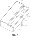
- Fig. 7 is a structural view ( I ) of a first housing cover of the atomizing generator according to Embodiment 1 of the present invention
- Fig. 8 is a structural view ( II ) of the first housing cover of the atomizing generator according to Embodiment 1 of the present invention.
- the housing 41 includes the housing body 411, the first housing cover 412, and the second housing cover 413
- the partition plate 417 is disposed in the housing body 411 to divide the housing body 411 into the atomizing cavity 42 and the mounting cavity 43
- the liquid inlet 4112 and the mist outlet 4113 are arranged on the bottom surface of the housing body 411 at a side corresponding to the atomizing cavity 42
- the air inlet 4111 is disposed at the position of the side surface of the housing body 411 corresponding to the mounting cavity 43
- the fan 48 is disposed in the air inlet 4111
- the partition plate 417 is provided with the notch 4171
- the fan 48 introduces air outside the housing body 411 into the housing body 411, with most of the air reaching the atomizing cavity 42 through the notch 4171.
- the water-permeable hole (not shown) is also provided at the bottom of the housing body 411, and the atomizing element 44 is preferably an ultrasonic atomizing film provided outside the housing body 411 and hermetically connected at the water-permeable hole by the atomizing film holder 416 for atomizing the liquid in the atomizing cavity 42 into a mist.
- the first housing cover 412 is provided with the transverse rib 414 and the vertical rib 415, the transverse rib 414 is fixedly connected to three sequentially adjacent inner side surfaces of the first housing cover 412, and the vertical rib 415 is fixedly connected to the top surface of the first housing cover 412 and two opposite ones of the three sequentially adjacent inner side surfaces, so that the transverse rib 414, the vertical rib 415 and three sequentially adjacent inner side surfaces jointly enclose the communicating cavity, and the second housing cover 413 can cover the communicating cavity.
- the transverse rib 414, the vertical rib 415 and three sequentially adjacent inner side surfaces jointly enclose the communicating cavity
- the second housing cover 413 can cover the communicating cavity.
- the transverse rib 414 is provided with the first communication hole 4141 and the second communication hole 4142 corresponding to the atomizing cavity 42 and the mist outlet 4113, the atomizing cavity 42 is connected to the communicating cavity through the first communication hole 4141, and the mist outlet 4113 is connected to the second communication hole 4142 through the connecting pipe 46.
- the wind shield 4143 extends downwards from the bottom surface of the transverse rib 414 into the atomizing cavity 42 and is arranged corresponding to the notch 4171.
- the valve mechanism 45 includes the drive portion 451 and the sealing block 452, the drive portion 451 is connected to the sealing block 452 and is capable of driving the sealing block 452 to slide reciprocally within the communicating cavity.
- the drive portion 451 has an output shaft fixedly connected to the sealing block 452 to drive the sealing block 452 to slide in the communicating cavity.
- the bottom surface of the sealing block 452 is capable of covering both the first communication hole 4141 and the second communication hole 4142, and the holes may be properly sealed when covered.
- the controller 47 is further provided in the mounting cavity 43 at a position facing the air inlet 4111, the controller 47 is connected to the ultrasonic atomizing film, the drive portion 451 and the fan 48, respectively, for controlling the start/stop of the ultrasonic atomizing film, the drive portion 451 and the fan 48, respectively.
- the above arrangement is advantageous in that the communicating cavity is arranged on the first housing cover while the mist outlet 4113 is arranged on the bottom surface of the housing body 411, and the mist outlet 4113 is connected to the second communication hole 4142 through the communication pipe, hence a complete air flow passage is formed among the atomizing cavity 42, the communicating cavity and the communication pipe, and the mist is naturally and strongly discharged in conjunction with the action of the fan 48.
- the arrangement of the mist outlet 4113 on the bottom surface of the housing 41 facilitates the connection with the mist outlet pipe 7, the mist outlet pipe 7 can be connected to the outer drum 3 without bending, which shortens a stroke of spraying the mist and improves the effect of spraying the mist.
- the sealing block 452 to cover and seal both the first communication hole 4141 and the second communication hole 4142 renders better effects in blocking and sealing the damp-heat air with the valve mechanism 45.
- the air inlet 4111 is arranged corresponding to the mounting cavity 43, the controller 47 is arranged at the position facing the air inlet 4111, so that the fan 48 can be used for dissipating heat from the controller 47 when the atomizing generator 4 works, which improves the service life and the stability of the controller 47.
- the arrangement of the wind shield 4143 extending from the bottom surface of the transverse rib 414 corresponding to the notch 4171 enables the wind blown by the fan 48 to bypass after passing through the notch 4171, so that the mist is better carried by the wind and gets quickly discharged, without remaining in the atomizing cavity 42 while the wind has blown over.
- the atomizing generator 4 utilizes electronic high-frequency oscillation (at a frequency of 1.7 MHz or 2.4 MHz and other frequencies beyond the auditory range, definitely harmless to human bodies and animals), as such, the molecular structure of liquid water is scattered through the high-frequency resonance of the atomizing film to generate naturally a dissipated mist, that is, the water is converted into ultramicro particles sized from 1 to 100 micrometers uniformly without heating or addition of any chemicals. Compared with atomizing by heating, the energy is saved by 90%.
- the arrangement of the valve mechanism 45 is not single and variations on this basis can be obtained by a person skilled in the art as long as the first communication hole 4141 and/or the second communication hole 4142 are sealed thereby.
- an ordinary motor may be selected as the drive portion 451, and a transmission member may be added between the drive portion 451 and the sealing block 452 to enable the reciprocating sliding of the sealing block 452.
- the transmission member may be a ball screw or the like.
- the sealing block 452 may be provided to seal only one of the first communication hole 4141 and the second communication hole 4142, and this would also be enough for the function of preventing the reflux of the damp-heat air.
- a control unit of the drum washing machine may be used to control the start/stop of the drive portion 451, the fan 48 and the ultrasonic atomizing film, without departing from the scope of the present invention as defined by the appended claims.
Landscapes
- Engineering & Computer Science (AREA)
- Textile Engineering (AREA)
- Accessory Of Washing/Drying Machine, Commercial Washing/Drying Machine, Other Washing/Drying Machine (AREA)
- Detail Structures Of Washing Machines And Dryers (AREA)
Claims (8)
- Zerstäubungsgenerator (4), umfassend ein Gehäuse (41), das mit einem Zerstäubungshohlraum (42) darin versehen ist, wobei ein Zerstäubungselement (44), das in der Lage ist, eine Flüssigkeit zu zerstäuben, in dem Zerstäubungshohlraum (42) bereitgestellt ist, ein Lufteinlass (4111), ein Flüssigkeitseinlass (4112) und ein Nebelauslass (4113), die mit dem Zerstäubungshohlraum (42) in Verbindung sind, an dem Gehäuse (41) bereitgestellt sind,wobei in dem Gehäuse (41) ein von dem Zerstäubungshohlraum (42) unabhängiger Verbindungshohlraum gebildet ist, der Zerstäubungshohlraum (42) durch ein erstes Verbindungsloch (4141) mit dem Verbindungshohlraum verbunden ist, der Nebelauslass (4113) durch ein zweites Verbindungsloch (4142) mit dem Verbindungshohlraum verbunden ist, ferner in dem Verbindungshohlraum ein Ventilmechanismus (45) bereitgestellt ist und der Ventilmechanismus (45) konfiguriert ist, um in der Lage zu sein, das erste Verbindungsloch (4141) und/oder das zweite Verbindungsloch (4142) zu verschließen, undwobei das Gehäuse (41) einen Gehäusekörper (411) und einen ersten Gehäusedeckel (412) umfasst, wobei eine Querrippe (414) und eine vertikale Rippe (415) an dem ersten Gehäusedeckel (412) bereitgestellt sind, die Querrippe (414) fest mit drei aufeinanderfolgenden benachbarten inneren Seitenflächen des ersten Gehäusedeckels (412) verbunden ist und die vertikale Rippe (415) fest mit zwei gegenüberliegenden der drei aufeinanderfolgenden benachbarten inneren Seitenflächen verbunden ist, sodass die Querrippe (414), die vertikale Rippe (415) und die drei inneren Seitenflächen gemeinsam den Verbindungshohlraum umschließen, dadurch gekennzeichnet, dass das erste Verbindungsloch (4141) und das zweite Verbindungsloch (4142) an der Querrippe (414) angeordnet sind, der Nebelauslass (4113) an einem Boden des Gehäuses (41) angeordnet ist, der Zerstäubungsgenerator (4) ferner ein Verbindungsrohr (46) umfasst und der Nebelauslass (4113) durch das Verbindungsrohr (46) mit dem zweiten Verbindungsloch (4142) verbunden ist.
- Zerstäubungsgenerator (4) nach Anspruch 1, dadurch gekennzeichnet, dass der Ventilmechanismus (45) einen Antriebsabschnitt (451) und einen Dichtungsblock (452) umfasst, wobei der Antriebsabschnitt (451) in der Lage ist, den Dichtungsblock (452) anzutreiben, um in dem Verbindungshohlraum hin und her zu gleiten.
- Zerstäubungsgenerator (4) nach Anspruch 1, dadurch gekennzeichnet, dass das Gehäuse (41) ferner einen zweiten Gehäusedeckel (413) umfasst, der in der Lage ist, den Verbindungshohlraum abzudecken.
- Zerstäubungsgenerator (4) nach Anspruch 1, dadurch gekennzeichnet, dass eine Teilerplatte (417) in dem Gehäuse (41) bereitgestellt ist und das Gehäuse (41) in einen Montagehohlraum (43) und den Zerstäubungshohlraum (42) unterteilt, eine Steuerung (47) in dem Montagehohlraum (43) bereitgestellt ist und mit dem Zerstäubungselement (44) bzw. dem Ventilmechanismus (45) verbunden ist, um den Start/Stopp des Zerstäubungselements (44) und das Öffnen/Schließen des Ventilmechanismus (45) zu steuern.
- Zerstäubungsgenerator (4) nach Anspruch 4, dadurch gekennzeichnet, dass die Teilerplatte (417) mit einer Kerbe (4171) versehen ist, sich ein Windschutz (4143) von einer Bodenfläche der Querrippe (414) nach unten erstreckt, und sich der Windschutz (4143) in den Zerstäubungshohlraum (42) erstreckt und entsprechend der Kerbe (4171) angeordnet ist.
- Zerstäubungsgenerator (4) nach Anspruch 4, dadurch gekennzeichnet, dass der Lufteinlass (4111) mit einem Lüfter (48) versehen ist und die Steuerung (47) ferner mit dem Lüfter (48) verbunden ist, um den Start/Stopp des Lüfters (8) zu steuern.
- Zerstäubungsgenerator (4) nach Anspruch 1, dadurch gekennzeichnet, dass das Zerstäubungselement (44) ein Ultraschall-Zerstäubungsfilm ist, ein Boden des Gehäuses (41) mit einem wasserdurchlässigen Loch versehen ist und der Ultraschall-Zerstäubungsfilm außerhalb des Gehäuses (41) entsprechend dem wasserdurchlässigen Loch platziert ist.
- Wäschebehandlungsvorrichtung, umfassend einen Tank (1) und eine Wäschetrommel, die in dem Tank (1) bereitgestellt ist, dadurch gekennzeichnet, dass sie ferner ein Trocknungsmodul (5) und den Zerstäubungsgenerator (4) nach einem der Ansprüche 1 bis 7 umfasst, wobei der Flüssigkeitseinlass (4112) des Zerstäubungsgenerators (4) durch ein Flüssigkeitseinlassrohr (6) mit einer Wasserquelle in Verbindung ist und der Nebelauslass (4113) durch ein Nebelauslassrohr (7) mit der Wäschetrommel in Verbindung ist.
Applications Claiming Priority (5)
| Application Number | Priority Date | Filing Date | Title |
|---|---|---|---|
| CN201910060553 | 2019-01-22 | ||
| CN201910165012.2A CN111472140B (zh) | 2019-01-22 | 2019-03-05 | 雾化发生器及包括该雾化发生器的衣物处理设备 |
| CN201910165475.9A CN111472141A (zh) | 2019-01-22 | 2019-03-05 | 雾化发生器及包括该雾化发生器的衣物处理设备 |
| EP20745012.3A EP3916146B1 (de) | 2019-01-22 | 2020-01-06 | Zerstäubungsgenerator und vorrichtung zur behandlung von wäsche mit dem zerstäubungsgenerator |
| PCT/CN2020/070458 WO2020151485A1 (zh) | 2019-01-22 | 2020-01-06 | 雾化发生器及包括该雾化发生器的衣物处理设备 |
Related Parent Applications (2)
| Application Number | Title | Priority Date | Filing Date |
|---|---|---|---|
| EP20745012.3A Division EP3916146B1 (de) | 2019-01-22 | 2020-01-06 | Zerstäubungsgenerator und vorrichtung zur behandlung von wäsche mit dem zerstäubungsgenerator |
| EP20745012.3A Division-Into EP3916146B1 (de) | 2019-01-22 | 2020-01-06 | Zerstäubungsgenerator und vorrichtung zur behandlung von wäsche mit dem zerstäubungsgenerator |
Publications (3)
| Publication Number | Publication Date |
|---|---|
| EP4043103A1 EP4043103A1 (de) | 2022-08-17 |
| EP4043103C0 EP4043103C0 (de) | 2025-04-09 |
| EP4043103B1 true EP4043103B1 (de) | 2025-04-09 |
Family
ID=71736314
Family Applications (1)
| Application Number | Title | Priority Date | Filing Date |
|---|---|---|---|
| EP22164921.3A Active EP4043103B1 (de) | 2019-01-22 | 2020-01-06 | Zerstäubungsgenerator und vorrichtung zur behandlung von wäsche mit dem zerstäubungsgenerator |
Country Status (4)
| Country | Link |
|---|---|
| US (2) | US11807976B2 (de) |
| EP (1) | EP4043103B1 (de) |
| JP (1) | JP7161061B2 (de) |
| WO (1) | WO2020151485A1 (de) |
Families Citing this family (4)
| Publication number | Priority date | Publication date | Assignee | Title |
|---|---|---|---|---|
| CN113863000A (zh) * | 2021-11-01 | 2021-12-31 | 浙江莹隆纤维科技有限公司 | 一种三维荧光石墨烯纤维的制备方法 |
| US11585030B1 (en) * | 2021-12-11 | 2023-02-21 | Eve Street Designs Pty Ltd. | Portable plunger-wash bag apparatus and method of use to clean laundry |
| CN117144640A (zh) * | 2022-05-23 | 2023-12-01 | 无锡小天鹅电器有限公司 | 一种衣物处理设备 |
| CN115321616B (zh) * | 2022-09-23 | 2024-03-29 | 西安稀有金属材料研究院有限公司 | 一种低成本、粒度可控的高比表面积纳米氧化钌制备方法 |
Family Cites Families (15)
| Publication number | Priority date | Publication date | Assignee | Title |
|---|---|---|---|---|
| FR2746656B1 (fr) * | 1996-03-26 | 1999-05-28 | System Assistance Medical | Nebuliseur a capteur de pression |
| DE20211577U1 (de) * | 2002-07-15 | 2003-11-27 | Bolte, Georg, Dr. | Vorrichtung zur kontrollierten Erzeugung von Aerosolen |
| JP2008539890A (ja) * | 2005-05-05 | 2008-11-20 | プルマトリックス インコーポレイテッド | 超音波式エアロゾルゼネレーター |
| JP4384192B2 (ja) * | 2007-02-14 | 2009-12-16 | パナソニック株式会社 | ドラム式洗濯乾燥機 |
| CN201033315Y (zh) * | 2007-04-02 | 2008-03-12 | 佛山市顺德区雅洛特电器有限公司 | 超声波雾化发生器 |
| JP4935744B2 (ja) * | 2008-04-10 | 2012-05-23 | パナソニック株式会社 | 洗濯機 |
| FR2972444B1 (fr) * | 2011-03-07 | 2013-10-18 | Peugeot Citroen Automobiles Sa | Dispositif de decontamination d'un liquide, systeme de rafraichissement d'air par nebulisation muni d'un tel dispositif, procede de rafraichissement, et vehicule automobile associe |
| DE102012213934A1 (de) * | 2012-08-07 | 2014-02-13 | BSH Bosch und Siemens Hausgeräte GmbH | Waschmaschine mit Vorrichtung zur Erzeugung von Wassertropfen sowie Verfahren zu ihrem Betrieb |
| JP6333036B2 (ja) | 2014-04-15 | 2018-05-30 | アクア株式会社 | オゾン処理装置 |
| KR102227372B1 (ko) * | 2014-04-21 | 2021-03-11 | 엘지전자 주식회사 | 세탁방법 |
| US9480767B1 (en) | 2015-10-20 | 2016-11-01 | Prolitec Inc. | Removable cartridge and cap assembly for an air treatment appliance |
| FR3050146B1 (fr) * | 2016-04-18 | 2019-04-19 | Valeo Systemes Thermiques | Dispositif de rafraichissement d'air pour vehicule et installation de chauffage, de ventilation et/ou de climatisation associee |
| CN107780134B (zh) * | 2016-08-30 | 2020-05-05 | 青岛海尔滚筒洗衣机有限公司 | 一种具有蒸汽洗涤护理功能的洗衣机 |
| CN208032903U (zh) * | 2018-02-11 | 2018-11-02 | 泓道(上海)科技有限公司 | 雾化器 |
| CN111472140B (zh) * | 2019-01-22 | 2022-05-27 | 青岛海尔洗衣机有限公司 | 雾化发生器及包括该雾化发生器的衣物处理设备 |
-
2020
- 2020-01-06 WO PCT/CN2020/070458 patent/WO2020151485A1/zh not_active Ceased
- 2020-01-06 US US17/423,994 patent/US11807976B2/en active Active
- 2020-01-06 EP EP22164921.3A patent/EP4043103B1/de active Active
- 2020-01-06 JP JP2021542333A patent/JP7161061B2/ja active Active
-
2022
- 2022-03-23 US US17/701,924 patent/US11807977B2/en active Active
Also Published As
| Publication number | Publication date |
|---|---|
| EP4043103A1 (de) | 2022-08-17 |
| JP7161061B2 (ja) | 2022-10-25 |
| JP2022518755A (ja) | 2022-03-16 |
| EP4043103C0 (de) | 2025-04-09 |
| US11807977B2 (en) | 2023-11-07 |
| WO2020151485A1 (zh) | 2020-07-30 |
| US11807976B2 (en) | 2023-11-07 |
| US20220213634A1 (en) | 2022-07-07 |
| US20220081821A1 (en) | 2022-03-17 |
Similar Documents
| Publication | Publication Date | Title |
|---|---|---|
| EP3916146B1 (de) | Zerstäubungsgenerator und vorrichtung zur behandlung von wäsche mit dem zerstäubungsgenerator | |
| US11807977B2 (en) | Atomizing generator and clothes treatment apparatus comprising the atomizing generator | |
| US6954995B2 (en) | Drying/washing machine | |
| JP6362830B2 (ja) | 家電機器 | |
| EP2319979B1 (de) | Waschmaschine/trockner | |
| TWI422722B (zh) | Laundry dryer | |
| CN210117537U (zh) | 雾化发生器、衣物处理设备 | |
| CN111663281B (zh) | 雾化发生器、衣物处理设备及其控制方法 | |
| TWI475140B (zh) | Washing machine (1) | |
| CN111663302A (zh) | 用于衣物处理设备的雾化装置、衣物处理设备及控制方法 | |
| US12043946B2 (en) | Atomising generator, clothing treatment device, and control method therefor | |
| CN110076141A (zh) | 一种等离子清洗装置 | |
| CN210117540U (zh) | 波轮洗衣机 | |
| JP5306148B2 (ja) | 洗濯乾燥機 | |
| CN115874430B (zh) | 一种挂烫机及其主机 | |
| CN111663288A (zh) | 波轮洗衣机 | |
| CN212481536U (zh) | 一种基于高频电离原理的空气消毒机 | |
| CN111058214A (zh) | 波轮洗衣机 | |
| CN223867001U (zh) | 一种衣物处理设备 | |
| KR200360038Y1 (ko) | 가습기의 가열장치 | |
| TW201725052A (zh) | 消毒機之加濕結構 | |
| CN121363101A (zh) | 衣物处理设备 | |
| KR19990017494A (ko) | 전자렌지 | |
| KR19990017495A (ko) | 전자렌지 | |
| KR19990017492A (ko) | 전자렌지 |
Legal Events
| Date | Code | Title | Description |
|---|---|---|---|
| PUAI | Public reference made under article 153(3) epc to a published international application that has entered the european phase |
Free format text: ORIGINAL CODE: 0009012 |
|
| STAA | Information on the status of an ep patent application or granted ep patent |
Free format text: STATUS: THE APPLICATION HAS BEEN PUBLISHED |
|
| AC | Divisional application: reference to earlier application |
Ref document number: 3916146 Country of ref document: EP Kind code of ref document: P |
|
| AK | Designated contracting states |
Kind code of ref document: A1 Designated state(s): AL AT BE BG CH CY CZ DE DK EE ES FI FR GB GR HR HU IE IS IT LI LT LU LV MC MK MT NL NO PL PT RO RS SE SI SK SM TR |
|
| STAA | Information on the status of an ep patent application or granted ep patent |
Free format text: STATUS: REQUEST FOR EXAMINATION WAS MADE |
|
| 17P | Request for examination filed |
Effective date: 20230216 |
|
| RBV | Designated contracting states (corrected) |
Designated state(s): AL AT BE BG CH CY CZ DE DK EE ES FI FR GB GR HR HU IE IS IT LI LT LU LV MC MK MT NL NO PL PT RO RS SE SI SK SM TR |
|
| GRAP | Despatch of communication of intention to grant a patent |
Free format text: ORIGINAL CODE: EPIDOSNIGR1 |
|
| STAA | Information on the status of an ep patent application or granted ep patent |
Free format text: STATUS: GRANT OF PATENT IS INTENDED |
|
| INTG | Intention to grant announced |
Effective date: 20250110 |
|
| GRAS | Grant fee paid |
Free format text: ORIGINAL CODE: EPIDOSNIGR3 |
|
| GRAA | (expected) grant |
Free format text: ORIGINAL CODE: 0009210 |
|
| STAA | Information on the status of an ep patent application or granted ep patent |
Free format text: STATUS: THE PATENT HAS BEEN GRANTED |
|
| AC | Divisional application: reference to earlier application |
Ref document number: 3916146 Country of ref document: EP Kind code of ref document: P |
|
| AK | Designated contracting states |
Kind code of ref document: B1 Designated state(s): AL AT BE BG CH CY CZ DE DK EE ES FI FR GB GR HR HU IE IS IT LI LT LU LV MC MK MT NL NO PL PT RO RS SE SI SK SM TR |
|
| REG | Reference to a national code |
Ref country code: GB Ref legal event code: FG4D |
|
| RIN1 | Information on inventor provided before grant (corrected) |
Inventor name: SUN, GUANGBIN Inventor name: ZHUANG, ZHONGKAI Inventor name: WANG, DEJUN Inventor name: ZHAO, ZHIQIANG Inventor name: XU, SHENG |
|
| REG | Reference to a national code |
Ref country code: CH Ref legal event code: EP |
|
| REG | Reference to a national code |
Ref country code: DE Ref legal event code: R096 Ref document number: 602020049381 Country of ref document: DE |
|
| REG | Reference to a national code |
Ref country code: IE Ref legal event code: FG4D |
|
| U01 | Request for unitary effect filed |
Effective date: 20250425 |
|
| U07 | Unitary effect registered |
Designated state(s): AT BE BG DE DK EE FI FR IT LT LU LV MT NL PT RO SE SI Effective date: 20250502 |
|
| PG25 | Lapsed in a contracting state [announced via postgrant information from national office to epo] |
Ref country code: ES Free format text: LAPSE BECAUSE OF FAILURE TO SUBMIT A TRANSLATION OF THE DESCRIPTION OR TO PAY THE FEE WITHIN THE PRESCRIBED TIME-LIMIT Effective date: 20250409 |
|
| PG25 | Lapsed in a contracting state [announced via postgrant information from national office to epo] |
Ref country code: GR Free format text: LAPSE BECAUSE OF FAILURE TO SUBMIT A TRANSLATION OF THE DESCRIPTION OR TO PAY THE FEE WITHIN THE PRESCRIBED TIME-LIMIT Effective date: 20250710 Ref country code: NO Free format text: LAPSE BECAUSE OF FAILURE TO SUBMIT A TRANSLATION OF THE DESCRIPTION OR TO PAY THE FEE WITHIN THE PRESCRIBED TIME-LIMIT Effective date: 20250709 |
|
| PG25 | Lapsed in a contracting state [announced via postgrant information from national office to epo] |
Ref country code: PL Free format text: LAPSE BECAUSE OF FAILURE TO SUBMIT A TRANSLATION OF THE DESCRIPTION OR TO PAY THE FEE WITHIN THE PRESCRIBED TIME-LIMIT Effective date: 20250409 |
|
| PG25 | Lapsed in a contracting state [announced via postgrant information from national office to epo] |
Ref country code: HR Free format text: LAPSE BECAUSE OF FAILURE TO SUBMIT A TRANSLATION OF THE DESCRIPTION OR TO PAY THE FEE WITHIN THE PRESCRIBED TIME-LIMIT Effective date: 20250409 |
|
| PG25 | Lapsed in a contracting state [announced via postgrant information from national office to epo] |
Ref country code: RS Free format text: LAPSE BECAUSE OF FAILURE TO SUBMIT A TRANSLATION OF THE DESCRIPTION OR TO PAY THE FEE WITHIN THE PRESCRIBED TIME-LIMIT Effective date: 20250709 |
|
| PG25 | Lapsed in a contracting state [announced via postgrant information from national office to epo] |
Ref country code: IS Free format text: LAPSE BECAUSE OF FAILURE TO SUBMIT A TRANSLATION OF THE DESCRIPTION OR TO PAY THE FEE WITHIN THE PRESCRIBED TIME-LIMIT Effective date: 20250809 |
|
| PG25 | Lapsed in a contracting state [announced via postgrant information from national office to epo] |
Ref country code: SM Free format text: LAPSE BECAUSE OF FAILURE TO SUBMIT A TRANSLATION OF THE DESCRIPTION OR TO PAY THE FEE WITHIN THE PRESCRIBED TIME-LIMIT Effective date: 20250409 |
|
| PG25 | Lapsed in a contracting state [announced via postgrant information from national office to epo] |
Ref country code: CZ Free format text: LAPSE BECAUSE OF FAILURE TO SUBMIT A TRANSLATION OF THE DESCRIPTION OR TO PAY THE FEE WITHIN THE PRESCRIBED TIME-LIMIT Effective date: 20250409 |
|
| PG25 | Lapsed in a contracting state [announced via postgrant information from national office to epo] |
Ref country code: SK Free format text: LAPSE BECAUSE OF FAILURE TO SUBMIT A TRANSLATION OF THE DESCRIPTION OR TO PAY THE FEE WITHIN THE PRESCRIBED TIME-LIMIT Effective date: 20250409 |
|
| PLBE | No opposition filed within time limit |
Free format text: ORIGINAL CODE: 0009261 |
|
| STAA | Information on the status of an ep patent application or granted ep patent |
Free format text: STATUS: NO OPPOSITION FILED WITHIN TIME LIMIT |
|
| REG | Reference to a national code |
Ref country code: CH Ref legal event code: L10 Free format text: ST27 STATUS EVENT CODE: U-0-0-L10-L00 (AS PROVIDED BY THE NATIONAL OFFICE) Effective date: 20260218 |
|
| U20 | Renewal fee for the european patent with unitary effect paid |
Year of fee payment: 7 Effective date: 20260129 |
|
| 26N | No opposition filed |
Effective date: 20260112 |