EP4043177A1 - Vis de moulage, machine de moulage par injection pour procédé de mélange libre et procédé de fabrication de corps moulé en résine dans un procédé de mélange libre - Google Patents
Vis de moulage, machine de moulage par injection pour procédé de mélange libre et procédé de fabrication de corps moulé en résine dans un procédé de mélange libre Download PDFInfo
- Publication number
- EP4043177A1 EP4043177A1 EP20874247.8A EP20874247A EP4043177A1 EP 4043177 A1 EP4043177 A1 EP 4043177A1 EP 20874247 A EP20874247 A EP 20874247A EP 4043177 A1 EP4043177 A1 EP 4043177A1
- Authority
- EP
- European Patent Office
- Prior art keywords
- molding
- screw
- flights
- blending
- sub
- Prior art date
- Legal status (The legal status is an assumption and is not a legal conclusion. Google has not performed a legal analysis and makes no representation as to the accuracy of the status listed.)
- Granted
Links
Images






Classifications
-
- B—PERFORMING OPERATIONS; TRANSPORTING
- B29—WORKING OF PLASTICS; WORKING OF SUBSTANCES IN A PLASTIC STATE IN GENERAL
- B29C—SHAPING OR JOINING OF PLASTICS; SHAPING OF MATERIAL IN A PLASTIC STATE, NOT OTHERWISE PROVIDED FOR; AFTER-TREATMENT OF THE SHAPED PRODUCTS, e.g. REPAIRING
- B29C45/00—Injection moulding, i.e. forcing the required volume of moulding material through a nozzle into a closed mould; Apparatus therefor
- B29C45/17—Component parts, details or accessories; Auxiliary operations
- B29C45/46—Means for plasticising or homogenising the moulding material or forcing it into the mould
- B29C45/47—Means for plasticising or homogenising the moulding material or forcing it into the mould using screws
- B29C45/50—Axially movable screw
-
- B—PERFORMING OPERATIONS; TRANSPORTING
- B29—WORKING OF PLASTICS; WORKING OF SUBSTANCES IN A PLASTIC STATE IN GENERAL
- B29B—PREPARATION OR PRETREATMENT OF THE MATERIAL TO BE SHAPED; MAKING GRANULES OR PREFORMS; RECOVERY OF PLASTICS OR OTHER CONSTITUENTS OF WASTE MATERIAL CONTAINING PLASTICS
- B29B7/00—Mixing; Kneading
- B29B7/30—Mixing; Kneading continuous, with mechanical mixing or kneading devices
- B29B7/34—Mixing; Kneading continuous, with mechanical mixing or kneading devices with movable mixing or kneading devices
- B29B7/38—Mixing; Kneading continuous, with mechanical mixing or kneading devices with movable mixing or kneading devices rotary
- B29B7/40—Mixing; Kneading continuous, with mechanical mixing or kneading devices with movable mixing or kneading devices rotary with single shaft
- B29B7/42—Mixing; Kneading continuous, with mechanical mixing or kneading devices with movable mixing or kneading devices rotary with single shaft with screw or helix
- B29B7/428—Parts or accessories, e.g. casings, feeding or discharging means
- B29B7/429—Screws
-
- B—PERFORMING OPERATIONS; TRANSPORTING
- B29—WORKING OF PLASTICS; WORKING OF SUBSTANCES IN A PLASTIC STATE IN GENERAL
- B29B—PREPARATION OR PRETREATMENT OF THE MATERIAL TO BE SHAPED; MAKING GRANULES OR PREFORMS; RECOVERY OF PLASTICS OR OTHER CONSTITUENTS OF WASTE MATERIAL CONTAINING PLASTICS
- B29B7/00—Mixing; Kneading
- B29B7/80—Component parts, details or accessories; Auxiliary operations
- B29B7/88—Adding charges, i.e. additives
-
- B—PERFORMING OPERATIONS; TRANSPORTING
- B29—WORKING OF PLASTICS; WORKING OF SUBSTANCES IN A PLASTIC STATE IN GENERAL
- B29C—SHAPING OR JOINING OF PLASTICS; SHAPING OF MATERIAL IN A PLASTIC STATE, NOT OTHERWISE PROVIDED FOR; AFTER-TREATMENT OF THE SHAPED PRODUCTS, e.g. REPAIRING
- B29C45/00—Injection moulding, i.e. forcing the required volume of moulding material through a nozzle into a closed mould; Apparatus therefor
- B29C45/03—Injection moulding apparatus
-
- B—PERFORMING OPERATIONS; TRANSPORTING
- B29—WORKING OF PLASTICS; WORKING OF SUBSTANCES IN A PLASTIC STATE IN GENERAL
- B29C—SHAPING OR JOINING OF PLASTICS; SHAPING OF MATERIAL IN A PLASTIC STATE, NOT OTHERWISE PROVIDED FOR; AFTER-TREATMENT OF THE SHAPED PRODUCTS, e.g. REPAIRING
- B29C45/00—Injection moulding, i.e. forcing the required volume of moulding material through a nozzle into a closed mould; Apparatus therefor
- B29C45/17—Component parts, details or accessories; Auxiliary operations
- B29C45/46—Means for plasticising or homogenising the moulding material or forcing it into the mould
- B29C45/47—Means for plasticising or homogenising the moulding material or forcing it into the mould using screws
- B29C45/50—Axially movable screw
- B29C45/5008—Drive means therefor
-
- B—PERFORMING OPERATIONS; TRANSPORTING
- B29—WORKING OF PLASTICS; WORKING OF SUBSTANCES IN A PLASTIC STATE IN GENERAL
- B29C—SHAPING OR JOINING OF PLASTICS; SHAPING OF MATERIAL IN A PLASTIC STATE, NOT OTHERWISE PROVIDED FOR; AFTER-TREATMENT OF THE SHAPED PRODUCTS, e.g. REPAIRING
- B29C45/00—Injection moulding, i.e. forcing the required volume of moulding material through a nozzle into a closed mould; Apparatus therefor
- B29C45/17—Component parts, details or accessories; Auxiliary operations
- B29C45/46—Means for plasticising or homogenising the moulding material or forcing it into the mould
- B29C45/58—Details
- B29C45/60—Screws
Definitions
- the present disclosure relates to an injection molding machine used in free blend injection in which a powder made of various materials including metal and wood pieces and a resin powder are directly mixed and molded, as well as a molding screw used in the injection molding machine, and a free blend-type resin molded body manufacturing method.
- One method of manufacturing a desired product using resin is injection molding, in which the resin is melted and molded using a mold.
- injection molding pellets formed into a certain shape in advance are introduced from a hopper into a cylinder and are melted and kneaded with a molding screw while being moved toward the outlet side, and the melted resin is poured into a mold to mold a resin product.
- resin materials that have various functions and characteristics by pre-processing such resin materials into pellets that have a certain shape in advance, it is possible to manufacture various resin molded bodies using the same resin molding machine.
- Resin molded articles are generally often mass-produced. Accordingly, it is important in manufacturing to reduce variation in the quality of manufactured resin molded articles. To achieve this, an injection molding machine is required to have a device structure that is capable of sufficiently melting and kneading a resin material. Efforts are underway to develop a screw that is the key to achieving this.
- This screw includes a mixing portion at the leading end of the metering zone (mold-side portion) and in the region corresponding to the outer peripheral surface of a plunger arranged at a distance (clearance) from the cylinder.
- the mixing portion includes dead-end grooves that are closed at one end, and the grooves are alternatingly arranged in opposite directions so as not to be in communication with each other.
- This mixing portion has a structure in which a main flight having a small clearance with the cylinder and sub flights having a slightly larger clearance than the main flight are arranged alternatingly, and the sub flights are arranged discontinuously to form protrusions and recessions.
- Amolding screw developed for the purpose of improving kneading action and making the resin temperature uniform has also been disclosed.
- screw groove bottom surfaces extend between screw flights from an intermediate point in the compressing portion to an intermediate point in the metering portion, such screw groove bottom surfaces are alternatingly shifted in the radial direction along the screw flights, and the screw groove bottom surfaces on the shifted side form protrusions and recessions (e.g., see Patent Document 2).
- An injection molding machine and a screw capable of uniformly dispersing reinforcing fibers in melted resin when the reinforcing fibers are mixed with the melted resin and injection molded have also been disclosed.
- the screw provided in this injection molding machine is provided with a kneading portion on the downstream side of the compressing portion.
- Three spiral-shaped groove portions are formed extending in the direction opposite to the orientation of the flights in the kneading portion. These groove portions prevent the reinforcing fibers from being broken, and can maintain the fiber length.
- a device for performing injection molding directly from a raw material resin without pelletizing the resin, and a screw used for the same, have also been disclosed.
- This device has good melting, kneading, and dispersion capabilities for the raw material resin, and can obtain a resin molded article that has excellent mechanical strength as a molded article.
- the screw used in this device includes a double wave structure constituted by first wave grooves and second wave grooves that spiral in the axial direction between screw flights. Regarding the elliptical shape of the cross section of the first wave grooves and the second wave grooves in this screw structure, their major axes have a constant angle ⁇ of 30 to 150° and a deviation angle ⁇ of 90° (e.g., see Patent Document 4).
- Patent Document 1 aims to improve resin kneading capability and dispersion, but there is no disclosure or suggestion regarding the use of materials other than resins.
- Patent Document 2 aims to make the resin temperature uniform by improving the kneading action.
- resins such as polypropylene (PP) and polyethylene (PE), but there is no disclosure or suggestion of using materials other than resins.
- An object of the invention described in Patent Document 3 is to produce a composite resin molded body that includes a thermoplastic resin and reinforcing fibers by using an injection molding method.
- thermoplastic resin pellets provided with reinforcing fibers in advance are used, and there is no disclosure or suggestion of using reinforcing fibers not provided in pellets.
- Patent Document 4 The invention described in Patent Document 4 is directed to performing injection molding directly using a raw material resin without pelletizing it.
- a raw material resin without pelletizing it.
- only the characteristics of a molded article molded using recycled PET or a modifier and cap waste recycled polyolefin as the raw material resin are shown.
- PET, polyolefins such as polyethylene and polypropylene, and the like can be used the raw material resin, but that the resin is not particularly limited to such examples. From this disclosure content, it can be determined that there is no disclosure or suggestion regarding the manufacture of a molded body containing a material other than resin.
- Resins are used in various fields due to having excellent processability, being inexpensive, and having high durability.
- waste processing has become a major issue.
- resin waste discarded from homes and factories is separated out and partially reused.
- the majority of resin waste is buried or incinerated. Burial causes environmental destruction, and incineration is not desirable from the viewpoint of protecting the global environment. Therefore, the reuse of resin molded articles after use is desired.
- metal products, wood products, ceramic products, and organic substances such as coffee slag that have not been able be used in manufacturing or after being used in products. If such materials can be mixed with resin to produce products with new added value, not only will resources be used effectively, but this is also environmentally friendly.
- pellets are prepared in advance, and the pellets are mixed and kneaded for molding.
- a resin molded body is manufactured using a conventional resin molding machine with the use of a mixture of various materials instead of using pellets, there is a problem that the quality of the product varies a large amount.
- An object of the present invention is to obtain a molded article that has little manufacturing variation and quality variation even when manufacturing a resin molded article with use of a mixture material such as a metal material, wood, ceramic, stone, resin, or an organic material such as squeezed coffee residue, along with a resin powder and a suitable additive.
- a mixture material such as a metal material, wood, ceramic, stone, resin, or an organic material such as squeezed coffee residue
- a molding screw is for use in a free blend injection molding machine (hereinafter called an "FBI molding machine"), and includes: a feeding portion configured to feed a molding material that includes a mixture material, a resin powder, and an additive; and a compressing portion and a metering portion that extend continuously from the feeding portion, and a spiral flight is formed in each of the feeding portion and the compressing portion.
- the flight of the compressing portion includes a plurality of sub flights that extend in a spiral manner in a screw axis direction.
- the sub flights each have a polygonal shape with rounded corner portions, and the sub flights are arranged such that the corner portions are shifted by a set angle with respect to a screw axis.
- the sub flights are formed such that gaps between a cylinder inner surface and the corner portions are smallest and gaps between the cylinder inner surface and central portions between the corner portions are largest.
- the metering portion is provided with a plurality of blending/aligning portions each having gear-like protrusions and recessions in a circumferential direction about the screw axis.
- the molding screw has a plurality of configurations that are different with respect to at least one among the number of flights of the compressing portion, the number or polygonal shape of the sub flights, the number of blending/aligning portions in the metering portion, the shape or number of gear-like protrusions and recessions of the blending/aligning portions, and the length of the blending/aligning portions in the screw axis direction.
- a configuration is possible in which four of the sub flights are provided, and the sub flights are each shaped as an equilateral triangle, have curved surfaces that recede toward the screw axis between the corner portions, and are arranged such that the corner portions are shifted by an angle of 30° each in a view along the screw axis direction.
- a configuration is possible in which four of the sub flights are provided, and the sub flights are each shaped as a square, and are arranged such that the corner portions are shifted by an angle of 22.5° each in a view along the screw axis direction.
- a configuration is possible in which three of the sub flights are provided, and the sub flights are each shaped as an equilateral triangle, have curved surfaces that recede toward the screw axis between the corner portions, and are arranged such that the corner portions are shifted by an angle of 45° each in a view along the screw axis direction.
- a configuration is possible in which the blending/aligning portions of the metering portion have an identical shape and are arranged such that positions of the protrusions and recessions match each other.
- a configuration is possible in which the blending/aligning portions of the metering portion have different lengths in the screw axis direction, are arranged such that the length is different between adjacent blending/aligning portions, and are arranged such that positions of the protrusions and recessions match each other. Furthermore, a configuration is possible in which the blending/aligning portions of the metering portion have different numbers of gear-like protrusions and recessions and are arranged such that the number of gear-like protrusions and recessions is different between adjacent blending/aligning portions.
- the blending/aligning portions of the metering portion have different shapes of gear-like protrusions and recessions and are arranged such that the shape of the gear-like protrusions and recessions is different between adjacent blending/aligning portions.
- the molding screw of the present disclosure includes the compressing portion, in which a plurality of sub flights that have rounded corner portions but are polygonal overall are arranged shifted at a certain angle, and the aligning portion that includes the blending/aligning portions that have gear-like protrusions and recessions.
- the molding material In the regions where the distance between the inner surface of the cylinder and the sub flights is small (the gaps between the cylinder inner surface and the corner portions of the sub flights), the molding material is subjected to stronger compressive force and moves more quickly. On the other hand, in the regions where the distance is large (the gaps between the cylinder inner surface and the central portions between the corner portions), the molding material is subjected to less compressive force and moves more slowly. Uniform kneading is achieved by repeating this fast movement and slow movement. As a result, it is possible to obtain resin molded bodies that have high quality and little manufacturing variation, which are feature of the free blend method.
- the metering portion has a structure in which a plurality of blending/aligning portions provided with gear-like protrusions and recessions are arranged side by side.
- the recession portions the molding material moves more easily, and even a fiber-like mixture material is not likely to be cut, and thus it is possible to increase the proportion of fibers whose length remains the same as at the time of introduction. As a result, a high-strength molded body can be realized.
- the molding screw may have a plurality of configurations that are different with respect to at least one among the number of flights of the compressing portion, the number or polygonal shape of the sub flights, the number of blending/aligning portions in the metering portion, the shape or number of gear-like protrusions and recessions of the blending/aligning portions, and the length of the blending/aligning portions in the screw axis direction.
- This therefore makes it possible to select a molding screw having an optimum configuration in accordance with the molding material. Even in the case where the type of mixture material and resin are appropriately selected in order to realize the function and characteristics of the desired molded body, a molded body having little variation can be obtained by using a molding screw that is in accordance with the selected materials.
- the molding material includes a mixture material, a resin powder, and an additive.
- the mixture material is a material that realizes a function that cannot be obtained with the resin powder alone, and is a concept including recycled materials or remnant materials of resin molded articles, metal materials, ceramic materials, or stone or wood materials, as well as fiber materials such as carbon fiber, glass fiber, or nano cellulose, and organic materials such as coffee slag, paper or materials having or not having a scent component.
- metal materials include not only materials containing a single metal such as iron, copper, aluminum, tungsten, or zirconium, but also an alloy material such as stainless steel or brass.
- the resin molded article referred to here is a product obtained by pulverizing and reusing a molded product, and is a concept including both a thermosetting resin molded article and a thermoplastic resin molded article.
- the resin powder examples include polypropylene (PP) and polyethylene (PE), which are olefin resins, polystyrene (PS), which is a styrene resin, polyphenylene terephthalate (PPS), polybutylene terephthalate (PBT), and polyamide (PA), and any resin material usually used when manufacturing a resin molded body by injection molding can be used without any particular problem.
- PP polypropylene
- PE polyethylene
- PS polystyrene
- PS polyphenylene terephthalate
- PBT polybutylene terephthalate
- PA polyamide
- the free blend method in the present disclosure refers to a method in which a powder or fiber material is introduced into a molding machine and molded without being pelletized in advance.
- a free blend injection molding machine includes: a cylinder provided with a heater configured to heat an interior of the cylinder; a molding screw rotatably provided in the cylinder; a molding machine hopper configured to introduce, into the cylinder, a molding material that includes a mixture material, a resin powder, and an additive; a driving portion configured to drive the molding screw to rotate; and a mold including a back pressure applying portion configured to apply back pressure for pushing the molding screw toward the mold, and a cavity into which the molding material having an increased liquidity is injected, the cavity being provided at a leading end portion side of the molding screw, wherein the molding screw is the molding screw having the above configuration.
- the free blend injection molding machine further includes: a kneading portion that includes a metering hopper configured to meter the mixture material, the resin powder, and the additive, and a mixing drum configured to mix and knead the mixture material, the resin powder, and the additive.
- a configuration is possible in which the molding screw has a plurality of configurations that are different with respect to at least one among the number of flights of the compressing portion, the number or polygonal shape of the sub flights, the number of blending/aligning portions in the metering portion, the shape or number of gear-like protrusions and recessions of the blending/aligning portions, and the length of the blending/aligning portions in the screw axis direction, and one of the configurations of the molding screw is selected for use in accordance with the molding material.
- a free blend-type resin molded body manufacturing method includes the steps of: introducing a molding material that includes a mixture material, a resin powder, and an additive into a molding machine hopper; feeding the introduced molding material from a feeding portion of a molding screw configured to rotate in a cylinder toward an outlet, kneading the molding material with a compressing portion of the screw to perform blending homogenization and alignment, and further kneading and aligning the molding material with a metering portion of the screw while maintaining a blended state; injecting the molding material, which is in a melted state and accumulated at an outlet side of the cylinder, into a mold while applying pre-set back pressure to the screw; and retrieving a resin molded article from the mold after cooling of the molding material that was injected into the mold.
- the molding screw includes the feeding portion configured to feed the molding material, and the compressing portion and the metering portion that extend continuously from the feeding portion, a spiral flight being formed in each of the feeding portion and the compressing portion.
- the flight of the compressing portion includes a plurality of sub flights that extend in a spiral manner in a screw axis direction.
- the sub flights each have a polygonal shape with rounded corner portions, and the sub flights are arranged such that the corner portions are shifted by a set angle with respect to a screw axis.
- the sub flights are formed such that distances between a cylinder inner surface and the corner portions are smallest and distances between the cylinder inner surface and central portions between the corner portions are largest.
- the metering portion is provided with a plurality of blending/aligning portions each having gear-like protrusions and recessions in a circumferential direction about the screw axis. A molding screw having this configuration is used.
- the method further includes the steps of: metering the mixture material, the resin powder, and the additive that constitute the molding material; and kneading the mixture material, the resin powder, and the additive with a mixing drum, wherein the metering step and the kneading step are performed before the molding material is introduced into the molding machine hopper. If the molding material is sufficiently kneaded before being introduced into the molding machine hopper, it is possible to further improve compression, alignment, and kneading performed by the molding screw.
- a configuration is possible in which the molding screw has a plurality of configurations that are different with respect to at least one among the number of flights of the compressing portion, the number or polygonal shape of the sub flights, the number of blending/aligning portions in the metering portion, the shape or number of gear-like protrusions and recessions of the blending/aligning portions, and the length of the blending/aligning portions in the screw axis direction, and one of the configurations of the molding screw is selected for use in accordance with the molding material.
- a configuration may be used in which the molding screw has four sub flights, each sub flight has a triangular shape, curved surfaces that recede toward the screw axis are provided between the corner portions, the corner portions are shifted by an angle of 30° each in a view along the screw axis direction, and the metering portion includes a plurality of blending/aligning portions that have the same shape and are arranged such that the protrusions and recessions match each other.
- a configuration may be used in which the molding screw has four sub flights, each sub flight has a square shape, the corner portions are shifted by an angle of 22.5° each in a view along the screw axis direction, and the metering portion includes a plurality of blending/aligning portions that have different lengths in the screw axis direction and are arranged such that the length is different between adjacent blending/aligning portions, and such that the protrusions and recessions match each other.
- solid powders made of iron, ceramic, or the like and resin powders have very different specific densities, even materials having very different specific densities can be uniformly mixed and kneaded if manufacturing is performed using a molding screw having such a configuration.
- the quality and manufacturing variation can be reduced for the resin molded body, the quality is stable even if the inclusion ratio of solid powder such as iron powder is increased, and it is possible to obtain a surface condition and weight feeling that are closer to those of metal products and ceramic products than in the case of conventional products.
- a molding screw having the following configuration may be used. Specifically, the molding screw has four sub flights, each sub flight has a square shape, the corner portions are shifted by an angle of 22.5° each in a view along the screw axis direction, and the metering portion includes a plurality of blending/aligning portions that have the same shape and are arranged such that the protrusions and recessions match each other.
- mixing uniformity, alignment, and kneading properties can be improved even when a molding material that contains any of various mixture materials is directly introduced into a molding machine. It is possible to provide a molded body that has little product variation, and has high quality and high mechanical strength.
- various materials such as waste plastic, metal waste, fiber material, and natural materials such as wood can be utilized as the mixture material, thus making it possible to provide an environment-friendly molded body.
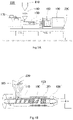
- FIG. 1A is a schematic side view of a free blend injection molding machine 230 according to the present embodiment.
- FIG. 1B is a schematic cross-sectional view of a cylinder portion 150.
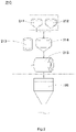
- FIG. 2 is a diagram showing the configuration of a kneading portion 210 used in the present embodiment.
- the kneading portion 210 is constituted by a resin hopper 211 into which a resin powder is introduced, a mixture material hopper 212 into which a mixture material is introduced, a metering hopper 214 that meters the resin powder and the mixture material, an additive hopper 213 into which an additive is introduced, and a mixing drum 215.
- the resin powder and the mixture material are introduced into the resin hopper 211 and the mixture material hopper 212 respectively, and are metered in the metering hopper 214.
- the materials are then introduced into the mixing drum 215. At this time, a required amount of additive is also added from the additive hopper 213.
- the molding screw can have multiple screw configurations that each have at least one difference in terms of the number of flights of the compressing portion N, number or polygonal shape of sub flights, number of blending/aligning portions in the metering portion S, shape and number of gear-like protrusions of the blending/aligning portions, and length of the blending/aligning portions in the screw axis direction, and the optimum screw shape may be selected and used in accordance with the molding material.
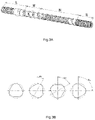
- FIG. 3A is an overall schematic perspective view of the molding screw.
- FIGS. 3B to 3D are diagrams illustrating various shapes and numbers of sub flights of the compressing portion N.
- FIG. 3B is a diagram showing a first example, and shows a configuration in which four triangular sub flights are provided.
- FIG. 3C is a diagram showing a second example, and shows a configuration in which four quadrangular sub flights are provided.
- FIG. 3D is a diagram showing a third example, and shows a configuration in which three triangular sub flights are provided.
- the molding screw is constituted by a shaft portion L, a feeding portion M, a compressing portion N, and a metering portion S.
- a single flight extends from the feeding portion M to the compressing portion N, and the compressing portion N further includes sub flights.
- the sub flights have a triangular shape, four sub flights are provided in one flight, and the shifted arrangement angles thereof are shown.
- the sub flights have a quadrangular shape, four sub flights are provided in one flight, and the shifted arrangement angles thereof are shown.
- the sub flights have a triangular shape, three sub flights are provided in one flight, and the shifted arrangement angles thereof are shown.
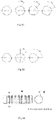
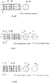
- FIGS. 4A to 4D are diagrams illustrating various shapes and numbers of blending/aligning portions in the metering portion S of the molding screw.
- FIG. 4A includes a side view and an A-A cross-sectional view of a configuration of the metering portion S in which seven blending/aligning portions 40 having the same shape are arranged such that positions of the protrusions and recessions match each other.
- FIG. 4A includes a side view and an A-A cross-sectional view of a configuration of the metering portion S in which seven blending/aligning portions 40 having the same shape are arranged such that positions of the protrusions and recessions match each other.
- FIG. 4B includes a side view and a B-B cross-sectional view of a configuration of the metering portion S in which a total of five blending/aligning portions are provided, including blending/aligning portions 60 and 65 that have different lengths in the screw axis direction and are arranged alternatingly, and the blending/aligning portions are arranged such that positions of the protrusions and recessions match each other.
- FIG. 4C includes a side view, a C-C cross-sectional view, and a D-D cross-sectional view of a configuration of the metering portion S in which seven blending/aligning portions 75 and 80 having different numbers of protrusions and recessions are arranged alternatingly.
- FIG. 4C includes a side view, a C-C cross-sectional view, and a D-D cross-sectional view of a configuration of the metering portion S in which seven blending/aligning portions 75 and 80 having different numbers of protrusions and recessions are
- 4D includes a side view, an E-E cross-sectional view, and an F-F cross-sectional view of a configuration of the metering portion S in which seven blending/aligning portions are provided, including blending/aligning portions 90 and 95 that have the same number of protrusions and recessions but different protrusion/recession heights and that are arranged alternatingly, and the blending/aligning portions are arranged such that positions of the protrusions and recessions match each other.
- sub flight shapes and blending/aligning portions are selected from among the various sub flight shapes and blending/aligning portions shown in FIGS. 3B to 4D in accordance with the molding material, high-quality resin molded articles having little variation can be obtained even if various mixture materials and resin powders are used as the molding material.
- the detailed structures of the sub flights and the blending/aligning portions shown in FIGS. 3B to 4D are described below in working examples.
- the sub flights and the blending/aligning portions shown in FIGS. 3B to 4D are merely examples.
- the polygonal shape of the sub flights is not limited to being a triangular shape or a quadrangular shape, but rather is a concept including polygons with up to eight sides. In the case of a shape that has only two corners, such as an elliptical shape, the distance and region between the cylinder inner wall and the central portion between the corners of the screw are too large. Blending and alignment therefore cannot be performed sufficiently. On the other hand, if the polygonal shape is a shape having more than eight sides, the distance and region between the cylinder inner wall and the central portion between the corners of the screw are too small.
- a molding screw having the following shape can be used.
- Four sub flights are provided, each of which is triangular, and the sub flights have curved surfaces that recede toward the screw axis between the corner portions, and are arranged such that the corner portions are shifted by an angle of 30° each in a view along the screw axis direction.
- the metering portion has a plurality of blending/aligning portions that have the same shape and are arranged such that the protrusions and recessions thereof match each other.
- a screw having the following shape can be used as the molding screw.
- each sub flight has a square shape, and the corners are arranged so that the angles viewed in the screw axis direction are each shifted by an angle of 22.5°.
- the metering portion is constituted by blending/aligning portions that have different lengths in the screw axis direction, the blending alignment portions are arranged such that the lengths thereof are different between adjacent portions, and such that the protrusions and recessions match each other.
- Solid powders made of iron, ceramic, or the like and resin powders have very different specific densities.
- uniform alignment and kneading can be easily performed even when using materials that have very different specific densities. Therefore, variation in the quality of the resin molded body can be reduced, and the proportion of added solid powder such as iron powder can be increased.
- a screw having the following shape can be used as the molding screw.
- each sub flight has a square shape, and the corners are arranged so that the angles viewed in the screw axis direction are each shifted by an angle of 22.5°.
- the metering portion has a plurality of blending/aligning portions that have the same shape and are arranged such that the protrusions and recessions thereof match each other.
- a molding machine screw, an FBI molding machine, and a manufacturing method using the same according to a first working example of the present disclosure are described below with reference to the drawings. First, the molding screw according to this working example and an FBI molding machine using the same will be described.
- FIG. 5A is a schematic side view of the molding screw according to the first working example of the present disclosure.
- FIG. 5B is a cross-sectional view.
- FIG. 6A is a partial diagram showing the configuration of the molding screw in the first working example, and is a cross-sectional view of a feeding portion M.
- FIG. 6B is a partial diagram showing the configuration of the molding screw in the first working example, and is a cross-sectional view of the configuration of a metering portion S and a cross-sectional view in which a protrusion/recession portion is cut at a right angle in the screw axis direction.
- FIG. 7A is an overall schematic perspective view of the molding screw according to the first working example.
- FIG. 7B is an enlarged perspective view of a portion A shown in FIG. 7A .
- FIG. 8A is a diagram showing the shape and arrangement of sub flights of a compressing portion N of the first working example, and is a cross-sectional view showing shift angles of four sub flights.
- FIG. 8B is a diagram showing the shape and arrangement of the sub flights of the compressing portion N of the first working example, and is a cross-sectional view for showing the arrangement of the sub flights as viewed in the screw axis direction.
- FIG. 9A is a diagram showing a state in which a molding material melts and flows in a space between the molding screw 100 and the inner surface of a cylinder 110 in the first working example, and is a schematic diagram in which the compressing portion N has been spread out in the circumferential direction.
- FIG. 9B is a diagram showing a state in which the molding material melts and flows in the first working example, and is data that reveals the flow state of the molding material. In this measurement, a part of the cylinder 110 was formed using a transparent material, and a colored liquid was used instead of the molding material to determine the flow state by image capturing.
- FIG. 10 includes a side view and an A-A cross-sectional view that show the arrangement of blending/aligning portions of the metering portion of the molding screw used in the first working example.
- An FBI molding machine 230 of the present invention has the following configuration as shown in FIG. 1 .
- This machine includes a cylinder 110 in which a heater 120 for heating the interior is arranged, a molding screw 100 rotatably provided in the cylinder 110, and a molding machine hopper 160 for introducing the molding material 220 into the cylinder 110.
- This machine further includes an injection portion 170 that is configured including a driving portion for rotationally driving the molding screw 100 and a back pressure applying portion for applying back pressure for pushing the molding screw toward a mold (not shown).
- a mold (not shown), which has a cavity into which a molding material having increased fluidity is injected, is provided on the leading end portion side of the molding screw 100.
- a cylinder portion 150 includes the cylinder 110, the heater 120, a check valve 130, and the molding screw 100.
- the FBI molding machine 230 also includes a mold clamping device 190 and a safety window 180 to protect the operator from the mold (not shown) portion, and these components are disposed together on a bed 200.
- the machine further includes a kneading portion 210 that includes a metering hopper for metering a mixture material, a resin powder, and an additive, and a mixing drum for mixing and kneading the mixture material, the resin powder, and the additive.
- the kneading portion 210 is constituted by a resin hopper 211 into which the resin powder is introduced, a mixture material hopper 212 into which the mixture material is introduced, a metering hopper 214 for weighing such materials, an additive hopper 213 into which the additive is introduced, and a mixing drum 215.
- the resin powder and the mixture material are introduced into the resin hopper 211 and the mixture material hopper 212 respectively, and are metered by the metering hopper 214.
- the materials are then introduced into the mixing drum 215.
- a required amount of additive is also added from the additive hopper 213.
- These materials are then kneaded by the mixing drum 215. Accordingly, when a molding material 220 is introduced into the molding machine hopper 160, it has been uniformly mixed, and the mixture material and the resin are in an adhered state due to the additive. For this reason, even if the mixture material is solid powder made of iron or ceramic, or reinforcing fiber, more uniform blending, alignment, and kneading can be performed in the molding screw.
- the kneading portion 210 is not essential for the resin molding machine of the present invention, and the mixture material, the resin powder, and the additive (if necessary) may be directly introduced into the molding machine hopper 160.
- the molding screw 100 is for use in the free blend injection molding machine 230 and includes the feeding portion M for feeding the molding material 220 and the compressing portion N and the metering portion S that extend continuously from the feeding portion M, and spiral flights 20 and 30 are respectively formed in the feeding portion M and the compressing portion N.
- the molding screw 100 also includes a shaft portion L having the shaft 10 for connecting the molding screw 100 to the back pressure applying portion and the driving portion in the injection portion 170.
- the flight 30 in the compressing portion N includes four sub flights 31, 32, 33, and 34 in this working example; the sub flights 31, 32, 33, and 34 are triangular with rounded corner portions 31a, 32a, 33a, and 34a; curved surfaces 31c, 32c, 33c, and 34c that are convex toward the screw axis center are formed between the corner portions 31a, 32a, 33a, and 34a; and the corner portions 31a, 32a, 33a, and 34a are arranged shifted by angles of 30° each in a view in the screw axis direction (see FIGS. 7A to 8B ).
- the metering portion S has a configuration including a plurality of blending/aligning portions having gear-like protrusions and recessions in the circumferential direction around the screw axis. Specifically, as shown in FIG. 10 , in the metering portion S, all seven of the blending/aligning portions 40 have the same shape, and recession portions 42 and protrusion portions 41 are arranged so as to match each other in the screw axis direction.
- the following describes functions of the molding screw 100 having such a structure.
- the flight 30 of the compressing portion N has sub flights 31, 32, 33, and 34.
- the sub flights 31, 32, 33, and 34 have corner portions 31a, 32a, 33a, and 34a and curved surfaces 31c, 32c, 33c, and 34c.
- Their overall shape is triangular (rice ball shaped).
- the sub flights 31, 32, 33, and 34 are arranged so that the corner portions 31a, 32a, 33a, and 34a are shifted by an angle of 30° each.
- the corner portions 31a, 32a, 33a, and 34a are regions where the distance from the inner surface of the cylinder 110 is the smallest, and the flow of the molding material 220 is faster in these regions.
- the curved surfaces 31c, 32c, 33c, and 34c are regions where the distance between the inner surface of the cylinder 110 and bottom portions 31b, 32b, 33b, 34b, which are the bottommost portions, is the largest, and the flow of the molding material becomes slower and the kneading becomes stronger upon reaching these regions (see FIGS. 8A to 9B ).
- the following describes a state in which the molding material 220 flows through the sub flights 31, 32, 33, and 34 while the molding screw 100 rotates.
- the molding material 220 flows through the narrow regions at the corner portions 31a, 32a, 33a, and 34a, and then flows into the regions at the curved surfaces 31c, 32c, 33c, and 34c and is kneaded.
- the molding material 220 that has flowed through the large regions at the curved surfaces 31c, 32c, 33c, and 34c then flows into the regions at the corner portions 31a, 32a, 33a, and 34a.
- the flow is faster here.
- the flow slows down, and kneaded is performed.
- the flow of the molding material 220 repeatedly becomes faster and slower.
- the fast-flowing molding material 220 and the slow-flowing molding material 220 are sometimes kneaded together in the regions at the curved surfaces 31c, 32c, 33c, and 34c. As a result, blending, kneading, and alignment proceed.
- FIG. 9B is an actual measurement photograph in which a part of the cylinder 110 was formed using a transparent material, a colored liquid flowed instead of the molding material, and the flow state was measured. Upon observing the flow state of the liquid, it was found that the flow state was close to the schematic diagram shown in FIG. 9A . Accordingly, it was confirmed that with the sub flight configuration of the present disclosure, good blending, alignment, and kneading were performed in the compressing portion N of the molding screw 100.
- the corner portions 31a, 32a, 33a, and 34a are small arcs, the gap regions between the inner surface of the cylinder 110 and the corner portions 31a, 32a, 33a, and 34a are also small. Accordingly, the compression and pressure of the molding material 220 is high in these small regions, and thereafter the molding material 220 flows toward the regions at the curved surfaces 31c, 32c, 33c, and 34c. As a result, even if the included amount of the base resin powder is reduced and the included amount of the mixture material that is a metal or solid powder is increased, it is possible to obtain high-quality resin molded bodies that have little variation in powder mixing.
- thermoplastic resin is generally used as the base resin, and therefore the fluidity increases as the temperature rises, and the fluidity decreases as the temperature falls.
- the molding screw 100 of the present invention when the molding material 220 reaches the regions at the corner portions 31a, 32a, 33a, and 34a, heat from the heater 120 is easily received, and melting is promoted. Also, melting and blending are repeated in the compressing portion N, and therefore the amount of the mixture material in the molding material 220 can be increased.
- the metering portion S is configured including seven blending/aligning portions 40 that have gear-like protrusions and recessions in the circumferential direction around the screw axis.
- the metering portion S all seven of the blending/aligning portions 40 have the same shape, and the recession portions 42 and the protrusion portions 41 are arranged so as to match each other in the screw axis direction.
- the metering portion S is provided with seven blending/aligning portions 40 in order for further uniform alignment in the metering portion S and the nozzle portion connected thereto.
- the blending/aligning portions 40 are each provided with a plurality of arrowhead-shaped protrusion portions 41 in the circumferential direction, and are each shaped like a gear overall.
- the main function of the compressing portion N is to sufficiently blend and knead the molding material to ensure reaction with the additive.
- the main function of the metering portion S is to eliminate variation in (perform alignment of) the composition by overall homogenizing the state in which the mixture material and the resin powder are sufficiently adhered by the additive.
- the compressing portion N and the metering portion S have the above-described structure, in the regions where the distance between the cylinder 110 and the sub flights 31, 32, 33, and 34 is small (in the gaps between the cylinder inner surface and the corner portions 31a, 32a, 33a, and 34a of the sub flights 31, 32, 33, and 34), stronger compressive force acts on the molding material 220, and the molding material 220 moves faster. On the other hand, in the regions where the distance is large (in the gaps between the cylinder inner surface and the bottom portions 31b, 32b, 33b, and 34b of the sub flights 31, 32, 33, and 34), less compressive force acts on the molding material 220, and it moves slower. Due to this repeated fast and slow movement, kneading proceeds further.
- Polypropylene (PP) was used as the resin powder, and glass fiber (GF) having a fiber length of 3 mm was used as the mixture material to make the molding material. Note that an additive and the like were also mixed in.
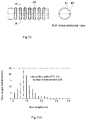
- the molding material was used to manufacture molded bodies using the FBI molding machine of the present invention, and then the fiber length distribution of fibers remaining in the molded bodies was measured. Also, commercially available long-fiber pellets were used to manufacture molded bodies using a conventional injection molding machine, and the fiber length distribution of fibers remaining in the molded bodies was similarly measured. Results of the comparison are shown in FIGS. 11A and 11B .
- FIG. 11A is a fiber length distribution diagram for fibers remaining in molded bodies when the molded bodies were manufactured by a conventional molding machine, and is a comparative example.
- FIG. 11B is a fiber length distribution diagram for fibers remaining in molded bodies when the molded bodies were manufactured by the FBI molding machine of this working example. It can be seen that the proportion of long fibers that remain was large when the FBI molding machine of the present disclosure was used. This is because the proportion of fibers that were broken in the compressing portion and the metering portion of the molding screw was small, and blending and alignment were sufficiently performed. Also, when the molding conditions were determined and continuous molding was performed, the weight variation (3o/weight) per shot could be reduced to 1% or less.
- molded bodies were obtained by performing molding with the FBI molding machine of the present disclosure with use of a molding material containing 34.1% nylon (6PA) and 60% glass fiber (GF), and such molded bodies had a tensile strength of 233 MPa and a tensile modulus of 5280 MPa. This strength could not be obtained for a molded body manufactured using conventional pellets.
- 6PA nylon
- GF 60% glass fiber
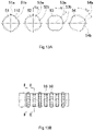
- FIGS. 12A to 12C A molding machine screw, an FBI molding machine, and a manufacturing method using the same according to a second working example of the present disclosure are described below with reference to the drawings.
- FIG. 12A is a diagram showing the shape of the sub flights of the compressing portion according to this working example.
- FIG. 12B is a side view showing the shape of the blending/aligning portions in the metering portion
- FIG. 12C is an A-A cross-sectional view of the blending/aligning portions.
- the sub flights 51, 52, 53, and 54 there are four sub flights 51, 52, 53, and 54 in the compressing portion N of this working example, the sub flights 51, 52, 53, and 54 each have a square shape, and corner portions 51a, 52a, 53a, and 54a are arranged with angles shifted by 22.5° each in a view in the screw axis direction.
- the blending/aligning portions 40 shown in FIGS. 12B and 12C are the same as the blending/aligning portions in the metering portion S according to the first working example, and thus are not described below.
- An FBI molding machine that employs such a molding screw is suitable when using a solid powder in which the mixture material serving as a molding material is a solid.
- the difference in specific gravity between these powders and the resin is large.
- the sub flights have a quadrangular shape, and the number of corner portions is higher.
- a molded body was manufactured using an FBI molding machine provided with this molding screw, and using nylon (6PA) as the resin powder and copper slag powder as the mixture material.
- 6PA nylon
- 46.1% was nylon (6PA)
- 50% was copper slag powder
- the rest was an additive.
- injection molding was performed with an FBI molding machine provided with the molding screw according to this working example.
- the obtained molded product had a specific gravity of 2.79, a tensile strength of 113 MPa, and a Charpy impact strength of 18.5 kJ/m 2 , and it was possible to obtain a copper slag-including resin molded article having a higher strength than a conventional article.
- FIG. 13A is a cross-sectional view showing the shape and arrangement configuration of sub flights of the compressing portion according to this working example.
- FIG. 13B is a side view showing the configuration of the metering portion.
- FIG. 13C is an E-E cross-sectional view and an F-F cross-sectional view of the blending/aligning portions.
- the shape and arrangement of the sub flights 51, 52, 53, and 54 in the compressing portion N shown in FIG. 13A are the same as those of the sub flights in the second working example, and thus are not described below.
- the metering portion S includes a plurality of blending/aligning portions 90 and 95 in which the gear-like protrusions and recessions have different shapes.
- the blending/aligning portions 90 and 95 are alternatingly arranged such that the shapes of the gear-like protrusions and recessions are different in adjacent portions.
- the number of protrusion portions 91 and 96 and the number of recession portions 92 and 97 are both the same in the blending/aligning portions 90 and the blending/aligning portions 95.
- the protrusion portions 96 of the blending/aligning portions 95 are lower than the protrusion portions 91 of the blending/aligning portions 90.
- the blending/aligning portions 90 and the blending/aligning portions 95 are alternatingly arranged at the same distance from each other.
- a molded body was manufactured using an FBI molding machine provided with this molding screw, and using polypropylene (PP) as the resin powder and ceramic powder as the mixture material.
- PP polypropylene
- 46.7% was polypropylene (PP)
- 50.0% was ceramic powder
- the rest was an additive.
- injection molding was performed with an FBI molding machine provided with the molding screw according to this working example.
- the obtained molded product had a specific gravity of 1.27, a tensile strength of 23.5 MPa, and a Charpy impact strength of 15.0 kJ/m 2 , and it was possible to obtain a ceramic powder-including resin molded article that has a higher strength than a conventional product.
- a molding machine screw, an FBI molding machine, and a manufacturing method using the same according to a fourth working example of the present invention are described below with reference to the drawings.
- the FBI molding machine according to this working example is the same as the injection molding machine 230 described in the first working example, and thus is not described below.
- the overall shape of the molding screw is the same as that shown in FIG. 4A . In view of this, the following describes differences from the molding screw 100 according to the first working example.
- FIG. 14A is a cross-sectional view showing the shape and arrangement configuration of sub flights 71, 72, and 73 in the compressing portion according to this working example.
- FIG. 14B is a side view showing the configuration of the metering portion.
- FIG. 14C is a C-C cross-sectional view and a D-D cross-sectional view of the blending/aligning portions.
- sub flights 31, 32, 33, and 34 in the compressing portion N of the molding screw 100 according to the first working example there are four sub flights 31, 32, 33, and 34 in the compressing portion N of the molding screw 100 according to the first working example, each having a triangular shape with rounded corner portions.
- the sub flights 71, 72, and 73 in the compressing portion N according to this working example are also the same in that they have a triangular shape with rounded corner portions. However, three sub flights are provided, and they are shifted by an angle of 45° each.
- the metering portion S is constituted by a plurality of blending/aligning portions 75 and 80 that have different numbers of gear-like protrusions and recessions, and the blending/aligning portions 75 and 80 are alternatingly arranged such that the numbers of gear-like protrusions and recessions are different between adjacent portions.
- the blending/aligning portions 75 are each shaped as a gear that has 20 protrusion portions 76 and 20 recession portions 77.
- the blending/aligning portions 80 are each shaped as a gear that has 10 protrusion portions 81 and 10 recession portions 82.
- the blending/aligning portions 75 and the blending/aligning portions 80 are alternatingly arranged at the same distance from each other.
- the number of protrusion portions is reduced such that the fibers can smoothly flow toward the outlet.
- the number of protrusion portions 81 of the blending/aligning portion 80 is reduced to half in the blending/aligning portions 80, and thus the fibers flow smoothly, and the breakage of the fibers due to rotation of the screw can be suppressed.
- a molded body was manufactured using an FBI molding machine provided with this molding screw, and using nylon (6PA) as the resin powder and glass fiber as the mixture material.
- 6PA nylon
- 34.1% was nylon (6PA)
- 60.0% was glass fiber
- the rest was an additive.
- injection molding was performed with an FBI molding machine provided with the molding screw according to this working example.
- the obtained molded product had a specific gravity of 1.65, a tensile strength of 233 MPa, and a tensile elastic modulus of 5280 MPa, and it was possible to obtain a glass fiber-including resin molded article that has a higher strength than a conventional product.
- a molding machine screw, an FBI molding machine, and a manufacturing method using the same according to a fifth working example of the present invention are described below with reference to the drawings.
- the FBI molding machine according to this working example is the same as the injection molding machine 230 described in the first working example, and thus is not described below.
- the overall shape of the molding screw is the same as that shown in FIG. 4A . In view of this, the following describes differences from the molding screw 100 according to the first working example.
- FIG. 15A is a cross-sectional view showing the shape and arrangement state of sub flights of the compressing portion according to this working example.
- FIG. 15B is a side view showing the configuration of the metering portion.
- FIG. 15C is a B-B cross-sectional view showing the configuration of blending/aligning portions.
- the shape of the sub flights of the compressing portion N shown in FIG. 15A is the same as the shape of the sub flights of the compressing portion N of the molding screw according to the second working example, and thus is not described below.
- the metering portion S is constituted by a plurality of blending/aligning portions 60 and 65 that have different lengths in the screw axis direction.
- the blending/aligning portions are alternatingly arranged such that the lengths are different between adjacent portions.
- the number of protrusion portions 61 and recession portions 62 is the same in the blending/aligning portions 60 and 65, and the protrusion portions 61 and the recession portions 62 are arranged so as to match each other in the screw axis direction.
- a molded body was manufactured using an FBI molding machine provided with this molding screw, and using polypropylene (PP) as the resin powder and glass fiber as the mixture material.
- PP polypropylene
- the molding material 54.1% was polypropylene (PP), 40.0% was glass fiber, and the rest was an additive.
- injection molding was performed with an FBI molding machine provided with the molding screw according to this working example.
- the obtained molded product had a specific gravity of 1.2, a tensile strength of 76 MPa, a tensile elastic modulus of 3120 MPa, and a Charpy impact strength of 30.7 MPa. It was possible to obtain a glass fiber-including resin molded article that has a higher strength than a conventional product, and the resin molded article could replace some metal products.
- the difference between the specific density thereof and the specific density of the resin is significant, and therefore in order to achieve uniform blending and alignment in such a case, the number of protrusion portions may be increased, or the number of blending/aligning portions may be increased.
- the mixture material in the case where wood powder, coffee slag powder, or the like is used as the mixture material, if the mixture material moves slowly in the compressing portion N, overheating and carbonization may occur. However, if the mixture material moves too quickly, it moves to the metering portion S without being blended and kneaded sufficiently, and quality variation of the molded bodies increases. In such a case, the shape of the molding screw is selected such that the molding material flows faster than in the case of using fiber or a metal powder even while being subjected to sufficient compressive force and freed from such compressive force in the compressing portion N. Accordingly, carbonization due to overheating can be suppressed, and molded bodies with stable quality can be manufactured.
- the present invention is not limited to the first to fifth working examples, and as long as the basic configurations of the sub flights of the compressing portion and the blending/aligning portions in the metering portion in the molding screw are the same, the shapes thereof, the number thereof, and the like can be appropriately selected in accordance with the molding material.
- the polygonal shape of the sub flights of the compressing portion is not limited to being triangular or quadrangular, and may also be a polygon having five to eight sides.
- the number of flights of the compressing portion may be increased or decreased in accordance with the molding material.
- the height and shape of the protrusion portions may be changed.
- three or more blending/aligning portions having different protrusion/recession shapes may be included. In this case, it is preferable that adjacent blending/aligning portions have at least different shapes.
- the injection molding screw of the present invention and a resin molding machine using the same are useful in the field of free blend molding, in which various types of resins and organic or inorganic powders are kneaded and directly molded.
Landscapes
- Engineering & Computer Science (AREA)
- Mechanical Engineering (AREA)
- Manufacturing & Machinery (AREA)
- Injection Moulding Of Plastics Or The Like (AREA)
- Processing And Handling Of Plastics And Other Materials For Molding In General (AREA)
Applications Claiming Priority (2)
| Application Number | Priority Date | Filing Date | Title |
|---|---|---|---|
| JP2019185857A JP6971488B2 (ja) | 2019-10-09 | 2019-10-09 | 成形用スクリュー、フリーブレンド方式用射出成形機およびフリーブレンド方式の樹脂成形体製造方法 |
| PCT/JP2020/036829 WO2021070670A1 (fr) | 2019-10-09 | 2020-09-29 | Vis de moulage, machine de moulage par injection pour procédé de mélange libre et procédé de fabrication de corps moulé en résine dans un procédé de mélange libre |
Publications (3)
| Publication Number | Publication Date |
|---|---|
| EP4043177A1 true EP4043177A1 (fr) | 2022-08-17 |
| EP4043177A4 EP4043177A4 (fr) | 2022-12-14 |
| EP4043177B1 EP4043177B1 (fr) | 2023-07-19 |
Family
ID=75379748
Family Applications (1)
| Application Number | Title | Priority Date | Filing Date |
|---|---|---|---|
| EP20874247.8A Active EP4043177B1 (fr) | 2019-10-09 | 2020-09-29 | Vis de moulage, machine de moulage par injection pour procédé de mélange libre et procédé de fabrication de corps moulé en résine dans un procédé de mélange libre |
Country Status (4)
| Country | Link |
|---|---|
| US (1) | US12226940B2 (fr) |
| EP (1) | EP4043177B1 (fr) |
| JP (1) | JP6971488B2 (fr) |
| WO (1) | WO2021070670A1 (fr) |
Families Citing this family (2)
| Publication number | Priority date | Publication date | Assignee | Title |
|---|---|---|---|---|
| KR102915652B1 (ko) * | 2023-01-17 | 2026-01-26 | 주식회사 커피큐브 | 트램형 커피 클레이 제조장치 |
| KR102915651B1 (ko) * | 2023-01-17 | 2026-01-26 | 주식회사 커피큐브 | 엘리베이터형 커피 클레이 제조장치 |
Family Cites Families (18)
| Publication number | Priority date | Publication date | Assignee | Title |
|---|---|---|---|---|
| JPS5328656A (en) * | 1976-08-31 | 1978-03-17 | Ube Industries | Resin molding screw |
| JPS5528816A (en) | 1978-08-21 | 1980-02-29 | Toshiba Mach Co Ltd | Screw for plastic molding apparatus |
| JPS6211612A (ja) * | 1985-07-10 | 1987-01-20 | Toshiba Mach Co Ltd | 射出成形用高混練スクリュ |
| JP3170757B2 (ja) * | 1990-08-31 | 2001-05-28 | 東芝機械株式会社 | バリヤスクリュ |
| JPH06218781A (ja) | 1993-01-26 | 1994-08-09 | Ube Ind Ltd | 射出成形用スクリュ |
| JP3471411B2 (ja) * | 1994-04-06 | 2003-12-02 | 本田技研工業株式会社 | 樹脂成形機用スクリュ |
| JPH0839636A (ja) | 1994-07-29 | 1996-02-13 | Ube Ind Ltd | 可塑化スクリュ |
| JPH08156071A (ja) * | 1994-12-07 | 1996-06-18 | Mitsubishi Heavy Ind Ltd | 押出スクリュ |
| JP2002234063A (ja) | 2001-02-09 | 2002-08-20 | Mitsui Chemicals Inc | 樹脂成形装置および樹脂成形方法ならびにそのための樹脂成形スクリュー |
| JP2002283421A (ja) * | 2001-03-27 | 2002-10-03 | Toray Ind Inc | 繊維強化熱可塑性樹脂の射出成形方法及び成形品 |
| CA2525679C (fr) * | 2003-06-19 | 2007-04-10 | Husky Injection Molding Systems Ltd. | Partie de melange amelioree pour vis de plastification |
| JP2009045745A (ja) * | 2007-08-13 | 2009-03-05 | Teijin Fibers Ltd | ポリエステルの溶融押出機 |
| JP5438843B2 (ja) * | 2010-10-29 | 2014-03-12 | 三菱重工プラスチックテクノロジー株式会社 | 射出成形用可塑化スクリュ及びこれを用いた射出成形方法 |
| EP3200965B1 (fr) * | 2014-09-29 | 2020-09-16 | Compagnie Générale des Etablissements Michelin | Élément de vis d'extrudeuse pour une machine d'extrusion |
| US10766178B2 (en) * | 2015-01-15 | 2020-09-08 | U-Mhi Platech Co., Ltd. | Screw for injection molding machine, injection molding machine, and injection molding method |
| JP6789084B2 (ja) | 2015-11-30 | 2020-11-25 | 東洋機械金属株式会社 | 熱可塑性樹脂と強化用繊維とが混合溶融された溶融樹脂を射出する射出成形機及び射出成形機用スクリュー |
| JP6947522B2 (ja) * | 2017-03-30 | 2021-10-13 | 住友重機械工業株式会社 | 成形機用スクリュ |
| JP2019014115A (ja) * | 2017-07-05 | 2019-01-31 | 株式会社名機製作所 | 可塑化装置の材料供給装置 |
-
2019
- 2019-10-09 JP JP2019185857A patent/JP6971488B2/ja active Active
-
2020
- 2020-09-29 EP EP20874247.8A patent/EP4043177B1/fr active Active
- 2020-09-29 WO PCT/JP2020/036829 patent/WO2021070670A1/fr not_active Ceased
- 2020-09-29 US US17/595,952 patent/US12226940B2/en active Active
Also Published As
| Publication number | Publication date |
|---|---|
| US12226940B2 (en) | 2025-02-18 |
| US20220227033A1 (en) | 2022-07-21 |
| WO2021070670A1 (fr) | 2021-04-15 |
| EP4043177A4 (fr) | 2022-12-14 |
| JP6971488B2 (ja) | 2021-11-24 |
| EP4043177B1 (fr) | 2023-07-19 |
| JP2021059089A (ja) | 2021-04-15 |
Similar Documents
| Publication | Publication Date | Title |
|---|---|---|
| KR102693417B1 (ko) | 재생 탄소 섬유를 함유하는 탄소 섬유 복합 재료, 성형체 및 탄소 섬유 복합 재료의 제조 방법 | |
| EP4043177B1 (fr) | Vis de moulage, machine de moulage par injection pour procédé de mélange libre et procédé de fabrication de corps moulé en résine dans un procédé de mélange libre | |
| JP6789084B2 (ja) | 熱可塑性樹脂と強化用繊維とが混合溶融された溶融樹脂を射出する射出成形機及び射出成形機用スクリュー | |
| KR100927521B1 (ko) | 용융된 폴리머를 압출하는 장치 | |
| EP3922427A1 (fr) | Machine de moulage de composition de résine thermoplastique et procédé de production associé, procédé de fabrication d'article moulé de composition de résine composite, et article moulé par injection | |
| KR101439331B1 (ko) | 복수의 목분투입부와 다단 압출스크류에 의해 제조되는 합성목재 및 그 제조장치 | |
| CN101918185B (zh) | 树脂模制设备 | |
| US5939001A (en) | Process for manufacturing objects from fiber-reinforced thermoplasts | |
| Hornsby | Compounding of particulate-filled thermoplastics | |
| JPH0560780B2 (fr) | ||
| TWI496675B (zh) | Glass fiber reinforced thermoplastic synthetic resin composites for the production of compressed products | |
| JP5032244B2 (ja) | 繊維強化熱可塑性樹脂組成物の製造装置およびその製造方法 | |
| CN201151183Y (zh) | 螺旋芯棒式螺杆混炼头 | |
| JP6167707B2 (ja) | 射出成形装置およびガラス繊維強化樹脂の製造方法 | |
| KR20180009144A (ko) | 재생 pc-abs의 제조방법 및 이에 의해 제조된 재생 pc-abs | |
| Øvrebø et al. | Creating an open-source, low-cost composite feeder design to improve filament quality of high-performance materials to be used in fused filament fabrication (FFF) | |
| WO2017094740A1 (fr) | Machine de moulage par injection et vis de machine de moulage par injection permettant l'injection de résine fondue dans laquelle de la résine thermoplastique et des fibres renforçantes ont été mélangées et la résine a été amenée à fondre | |
| Muralisrinivasan | Introduction to Polymer Compounding: Machinery and Technology, Volume 2 | |
| JP4241556B2 (ja) | ペレット製造方法およびペレット製造装置 | |
| KR102311080B1 (ko) | 폐플라스틱 성분을 활용한 개질아스콘 제조방법 | |
| AU2019232925A1 (en) | Apparatus and method for producing thermoplastic elastomer, elastomers produced thereby and articles produced from the elastomers | |
| JP6816489B2 (ja) | 射出成形品およびその製造方法 | |
| JP2001002929A (ja) | ウッドプラスチック | |
| JPWO2012063298A1 (ja) | 車両構造部材用のまたは航空機構造部材用の樹脂成形品 | |
| JP2007144739A (ja) | 木質系成形体および木質系成形体の製造方法 |
Legal Events
| Date | Code | Title | Description |
|---|---|---|---|
| STAA | Information on the status of an ep patent application or granted ep patent |
Free format text: STATUS: THE INTERNATIONAL PUBLICATION HAS BEEN MADE |
|
| PUAI | Public reference made under article 153(3) epc to a published international application that has entered the european phase |
Free format text: ORIGINAL CODE: 0009012 |
|
| STAA | Information on the status of an ep patent application or granted ep patent |
Free format text: STATUS: REQUEST FOR EXAMINATION WAS MADE |
|
| 17P | Request for examination filed |
Effective date: 20211130 |
|
| AK | Designated contracting states |
Kind code of ref document: A1 Designated state(s): AL AT BE BG CH CY CZ DE DK EE ES FI FR GB GR HR HU IE IS IT LI LT LU LV MC MK MT NL NO PL PT RO RS SE SI SK SM TR |
|
| RIC1 | Information provided on ipc code assigned before grant |
Ipc: B29C 48/655 20190101ALI20221031BHEP Ipc: B29C 48/585 20190101ALI20221031BHEP Ipc: B29C 48/535 20190101ALI20221031BHEP Ipc: B29C 48/395 20190101ALI20221031BHEP Ipc: B29C 48/00 20190101ALI20221031BHEP Ipc: B29B 7/80 20060101ALI20221031BHEP Ipc: B29B 7/42 20060101ALI20221031BHEP Ipc: B29B 7/24 20060101ALI20221031BHEP Ipc: B29B 7/12 20060101ALI20221031BHEP Ipc: B29C 45/50 20060101ALI20221031BHEP Ipc: B29C 45/18 20060101ALI20221031BHEP Ipc: B29C 45/60 20060101AFI20221031BHEP |
|
| A4 | Supplementary search report drawn up and despatched |
Effective date: 20221114 |
|
| RIC1 | Information provided on ipc code assigned before grant |
Ipc: B29C 48/655 20190101ALI20221108BHEP Ipc: B29C 48/585 20190101ALI20221108BHEP Ipc: B29C 48/535 20190101ALI20221108BHEP Ipc: B29C 48/395 20190101ALI20221108BHEP Ipc: B29C 48/00 20190101ALI20221108BHEP Ipc: B29B 7/80 20060101ALI20221108BHEP Ipc: B29B 7/42 20060101ALI20221108BHEP Ipc: B29B 7/24 20060101ALI20221108BHEP Ipc: B29B 7/12 20060101ALI20221108BHEP Ipc: B29C 45/50 20060101ALI20221108BHEP Ipc: B29C 45/18 20060101ALI20221108BHEP Ipc: B29C 45/60 20060101AFI20221108BHEP |
|
| DAV | Request for validation of the european patent (deleted) | ||
| DAX | Request for extension of the european patent (deleted) | ||
| REG | Reference to a national code |
Ref country code: DE Free format text: PREVIOUS MAIN CLASS: B29C0045180000 Ref country code: DE Ref legal event code: R079 Ref document number: 602020014229 Country of ref document: DE Free format text: PREVIOUS MAIN CLASS: B29C0045180000 Ipc: B29C0045600000 |
|
| GRAP | Despatch of communication of intention to grant a patent |
Free format text: ORIGINAL CODE: EPIDOSNIGR1 |
|
| STAA | Information on the status of an ep patent application or granted ep patent |
Free format text: STATUS: GRANT OF PATENT IS INTENDED |
|
| RIC1 | Information provided on ipc code assigned before grant |
Ipc: B29C 45/50 20060101ALI20230330BHEP Ipc: B29C 45/18 20060101ALI20230330BHEP Ipc: B29C 45/60 20060101AFI20230330BHEP |
|
| INTG | Intention to grant announced |
Effective date: 20230418 |
|
| GRAS | Grant fee paid |
Free format text: ORIGINAL CODE: EPIDOSNIGR3 |
|
| GRAA | (expected) grant |
Free format text: ORIGINAL CODE: 0009210 |
|
| STAA | Information on the status of an ep patent application or granted ep patent |
Free format text: STATUS: THE PATENT HAS BEEN GRANTED |
|
| RAP1 | Party data changed (applicant data changed or rights of an application transferred) |
Owner name: DAIICHI SEIKOSHA CO.,LTD. |
|
| AK | Designated contracting states |
Kind code of ref document: B1 Designated state(s): AL AT BE BG CH CY CZ DE DK EE ES FI FR GB GR HR HU IE IS IT LI LT LU LV MC MK MT NL NO PL PT RO RS SE SI SK SM TR |
|
| REG | Reference to a national code |
Ref country code: GB Ref legal event code: FG4D |
|
| REG | Reference to a national code |
Ref country code: CH Ref legal event code: EP |
|
| REG | Reference to a national code |
Ref country code: DE Ref legal event code: R096 Ref document number: 602020014229 Country of ref document: DE |
|
| REG | Reference to a national code |
Ref country code: IE Ref legal event code: FG4D |
|
| REG | Reference to a national code |
Ref country code: LT Ref legal event code: MG9D |
|
| REG | Reference to a national code |
Ref country code: NL Ref legal event code: MP Effective date: 20230719 |
|
| REG | Reference to a national code |
Ref country code: AT Ref legal event code: MK05 Ref document number: 1589020 Country of ref document: AT Kind code of ref document: T Effective date: 20230719 |
|
| PG25 | Lapsed in a contracting state [announced via postgrant information from national office to epo] |
Ref country code: NL Free format text: LAPSE BECAUSE OF FAILURE TO SUBMIT A TRANSLATION OF THE DESCRIPTION OR TO PAY THE FEE WITHIN THE PRESCRIBED TIME-LIMIT Effective date: 20230719 |
|
| PG25 | Lapsed in a contracting state [announced via postgrant information from national office to epo] |
Ref country code: GR Free format text: LAPSE BECAUSE OF FAILURE TO SUBMIT A TRANSLATION OF THE DESCRIPTION OR TO PAY THE FEE WITHIN THE PRESCRIBED TIME-LIMIT Effective date: 20231020 |
|
| PG25 | Lapsed in a contracting state [announced via postgrant information from national office to epo] |
Ref country code: IS Free format text: LAPSE BECAUSE OF FAILURE TO SUBMIT A TRANSLATION OF THE DESCRIPTION OR TO PAY THE FEE WITHIN THE PRESCRIBED TIME-LIMIT Effective date: 20231119 |
|
| PG25 | Lapsed in a contracting state [announced via postgrant information from national office to epo] |
Ref country code: SE Free format text: LAPSE BECAUSE OF FAILURE TO SUBMIT A TRANSLATION OF THE DESCRIPTION OR TO PAY THE FEE WITHIN THE PRESCRIBED TIME-LIMIT Effective date: 20230719 Ref country code: RS Free format text: LAPSE BECAUSE OF FAILURE TO SUBMIT A TRANSLATION OF THE DESCRIPTION OR TO PAY THE FEE WITHIN THE PRESCRIBED TIME-LIMIT Effective date: 20230719 Ref country code: PT Free format text: LAPSE BECAUSE OF FAILURE TO SUBMIT A TRANSLATION OF THE DESCRIPTION OR TO PAY THE FEE WITHIN THE PRESCRIBED TIME-LIMIT Effective date: 20231120 Ref country code: NO Free format text: LAPSE BECAUSE OF FAILURE TO SUBMIT A TRANSLATION OF THE DESCRIPTION OR TO PAY THE FEE WITHIN THE PRESCRIBED TIME-LIMIT Effective date: 20231019 Ref country code: LV Free format text: LAPSE BECAUSE OF FAILURE TO SUBMIT A TRANSLATION OF THE DESCRIPTION OR TO PAY THE FEE WITHIN THE PRESCRIBED TIME-LIMIT Effective date: 20230719 Ref country code: LT Free format text: LAPSE BECAUSE OF FAILURE TO SUBMIT A TRANSLATION OF THE DESCRIPTION OR TO PAY THE FEE WITHIN THE PRESCRIBED TIME-LIMIT Effective date: 20230719 Ref country code: IS Free format text: LAPSE BECAUSE OF FAILURE TO SUBMIT A TRANSLATION OF THE DESCRIPTION OR TO PAY THE FEE WITHIN THE PRESCRIBED TIME-LIMIT Effective date: 20231119 Ref country code: HR Free format text: LAPSE BECAUSE OF FAILURE TO SUBMIT A TRANSLATION OF THE DESCRIPTION OR TO PAY THE FEE WITHIN THE PRESCRIBED TIME-LIMIT Effective date: 20230719 Ref country code: GR Free format text: LAPSE BECAUSE OF FAILURE TO SUBMIT A TRANSLATION OF THE DESCRIPTION OR TO PAY THE FEE WITHIN THE PRESCRIBED TIME-LIMIT Effective date: 20231020 Ref country code: FI Free format text: LAPSE BECAUSE OF FAILURE TO SUBMIT A TRANSLATION OF THE DESCRIPTION OR TO PAY THE FEE WITHIN THE PRESCRIBED TIME-LIMIT Effective date: 20230719 Ref country code: AT Free format text: LAPSE BECAUSE OF FAILURE TO SUBMIT A TRANSLATION OF THE DESCRIPTION OR TO PAY THE FEE WITHIN THE PRESCRIBED TIME-LIMIT Effective date: 20230719 |
|
| PG25 | Lapsed in a contracting state [announced via postgrant information from national office to epo] |
Ref country code: PL Free format text: LAPSE BECAUSE OF FAILURE TO SUBMIT A TRANSLATION OF THE DESCRIPTION OR TO PAY THE FEE WITHIN THE PRESCRIBED TIME-LIMIT Effective date: 20230719 |
|
| REG | Reference to a national code |
Ref country code: DE Ref legal event code: R097 Ref document number: 602020014229 Country of ref document: DE |
|
| PG25 | Lapsed in a contracting state [announced via postgrant information from national office to epo] |
Ref country code: ES Free format text: LAPSE BECAUSE OF FAILURE TO SUBMIT A TRANSLATION OF THE DESCRIPTION OR TO PAY THE FEE WITHIN THE PRESCRIBED TIME-LIMIT Effective date: 20230719 |
|
| PG25 | Lapsed in a contracting state [announced via postgrant information from national office to epo] |
Ref country code: SM Free format text: LAPSE BECAUSE OF FAILURE TO SUBMIT A TRANSLATION OF THE DESCRIPTION OR TO PAY THE FEE WITHIN THE PRESCRIBED TIME-LIMIT Effective date: 20230719 Ref country code: RO Free format text: LAPSE BECAUSE OF FAILURE TO SUBMIT A TRANSLATION OF THE DESCRIPTION OR TO PAY THE FEE WITHIN THE PRESCRIBED TIME-LIMIT Effective date: 20230719 Ref country code: ES Free format text: LAPSE BECAUSE OF FAILURE TO SUBMIT A TRANSLATION OF THE DESCRIPTION OR TO PAY THE FEE WITHIN THE PRESCRIBED TIME-LIMIT Effective date: 20230719 Ref country code: EE Free format text: LAPSE BECAUSE OF FAILURE TO SUBMIT A TRANSLATION OF THE DESCRIPTION OR TO PAY THE FEE WITHIN THE PRESCRIBED TIME-LIMIT Effective date: 20230719 Ref country code: DK Free format text: LAPSE BECAUSE OF FAILURE TO SUBMIT A TRANSLATION OF THE DESCRIPTION OR TO PAY THE FEE WITHIN THE PRESCRIBED TIME-LIMIT Effective date: 20230719 Ref country code: CZ Free format text: LAPSE BECAUSE OF FAILURE TO SUBMIT A TRANSLATION OF THE DESCRIPTION OR TO PAY THE FEE WITHIN THE PRESCRIBED TIME-LIMIT Effective date: 20230719 Ref country code: SK Free format text: LAPSE BECAUSE OF FAILURE TO SUBMIT A TRANSLATION OF THE DESCRIPTION OR TO PAY THE FEE WITHIN THE PRESCRIBED TIME-LIMIT Effective date: 20230719 |
|
| REG | Reference to a national code |
Ref country code: CH Ref legal event code: PL |
|
| PG25 | Lapsed in a contracting state [announced via postgrant information from national office to epo] |
Ref country code: LU Free format text: LAPSE BECAUSE OF NON-PAYMENT OF DUE FEES Effective date: 20230929 |
|
| PLBE | No opposition filed within time limit |
Free format text: ORIGINAL CODE: 0009261 |
|
| STAA | Information on the status of an ep patent application or granted ep patent |
Free format text: STATUS: NO OPPOSITION FILED WITHIN TIME LIMIT |
|
| REG | Reference to a national code |
Ref country code: BE Ref legal event code: MM Effective date: 20230930 |
|
| PG25 | Lapsed in a contracting state [announced via postgrant information from national office to epo] |
Ref country code: LU Free format text: LAPSE BECAUSE OF NON-PAYMENT OF DUE FEES Effective date: 20230929 Ref country code: IT Free format text: LAPSE BECAUSE OF FAILURE TO SUBMIT A TRANSLATION OF THE DESCRIPTION OR TO PAY THE FEE WITHIN THE PRESCRIBED TIME-LIMIT Effective date: 20230719 Ref country code: MC Free format text: LAPSE BECAUSE OF FAILURE TO SUBMIT A TRANSLATION OF THE DESCRIPTION OR TO PAY THE FEE WITHIN THE PRESCRIBED TIME-LIMIT Effective date: 20230719 |
|
| 26N | No opposition filed |
Effective date: 20240422 |
|
| REG | Reference to a national code |
Ref country code: IE Ref legal event code: MM4A |
|
| PG25 | Lapsed in a contracting state [announced via postgrant information from national office to epo] |
Ref country code: IE Free format text: LAPSE BECAUSE OF NON-PAYMENT OF DUE FEES Effective date: 20230929 |
|
| PG25 | Lapsed in a contracting state [announced via postgrant information from national office to epo] |
Ref country code: CH Free format text: LAPSE BECAUSE OF NON-PAYMENT OF DUE FEES Effective date: 20230930 |
|
| PG25 | Lapsed in a contracting state [announced via postgrant information from national office to epo] |
Ref country code: IE Free format text: LAPSE BECAUSE OF NON-PAYMENT OF DUE FEES Effective date: 20230929 Ref country code: CH Free format text: LAPSE BECAUSE OF NON-PAYMENT OF DUE FEES Effective date: 20230930 Ref country code: SI Free format text: LAPSE BECAUSE OF FAILURE TO SUBMIT A TRANSLATION OF THE DESCRIPTION OR TO PAY THE FEE WITHIN THE PRESCRIBED TIME-LIMIT Effective date: 20230719 |
|
| PG25 | Lapsed in a contracting state [announced via postgrant information from national office to epo] |
Ref country code: BE Free format text: LAPSE BECAUSE OF NON-PAYMENT OF DUE FEES Effective date: 20230930 |
|
| PG25 | Lapsed in a contracting state [announced via postgrant information from national office to epo] |
Ref country code: BG Free format text: LAPSE BECAUSE OF FAILURE TO SUBMIT A TRANSLATION OF THE DESCRIPTION OR TO PAY THE FEE WITHIN THE PRESCRIBED TIME-LIMIT Effective date: 20230719 |
|
| PG25 | Lapsed in a contracting state [announced via postgrant information from national office to epo] |
Ref country code: BG Free format text: LAPSE BECAUSE OF FAILURE TO SUBMIT A TRANSLATION OF THE DESCRIPTION OR TO PAY THE FEE WITHIN THE PRESCRIBED TIME-LIMIT Effective date: 20230719 |
|
| GBPC | Gb: european patent ceased through non-payment of renewal fee |
Effective date: 20240929 |
|
| PG25 | Lapsed in a contracting state [announced via postgrant information from national office to epo] |
Ref country code: GB Free format text: LAPSE BECAUSE OF NON-PAYMENT OF DUE FEES Effective date: 20240929 |
|
| PG25 | Lapsed in a contracting state [announced via postgrant information from national office to epo] |
Ref country code: CY Free format text: LAPSE BECAUSE OF FAILURE TO SUBMIT A TRANSLATION OF THE DESCRIPTION OR TO PAY THE FEE WITHIN THE PRESCRIBED TIME-LIMIT; INVALID AB INITIO Effective date: 20200929 |
|
| PG25 | Lapsed in a contracting state [announced via postgrant information from national office to epo] |
Ref country code: HU Free format text: LAPSE BECAUSE OF FAILURE TO SUBMIT A TRANSLATION OF THE DESCRIPTION OR TO PAY THE FEE WITHIN THE PRESCRIBED TIME-LIMIT; INVALID AB INITIO Effective date: 20200929 |
|
| PGFP | Annual fee paid to national office [announced via postgrant information from national office to epo] |
Ref country code: DE Payment date: 20250919 Year of fee payment: 6 |
|
| PGFP | Annual fee paid to national office [announced via postgrant information from national office to epo] |
Ref country code: FR Payment date: 20250820 Year of fee payment: 6 |
|
| PG25 | Lapsed in a contracting state [announced via postgrant information from national office to epo] |
Ref country code: TR Free format text: LAPSE BECAUSE OF FAILURE TO SUBMIT A TRANSLATION OF THE DESCRIPTION OR TO PAY THE FEE WITHIN THE PRESCRIBED TIME-LIMIT Effective date: 20230719 |