EP4043257A2 - Fahrzeugsteuerungsvorrichtung und fahrzeugsteuerungsverfahren - Google Patents
Fahrzeugsteuerungsvorrichtung und fahrzeugsteuerungsverfahren Download PDFInfo
- Publication number
- EP4043257A2 EP4043257A2 EP22152721.1A EP22152721A EP4043257A2 EP 4043257 A2 EP4043257 A2 EP 4043257A2 EP 22152721 A EP22152721 A EP 22152721A EP 4043257 A2 EP4043257 A2 EP 4043257A2
- Authority
- EP
- European Patent Office
- Prior art keywords
- driving
- electric power
- amount
- restricted
- vehicle
- Prior art date
- Legal status (The legal status is an assumption and is not a legal conclusion. Google has not performed a legal analysis and makes no representation as to the accuracy of the status listed.)
- Pending
Links
Images


Classifications
-
- B—PERFORMING OPERATIONS; TRANSPORTING
- B60—VEHICLES IN GENERAL
- B60K—ARRANGEMENT OR MOUNTING OF PROPULSION UNITS OR OF TRANSMISSIONS IN VEHICLES; ARRANGEMENT OR MOUNTING OF PLURAL DIVERSE PRIME-MOVERS IN VEHICLES; AUXILIARY DRIVES FOR VEHICLES; INSTRUMENTATION OR DASHBOARDS FOR VEHICLES; ARRANGEMENTS IN CONNECTION WITH COOLING, AIR INTAKE, GAS EXHAUST OR FUEL SUPPLY OF PROPULSION UNITS IN VEHICLES
- B60K6/00—Arrangement or mounting of plural diverse prime-movers for mutual or common propulsion, e.g. hybrid propulsion systems comprising electric motors and internal combustion engines
- B60K6/20—Arrangement or mounting of plural diverse prime-movers for mutual or common propulsion, e.g. hybrid propulsion systems comprising electric motors and internal combustion engines the prime-movers consisting of electric motors and internal combustion engines, e.g. HEVs
- B60K6/42—Arrangement or mounting of plural diverse prime-movers for mutual or common propulsion, e.g. hybrid propulsion systems comprising electric motors and internal combustion engines the prime-movers consisting of electric motors and internal combustion engines, e.g. HEVs characterised by the architecture of the hybrid electric vehicle
- B60K6/44—Series-parallel type
- B60K6/445—Differential gearing distribution type
-
- B—PERFORMING OPERATIONS; TRANSPORTING
- B60—VEHICLES IN GENERAL
- B60W—CONJOINT CONTROL OF VEHICLE SUB-UNITS OF DIFFERENT TYPE OR DIFFERENT FUNCTION; CONTROL SYSTEMS SPECIALLY ADAPTED FOR HYBRID VEHICLES; ROAD VEHICLE DRIVE CONTROL SYSTEMS FOR PURPOSES NOT RELATED TO THE CONTROL OF A PARTICULAR SUB-UNIT
- B60W20/00—Control systems specially adapted for hybrid vehicles
- B60W20/40—Controlling the engagement or disengagement of prime movers, e.g. for transition between prime movers
-
- B—PERFORMING OPERATIONS; TRANSPORTING
- B60—VEHICLES IN GENERAL
- B60K—ARRANGEMENT OR MOUNTING OF PROPULSION UNITS OR OF TRANSMISSIONS IN VEHICLES; ARRANGEMENT OR MOUNTING OF PLURAL DIVERSE PRIME-MOVERS IN VEHICLES; AUXILIARY DRIVES FOR VEHICLES; INSTRUMENTATION OR DASHBOARDS FOR VEHICLES; ARRANGEMENTS IN CONNECTION WITH COOLING, AIR INTAKE, GAS EXHAUST OR FUEL SUPPLY OF PROPULSION UNITS IN VEHICLES
- B60K35/00—Instruments specially adapted for vehicles; Arrangement of instruments in or on vehicles
- B60K35/10—Input arrangements, i.e. from user to vehicle, associated with vehicle functions or specially adapted therefor
-
- B—PERFORMING OPERATIONS; TRANSPORTING
- B60—VEHICLES IN GENERAL
- B60K—ARRANGEMENT OR MOUNTING OF PROPULSION UNITS OR OF TRANSMISSIONS IN VEHICLES; ARRANGEMENT OR MOUNTING OF PLURAL DIVERSE PRIME-MOVERS IN VEHICLES; AUXILIARY DRIVES FOR VEHICLES; INSTRUMENTATION OR DASHBOARDS FOR VEHICLES; ARRANGEMENTS IN CONNECTION WITH COOLING, AIR INTAKE, GAS EXHAUST OR FUEL SUPPLY OF PROPULSION UNITS IN VEHICLES
- B60K35/00—Instruments specially adapted for vehicles; Arrangement of instruments in or on vehicles
- B60K35/20—Output arrangements, i.e. from vehicle to user, associated with vehicle functions or specially adapted therefor
- B60K35/28—Output arrangements, i.e. from vehicle to user, associated with vehicle functions or specially adapted therefor characterised by the type of the output information, e.g. video entertainment or vehicle dynamics information; characterised by the purpose of the output information, e.g. for attracting the attention of the driver
-
- B—PERFORMING OPERATIONS; TRANSPORTING
- B60—VEHICLES IN GENERAL
- B60K—ARRANGEMENT OR MOUNTING OF PROPULSION UNITS OR OF TRANSMISSIONS IN VEHICLES; ARRANGEMENT OR MOUNTING OF PLURAL DIVERSE PRIME-MOVERS IN VEHICLES; AUXILIARY DRIVES FOR VEHICLES; INSTRUMENTATION OR DASHBOARDS FOR VEHICLES; ARRANGEMENTS IN CONNECTION WITH COOLING, AIR INTAKE, GAS EXHAUST OR FUEL SUPPLY OF PROPULSION UNITS IN VEHICLES
- B60K35/00—Instruments specially adapted for vehicles; Arrangement of instruments in or on vehicles
- B60K35/60—Instruments characterised by their location or relative disposition in or on vehicles
-
- B—PERFORMING OPERATIONS; TRANSPORTING
- B60—VEHICLES IN GENERAL
- B60K—ARRANGEMENT OR MOUNTING OF PROPULSION UNITS OR OF TRANSMISSIONS IN VEHICLES; ARRANGEMENT OR MOUNTING OF PLURAL DIVERSE PRIME-MOVERS IN VEHICLES; AUXILIARY DRIVES FOR VEHICLES; INSTRUMENTATION OR DASHBOARDS FOR VEHICLES; ARRANGEMENTS IN CONNECTION WITH COOLING, AIR INTAKE, GAS EXHAUST OR FUEL SUPPLY OF PROPULSION UNITS IN VEHICLES
- B60K35/00—Instruments specially adapted for vehicles; Arrangement of instruments in or on vehicles
- B60K35/80—Arrangements for controlling instruments
-
- B—PERFORMING OPERATIONS; TRANSPORTING
- B60—VEHICLES IN GENERAL
- B60L—PROPULSION OF ELECTRICALLY-PROPELLED VEHICLES; SUPPLYING ELECTRIC POWER FOR AUXILIARY EQUIPMENT OF ELECTRICALLY-PROPELLED VEHICLES; ELECTRODYNAMIC BRAKE SYSTEMS FOR VEHICLES IN GENERAL; MAGNETIC SUSPENSION OR LEVITATION FOR VEHICLES; MONITORING OPERATING VARIABLES OF ELECTRICALLY-PROPELLED VEHICLES; ELECTRIC SAFETY DEVICES FOR ELECTRICALLY-PROPELLED VEHICLES
- B60L50/00—Electric propulsion with power supplied within the vehicle
- B60L50/10—Electric propulsion with power supplied within the vehicle using propulsion power supplied by engine-driven generators, e.g. generators driven by combustion engines
- B60L50/16—Electric propulsion with power supplied within the vehicle using propulsion power supplied by engine-driven generators, e.g. generators driven by combustion engines with provision for separate direct mechanical propulsion
-
- B—PERFORMING OPERATIONS; TRANSPORTING
- B60—VEHICLES IN GENERAL
- B60L—PROPULSION OF ELECTRICALLY-PROPELLED VEHICLES; SUPPLYING ELECTRIC POWER FOR AUXILIARY EQUIPMENT OF ELECTRICALLY-PROPELLED VEHICLES; ELECTRODYNAMIC BRAKE SYSTEMS FOR VEHICLES IN GENERAL; MAGNETIC SUSPENSION OR LEVITATION FOR VEHICLES; MONITORING OPERATING VARIABLES OF ELECTRICALLY-PROPELLED VEHICLES; ELECTRIC SAFETY DEVICES FOR ELECTRICALLY-PROPELLED VEHICLES
- B60L50/00—Electric propulsion with power supplied within the vehicle
- B60L50/50—Electric propulsion with power supplied within the vehicle using propulsion power supplied by batteries or fuel cells
- B60L50/60—Electric propulsion with power supplied within the vehicle using propulsion power supplied by batteries or fuel cells using power supplied by batteries
-
- B—PERFORMING OPERATIONS; TRANSPORTING
- B60—VEHICLES IN GENERAL
- B60L—PROPULSION OF ELECTRICALLY-PROPELLED VEHICLES; SUPPLYING ELECTRIC POWER FOR AUXILIARY EQUIPMENT OF ELECTRICALLY-PROPELLED VEHICLES; ELECTRODYNAMIC BRAKE SYSTEMS FOR VEHICLES IN GENERAL; MAGNETIC SUSPENSION OR LEVITATION FOR VEHICLES; MONITORING OPERATING VARIABLES OF ELECTRICALLY-PROPELLED VEHICLES; ELECTRIC SAFETY DEVICES FOR ELECTRICALLY-PROPELLED VEHICLES
- B60L53/00—Methods of charging batteries, specially adapted for electric vehicles; Charging stations or on-board charging equipment therefor; Exchange of energy storage elements in electric vehicles
- B60L53/30—Constructional details of charging stations
- B60L53/305—Communication interfaces
-
- B—PERFORMING OPERATIONS; TRANSPORTING
- B60—VEHICLES IN GENERAL
- B60L—PROPULSION OF ELECTRICALLY-PROPELLED VEHICLES; SUPPLYING ELECTRIC POWER FOR AUXILIARY EQUIPMENT OF ELECTRICALLY-PROPELLED VEHICLES; ELECTRODYNAMIC BRAKE SYSTEMS FOR VEHICLES IN GENERAL; MAGNETIC SUSPENSION OR LEVITATION FOR VEHICLES; MONITORING OPERATING VARIABLES OF ELECTRICALLY-PROPELLED VEHICLES; ELECTRIC SAFETY DEVICES FOR ELECTRICALLY-PROPELLED VEHICLES
- B60L53/00—Methods of charging batteries, specially adapted for electric vehicles; Charging stations or on-board charging equipment therefor; Exchange of energy storage elements in electric vehicles
- B60L53/50—Charging stations characterised by energy-storage or power-generation means
- B60L53/51—Photovoltaic means
-
- B—PERFORMING OPERATIONS; TRANSPORTING
- B60—VEHICLES IN GENERAL
- B60L—PROPULSION OF ELECTRICALLY-PROPELLED VEHICLES; SUPPLYING ELECTRIC POWER FOR AUXILIARY EQUIPMENT OF ELECTRICALLY-PROPELLED VEHICLES; ELECTRODYNAMIC BRAKE SYSTEMS FOR VEHICLES IN GENERAL; MAGNETIC SUSPENSION OR LEVITATION FOR VEHICLES; MONITORING OPERATING VARIABLES OF ELECTRICALLY-PROPELLED VEHICLES; ELECTRIC SAFETY DEVICES FOR ELECTRICALLY-PROPELLED VEHICLES
- B60L58/00—Methods or circuit arrangements for monitoring or controlling batteries or fuel cells, specially adapted for electric vehicles
- B60L58/10—Methods or circuit arrangements for monitoring or controlling batteries or fuel cells, specially adapted for electric vehicles for monitoring or controlling batteries
- B60L58/12—Methods or circuit arrangements for monitoring or controlling batteries or fuel cells, specially adapted for electric vehicles for monitoring or controlling batteries responding to state of charge [SoC]
-
- B—PERFORMING OPERATIONS; TRANSPORTING
- B60—VEHICLES IN GENERAL
- B60L—PROPULSION OF ELECTRICALLY-PROPELLED VEHICLES; SUPPLYING ELECTRIC POWER FOR AUXILIARY EQUIPMENT OF ELECTRICALLY-PROPELLED VEHICLES; ELECTRODYNAMIC BRAKE SYSTEMS FOR VEHICLES IN GENERAL; MAGNETIC SUSPENSION OR LEVITATION FOR VEHICLES; MONITORING OPERATING VARIABLES OF ELECTRICALLY-PROPELLED VEHICLES; ELECTRIC SAFETY DEVICES FOR ELECTRICALLY-PROPELLED VEHICLES
- B60L7/00—Electrodynamic brake systems for vehicles in general
- B60L7/10—Dynamic electric regenerative braking
-
- B—PERFORMING OPERATIONS; TRANSPORTING
- B60—VEHICLES IN GENERAL
- B60L—PROPULSION OF ELECTRICALLY-PROPELLED VEHICLES; SUPPLYING ELECTRIC POWER FOR AUXILIARY EQUIPMENT OF ELECTRICALLY-PROPELLED VEHICLES; ELECTRODYNAMIC BRAKE SYSTEMS FOR VEHICLES IN GENERAL; MAGNETIC SUSPENSION OR LEVITATION FOR VEHICLES; MONITORING OPERATING VARIABLES OF ELECTRICALLY-PROPELLED VEHICLES; ELECTRIC SAFETY DEVICES FOR ELECTRICALLY-PROPELLED VEHICLES
- B60L8/00—Electric propulsion with power supply from forces of nature, e.g. sun or wind
- B60L8/003—Converting light into electric energy, e.g. by using photo-voltaic systems
-
- B—PERFORMING OPERATIONS; TRANSPORTING
- B60—VEHICLES IN GENERAL
- B60W—CONJOINT CONTROL OF VEHICLE SUB-UNITS OF DIFFERENT TYPE OR DIFFERENT FUNCTION; CONTROL SYSTEMS SPECIALLY ADAPTED FOR HYBRID VEHICLES; ROAD VEHICLE DRIVE CONTROL SYSTEMS FOR PURPOSES NOT RELATED TO THE CONTROL OF A PARTICULAR SUB-UNIT
- B60W10/00—Conjoint control of vehicle sub-units of different type or different function
- B60W10/04—Conjoint control of vehicle sub-units of different type or different function including control of propulsion units
- B60W10/06—Conjoint control of vehicle sub-units of different type or different function including control of propulsion units including control of combustion engines
-
- B—PERFORMING OPERATIONS; TRANSPORTING
- B60—VEHICLES IN GENERAL
- B60W—CONJOINT CONTROL OF VEHICLE SUB-UNITS OF DIFFERENT TYPE OR DIFFERENT FUNCTION; CONTROL SYSTEMS SPECIALLY ADAPTED FOR HYBRID VEHICLES; ROAD VEHICLE DRIVE CONTROL SYSTEMS FOR PURPOSES NOT RELATED TO THE CONTROL OF A PARTICULAR SUB-UNIT
- B60W10/00—Conjoint control of vehicle sub-units of different type or different function
- B60W10/04—Conjoint control of vehicle sub-units of different type or different function including control of propulsion units
- B60W10/08—Conjoint control of vehicle sub-units of different type or different function including control of propulsion units including control of electric propulsion units, e.g. motors or generators
-
- B—PERFORMING OPERATIONS; TRANSPORTING
- B60—VEHICLES IN GENERAL
- B60W—CONJOINT CONTROL OF VEHICLE SUB-UNITS OF DIFFERENT TYPE OR DIFFERENT FUNCTION; CONTROL SYSTEMS SPECIALLY ADAPTED FOR HYBRID VEHICLES; ROAD VEHICLE DRIVE CONTROL SYSTEMS FOR PURPOSES NOT RELATED TO THE CONTROL OF A PARTICULAR SUB-UNIT
- B60W20/00—Control systems specially adapted for hybrid vehicles
- B60W20/10—Controlling the power contribution of each of the prime movers to meet required power demand
- B60W20/12—Controlling the power contribution of each of the prime movers to meet required power demand using control strategies taking into account route information
-
- B—PERFORMING OPERATIONS; TRANSPORTING
- B60—VEHICLES IN GENERAL
- B60W—CONJOINT CONTROL OF VEHICLE SUB-UNITS OF DIFFERENT TYPE OR DIFFERENT FUNCTION; CONTROL SYSTEMS SPECIALLY ADAPTED FOR HYBRID VEHICLES; ROAD VEHICLE DRIVE CONTROL SYSTEMS FOR PURPOSES NOT RELATED TO THE CONTROL OF A PARTICULAR SUB-UNIT
- B60W20/00—Control systems specially adapted for hybrid vehicles
- B60W20/10—Controlling the power contribution of each of the prime movers to meet required power demand
- B60W20/13—Controlling the power contribution of each of the prime movers to meet required power demand in order to stay within battery power input or output limits; in order to prevent overcharging or battery depletion
- B60W20/14—Controlling the power contribution of each of the prime movers to meet required power demand in order to stay within battery power input or output limits; in order to prevent overcharging or battery depletion in conjunction with braking regeneration
-
- B—PERFORMING OPERATIONS; TRANSPORTING
- B60—VEHICLES IN GENERAL
- B60W—CONJOINT CONTROL OF VEHICLE SUB-UNITS OF DIFFERENT TYPE OR DIFFERENT FUNCTION; CONTROL SYSTEMS SPECIALLY ADAPTED FOR HYBRID VEHICLES; ROAD VEHICLE DRIVE CONTROL SYSTEMS FOR PURPOSES NOT RELATED TO THE CONTROL OF A PARTICULAR SUB-UNIT
- B60W20/00—Control systems specially adapted for hybrid vehicles
- B60W20/10—Controlling the power contribution of each of the prime movers to meet required power demand
- B60W20/15—Control strategies specially adapted for achieving a particular effect
- B60W20/16—Control strategies specially adapted for achieving a particular effect for reducing engine exhaust emissions
-
- B—PERFORMING OPERATIONS; TRANSPORTING
- B60—VEHICLES IN GENERAL
- B60W—CONJOINT CONTROL OF VEHICLE SUB-UNITS OF DIFFERENT TYPE OR DIFFERENT FUNCTION; CONTROL SYSTEMS SPECIALLY ADAPTED FOR HYBRID VEHICLES; ROAD VEHICLE DRIVE CONTROL SYSTEMS FOR PURPOSES NOT RELATED TO THE CONTROL OF A PARTICULAR SUB-UNIT
- B60W20/00—Control systems specially adapted for hybrid vehicles
- B60W20/20—Control strategies involving selection of hybrid configuration, e.g. selection between series or parallel configuration
-
- B—PERFORMING OPERATIONS; TRANSPORTING
- B60—VEHICLES IN GENERAL
- B60W—CONJOINT CONTROL OF VEHICLE SUB-UNITS OF DIFFERENT TYPE OR DIFFERENT FUNCTION; CONTROL SYSTEMS SPECIALLY ADAPTED FOR HYBRID VEHICLES; ROAD VEHICLE DRIVE CONTROL SYSTEMS FOR PURPOSES NOT RELATED TO THE CONTROL OF A PARTICULAR SUB-UNIT
- B60W30/00—Purposes of road vehicle drive control systems not related to the control of a particular sub-unit, e.g. of systems using conjoint control of vehicle sub-units
- B60W30/18—Propelling the vehicle
- B60W30/18009—Propelling the vehicle related to particular drive situations
- B60W30/18109—Braking
- B60W30/18127—Regenerative braking
-
- B—PERFORMING OPERATIONS; TRANSPORTING
- B60—VEHICLES IN GENERAL
- B60W—CONJOINT CONTROL OF VEHICLE SUB-UNITS OF DIFFERENT TYPE OR DIFFERENT FUNCTION; CONTROL SYSTEMS SPECIALLY ADAPTED FOR HYBRID VEHICLES; ROAD VEHICLE DRIVE CONTROL SYSTEMS FOR PURPOSES NOT RELATED TO THE CONTROL OF A PARTICULAR SUB-UNIT
- B60W50/00—Details of control systems for road vehicle drive control not related to the control of a particular sub-unit, e.g. process diagnostic or vehicle driver interfaces
- B60W50/0097—Predicting future conditions
-
- B—PERFORMING OPERATIONS; TRANSPORTING
- B60—VEHICLES IN GENERAL
- B60W—CONJOINT CONTROL OF VEHICLE SUB-UNITS OF DIFFERENT TYPE OR DIFFERENT FUNCTION; CONTROL SYSTEMS SPECIALLY ADAPTED FOR HYBRID VEHICLES; ROAD VEHICLE DRIVE CONTROL SYSTEMS FOR PURPOSES NOT RELATED TO THE CONTROL OF A PARTICULAR SUB-UNIT
- B60W50/00—Details of control systems for road vehicle drive control not related to the control of a particular sub-unit, e.g. process diagnostic or vehicle driver interfaces
- B60W50/08—Interaction between the driver and the control system
- B60W50/14—Means for informing the driver, warning the driver or prompting a driver intervention
-
- G—PHYSICS
- G01—MEASURING; TESTING
- G01C—MEASURING DISTANCES, LEVELS OR BEARINGS; SURVEYING; NAVIGATION; GYROSCOPIC INSTRUMENTS; PHOTOGRAMMETRY OR VIDEOGRAMMETRY
- G01C21/00—Navigation; Navigational instruments not provided for in groups G01C1/00 - G01C19/00
- G01C21/26—Navigation; Navigational instruments not provided for in groups G01C1/00 - G01C19/00 specially adapted for navigation in a road network
- G01C21/34—Route searching; Route guidance
- G01C21/3407—Route searching; Route guidance specially adapted for specific applications
- G01C21/3415—Dynamic re-routing, e.g. recalculating the route when the user deviates from calculated route or after detecting real-time traffic data or accidents
-
- G—PHYSICS
- G01—MEASURING; TESTING
- G01C—MEASURING DISTANCES, LEVELS OR BEARINGS; SURVEYING; NAVIGATION; GYROSCOPIC INSTRUMENTS; PHOTOGRAMMETRY OR VIDEOGRAMMETRY
- G01C21/00—Navigation; Navigational instruments not provided for in groups G01C1/00 - G01C19/00
- G01C21/26—Navigation; Navigational instruments not provided for in groups G01C1/00 - G01C19/00 specially adapted for navigation in a road network
- G01C21/34—Route searching; Route guidance
- G01C21/3407—Route searching; Route guidance specially adapted for specific applications
- G01C21/343—Calculating itineraries
-
- G—PHYSICS
- G01—MEASURING; TESTING
- G01C—MEASURING DISTANCES, LEVELS OR BEARINGS; SURVEYING; NAVIGATION; GYROSCOPIC INSTRUMENTS; PHOTOGRAMMETRY OR VIDEOGRAMMETRY
- G01C21/00—Navigation; Navigational instruments not provided for in groups G01C1/00 - G01C19/00
- G01C21/26—Navigation; Navigational instruments not provided for in groups G01C1/00 - G01C19/00 specially adapted for navigation in a road network
- G01C21/34—Route searching; Route guidance
- G01C21/3453—Special cost functions, i.e. other than distance or default speed limit of road segments
- G01C21/3469—Fuel consumption; Energy use; Emission aspects
-
- B—PERFORMING OPERATIONS; TRANSPORTING
- B60—VEHICLES IN GENERAL
- B60K—ARRANGEMENT OR MOUNTING OF PROPULSION UNITS OR OF TRANSMISSIONS IN VEHICLES; ARRANGEMENT OR MOUNTING OF PLURAL DIVERSE PRIME-MOVERS IN VEHICLES; AUXILIARY DRIVES FOR VEHICLES; INSTRUMENTATION OR DASHBOARDS FOR VEHICLES; ARRANGEMENTS IN CONNECTION WITH COOLING, AIR INTAKE, GAS EXHAUST OR FUEL SUPPLY OF PROPULSION UNITS IN VEHICLES
- B60K2360/00—Indexing scheme associated with groups B60K35/00 or B60K37/00 relating to details of instruments or dashboards
- B60K2360/16—Type of output information
- B60K2360/166—Navigation
-
- B—PERFORMING OPERATIONS; TRANSPORTING
- B60—VEHICLES IN GENERAL
- B60K—ARRANGEMENT OR MOUNTING OF PROPULSION UNITS OR OF TRANSMISSIONS IN VEHICLES; ARRANGEMENT OR MOUNTING OF PLURAL DIVERSE PRIME-MOVERS IN VEHICLES; AUXILIARY DRIVES FOR VEHICLES; INSTRUMENTATION OR DASHBOARDS FOR VEHICLES; ARRANGEMENTS IN CONNECTION WITH COOLING, AIR INTAKE, GAS EXHAUST OR FUEL SUPPLY OF PROPULSION UNITS IN VEHICLES
- B60K2360/00—Indexing scheme associated with groups B60K35/00 or B60K37/00 relating to details of instruments or dashboards
- B60K2360/16—Type of output information
- B60K2360/169—Remaining operating distance or charge
-
- B—PERFORMING OPERATIONS; TRANSPORTING
- B60—VEHICLES IN GENERAL
- B60K—ARRANGEMENT OR MOUNTING OF PROPULSION UNITS OR OF TRANSMISSIONS IN VEHICLES; ARRANGEMENT OR MOUNTING OF PLURAL DIVERSE PRIME-MOVERS IN VEHICLES; AUXILIARY DRIVES FOR VEHICLES; INSTRUMENTATION OR DASHBOARDS FOR VEHICLES; ARRANGEMENTS IN CONNECTION WITH COOLING, AIR INTAKE, GAS EXHAUST OR FUEL SUPPLY OF PROPULSION UNITS IN VEHICLES
- B60K6/00—Arrangement or mounting of plural diverse prime-movers for mutual or common propulsion, e.g. hybrid propulsion systems comprising electric motors and internal combustion engines
- B60K6/20—Arrangement or mounting of plural diverse prime-movers for mutual or common propulsion, e.g. hybrid propulsion systems comprising electric motors and internal combustion engines the prime-movers consisting of electric motors and internal combustion engines, e.g. HEVs
- B60K6/22—Arrangement or mounting of plural diverse prime-movers for mutual or common propulsion, e.g. hybrid propulsion systems comprising electric motors and internal combustion engines the prime-movers consisting of electric motors and internal combustion engines, e.g. HEVs characterised by apparatus, components or means specially adapted for HEVs
- B60K6/24—Arrangement or mounting of plural diverse prime-movers for mutual or common propulsion, e.g. hybrid propulsion systems comprising electric motors and internal combustion engines the prime-movers consisting of electric motors and internal combustion engines, e.g. HEVs characterised by apparatus, components or means specially adapted for HEVs characterised by the combustion engines
-
- B—PERFORMING OPERATIONS; TRANSPORTING
- B60—VEHICLES IN GENERAL
- B60L—PROPULSION OF ELECTRICALLY-PROPELLED VEHICLES; SUPPLYING ELECTRIC POWER FOR AUXILIARY EQUIPMENT OF ELECTRICALLY-PROPELLED VEHICLES; ELECTRODYNAMIC BRAKE SYSTEMS FOR VEHICLES IN GENERAL; MAGNETIC SUSPENSION OR LEVITATION FOR VEHICLES; MONITORING OPERATING VARIABLES OF ELECTRICALLY-PROPELLED VEHICLES; ELECTRIC SAFETY DEVICES FOR ELECTRICALLY-PROPELLED VEHICLES
- B60L2240/00—Control parameters of input or output; Target parameters
- B60L2240/10—Vehicle control parameters
- B60L2240/12—Speed
-
- B—PERFORMING OPERATIONS; TRANSPORTING
- B60—VEHICLES IN GENERAL
- B60L—PROPULSION OF ELECTRICALLY-PROPELLED VEHICLES; SUPPLYING ELECTRIC POWER FOR AUXILIARY EQUIPMENT OF ELECTRICALLY-PROPELLED VEHICLES; ELECTRODYNAMIC BRAKE SYSTEMS FOR VEHICLES IN GENERAL; MAGNETIC SUSPENSION OR LEVITATION FOR VEHICLES; MONITORING OPERATING VARIABLES OF ELECTRICALLY-PROPELLED VEHICLES; ELECTRIC SAFETY DEVICES FOR ELECTRICALLY-PROPELLED VEHICLES
- B60L2240/00—Control parameters of input or output; Target parameters
- B60L2240/60—Navigation input
- B60L2240/62—Vehicle position
- B60L2240/622—Vehicle position by satellite navigation
-
- B—PERFORMING OPERATIONS; TRANSPORTING
- B60—VEHICLES IN GENERAL
- B60L—PROPULSION OF ELECTRICALLY-PROPELLED VEHICLES; SUPPLYING ELECTRIC POWER FOR AUXILIARY EQUIPMENT OF ELECTRICALLY-PROPELLED VEHICLES; ELECTRODYNAMIC BRAKE SYSTEMS FOR VEHICLES IN GENERAL; MAGNETIC SUSPENSION OR LEVITATION FOR VEHICLES; MONITORING OPERATING VARIABLES OF ELECTRICALLY-PROPELLED VEHICLES; ELECTRIC SAFETY DEVICES FOR ELECTRICALLY-PROPELLED VEHICLES
- B60L2240/00—Control parameters of input or output; Target parameters
- B60L2240/60—Navigation input
- B60L2240/66—Ambient conditions
- B60L2240/662—Temperature
-
- B—PERFORMING OPERATIONS; TRANSPORTING
- B60—VEHICLES IN GENERAL
- B60L—PROPULSION OF ELECTRICALLY-PROPELLED VEHICLES; SUPPLYING ELECTRIC POWER FOR AUXILIARY EQUIPMENT OF ELECTRICALLY-PROPELLED VEHICLES; ELECTRODYNAMIC BRAKE SYSTEMS FOR VEHICLES IN GENERAL; MAGNETIC SUSPENSION OR LEVITATION FOR VEHICLES; MONITORING OPERATING VARIABLES OF ELECTRICALLY-PROPELLED VEHICLES; ELECTRIC SAFETY DEVICES FOR ELECTRICALLY-PROPELLED VEHICLES
- B60L2240/00—Control parameters of input or output; Target parameters
- B60L2240/60—Navigation input
- B60L2240/66—Ambient conditions
- B60L2240/667—Precipitation
-
- B—PERFORMING OPERATIONS; TRANSPORTING
- B60—VEHICLES IN GENERAL
- B60L—PROPULSION OF ELECTRICALLY-PROPELLED VEHICLES; SUPPLYING ELECTRIC POWER FOR AUXILIARY EQUIPMENT OF ELECTRICALLY-PROPELLED VEHICLES; ELECTRODYNAMIC BRAKE SYSTEMS FOR VEHICLES IN GENERAL; MAGNETIC SUSPENSION OR LEVITATION FOR VEHICLES; MONITORING OPERATING VARIABLES OF ELECTRICALLY-PROPELLED VEHICLES; ELECTRIC SAFETY DEVICES FOR ELECTRICALLY-PROPELLED VEHICLES
- B60L2240/00—Control parameters of input or output; Target parameters
- B60L2240/70—Interactions with external data bases, e.g. traffic centres
- B60L2240/72—Charging station selection relying on external data
-
- B—PERFORMING OPERATIONS; TRANSPORTING
- B60—VEHICLES IN GENERAL
- B60L—PROPULSION OF ELECTRICALLY-PROPELLED VEHICLES; SUPPLYING ELECTRIC POWER FOR AUXILIARY EQUIPMENT OF ELECTRICALLY-PROPELLED VEHICLES; ELECTRODYNAMIC BRAKE SYSTEMS FOR VEHICLES IN GENERAL; MAGNETIC SUSPENSION OR LEVITATION FOR VEHICLES; MONITORING OPERATING VARIABLES OF ELECTRICALLY-PROPELLED VEHICLES; ELECTRIC SAFETY DEVICES FOR ELECTRICALLY-PROPELLED VEHICLES
- B60L2250/00—Driver interactions
- B60L2250/12—Driver interactions by confirmation, e.g. of the input
-
- B—PERFORMING OPERATIONS; TRANSPORTING
- B60—VEHICLES IN GENERAL
- B60L—PROPULSION OF ELECTRICALLY-PROPELLED VEHICLES; SUPPLYING ELECTRIC POWER FOR AUXILIARY EQUIPMENT OF ELECTRICALLY-PROPELLED VEHICLES; ELECTRODYNAMIC BRAKE SYSTEMS FOR VEHICLES IN GENERAL; MAGNETIC SUSPENSION OR LEVITATION FOR VEHICLES; MONITORING OPERATING VARIABLES OF ELECTRICALLY-PROPELLED VEHICLES; ELECTRIC SAFETY DEVICES FOR ELECTRICALLY-PROPELLED VEHICLES
- B60L2250/00—Driver interactions
- B60L2250/16—Driver interactions by display
-
- B—PERFORMING OPERATIONS; TRANSPORTING
- B60—VEHICLES IN GENERAL
- B60L—PROPULSION OF ELECTRICALLY-PROPELLED VEHICLES; SUPPLYING ELECTRIC POWER FOR AUXILIARY EQUIPMENT OF ELECTRICALLY-PROPELLED VEHICLES; ELECTRODYNAMIC BRAKE SYSTEMS FOR VEHICLES IN GENERAL; MAGNETIC SUSPENSION OR LEVITATION FOR VEHICLES; MONITORING OPERATING VARIABLES OF ELECTRICALLY-PROPELLED VEHICLES; ELECTRIC SAFETY DEVICES FOR ELECTRICALLY-PROPELLED VEHICLES
- B60L2260/00—Operating Modes
- B60L2260/40—Control modes
- B60L2260/50—Control modes by future state prediction
- B60L2260/54—Energy consumption estimation
-
- B—PERFORMING OPERATIONS; TRANSPORTING
- B60—VEHICLES IN GENERAL
- B60W—CONJOINT CONTROL OF VEHICLE SUB-UNITS OF DIFFERENT TYPE OR DIFFERENT FUNCTION; CONTROL SYSTEMS SPECIALLY ADAPTED FOR HYBRID VEHICLES; ROAD VEHICLE DRIVE CONTROL SYSTEMS FOR PURPOSES NOT RELATED TO THE CONTROL OF A PARTICULAR SUB-UNIT
- B60W50/00—Details of control systems for road vehicle drive control not related to the control of a particular sub-unit, e.g. process diagnostic or vehicle driver interfaces
- B60W50/08—Interaction between the driver and the control system
- B60W50/14—Means for informing the driver, warning the driver or prompting a driver intervention
- B60W2050/146—Display means
-
- B—PERFORMING OPERATIONS; TRANSPORTING
- B60—VEHICLES IN GENERAL
- B60W—CONJOINT CONTROL OF VEHICLE SUB-UNITS OF DIFFERENT TYPE OR DIFFERENT FUNCTION; CONTROL SYSTEMS SPECIALLY ADAPTED FOR HYBRID VEHICLES; ROAD VEHICLE DRIVE CONTROL SYSTEMS FOR PURPOSES NOT RELATED TO THE CONTROL OF A PARTICULAR SUB-UNIT
- B60W2510/00—Input parameters relating to a particular sub-units
- B60W2510/24—Energy storage means
- B60W2510/242—Energy storage means for electrical energy
- B60W2510/244—Charge state
-
- B—PERFORMING OPERATIONS; TRANSPORTING
- B60—VEHICLES IN GENERAL
- B60W—CONJOINT CONTROL OF VEHICLE SUB-UNITS OF DIFFERENT TYPE OR DIFFERENT FUNCTION; CONTROL SYSTEMS SPECIALLY ADAPTED FOR HYBRID VEHICLES; ROAD VEHICLE DRIVE CONTROL SYSTEMS FOR PURPOSES NOT RELATED TO THE CONTROL OF A PARTICULAR SUB-UNIT
- B60W2555/00—Input parameters relating to exterior conditions, not covered by groups B60W2552/00, B60W2554/00
- B60W2555/20—Ambient conditions, e.g. wind or rain
-
- B—PERFORMING OPERATIONS; TRANSPORTING
- B60—VEHICLES IN GENERAL
- B60W—CONJOINT CONTROL OF VEHICLE SUB-UNITS OF DIFFERENT TYPE OR DIFFERENT FUNCTION; CONTROL SYSTEMS SPECIALLY ADAPTED FOR HYBRID VEHICLES; ROAD VEHICLE DRIVE CONTROL SYSTEMS FOR PURPOSES NOT RELATED TO THE CONTROL OF A PARTICULAR SUB-UNIT
- B60W2555/00—Input parameters relating to exterior conditions, not covered by groups B60W2552/00, B60W2554/00
- B60W2555/60—Traffic rules, e.g. speed limits or right of way
-
- B—PERFORMING OPERATIONS; TRANSPORTING
- B60—VEHICLES IN GENERAL
- B60W—CONJOINT CONTROL OF VEHICLE SUB-UNITS OF DIFFERENT TYPE OR DIFFERENT FUNCTION; CONTROL SYSTEMS SPECIALLY ADAPTED FOR HYBRID VEHICLES; ROAD VEHICLE DRIVE CONTROL SYSTEMS FOR PURPOSES NOT RELATED TO THE CONTROL OF A PARTICULAR SUB-UNIT
- B60W2556/00—Input parameters relating to data
- B60W2556/10—Historical data
-
- B—PERFORMING OPERATIONS; TRANSPORTING
- B60—VEHICLES IN GENERAL
- B60W—CONJOINT CONTROL OF VEHICLE SUB-UNITS OF DIFFERENT TYPE OR DIFFERENT FUNCTION; CONTROL SYSTEMS SPECIALLY ADAPTED FOR HYBRID VEHICLES; ROAD VEHICLE DRIVE CONTROL SYSTEMS FOR PURPOSES NOT RELATED TO THE CONTROL OF A PARTICULAR SUB-UNIT
- B60W2556/00—Input parameters relating to data
- B60W2556/45—External transmission of data to or from the vehicle
- B60W2556/50—External transmission of data to or from the vehicle of positioning data, e.g. GPS [Global Positioning System] data
-
- B—PERFORMING OPERATIONS; TRANSPORTING
- B60—VEHICLES IN GENERAL
- B60W—CONJOINT CONTROL OF VEHICLE SUB-UNITS OF DIFFERENT TYPE OR DIFFERENT FUNCTION; CONTROL SYSTEMS SPECIALLY ADAPTED FOR HYBRID VEHICLES; ROAD VEHICLE DRIVE CONTROL SYSTEMS FOR PURPOSES NOT RELATED TO THE CONTROL OF A PARTICULAR SUB-UNIT
- B60W2710/00—Output or target parameters relating to a particular sub-units
- B60W2710/24—Energy storage means
- B60W2710/242—Energy storage means for electrical energy
- B60W2710/244—Charge state
-
- B—PERFORMING OPERATIONS; TRANSPORTING
- B60—VEHICLES IN GENERAL
- B60Y—INDEXING SCHEME RELATING TO ASPECTS CROSS-CUTTING VEHICLE TECHNOLOGY
- B60Y2400/00—Special features of vehicle units
- B60Y2400/21—External power supplies
- B60Y2400/214—External power supplies by power from domestic supply, e.g. plug in supplies
-
- B—PERFORMING OPERATIONS; TRANSPORTING
- B60—VEHICLES IN GENERAL
- B60Y—INDEXING SCHEME RELATING TO ASPECTS CROSS-CUTTING VEHICLE TECHNOLOGY
- B60Y2400/00—Special features of vehicle units
- B60Y2400/21—External power supplies
- B60Y2400/216—External power supplies by solar panels
Definitions
- the present invention relates to a vehicle control device and vehicle control method.
- Japanese Unexamined Patent Publication No. 2019-151316 discloses a conventional control device of a vehicle configured so as to prepare a driving plan dividing a projected route from a starting point to a destination into a plurality of sections and classifying the sections into EV sections for driving in the EV mode and HV sections for driving in the HV mode.
- the present invention was made focusing on such a problem and has as its object to prepare a suitable driving plan considering restricted regions.
- a vehicle control device for controlling a vehicle equipped with an internal combustion engine, rotating electric machine, and battery.
- the vehicle control device is provided with a driving plan preparation part for preparing a driving plan dividing a scheduled driving route up to a destination of the vehicle into a plurality of driving sections and setting which driving mode the driving sections should be driven in between an EV mode stopping the operation of the internal combustion engine and driving by the drive power of the rotating electric machine and an HV mode running by drive power of the internal combustion engine and the drive power of the rotating electric machine and a drive power control part for controlling the internal combustion engine and rotating electric machine based on the driving plan, the driving plan preparation part configured so that, when driving sections are present inside a restricted region, it extracts as a restricted driving section from among driving sections present inside the restricted region a driving section through which it is projected the vehicle will be driven in a restricted time period in which operation of internal combustion engines is restricted and prepares a driving plan able to drive through the restricted driving section
- a vehicle control device for controlling a vehicle equipped with an internal combustion engine configured to be able to burn hydrogen fuel in part of the cylinders and able to burn a fossil fuel in the remaining cylinders.
- the vehicle control device comprises a driving plan preparation part for preparing a driving plan dividing a scheduled driving route up to a destination of the vehicle into a plurality of driving sections and setting which driving mode the driving sections should be driven in between a first mode running by burning only hydrogen fuel or a second mode running by burning at least fossil fuel and a drive power control part for controlling the internal combustion engine based on the driving plan, the driving plan preparation part configured so that, when driving sections are present inside a restricted region, it extracts as a restricted driving section from among driving sections present inside the restricted region a driving section through which it is projected that the vehicle will be driven in a restricted time period in which burning fossil fuel to operate internal combustion engines is restricted and prepares a driving plan able to drive through the restricted driving section in the first mode.
- a vehicle control method for controlling a vehicle equipped with an internal combustion engine, rotating electric machine, and battery.
- the vehicle control method according to the present aspect includes a step of dividing a scheduled driving route up to a destination of the vehicle into a plurality of driving sections and setting which driving mode the driving sections should be driven in between an EV mode stopping the operation of the internal combustion engine and driving by the drive power of the rotating electric machine and an HV mode running by drive power of the internal combustion engine and the drive power of the rotating electric machine.
- This step further includes a step of judging if driving sections are present inside a restricted region, a step where, when driving sections are present inside a restricted region, it extracts as a restricted driving section from among driving sections present inside the restricted region a driving section through which it is projected the vehicle will be driven in a restricted time period in which operation of internal combustion engines is restricted, and a step of setting the driving mode of the restricted driving section to the EV mode.
- the vehicle control system 100 As shown in FIG. 1 , the vehicle control system 100 according to the present embodiment is provided with a server 1 and a vehicle 2.
- the server 1 is provided with a server communication part 11, server storage part 12, and server processing part 13.
- the server communication part 11 has a communication interface circuit for connecting the server 1 through for example a gateway etc. to a network 3 and is configured to be able to communicate with the vehicle 2.
- the server storage part 12 stores at least information relating to restricted regions established at different places in a country (information relating to later explained boundaries GF or restricted time periods etc.).
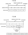
- a "restricted region” is a region in which operation of internal combustion engines is restricted from the viewpoint of prevention of air pollution, the viewpoint of noise prevention, or other viewpoints. If simply explaining a restricted region while referring to FIG. 2, FIG. 2 shows the boundary GF between the inside and outside of the restricted region and road positions Kd, Ke, Kf, Kg on the boundary GF.
- the inside of the boundary GF is the restricted region.
- this restricted region is for example a restricted region of a variable time period type established only for a predetermined restricted time period, operation of internal combustion engines inside the restricted region is restricted for only the restricted time period while operation of internal combustion engines is allowed in the nonrestricted time period.
- the restricted time period is, for example, set in units of hours, days, weeks, months, years, days of the week, etc.
- the restricted region shown in FIG. 2 is a fixed type restricted region in which no restricted time period is particularly established, operation of internal combustion engines is restricted at all times inside the restricted region.
- gates are provided.
- a signal notifying the vehicle 2 that it has entered the restricted region from the gate is sent.
- the vehicle 2 receives this signal and recognizes that the host vehicle has entered inside the restricted region, it automatically restricts operation of the internal combustion engine mounted in the host vehicle (for example, if the vehicle 2 is a hybrid vehicle, the driving mode is automatically made the EV mode).
- the server processing part 13 has one or more processors and their peripheral circuits.
- the server processing part 13 runs various computer programs stored in the server storage part 12 and comprehensively controls the overall operation of the server 1 and is, for example, a CPU (central processing unit).
- FIG. 3 is a schematic view of the configuration of the vehicle 2.
- the hybrid system 21 is provided with an internal combustion engine 211, drive power splitting mechanism 212, first rotating electric machine 213 used mainly as a generator, second rotating electric machine 214 used mainly as a motor, battery 215, and power control unit (below, referred to as a "PCU") 216.
- PCU power control unit
- the internal combustion engine 211 burns fuel inside the cylinders formed at the inside and generates drive power for making an engine output shaft coupled with the drive power splitting mechanism 212 rotate.
- the internal combustion engine 211 according to the present embodiment is a gasoline engine burning gasoline fuel to generate drive power.
- the drive power splitting mechanism 212 is a known planetary gear mechanism dividing the drive power of the internal combustion engine 211 into the two systems of drive power for making the driving wheels turn and drive power for driving regenerative operation of the first rotating electric machine 213.
- the first rotating electric machine 213 is, for example, a three-phase alternating current synchronous type of motor-generator and has a function as a motor receiving the supply of electric power from the battery 215 to drive a power operation and a function as a generator receiving drive power of the internal combustion engine 211 to drive a regenerative operation.
- the first rotating electric machine 213 is mainly used as a generator and generates the electric power required for charging the battery 215 and the electric power required for driving regenerative operation of the second rotating electric machine 214. Further, it is used as a motor when making the engine output shaft rotate for cranking at the time of startup of the internal combustion engine 211 and performs the role of a starter.
- the battery 215 is, for example, a nickel cadmium storage battery or nickel hydrogen storage battery, lithium ion battery, or other rechargeable secondary battery.
- the battery 215 is electrically connected through the PCU 216 to the first rotating electric machine 213 and the second rotating electric machine 214 so as to be able to supply the charged electric power of the battery 215 to the first rotating electric machine 213 and the second rotating electric machine 214 to drive a power operation and, further, so as to be able to charge the battery 215 with generated electric power of the first rotating electric machine 213 and the second rotating electric machine 214.
- the battery 215 is configured to be able to be electrically connected at the home or a charging station etc. through a charging control circuit 217 and charging lid 218 to an outside power source so as to enable charging from the outside power source.
- the charging control circuit 217 is an electrical circuit which can convert the alternating current supplied from the outside power source to a direct current and boost the input voltage to the battery voltage to charge the electric power of the outside power source at the battery 215 based on control signals from the electronic control unit 20.
- the GPS receiving device 22 receives radio waves from satellites to identify the latitude and longitude of the hybrid vehicle 2 and detect the current position of the vehicle 2.
- the map information storage device 23 stores position information of the roads, information on the road shapes (for example, the road grades, curves or straight sections, curvature of curves, etc.), position information of intersections and branch points, road types, speed limits, and other map information.
- the communication device 24 is a vehicle-mounted terminal having a wireless communication function.
- the communication device 24 accesses a wireless base station 4 (see FIG. 1 ) connected with a network 3 (see FIG. 1 ) through a not shown gateway etc. to be connected through the wireless base station 4 with the network 3. Due to this, two-way communication with the server 1 is performed.
- the HMI device 25 is an interface for transfer of information with the vehicle occupants.
- the HMI device 25 according to the present embodiment is provided with a display and speaker for providing the vehicle occupants with various types of information and a touch panel for a vehicle occupant to operate to enter information.
- the HMI device 25 sends the input information which was inputted by the vehicle occupant (for example, the destination, waypoints, and other information) to the electronic control unit 20 and the navigation device 26. Further, when receiving various types of information from the electronic control unit 20 or navigation device 26, outside information receiving device 27, etc., the HMI device 25 displays the received information on the display etc. to provide it to the vehicle occupants.
- the outside information receiving device 27 receives outside information sent from a road traffic information communication system center or other outside communication center.
- the outside information is, for example, congestion information or accident information or other road traffic information or meteorological information (rain or snow, fog, wind speed, temperature, humidity, or other information) etc.
- the outside information receiving device 27 sends the received outside information to the electronic control unit 20.
- the SOC sensor 28a detects the amount of electric power Wn[kWh] of the current charged in the battery 215 (below, referred to as the "amount of battery electric power").
- the load sensor 28b detects an output voltage proportional to the amount of depression of the accelerator pedal as a parameter corresponding to the driving load.
- the vehicle speed sensor 28c detects the speed of the vehicle 2.
- the electronic control unit 20 is provided with an internal vehicle communication interface 201, vehicle storage part 202, and vehicle processing part 203.
- the internal vehicle communication interface 201, the vehicle storage part 202, and the vehicle processing part 203 are connected to each other through signal wires.
- the internal vehicle communication interface 201 is a communication interface circuit for connecting the electronic control unit 20 to an internal vehicle network 29 based on the CAN (Controller Area Network) or other standard.
- CAN Controller Area Network
- the vehicle storage part 202 has an HDD (hard disk drive) or optical recording medium, semiconductor memory, or other storage medium and stores various types of computer programs or data etc. used for processing at the vehicle processing part 203.
- HDD hard disk drive
- optical recording medium semiconductor memory, or other storage medium
- the vehicle processing part 203 has one or more processors and their peripheral circuits.
- the vehicle processing part 203 runs computer programs stored at the vehicle storage part 202 to comprehensively control the vehicle 2 and is, for example, a CPU.
- the content of the control relating to mainly the preparation of a driving plan in the various control of the vehicle 2 performed by the vehicle processing part 203 and in turn the electronic control unit 20 will be explained.
- the electronic control unit 20 switches the driving mode to either the EV (electric vehicle) mode or HV (hybrid vehicle) mode to make the vehicle 2 run.
- EV electric vehicle
- HV hybrid vehicle
- the EV mode is a mode where the electric power of the battery 215 is utilized with priority so as to drive a power operation of the second rotating electric machine 214 to consume the electric power of the battery 215 and transmits the drive power of the second rotating electric machine 214 to the driving wheels to make the vehicle 2 run. Therefore, the EV mode is sometimes also called a "CD (charge depleting) mode".
- CD charge depleting
- the electronic control unit 20 basically uses the electric power of the battery 215 in a state making the internal combustion engine 211 stop to drive a power operation of the second rotating electric machine 214 and makes the driving wheels rotate to make the vehicle 2 run by only the drive power of the second rotating electric machine 214.
- the HV mode is a mode where the outputs of the internal combustion engine 211 and the second rotating electric machine 214 are controlled to make the vehicle 2 run so that the amount of battery electric power is maintained at the amount of electric power when switched to the HV mode (below, referred to as the "amount of sustained electric power"). Therefore, the HV mode is sometimes referred to as the "CS (charge sustaining) mode".
- the electronic control unit 20 uses the electric power of the battery 215 in a state making the internal combustion engine 211 stop to drive a power operation of the second rotating electric machine 214 and makes the driving wheels rotate to make the vehicle 2 run by only the drive power of the second rotating electric machine 214. Note that the electronic control unit 20, as shown in FIG. 5 , makes the switching load change in accordance with the amount of battery electric power so that the switching load becomes smaller the smaller the amount of battery electric power.
- the electronic control unit 20 splits the drive power of the internal combustion engine 211 by the drive power splitting mechanism 212 into two systems, transmits one split drive power of the internal combustion engine 211 to the driving wheels, and uses the other drive power to drive regenerative operation of the first rotating electric machine 213. Further, while using the generated electric power of the first rotating electric machine 213 to drive power operation of the second rotating electric machine 214, in accordance with need, part of the generated electric power is supplied to the battery 215 to charge the battery and, in addition to part of the drive power of the internal combustion engine 211, the drive power of the second rotating electric machine 214 is transmitted to the driving wheels to make the vehicle 2 run.
- the driving mode is preferably set to the EV mode to make the vehicle 2 run. Further, when the driving section is one where steady driving where greater than or equal to a certain constant vehicle speed is maintained or otherwise the driving section is one with driving in a region of engine load with a good heat efficiency, the driving mode is preferably set to the HV mode to make the vehicle 2 run.
- preparing a driving plan splitting the scheduled driving route from the starting point (current position) to the destination into a plurality of driving section and designating which driving sections to be run in the EV mode and which driving sections to be run in the HV section based on map information of the driving sections (for example, the driving loads or other road information etc.) and switching the driving modes while running the vehicle 2 in accordance with the driving plan can be said to be an effective method for keeping down the amount of fuel consumption.
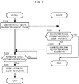
- FIG. 7 is a flow chart for explaining control for acquiring restricted region information according to the present embodiment.
- the electronic control unit 20 repeatedly performs the present routine at predetermined processing cycles.
- the electronic control unit 20 of the vehicle 2 sends a restricted region information request signal to the server 1 to acquire the restricted region information.
- the restricted region information request signal includes at least an identification number of the host vehicle stored in advance in the vehicle storage part 202 (for example the vehicle license plate number) and the scheduled driving route of the host vehicle.
- the restricted region information is information including information relating to whether there is restricted region on the scheduled driving route, information on the boundary GF or restricted time period of the restricted region if there is a restricted region on the scheduled driving route, etc.
- the server 1 judges whether it has received a restricted region information request signal. If it has received a restricted region information request signal, the server 1 proceeds to the processing of step S3. On the other hand, if it has not received a restricted region information request signal, the server 1 ends the current processing.
- the server 1 generates the restricted region information and sends it to the vehicle 2 originally sending the restricted region information request signal (below, in accordance with need, also referred to as the "sending vehicle 2".
- the server 1 first judges if there is a restricted region present on the scheduled driving route of the sending vehicle 2 based on the information relating to restricted regions stored in the server storage part 12 and the scheduled driving route of the sending vehicle 2. Further, if there is not a restricted region present on the scheduled driving route of the sending vehicle 2, the server 1 generates restricted region information including information to that effect and sends it to the sending vehicle 2. On the other hand, if there is a restricted region present on the scheduled driving route of the sending vehicle 2, the server 1 generates restricted region information including information relating to the boundary GF and restricted time period of that restricted region and sends it to the sending vehicle 2.
- step S104 the electronic control unit 20 of the vehicle 2 judges if it has received the restricted region information. If it has received the restricted region information, the electronic control unit 20 proceeds to the processing of step S5. On the other hand, if it has not received the restricted region information, the electronic control unit 20 waits for a certain time, then again judges if it has received the restricted region information.
- the electronic control unit 20 of the vehicle 2 stores the content of the received restricted region information in the vehicle storage part 202 and updates the content of the restricted region information.
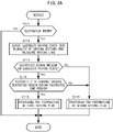
- FIG. 8A is a flow chart for explaining control for preparing a driving plan according to the present embodiment.
- the electronic control unit 20 repeatedly performs the present routine at a predetermined processing cycle.
- the electronic control unit 20 of the vehicle 2 judges if the destination is known.
- the destination may be a destination input through the HMI device 25 by a vehicle occupant or for example may be a destination surmised based on the past driving history of the vehicle 2 etc. If the destination is known, the electronic control unit 20 proceeds to the processing of step S112. On the other hand, if the destination is not known, the electronic control unit 20 ends the current processing without preparing a driving plan.
- the electronic control unit 20 of the vehicle 2 divides the scheduled driving route into a plurality of driving sections and calculates the driving loads of the driving sections based on the map information.
- the electronic control unit 20 of the vehicle 2 calculates the projected driving time ranges of the driving sections on the scheduled driving route based on the current time, map information, and outside information (road traffic information). Further, the electronic control unit 20 judges if among the driving sections present inside a restricted region, there is a driving section where the projected driving time range overlaps the restricted time period of that restricted region (below, referred to as a "restricted driving section"). If there is a restricted driving section, the electronic control unit 20 judges that there is a possibility of running through the inside of the restricted region during the restricted time period and proceeds to the processing of step S115. On the other hand, if there is no restricted driving section, the electronic control unit 20 judges that there is no possibility of running through the inside of the restricted region during the restricted time period and proceeds to the processing of step S116.
- step S116 the electronic control unit 20 of the vehicle 2 performs processing for preparation of a second driving plan for preparing a normal driving plan not considering restricted regions (below, referred to as the "second driving plan"). Details of the processing for preparation of a second driving plan will be explained later referring to FIG. 8C .
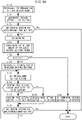
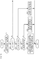
- FIG. 8B is a flow chart explaining details of the processing for preparation of a first driving plan.
- the electronic control unit 20 of the vehicle 2 sets the restricted driving section as an EV section for running in the EV mode.
- step S122 the electronic control unit 20 of the vehicle 2 judges if there is any driving section for which the driving mode has not been set. If there is a driving section for which the driving mode has not been set, the electronic control unit 20 proceeds to the processing of step S123. On the other hand, if there is no driving section for which the driving mode has not been set, the electronic control unit 20 ends the preparation of the first driving plan.
- the electronic control unit 20 of the vehicle 2 calculates the estimated value W1[kWh] of the amount of electric power consumed when running through all of the restricted driving sections in the EV mode based on the driving loads of the restricted driving sections (the amount of electric power consumed for driving the second rotating electric machine 214 and the amount of electric power consumed by vehicle-mounted equipment other than the second rotating electric machine 214) (below, referred to as the "first estimated amount of electric power").
- the electronic control unit 20 of the vehicle 2 calculates the amount of battery electric power WA[kWh] able to be used in the remaining driving sections other than the restricted driving sections in the current amount of battery electric power Wn detected by the SOC sensor 28a (below, referred to as the "amount of available battery electric power").
- the electronic control unit 20 calculates the remaining amount of electric power obtained by subtracting from the current amount of battery electric power Wn the first estimated amount of electric power W1 as the amount of available battery electric power WA.
- the electronic control unit 20 of the vehicle 2 calculates the EV suitabilities of the remaining driving sections based on the driving loads of the remaining driving sections other than the restricted driving sections on the scheduled driving route.
- the EV suitability is an indicator showing by which extent each driving section is suitable for EV driving. In the present embodiment, the lower the driving load of the driving section, the higher the value (that is, the more suitable for EV driving).
- step S127 the electronic control unit 20 of the vehicle 2 sets the driving section with the highest EV suitability among the driving sections for which the driving mode has not been set as the "driving mode setting section".
- step S1208 the electronic control unit 20 of the vehicle 2 judges if it is possible to set the driving mode setting section as an EV section.
- the electronic control unit 20 first calculates the estimated value W2[kWh] of the amount of electric power consumed when driving through the driving mode setting section in the EV mode (below, referred to as the "second estimated amount of electric power ”) based on the driving load of the driving mode setting section.
- the electronic control unit 20 judges if the amount of available battery electric power WA is greater than or equal to the third estimated amount of electric power W3. That is, the electronic control unit 20 judges if the amount of available battery electric power WA is greater than or equal to the amount of electric power enough for enabling the driving mode setting section to be newly set as an EV section in addition to the driving sections already set as EV sections. If the amount of available battery electric power WA is greater than or equal to the third estimated amount of electric power W3, the electronic control unit 20 judges that the driving mode setting section can be newly set as an EV section and proceeds to the processing of step S129. On the other hand, if the amount of available battery electric power WA is less than the third estimated amount of electric power W3, the electronic control unit 20 judges that the driving mode setting section cannot be set as an EV section and proceeds to the processing of step S130.
- the electronic control unit 20 of the vehicle 2 sets the driving mode setting section as an EV section.
- the electronic control unit 20 of the vehicle 2 sets the driving mode setting section as an HV section.
- step S131 the electronic control unit 20 of the vehicle 2 judges if there is any driving section for which the driving mode has not been set.
- the electronic control unit 20 returns again to step S127 if there is a driving section for which the driving mode has not been set and sets the driving mode for the driving section for which the driving mode has not been set.
- the electronic control unit 20 ends the preparation of the first driving plan.
- the electronic control unit 20 of the vehicle 2 sets the driving modes of all of the remaining driving sections for which the driving mode has still not yet been set, including the driving mode setting section, as HV sections.
- the driving modes of the driving sections it is also possible to determine the driving modes of the driving sections, then decide at which of the HV sections among them the drive power of the internal combustion engine 211 should be used to enable part of the generated electric power generated at the first rotating electric machine 213 to be supplied to the battery 215 to charge the battery 215. If using the drive power of the internal combustion engine 211 to charge the battery 215, the load of the internal combustion engine 211 increases by exactly the amount generating electric power for charging the battery 215. For this reason, if charging the battery 215 in the low load side engine operation region, the noise of the internal combustion engine 211 is liable to increase along with the increase in load of the internal combustion engine 211.
- a driving section where the driving load becomes greater than or equal to a predetermined load or other driving section where it is projected that operation of the internal combustion engine 211 will increase in the relatively high load side engine operating region is set as a charging section for charging the battery 215.
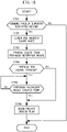
- FIG. 8C is a flow chart explaining details of the processing for preparation of a second driving plan.
- the electronic control unit 20 of the vehicle 2 sets the current amount of battery electric power Wn as the amount of available battery electric power WA.
- the electronic control unit 20 of the vehicle 2 calculates the EV suitabilities of the driving sections based on the driving loads of the driving sections.
- the electronic control unit 20 of the vehicle 2 sets the driving section with the highest EV suitability among the driving sections for which the driving modes have not been set as the "driving mode setting section".
- step S144 the electronic control unit 20 of the vehicle 2 judges if the driving mode setting section can be set as an EV section.
- the electronic control unit 20 first calculates a second estimated amount of electric power W2[kWh] of the estimated value of the amount of electric power consumed when driving through the driving mode setting section in the EV mode based on the driving load of the driving mode setting section.
- the electronic control unit 20 calculates the estimated value W4[kWh] of the amount of electric power consumed if driving through the driving mode setting section and all driving sections already set as EV sections, if there are any such driving sections, in the EV mode (below, referred to as the "fourth estimated amount of electric power").
- step S142 when proceeding from step S142 through step S143 and first proceeding to the processing of the present step, there are still no driving sections set as EV sections, so the fourth estimated amount of electric power W4 becomes the second estimated amount of electric power W2 calculated at this step.
- the fourth estimated amount of electric power W4 becomes the value of the previous value of the fourth estimated amount of electric power W4 plus the second estimated amount of electric power W2 newly calculated after returning to the processing of the present step.
- the electronic control unit 20 judges if the amount of available battery electric power WA is greater than or equal to the fourth estimated amount of electric power W4. That is, the electronic control unit 20 judges if the amount of available battery electric power WA is greater than or equal to the amount of electric power enabling driving through the driving mode setting section and all driving sections already set as EV sections if any in the EV mode. Further, if the amount of available battery electric power WA is greater than or equal to the fourth estimated amount of electric power W4, the electronic control unit 20 judges that the driving mode setting section can be set as an EV section and proceeds to the processing of step S145. On the other hand, if the amount of available battery electric power WA is less than the fourth estimated amount of electric power W4, the electronic control unit 20 judges that the driving mode setting section cannot be set as an EV section and proceeds to the processing of step S146.
- the electronic control unit 20 of the vehicle 2 sets the driving mode setting section as an EV section.
- the electronic control unit 20 of the vehicle 2 sets the driving mode setting section as an HV section.
- step S147 the electronic control unit 20 of the vehicle 2 judges if there is any driving section for which the driving mode has not been set. If there is a driving section for which the driving mode has not been set, the electronic control unit 20 returns again to step S143 where the driving mode is set for the driving section for which the driving mode has not yet been set. On the other hand, if there is no driving section for which the driving mode has not yet been set, the electronic control unit 20 ends the preparation of the second driving plan.
- an electronic control unit 20 for controlling a vehicle 2 equipped with an internal combustion engine 211, a second rotating electric machine 214 (rotating electric machine), and a battery 215 is provided with a driving plan preparation part for preparing a driving plan dividing a scheduled driving route up to a destination of the vehicle 2 into a plurality of driving sections and setting which driving mode the driving sections should be driven in between an EV mode stopping the operation of the internal combustion engine 211 and driving by the drive power of the second rotating electric machine 214 and an HV mode running by drive power of the internal combustion engine 211 and the drive power of the second rotating electric machine 214 and a drive power control part for controlling the internal combustion engine 211 and the second rotating electric machine 214 based on the driving plan.
- the driving plan preparation part is configured so that, when a driving section is present inside a restricted region, it extracts as a restricted driving section from among driving sections present inside the restricted region a driving section through which it is projected the vehicle will be driven in a restricted time period in which operation of internal combustion engines 211 is restricted and prepares a driving plan able to drive through the restricted driving section in the EV mode.
- the driving plan preparation part is more specifically configured to set the driving mode of a restricted driving section as an EV mode, calculate the amount of electric power able to be used in the remaining driving sections other than the restricted driving section in the amount of electric power of the battery 215 as the amount of available battery electric power WA, and determine the driving modes of the remaining driving sections other than the restricted driving section based on the amount of available battery electric power WA. Further, the amount of available battery electric power WA is made the remaining amount of electric power obtained by subtracting from the current amount of battery electric power Wn the first estimated amount of electric power W1 of the estimated value of the amount of electric power consumed if driving through the restricted driving section in the EV mode.
- the driving plan preparation part is configured so as to set a driving section with a driving load greater than or equal to a predetermined load among the driving sections for which the driving mode is set to the HV mode as a charging section for utilizing the drive power of the internal combustion engine 211 to charge the battery 215.
- the load of the internal combustion engine 211 increases by exactly the amount for generating the electric power for charging the battery 215 and as a result the noise of the internal combustion engine 211 increases. Therefore, for example, if charging the battery 215 when the internal combustion engine 211 is being operated in a relatively low load side engine operating region or otherwise it is believed the noise is small, the noise of the internal combustion engine 211 ends up becoming noticeable and the vehicle occupants are liable to feel uncomfortable with the noise of the internal combustion engine 211.
- the internal combustion engine 211 by charging the battery 215 in a driving section where the driving load becomes greater than or equal to a predetermined load, it is possible to charge the battery 215 in a driving section where it is projected the internal combustion engine 211 will more often be operated in a relatively high load side engine operating region, that is, a driving section where it is believed the noise would be great. For this reason, it is possible to keep the noise of the internal combustion engine 211 from ending up becoming noticeable at the time of charging the battery 215 and keep the vehicle occupants from feeling uncomfortable about the noise of the internal combustion engine 211.
- the present embodiment differs from the first embodiment on the point of preparing a driving plan of a current trip considering the next trip starting from that destination to a new next destination if the destination of the current trip is present inside a restricted region. Below, that point of difference will be focused on in the explanation.
- the vehicle starts from the destination of the current trip present inside the restricted region toward the next destination. Therefore, if the next trip is started toward the next destination in the restricted time period, it becomes necessary to run in the EV mode from inside the restricted region until escaping from the restricted region. For this reason, if the amount of battery electric power at the time of start of the next trip is small, it is liable to become impossible to escape from inside the restricted region.
- the driving plan of the current trip is prepared so as to enable an amount of battery electric power necessary for escaping from inside the restricted region to outside the restricted region in the next trip to be left.
- FIG. 9A is a flow chart explaining details of the processing for preparation of a first driving plan according to the present embodiment.
- the contents of the processing of steps S121 to S123 and S125 to S132 are similar to the first embodiment, so explanations will be omitted here.
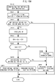
- FIG. 9B is a flow chart explaining details of the processing for setting the amount of available battery electric power WA according to the present embodiment performed during this first driving plan processing.
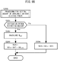
- the electronic control unit 20 of the vehicle 2 calculates the distances from the destination to road positions at the boundary GF of the restricted region (in the example shown in FIG. 2 , Kd, Ke, Kf, Kg) and calculates the estimated value W ESC [kWh] of the minimum necessary amount of electric power for escaping from the inside of the restricted region based on the shortest distance among them (below, referred to as the "estimated amount of escape electric power").
- the electronic control unit 20 of the vehicle 2 sets the amount of electric power obtained by subtracting from the current amount of battery electric power Wn the first estimated amount of electric power W1 and the estimated amount of escape electric power W ESC as the amount of available battery electric power WA. Due to this, it is possible to prepare a driving plan so that an amount of battery electric power of exactly the amount of the estimated amount of escape electric power W ESC remains at the end of the current trip.
- the electronic control unit 20 of the vehicle 2 sets the amount of electric power obtained by subtracting from the current amount of battery electric power Wn the first estimated amount of electric power W1 as the amount of available battery electric power WA. Due to this, when the destination is not present inside a restricted region, it is possible to use up the amount of battery electric power without waste by driving according to the driving plan, so it is possible to keep down the amount of fuel consumption.
- FIG. 10A is a flow chart explaining details of the processing for preparation of a second driving plan according to the present embodiment.
- the contents of the processing of steps S142 to S147 are similar to the first embodiment, so the explanation will be omitted here.
- step S210 the electronic control unit 20 of the vehicle 2 performs processing for setting the amount of available battery electric power WA. Details of the processing for setting the amount of available battery electric power WA according to the present embodiment performed in this second driving plan processing will be explained with reference to FIG. 10B .
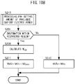
- FIG. 10B is a flow chart explaining details of the processing for setting the amount of available battery electric power WA according to the present embodiment performed during the second driving plan.
- the contents of the processing of steps S201, S202 of FIG. 10B are similar to the contents of the processing explained with reference to FIG. 9B , so explanations will be omitted here.
- the electronic control unit 20 of the vehicle 2 sets the amount of electric power obtained by subtracting from the current amount of battery electric power Wn the estimated amount of escape electric power W ESC as the amount of available battery electric power WA.
- the electronic control unit 20 of the vehicle 2 sets the current amount of battery electric power Wn as the amount of available battery electric power WA.
- the electronic control unit 20 is provided with a driving plan preparation part for preparing a driving plan dividing a scheduled driving route up to a destination of the vehicle 2 into a plurality of driving sections and setting which driving mode the driving sections should be driven in between an EV mode stopping the operation of the internal combustion engine 211 and driving by the drive power of the second rotating electric machine 214 and an HV mode running by drive power of the internal combustion engine 211 and the drive power of the second rotating electric machine 214.
- the driving plan preparation part is configured so that when calculating the amount of electric power able to be used in the remaining driving sections other than the restricted driving section in the current amount of battery electric power Wn as the amount of available battery electric power WA, it calculates the first estimated amount of electric power W1 of the estimated value of the amount of electric power consumed if driving through the restricted driving section in the EV mode and the estimated amount of escape electric power W ESC of the estimated value of the amount of electric power required for escaping from the destination to the outside of the restricted region.
- the driving plan preparation part is configured to set the remaining amount of electric power obtained by subtracting from the current amount of battery electric power Wn the first estimated amount of electric power W1 and the estimated amount of escape electric power W ESC as the amount of available battery electric power WA and determining the driving modes of the remaining driving sections other than the restricted driving section based on the amount of available battery electric power WA.
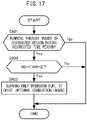
- the driving plan of the current trip was prepared so that if the destination of the current trip of the vehicle 2 was present inside a restricted region, it was possible to leave an estimated amount of escape electric power W ESC of an estimated value of the amount of battery electric power required for escaping from inside the restricted region to outside the restricted region in the next trip.
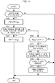
- step S301 the electronic control unit 20 of the vehicle 2 judges if it is scheduled to charge the battery 215 at the destination of the current trip. If it is scheduled to charge the battery 215 at the destination of the current trip, the electronic control unit 20 proceeds to the processing of step S302. On the other hand, if it is not scheduled to charge the battery 215 at the destination of the current trip, the electronic control unit 20 proceeds to the processing of step S203.
- the occupant is made to confirm whether there is a schedule for charging at the destination before input. Further, if there is a schedule for charging at the destination, to obtain a grasp of to what extent the battery 215 can be charged at the destination of the current trip, the occupant is further made to input the scheduled charging time at the destination.
- the method of judging if there is a schedule for charging the battery 215 at the destination of the current trip is not limited to such a method. For example, it is made possible to judge this according to the type of the destination input through the HMI device 25 (for example, the home or a location with a charging station etc.) or the past results of charging at the destination etc.
- the electronic control unit 20 of the vehicle 2 calculates the estimated value W CHG [kWh] of the amount of electric power charged at the battery 215 at the destination after reaching the destination of the current trip based on the scheduled charging time (below, referred to as the "estimated amount of charged electric power").
- the estimated amount of charged electric power W CHG becomes a larger value the longer the scheduled charging time.
- step S303 the electronic control unit 20 of the vehicle 2 judges if the estimated amount of charged electric power W CHG is greater than or equal to the estimated amount of escape electric power W ESC .
- step S304 the remaining amount of electric power obtained by subtracting from the current amount of battery electric power Wn the first estimated amount of electric power W1 is set as the amount of available battery electric power WA.
- the electronic control unit 20 proceeds to the processing of step S305.
- the electronic control unit 20 of the vehicle 2 sets the remaining amount of electric power, obtained by subtracting from the current amount of battery electric power Wn the first estimated amount of electric power W1 and amount of short electric power W SHTG , as the amount of available battery electric power WA.
- FIG. 12 is a flow chart explaining details of processing for setting the amount of available battery electric power WA according to the present embodiment performed in the second driving plan processing.
- the contents of the processing of steps S201 and S202, the contents of the processing of S211 and S212, and the contents of the processing of S301 to S303 are as explained above referring to respectively FIG. 9B , FIG. 10B , and FIG. 11 , so explanations will be omitted here.
- step S311 since the estimated amount of charged electric power W CHG is greater than or equal to estimated amount of escape electric power W ESC , there is no need to leave the estimated amount of escape electric power W ESC for the next trip, and there is no problem even if ending up using the amount of battery electric power up at the current trip, the electronic control unit 20 of the vehicle 2 sets the current amount of battery electric power Wn as the amount of available battery electric power WA.
- the electronic control unit 20 according to the present embodiment explained above also, in the same way as the first embodiment, is provided with a driving plan preparation part for preparing a driving plan dividing a scheduled driving route up to a destination of the vehicle 2 into a plurality of driving sections and setting which driving mode the driving sections should be driven in between an EV mode stopping the operation of the internal combustion engine 211 and driving by the drive power of the second rotating electric machine 214 and an HV mode running by drive power of the internal combustion engine 211 and the drive power of the second rotating electric machine 214.
- the driving plan preparation part is configured so that if the destination is present inside a restricted region, when scheduled to charge the battery 215 at the destination, it prepares a driving plan where the amount of electric power of the battery 215 at the time of starting the next trip starting from the destination does not fall below the amount of electric power required for escaping from the destination to outside the restricted region.
- the driving plan preparation part calculates the amount of electric power able to be used in the remaining driving sections other than the restricted driving section in the current amount of battery electric power Wn as the amount of available battery electric power WA during which it calculates the first estimated amount of electric power W1 of the estimated value of the amount of electric power consumed when running through the restricted driving section in the EV mode, the estimated amount of escape electric power W ESC of the estimated value of the amount of electric power required for escaping from the destination to the outside of the restricted region, and the estimated amount of charged electric power W CHG of the estimated value of the amount of electric power charged at the destination.
- the present embodiment differs from the above embodiments on the point of changing the scheduled driving route if running while switching the driving mode in accordance with a driving plan and the vehicle is liable to have to enter a restricted region in a restricted time period in a state with the amount of battery electric power smaller than a predetermined value. Below, this point of difference will be focused on in the explanation.
- step S401 the electronic control unit 20 of the vehicle 2 judges if a driving plan has been newly prepared. If a driving plan has been newly prepared, the electronic control unit 20 proceeds to the processing of step S402. On the other hand, if a driving plan has not been newly prepared, the electronic control unit 20 ends the current processing.
- the electronic control unit 20 of the vehicle 2 calculates the estimated amount of entry battery electric power W BAT projected when running while switching driving modes in accordance with the newly prepared driving plan.
- the method of calculating the estimated amount of entry battery electric power W BAT is not particularly limited, but, for example, it can be calculated by subtracting from the current amount of battery electric power Wn the estimated value of the amount of electric power consumed when running through all of the EV sections present before the restricted region in the EV mode.
- the electronic control unit 20 of the vehicle 2 judges if the estimated amount of entry battery electric power W BAT is less than the first threshold value Wthl. If the estimated amount of entry battery electric power W BAT is less than the first threshold value Wthl, the electronic control unit 20 proceeds to the processing of step S404. On the other hand, if the estimated amount of entry battery electric power W BAT is greater than or equal to the first threshold value Wthl, the electronic control unit 20 judges that there is no need to change the scheduled driving route and ends the current processing.
- the electronic control unit 20 sets an amount of electric power of an extent enabling passage through the restricted region (for example, an amount of electric power of an extent enabling driving from one road position to another road position on the boundary GF of the restricted region) as the first threshold value Wthl.
- the server 1 if information relating to the amount of battery electric power when one or more other vehicles enter the restricted region is collected at the server 1 as macro data, it is possible to set the first threshold value Wthl based on the distribution of data of the amount of entry battery electric power into the restricted region collected at the server 1. Specifically, it is possible to set the center value or average value or most frequent value etc. in the distribution of data of the amounts of battery electric power at the time of entry into the restricted region collected at the server 1 as the first threshold value Wthl.
- the first threshold value Wthl based on the weather around the restricted region. Specifically, if the weather around the restricted region is cloudy or rain, the first threshold value Wthl may be set higher than if it is clear.
- the electronic control unit 20 of the vehicle 2 searches for an alternative driving route by which an increase in the estimated amount of entry battery electric power W BAT can be expected compared with the current scheduled driving route based on the current position information and the map information.
- the electronic control unit 20 for example, searches among the plurality of driving routes from the current position until entry into the restricted region for a driving route with many driving sections suitable for the HV mode and by which it is believed that the distance running in the EV mode would become shorter than the current scheduled driving route as an alternative driving route.
- it searches among the plurality of driving routes from the current position until entry into the restricted region for a driving route with many downhill slopes, a driving route with many driving sections with relatively high driving loads and suitable for running while charging the battery 215 using the drive power of the internal combustion engine 211, or another driving route by which it is believed the amount of regenerated electric power will become greater than the current driving route, as an alternative driving route.
- the electronic control unit 20 of the vehicle 2 proposes a change of route to the alternative driving route to the vehicle occupants through the HMI device 25.
- the electronic control unit 20 of the vehicle 2 judges if the change of route to the alternative driving route has been approved by a vehicle occupant.
- the electronic control unit 20 judges that the change of route to the alternative driving route has been approved by a vehicle occupant when a vehicle occupant indicates his or her intent of approval through the HMI device 25 before a predetermined time elapses from when change of route to the alternative driving route was proposed.
- the electronic control unit 20 proceeds to the processing of step S407.
- the electronic control unit 20 ends the current processing.
- the electronic control unit 20 of the vehicle 2 changes the scheduled driving route to the alternative driving route.
- the electronic control unit 20 is configured to calculate an estimated amount of entry battery electric power W BAT of an estimated value of the amount of electric power of the battery 215 when entering a restricted region projected when driving along a scheduled driving route in accordance with the driving plan and search for an alternative driving route taking the place of the scheduled driving route if the estimated amount of entry battery electric power W BAT is less than the predetermined first threshold value Wthl.
- the estimated amount of entry battery electric power W BAT is less than the first threshold value Wthl, it is possible to propose an alternative driving route to the vehicle occupants or, if the vehicle 2 is an automated driving vehicle able to autonomously run, automatically change the scheduled driving route to the alternative driving route. For this reason, for example, it is possible to keep from falling in a situation where the vehicle ends up entering a restricted region in a restricted time period in a state where the amount of electric power of the battery 215 is not sufficiently secured.
- the present embodiment differs from the fourth embodiment on the point of setting the estimated amount of entry battery electric power W BAT calculated based on the driving plan prepared at the time of start of the trip as the first threshold value Wthl. Below, this point of difference will be focused on in the explanation.
- FIG. 14 is a flow chart explaining control for searching for an alternative driving route according to the present embodiment.
- the contents of processing of steps S401 to S407 of FIG. 14 are similar to the fourth embodiment, so here the explanations will be omitted.
- step S501 the electronic control unit 20 of the vehicle 2 judges if the newly prepared driving plan is a driving plan first prepared in the current trip.
- step S502 the electronic control unit 20 proceeds to the processing of step S502 where it sets the estimated amount of entry battery electric power W BAT , calculated based on the driving plan first prepared in the current trip, as the first threshold value Wthl.
- the electronic control unit 20 proceeds to the processing of step S403 and on where it judges if the estimated amount of entry battery electric power W BAT , calculated based on the driving plan first prepared in the current trip, is less than the first threshold value Wthl set at step S502. Further, if the estimated amount of entry battery electric power W B A T is less than the first threshold value Wthl, it proposes a change of route to an alternative driving route to the vehicle occupants through the HMI device 25.
- the electronic control unit 20 according to the present embodiment explained above, in the same way as the fourth embodiment, is configured to search for an alternative driving route for taking the place of the scheduled driving route if the estimated amount of entry battery electric power W BAT is less than a predetermined first threshold value Wthl and set the estimated amount of entry battery electric power W BAT calculated when first preparing a driving plan in the current trip as the first threshold value Wthl. Even if configuring the electronic control unit 20 in this way, it is possible to obtain actions and effects corresponding to the fourth embodiment.
- the present embodiment differs from the above embodiments on the point of providing the vehicle occupants with position information of charging stations in accordance with the amount of battery electric power when actually entering a restricted region in a restricted time period. Below, this point of difference will be focused on in the explanation.
- FIG. 15 is a flow chart for explaining control for providing information according to the present embodiment.
- the electronic control unit 20 of the vehicle 2 repeatedly performs the present routine at predetermined processing cycles.
- the electronic control unit 20 of the vehicle 2 judges if the host vehicle has entered a restricted region in a restricted time period.
- the method of judgment of whether the host vehicle has entered a restricted region in a restricted time period is not particularly limited. For example, it is possible to judge this based on the current position information, map information, and restricted region information. If the host vehicle enters a restricted region in a restricted time period, the electronic control unit 20 proceeds to the processing of step S602. On the other hand, if the host vehicle does not enter a restricted region in a restricted time period, the electronic control unit 20 ends the current processing.
- step S602 the electronic control unit 20 of the vehicle 2 judges if the current amount of battery electric power Wn is less than the first threshold value Wthl. If the amount of battery electric power Wn is less than the first threshold value Wthl, the electronic control unit 20 proceeds to the processing of step S603. On the other hand, if the amount of battery electric power Wn is greater than or equal to the first threshold value Wthl, the electronic control unit 20 judges the minimum extent of the amount of battery electric power required for entry into the restricted region in a restricted time period has been secured and ends the current processing.
- step S603 the electronic control unit 20 of the vehicle 2 judges if the destination of the host vehicle is known. If the destination of the host vehicle is known, the electronic control unit 20 proceeds to the processing of step S604. On the other hand, if the destination of the host vehicle is not known, the electronic control unit 20 proceeds to the processing of step S607.
- step S604 the electronic control unit 20 of the vehicle 2 judges if the destination is present inside a restricted region. If the destination is present inside a restricted region, the electronic control unit 20 proceeds to the processing of step S605. On the other hand, if the destination is not present inside a restricted region, the electronic control unit 20 proceeds to the processing of step S606.
- the electronic control unit 20 of the vehicle 2 provides position information on nearby charging stations present on the scheduled driving route and position information on parking lots with chargers present near the destination through the HMI device 25 to the vehicle occupants.
- the electronic control unit 20 of the vehicle 2 provides position information on nearby charging stations present on the scheduled driving route through the HMI device 25 to the vehicle occupants.
- the electronic control unit 20 of the vehicle 2 provides position information on nearby charging stations through the HMI device 25 to the vehicle occupants.
- the position information on charging stations or the position information of parking lots with chargers was provided to the vehicle occupants, but, for example, when the vehicle 2 is an automated driving vehicle able to autonomously run, it is also possible to automatically switch the destination to the nearest charging station or parking lot with a charger and make the vehicle 2 head to the switched destination.
- the electronic control unit 20 is configured to search for possible charging locations at which the battery 215 can be charged and, when the destination is inside a restricted region, provide the occupants of the vehicle 2 with at least position information of possible charging locations near the destination or change the destination to a possible charging location near the destination.
- FIG. 16 is a flow chart for explaining control for escape from a temporary restricted region according to the present embodiment.
- the electronic control unit 20 of the vehicle communicates with the server 1 to acquire restricted region information and judges if the host vehicle is running inside a temporary restricted region based on the current position information. If if the host vehicle is running inside a temporary restricted region, the electronic control unit 20 proceeds to the processing of step S702. On the other hand, if the host vehicle is not running inside a temporary restricted region, the electronic control unit 20 ends the current processing.
- the electronic control unit 20 of the vehicle 2 searches for the shortest escape route by which it is possible to escape from the current position to outside the temporary restricted region based on the current position information and map information.
- the electronic control unit 20 of the vehicle 2 proposes escape from the temporary restricted region to the vehicle occupants through the HMI device 25.
- the electronic control unit 20 of the vehicle 2 judges if escape from the temporary restricted region has been approved by a vehicle occupant.
- the electronic control unit 20 judges that escape from the temporary restricted region has been approved by a vehicle occupant when a vehicle occupant indicates his or her intent of approval through the HMI device 25 before a predetermined time has elapsed after proposing escape from the temporary restricted region.
- the electronic control unit 20 proceeds to the processing of step S705.
- step S706 the electronic control unit 20 proceeds to the processing of step S706 where it prepares a driving plan optimizing the driving route from the current position to the destination after considering the temporary restricted region.
- step S705 the electronic control unit 20 of the vehicle 2 judges if the host vehicle has escaped from the temporary restricted region based on the current position information. If the host vehicle has escaped from the temporary restricted region, the electronic control unit 20 proceeds to the processing of step S706. On the other hand, if the host vehicle has not escaped from the temporary restricted region, the electronic control unit 20 waits for a predetermined interval and again performs the processing of step S705.
- the electronic control unit 20 of the vehicle 2 prepares a driving plan optimizing the driving route from the current position (point of escape) to the destination considering the temporary restricted region.
- the shortest escape route was searched for and escape from the temporary restricted region was proposed to the vehicle occupants, but for example if the vehicle 2 is an automated driving vehicle able to autonomously run, it is also possible to make the vehicle automatically run over the shortest escape route to make it escape from the temporary restricted region.
- the electronic control unit 20 is configured so as to search for the shortest escape route enabling escape from the temporary restricted region when, while driving through a point where operation of internal combustion engines 211 is not restricted, that point becomes inside a temporary restricted region where operation of internal combustion engines 211 is restricted temporarily or abruptly.
- the present embodiment differs from the above embodiments in the configuration of the internal combustion engine 211. Below, this point of difference will be focused on in the explanation.
- the internal combustion engine 211 is configured to be able to burn hydrogen fuel at part of the cylinders and to burn gasoline fuel (fossil fuel) at the remaining cylinders. Due to this, when burning only hydrogen fuel to operate the internal combustion engine 211, the amount of exhaust of carbon dioxide from the internal combustion engine 211 becomes zero. Therefore, if the restricted region is set with the object of prevention of global warming, even inside a restricted region in a restricted time period, burning only hydrogen fuel to operate the internal combustion engine 211 is allowed.
- the amount of battery electric power will not necessarily be managed as planned.
- the amount of battery electric power may greatly fall contrary to expectations.
- the amount of battery electric power may become insufficient and the electric power may run out thereby rendering driving impossible.
- a restricted region being set for the purpose of prevention of global warming, it is made so that if driving through the inside of a restricted region in a restricted time period in the EV mode in accordance with a driving plan, when the amount of battery electric power Wn has become less than a predetermined second threshold value Wth2, only hydrogen fuel is burned to operate the internal combustion engine 211. Due to this, it is possible to run the vehicle 2 by the drive power of the internal combustion engine 211 and, further, possible to generate electric power by regenerative operation of the first rotating electric machine 213.
- the second threshold value Wth2 is made an amount of electric power of an extent, for example, enabling driving from the center part of the restricted region to the boundary.
- FIG. 17 is a flow chart explaining control for operating the internal combustion engine 211 according to the present embodiment.
- step S801 the electronic control unit 20 of the vehicle 2 judges if the host vehicle is running inside a restricted region in a restricted time period. If the host vehicle is running inside a restricted region during a restricted time period, the electronic control unit 20 proceeds to the processing of step S802. On the other hand, if the host vehicle is not running inside a restricted region during a restricted time period, the electronic control unit 20 ends the current processing.
- step S802 the electronic control unit 20 of the vehicle 2 judges if the current amount of battery electric power Wn is less than the second threshold value Wth2. If the current amount of battery electric power Wn is less than the second threshold value Wth2, the electronic control unit 20 proceeds to the processing of step S803. On the other hand, if the current amount of battery electric power Wn is greater than or equal to the second threshold value Wth2, the electronic control unit 20 ends the current processing.
- step S803 the electronic control unit 20 of the vehicle 2 burns only hydrogen fuel to operate the internal combustion engine 211.
- the internal combustion engine 211 is configured to enable hydrogen fuel to be burned at part of the cylinders and gasoline fuel (fossil fuel) to be burned at the remaining cylinders.
- the electronic control unit 20 is configured so that if driving through the inside of a restricted region in a restricted time period in the EV mode, when the amount of battery electric power Wn becomes less than the second threshold value Wth2, only hydrogen fuel is burned to operate the internal combustion engine 211 to make the vehicle 2 run by the drive power of the internal combustion engine 211 or the electric power generated utilizing the drive power of the internal combustion engine 211 is charged to the battery 215.
- the present embodiment differs from the above embodiments on the point that the vehicle 2 is not a hybrid vehicle provided with an internal combustion engine and a motor as sources of drive power, but a normal vehicle provided with only an internal combustion engine as a source of drive power. Below, this point of difference will be focused on in the explanation.
- FIG. 18 is a schematic view of the configuration of the vehicle 2 according to the present embodiment.
- the vehicle 2 is a normal vehicle provided with only an internal combustion engine 211 as the source of drive power and is configured to be able to transmit the drive power of the internal combustion engine 211 to the driving wheels.
- the internal combustion engine 211 is configured to be able to burn hydrogen fuel in part of the cylinders and burn gasoline fuel (fossil fuel) in the remaining cylinders.
- the vehicle 2 is provided with a remaining fuel amount sensor 28d detecting the remaining amount of fuel.
- the electronic control unit 20 is configured to be able to switch the driving mode of the vehicle 2 to either of the hydrogen mode or the gasoline mode.
- the hydrogen mode is a mode burning only hydrogen fuel to drive the internal combustion engine 211.
- the gasoline mode is a mode burning at least gasoline fuel to drive the internal combustion engine 211.
- the electronic control unit 20 prepares a driving plan regarding which driving sections on the scheduled driving route to run through in a hydrogen mode and which driving sections to run through in a gasoline mode while considering restricted regions and make the vehicle 2 run while switching the driving mode in accordance with the driving plan.
- FIG. 19A is a flow chart explaining details of the processing for preparation of a first driving plan according to the present embodiment.
- the electronic control unit 20 of the vehicle 2 sets the restricted driving sections as hydrogen sections for running in the hydrogen mode.
- the electronic control unit 20 of the vehicle 2 calculates the estimated value Q1[L] of the hydrogen fuel consumed when driving through all of the restricted driving sections in the hydrogen mode based on the driving loads of the restricted driving sections (below, referred to as the "estimated amount of fuel consumption").
- step S905 the electronic control unit 20 of the vehicle 2 judges if the amount of available hydrogen fuel QA is greater than zero. If the amount of available hydrogen fuel QA is greater than zero, the electronic control unit 20 proceeds to the processing of step S906. On the other hand, if the amount of available hydrogen fuel QA is less than or equal to zero, the electronic control unit 20 proceeds to the processing of step S908.
- step S906 the electronic control unit 20 of the vehicle 2 judges if the driving mode of the first driving section in which the vehicle first runs on the scheduled driving route (that is, the driving section including the starting point) has not yet been set. If the driving mode of the first driving section has not yet been set, the electronic control unit 20 proceeds to the processing of step S907. On the other hand, if the driving mode of the first driving section has already been set, the electronic control unit 20 proceeds to the processing of step S909.
- the electronic control unit 20 of the vehicle 2 sets the first driving section as a hydrogen section and sets all of the remaining driving sections as gasoline sections.
- the first driving section is set as a hydrogen section for the following reason. That is, if driving the internal combustion engine 211 by burning gasoline fuel, which is liquid fuel at the time of a cold state before the internal combustion engine 211 has finished warming up, the exhaust emission tends to deteriorate due to the effect of the gasoline fuel adhering to the cylinder wall surfaces. Therefore, by setting the first driving section as a hydrogen section, at the time of a cold state of the internal combustion engine 211, it is possible to operate the internal combustion engine 211 by burning the gaseous hydrogen fuel and as a result it is possible to keep the exhaust emission from deteriorating.
- step S908 hydrogen fuel becomes insufficient for driving through the restricted driving section in the hydrogen mode, so the electronic control unit 20 of the vehicle 2 proposes the resupply of hydrogen fuel to the vehicle occupants through the HMI device 25.
- FIG. 19B is a flow chart explaining details of the processing for preparation of a second driving plan according to the present embodiment. Note that in FIG. 19B , the contents of the processing of steps S905 to S909 are similar to the contents of the above-mentioned processing explained above with reference to FIG. 19A , so here the processing will be omitted.
- the electronic control unit 20 of the vehicle 2 calculates the current amount of hydrogen fuel Qn detected by the remaining fuel amount sensor 28d as the amount of available hydrogen fuel QA.
- a driving plan enabling running in the restricted driving section and the first driving section in the hydrogen mode was prepared, but a driving plan setting other driving sections to the hydrogen mode in addition to these driving sections in accordance with the remaining amount of hydrogen may also be prepared.
- the electronic control unit 20 for controlling a vehicle 2 equipped with an internal combustion engine 211 configured to be able to burn hydrogen fuel in part of the cylinders and able to burn a fossil fuel in the remaining cylinders is provided with a driving plan preparation part for preparing a driving plan dividing a scheduled driving route up to a destination of the vehicle 2 into a plurality of driving sections and setting which driving mode the driving sections should be driven in between a hydrogen mode (first mode) driving by burning only hydrogen fuel or a gasoline mode (second mode) driving by burning at least fossil fuel and a drive power control part for controlling the internal combustion engine 211 based on the driving plan.
- a driving plan preparation part for preparing a driving plan dividing a scheduled driving route up to a destination of the vehicle 2 into a plurality of driving sections and setting which driving mode the driving sections should be driven in between a hydrogen mode (first mode) driving by burning only hydrogen fuel or a gasoline mode (second mode) driving by burning at least fossil fuel
- a drive power control part for controlling the internal combustion engine 211
- the driving plan preparation part is configured so that, when driving sections are present inside a restricted region, it extracts as a restricted driving section from among driving sections present inside the restricted region a driving section through which it is projected that the vehicle 2 will be driven in a restricted time period in which burning fossil fuel to operate the internal combustion engine 211 is restricted and prepares a driving plan able to drive through the restricted driving section in the hydrogen mode.
- the electronic control unit 20 is configured to provide occupants of a vehicle 2 the position information of locations able to resupply hydrogen fuel when the remaining amount of hydrogen fuel is less than an estimated value of the amount of hydrogen fuel consumed when driving through a restricted driving section in the hydrogen mode (first mode), so it is possible to keep from falling in a situation where the remaining amount of hydrogen becomes insufficient while driving through a restricted driving section.
- the restricted region information was acquired from the server 1, but the invention is not limited to this.
- the restricted region information may be stored in advance in the vehicle storage part 202 of the electronic control unit 20 or another vehicle-mounted storage device. If a road traffic information communication system center or other outside communication center periodically sends restricted region information, it may also be acquired by receiving the restricted region information sent from the outside communication center.
Landscapes
- Engineering & Computer Science (AREA)
- Transportation (AREA)
- Mechanical Engineering (AREA)
- Chemical & Material Sciences (AREA)
- Combustion & Propulsion (AREA)
- Automation & Control Theory (AREA)
- Remote Sensing (AREA)
- Radar, Positioning & Navigation (AREA)
- Power Engineering (AREA)
- Physics & Mathematics (AREA)
- General Physics & Mathematics (AREA)
- Sustainable Energy (AREA)
- Sustainable Development (AREA)
- Human Computer Interaction (AREA)
- Life Sciences & Earth Sciences (AREA)
- Electric Propulsion And Braking For Vehicles (AREA)
- Hybrid Electric Vehicles (AREA)
- Navigation (AREA)
Applications Claiming Priority (1)
| Application Number | Priority Date | Filing Date | Title |
|---|---|---|---|
| JP2021008943A JP7363826B2 (ja) | 2021-01-22 | 2021-01-22 | 車両制御装置及び車両制御方法 |
Publications (2)
| Publication Number | Publication Date |
|---|---|
| EP4043257A2 true EP4043257A2 (de) | 2022-08-17 |
| EP4043257A3 EP4043257A3 (de) | 2022-10-12 |
Family
ID=80218701
Family Applications (1)
| Application Number | Title | Priority Date | Filing Date |
|---|---|---|---|
| EP22152721.1A Pending EP4043257A3 (de) | 2021-01-22 | 2022-01-21 | Fahrzeugsteuerungsvorrichtung und fahrzeugsteuerungsverfahren |
Country Status (4)
| Country | Link |
|---|---|
| US (1) | US11834032B2 (de) |
| EP (1) | EP4043257A3 (de) |
| JP (1) | JP7363826B2 (de) |
| CN (1) | CN114802196A (de) |
Families Citing this family (4)
| Publication number | Priority date | Publication date | Assignee | Title |
|---|---|---|---|---|
| JP2024065571A (ja) * | 2022-10-31 | 2024-05-15 | トヨタ自動車株式会社 | ハイブリッド電気車両 |
| JP7715135B2 (ja) * | 2022-11-16 | 2025-07-30 | トヨタ自動車株式会社 | ハイブリッド電気車両 |
| JP2025070470A (ja) * | 2023-10-20 | 2025-05-02 | トヨタ自動車株式会社 | ハイブリッド車 |
| CN118701023A (zh) * | 2024-08-27 | 2024-09-27 | 张家港长城汽车研发有限公司 | 一种车辆的控制方法、车辆及存储介质 |
Citations (1)
| Publication number | Priority date | Publication date | Assignee | Title |
|---|---|---|---|---|
| JP2019151316A (ja) | 2018-03-02 | 2019-09-12 | トヨタ自動車株式会社 | ハイブリッド車両の制御装置 |
Family Cites Families (50)
| Publication number | Priority date | Publication date | Assignee | Title |
|---|---|---|---|---|
| JP3264123B2 (ja) * | 1995-03-06 | 2002-03-11 | 三菱自動車工業株式会社 | ハイブリッド電気自動車用ナビゲーションシステム |
| JP3211699B2 (ja) * | 1996-09-17 | 2001-09-25 | トヨタ自動車株式会社 | 動力出力装置 |
| US6439192B1 (en) * | 2000-10-24 | 2002-08-27 | Westport Research Inc. | Gaseous and liquid fuel injection valve with concentric needles |
| US9193268B2 (en) * | 2001-03-27 | 2015-11-24 | General Electric Company | Hybrid energy power management system and method |
| JP3632634B2 (ja) * | 2001-07-18 | 2005-03-23 | 日産自動車株式会社 | ハイブリッド車両の制御装置 |
| US6814170B2 (en) * | 2001-07-18 | 2004-11-09 | Nissan Motor Co., Ltd. | Hybrid vehicle |
| JP4331905B2 (ja) * | 2001-09-28 | 2009-09-16 | パイオニア株式会社 | ハイブリッドカー、及びハイブリッドカーの制御方法 |
| JP4831925B2 (ja) * | 2002-09-26 | 2011-12-07 | トヨタ自動車株式会社 | 燃料電池システムの燃料残量に関する警告 |
| JP2004156622A (ja) * | 2003-12-05 | 2004-06-03 | Denso Corp | エンジン駆動規制支援装置 |
| WO2005097573A2 (en) * | 2004-03-30 | 2005-10-20 | Railpower Technologies Corp. | Emission management for a hybrid locomotive |
| JP4506613B2 (ja) * | 2004-11-12 | 2010-07-21 | マツダ株式会社 | パワートレインの制御装置 |
| US7222004B2 (en) * | 2005-02-02 | 2007-05-22 | Deere & Company | Vehicular navigation with location-based noise reduction |
| JP2006311769A (ja) * | 2005-05-02 | 2006-11-09 | Denso Corp | ハイブリットカーの制御装置 |
| US7665559B2 (en) * | 2005-06-10 | 2010-02-23 | De La Torre-Bueno Jose | Inputs for optimizing performance in hybrid vehicles |
| DE102005037553A1 (de) * | 2005-08-09 | 2007-02-15 | Robert Bosch Gmbh | Verfahren zur Ansteuerung eines Hybridfahrzeugs und Hybridfahrzeug |
| JP4281725B2 (ja) * | 2005-09-01 | 2009-06-17 | トヨタ自動車株式会社 | ハイブリッド自動車 |
| EP2070788B1 (de) * | 2006-09-28 | 2013-01-09 | Toyota Jidosha Kabushiki Kaisha | Fahrzeugsteuervorrichtung |
| JP4737028B2 (ja) * | 2006-10-18 | 2011-07-27 | マツダ株式会社 | デュアルフューエルエンジンの制御装置 |
| KR100867822B1 (ko) * | 2006-12-11 | 2008-11-10 | 현대자동차주식회사 | 하이브리드 전기 차량의 배터리 온도 및 습도 조절 장치 |
| DE102007026320B4 (de) * | 2007-06-06 | 2009-07-09 | Siemens Enterprise Communications Gmbh & Co. Kg | Verfahren für den Betrieb eines Navigationssystems und Navigationssystem für ein Kraftfahrzeug |
| JP4924478B2 (ja) * | 2008-02-29 | 2012-04-25 | アイシン・エィ・ダブリュ株式会社 | 運転支援装置、方法およびプログラム |
| JP4450087B2 (ja) * | 2008-03-31 | 2010-04-14 | トヨタ自動車株式会社 | ハイブリッド車両およびその制御方法 |
| JP4927016B2 (ja) * | 2008-03-31 | 2012-05-09 | トヨタ自動車株式会社 | ナビゲーションシステムおよびそれを備えたハイブリッド車両 |
| US8180509B2 (en) * | 2009-03-12 | 2012-05-15 | Ford Global Technologies, Llc | Tail pipe emissions mode control for hybrid electric vehicles |
| DE102010039653A1 (de) | 2010-08-23 | 2012-02-23 | Bayerische Motoren Werke Aktiengesellschaft | Bestimmen des Aktivierungspunktes eines Range-Extenders in einem Elektrofahrzeug |
| US20120290149A1 (en) * | 2011-05-09 | 2012-11-15 | Ford Global Technologies, Llc | Methods and Apparatus for Selective Power Enablement with Predictive Capability |
| EP2578997B1 (de) * | 2011-10-07 | 2020-01-08 | Hitachi, Ltd. | System zur Unterstützung eines Benutzers eines elektrisch angetriebenen Fahrzeugs |
| US10344687B2 (en) * | 2011-12-16 | 2019-07-09 | Ge Global Sourcing Llc | Fuel selection method and related system for a mobile asset |
| US8676400B2 (en) * | 2012-02-03 | 2014-03-18 | Volkswagen Ag | Navigation system and method for an electric vehicle travelling from a starting point to a destination |
| US8972090B2 (en) * | 2012-04-04 | 2015-03-03 | Chrysler Group Llc | Predictive powertrain control using powertrain history and GPS data |
| CA2780864C (en) * | 2012-06-21 | 2013-09-24 | Westport Power Inc. | Fuel injection valve and method of actuating |
| EP2689982B1 (de) * | 2012-07-26 | 2017-11-08 | Fujitsu Limited | Verfahren zum Betrieb von Hybridfahrzeugen |
| JP5716779B2 (ja) * | 2013-03-22 | 2015-05-13 | トヨタ自動車株式会社 | ハイブリッド自動車 |
| JP2014213638A (ja) * | 2013-04-23 | 2014-11-17 | トヨタ自動車株式会社 | ハイブリッド車両の制御装置 |
| JP5929866B2 (ja) * | 2013-10-03 | 2016-06-08 | トヨタ自動車株式会社 | 移動支援装置、移動支援方法、及び運転支援システム |
| DE102013016569A1 (de) * | 2013-10-04 | 2015-04-09 | Man Truck & Bus Ag | Betriebsverfahren für einen Hybridantrieb, insbesondere zur Auswahl optimaler Betriebsmodi des Hybridantriebs entlang einer Fahrtroute |
| JP6136965B2 (ja) * | 2014-02-06 | 2017-05-31 | 株式会社デンソー | ハイブリッド車制御装置 |
| US9469289B2 (en) * | 2014-04-14 | 2016-10-18 | Ford Global Technologies, Llc | Energy reservation coordination for hybrid vehicle |
| JP2015214262A (ja) * | 2014-05-12 | 2015-12-03 | トヨタ自動車株式会社 | 車両 |
| DE102014014851B4 (de) * | 2014-10-07 | 2018-11-15 | Audi Ag | Verfahren zum Betrieb eines Navigationssystems eines Hybridkraftfahrzeugs und Hybridkraftfahrzeug |
| US9821790B2 (en) | 2015-12-17 | 2017-11-21 | Jaguar Land Rover Limited | System and method to facilitate satisfying low emission zone requirements |
| KR102444661B1 (ko) * | 2017-11-01 | 2022-09-19 | 현대자동차주식회사 | 하이브리드 자동차 및 그를 위한 주행 모드 제어 방법 |
| US10744892B2 (en) * | 2017-11-15 | 2020-08-18 | Ford Global Technologies, Llc | System and method for battery charging |
| US10401182B2 (en) * | 2017-12-13 | 2019-09-03 | Google Llc | Systems and methods for avoiding location-dependent driving restrictions |
| US11560136B2 (en) * | 2018-03-02 | 2023-01-24 | Toyota Jidosha Kabushiki Kaisha | Control device |
| JP6927133B2 (ja) * | 2018-04-19 | 2021-08-25 | トヨタ自動車株式会社 | ハイブリッド車両の制御装置 |
| JP7000999B2 (ja) * | 2018-06-08 | 2022-01-19 | トヨタ自動車株式会社 | 車両管理装置 |
| DE102018209453A1 (de) | 2018-06-13 | 2019-12-19 | Volkswagen Aktiengesellschaft | Verfahren zum Betrieb eines Fahrzeuges |
| KR102592831B1 (ko) * | 2018-12-07 | 2023-10-23 | 현대자동차주식회사 | 하이브리드 자동차 및 그를 위한 주행 제어 방법 |
| JP2020171077A (ja) * | 2019-04-01 | 2020-10-15 | 株式会社東芝 | エネルギー供給システム、情報処理装置、およびエネルギー供給装置 |
-
2021
- 2021-01-22 JP JP2021008943A patent/JP7363826B2/ja active Active
- 2021-12-06 US US17/457,759 patent/US11834032B2/en active Active
-
2022
- 2022-01-20 CN CN202210065586.4A patent/CN114802196A/zh active Pending
- 2022-01-21 EP EP22152721.1A patent/EP4043257A3/de active Pending
Patent Citations (1)
| Publication number | Priority date | Publication date | Assignee | Title |
|---|---|---|---|---|
| JP2019151316A (ja) | 2018-03-02 | 2019-09-12 | トヨタ自動車株式会社 | ハイブリッド車両の制御装置 |
Also Published As
| Publication number | Publication date |
|---|---|
| CN114802196A (zh) | 2022-07-29 |
| JP2022112913A (ja) | 2022-08-03 |
| JP7363826B2 (ja) | 2023-10-18 |
| US11834032B2 (en) | 2023-12-05 |
| US20220234567A1 (en) | 2022-07-28 |
| EP4043257A3 (de) | 2022-10-12 |
Similar Documents
| Publication | Publication Date | Title |
|---|---|---|
| EP4043257A2 (de) | Fahrzeugsteuerungsvorrichtung und fahrzeugsteuerungsverfahren | |
| JP7111469B2 (ja) | 車両制御システム、車両制御方法、およびプログラム | |
| CN101778732B (zh) | 搭载有蓄电装置的车辆及蓄电装置的温度控制方法 | |
| JP7176376B2 (ja) | 車両の制御装置 | |
| JP7571555B2 (ja) | ハイブリッド車両 | |
| JP7135735B2 (ja) | 通信制御装置、通信システム、通信制御装置が行う方法 | |
| JP7265423B2 (ja) | 経路計画装置、経路計画方法及び経路計画システム | |
| JP2010279108A (ja) | 電動車両のバッテリ充電制御装置 | |
| JP7371596B2 (ja) | ハイブリッド車両 | |
| KR20210079569A (ko) | 전기자동차의 주행 모드에 따른 주행 가능 거리 예측 장치 및 방법 | |
| US11648929B2 (en) | Hybrid vehicle | |
| EP3992044B1 (de) | Steuerungsvorrichtung für ein hybridfahrzeug und steuerungsverfahren für ein hybridfahrzeug | |
| US12246696B2 (en) | Hybrid vehicle controller that executes switching control for travel sections on a travel route according to the assigned control mode | |
| CN109878494A (zh) | 混合动力汽车及混合动力汽车用的控制装置 | |
| JP2021123290A (ja) | ハイブリッド車両 | |
| EP4008594B1 (de) | Steuerungsvorrichtung für ein hybridfahrzeug und steuerungsverfahren für ein hybridfahrzeug | |
| Giorgione et al. | Experimental analysis of eGLOSA and eGLODTA transit control strategies | |
| JP7593259B2 (ja) | 情報処理装置、及び、情報処理方法 | |
| JP2023072925A (ja) | 車両 |
Legal Events
| Date | Code | Title | Description |
|---|---|---|---|
| PUAI | Public reference made under article 153(3) epc to a published international application that has entered the european phase |
Free format text: ORIGINAL CODE: 0009012 |
|
| STAA | Information on the status of an ep patent application or granted ep patent |
Free format text: STATUS: REQUEST FOR EXAMINATION WAS MADE |
|
| 17P | Request for examination filed |
Effective date: 20220207 |
|
| AK | Designated contracting states |
Kind code of ref document: A2 Designated state(s): AL AT BE BG CH CY CZ DE DK EE ES FI FR GB GR HR HU IE IS IT LI LT LU LV MC MK MT NL NO PL PT RO RS SE SI SK SM TR |
|
| PUAL | Search report despatched |
Free format text: ORIGINAL CODE: 0009013 |
|
| AK | Designated contracting states |
Kind code of ref document: A3 Designated state(s): AL AT BE BG CH CY CZ DE DK EE ES FI FR GB GR HR HU IE IS IT LI LT LU LV MC MK MT NL NO PL PT RO RS SE SI SK SM TR |
|
| RIC1 | Information provided on ipc code assigned before grant |
Ipc: B60K 16/00 20200101ALI20220908BHEP Ipc: B60W 50/14 20200101ALI20220908BHEP Ipc: B60W 50/00 20060101ALI20220908BHEP Ipc: B60W 30/18 20120101ALI20220908BHEP Ipc: B60W 20/14 20160101ALI20220908BHEP Ipc: B60W 20/20 20160101ALI20220908BHEP Ipc: B60W 20/16 20160101ALI20220908BHEP Ipc: B60W 20/13 20160101ALI20220908BHEP Ipc: B60W 20/12 20160101ALI20220908BHEP Ipc: B60W 10/08 20060101ALI20220908BHEP Ipc: B60W 10/06 20060101ALI20220908BHEP Ipc: B60K 6/445 20071001AFI20220908BHEP |
|
| STAA | Information on the status of an ep patent application or granted ep patent |
Free format text: STATUS: EXAMINATION IS IN PROGRESS |
|
| 17Q | First examination report despatched |
Effective date: 20240925 |
|
| REG | Reference to a national code |
Ref country code: DE Ref legal event code: R079 Free format text: PREVIOUS MAIN CLASS: B60K0006445000 Ipc: B60K0035000000 |
|
| RIC1 | Information provided on ipc code assigned before grant |
Ipc: B60K 35/00 20060101AFI20251208BHEP Ipc: B60K 35/28 20240101ALI20251208BHEP Ipc: B60L 7/10 20060101ALI20251208BHEP Ipc: B60L 8/00 20060101ALI20251208BHEP Ipc: B60L 50/16 20190101ALI20251208BHEP Ipc: B60L 50/60 20190101ALI20251208BHEP Ipc: B60L 53/30 20190101ALI20251208BHEP Ipc: B60L 58/12 20190101ALI20251208BHEP Ipc: B60W 20/12 20160101ALI20251208BHEP Ipc: B60W 20/13 20160101ALI20251208BHEP Ipc: B60W 20/16 20160101ALI20251208BHEP Ipc: B60W 20/14 20160101ALI20251208BHEP Ipc: B60W 20/20 20160101ALI20251208BHEP Ipc: B60W 10/06 20060101ALI20251208BHEP Ipc: B60W 10/08 20060101ALI20251208BHEP Ipc: B60W 30/18 20120101ALI20251208BHEP Ipc: B60W 50/00 20060101ALI20251208BHEP Ipc: B60W 50/14 20200101ALI20251208BHEP Ipc: B60K 6/445 20071001ALI20251208BHEP |
|
| GRAP | Despatch of communication of intention to grant a patent |
Free format text: ORIGINAL CODE: EPIDOSNIGR1 |
|
| STAA | Information on the status of an ep patent application or granted ep patent |
Free format text: STATUS: GRANT OF PATENT IS INTENDED |
|
| INTG | Intention to grant announced |
Effective date: 20260119 |
|
| GRAS | Grant fee paid |
Free format text: ORIGINAL CODE: EPIDOSNIGR3 |
|
| GRAA | (expected) grant |
Free format text: ORIGINAL CODE: 0009210 |
|
| STAA | Information on the status of an ep patent application or granted ep patent |
Free format text: STATUS: THE PATENT HAS BEEN GRANTED |