EP4043263B1 - Procédé de commande ds fonctions de véhicule - Google Patents
Procédé de commande ds fonctions de véhicule Download PDFInfo
- Publication number
- EP4043263B1 EP4043263B1 EP22151074.6A EP22151074A EP4043263B1 EP 4043263 B1 EP4043263 B1 EP 4043263B1 EP 22151074 A EP22151074 A EP 22151074A EP 4043263 B1 EP4043263 B1 EP 4043263B1
- Authority
- EP
- European Patent Office
- Prior art keywords
- operating
- display
- display region
- area
- display area
- Prior art date
- Legal status (The legal status is an assumption and is not a legal conclusion. Google has not performed a legal analysis and makes no representation as to the accuracy of the status listed.)
- Active
Links
Images

Classifications
-
- G—PHYSICS
- G06—COMPUTING OR CALCULATING; COUNTING
- G06F—ELECTRIC DIGITAL DATA PROCESSING
- G06F3/00—Input arrangements for transferring data to be processed into a form capable of being handled by the computer; Output arrangements for transferring data from processing unit to output unit, e.g. interface arrangements
- G06F3/01—Input arrangements or combined input and output arrangements for interaction between user and computer
- G06F3/03—Arrangements for converting the position or the displacement of a member into a coded form
- G06F3/033—Pointing devices displaced or positioned by the user, e.g. mice, trackballs, pens or joysticks; Accessories therefor
- G06F3/0354—Pointing devices displaced or positioned by the user, e.g. mice, trackballs, pens or joysticks; Accessories therefor with detection of two-dimensional [2D] relative movements between the device, or an operating part thereof, and a plane or surface, e.g. 2D mice, trackballs, pens or pucks
- G06F3/03547—Touch pads, in which fingers can move on a surface
-
- B—PERFORMING OPERATIONS; TRANSPORTING
- B60—VEHICLES IN GENERAL
- B60K—ARRANGEMENT OR MOUNTING OF PROPULSION UNITS OR OF TRANSMISSIONS IN VEHICLES; ARRANGEMENT OR MOUNTING OF PLURAL DIVERSE PRIME-MOVERS IN VEHICLES; AUXILIARY DRIVES FOR VEHICLES; INSTRUMENTATION OR DASHBOARDS FOR VEHICLES; ARRANGEMENTS IN CONNECTION WITH COOLING, AIR INTAKE, GAS EXHAUST OR FUEL SUPPLY OF PROPULSION UNITS IN VEHICLES
- B60K35/00—Instruments specially adapted for vehicles; Arrangement of instruments in or on vehicles
- B60K35/10—Input arrangements, i.e. from user to vehicle, associated with vehicle functions or specially adapted therefor
-
- B—PERFORMING OPERATIONS; TRANSPORTING
- B60—VEHICLES IN GENERAL
- B60K—ARRANGEMENT OR MOUNTING OF PROPULSION UNITS OR OF TRANSMISSIONS IN VEHICLES; ARRANGEMENT OR MOUNTING OF PLURAL DIVERSE PRIME-MOVERS IN VEHICLES; AUXILIARY DRIVES FOR VEHICLES; INSTRUMENTATION OR DASHBOARDS FOR VEHICLES; ARRANGEMENTS IN CONNECTION WITH COOLING, AIR INTAKE, GAS EXHAUST OR FUEL SUPPLY OF PROPULSION UNITS IN VEHICLES
- B60K35/00—Instruments specially adapted for vehicles; Arrangement of instruments in or on vehicles
- B60K35/20—Output arrangements, i.e. from vehicle to user, associated with vehicle functions or specially adapted therefor
- B60K35/25—Output arrangements, i.e. from vehicle to user, associated with vehicle functions or specially adapted therefor using haptic output
-
- G—PHYSICS
- G06—COMPUTING OR CALCULATING; COUNTING
- G06F—ELECTRIC DIGITAL DATA PROCESSING
- G06F3/00—Input arrangements for transferring data to be processed into a form capable of being handled by the computer; Output arrangements for transferring data from processing unit to output unit, e.g. interface arrangements
- G06F3/01—Input arrangements or combined input and output arrangements for interaction between user and computer
- G06F3/016—Input arrangements with force or tactile feedback as computer generated output to the user
-
- G—PHYSICS
- G06—COMPUTING OR CALCULATING; COUNTING
- G06F—ELECTRIC DIGITAL DATA PROCESSING
- G06F3/00—Input arrangements for transferring data to be processed into a form capable of being handled by the computer; Output arrangements for transferring data from processing unit to output unit, e.g. interface arrangements
- G06F3/01—Input arrangements or combined input and output arrangements for interaction between user and computer
- G06F3/03—Arrangements for converting the position or the displacement of a member into a coded form
- G06F3/033—Pointing devices displaced or positioned by the user, e.g. mice, trackballs, pens or joysticks; Accessories therefor
- G06F3/0362—Pointing devices displaced or positioned by the user, e.g. mice, trackballs, pens or joysticks; Accessories therefor with detection of one-dimensional [1D] translations or rotations of an operating part of the device, e.g. scroll wheels, sliders, knobs, rollers or belts
-
- G—PHYSICS
- G06—COMPUTING OR CALCULATING; COUNTING
- G06F—ELECTRIC DIGITAL DATA PROCESSING
- G06F3/00—Input arrangements for transferring data to be processed into a form capable of being handled by the computer; Output arrangements for transferring data from processing unit to output unit, e.g. interface arrangements
- G06F3/01—Input arrangements or combined input and output arrangements for interaction between user and computer
- G06F3/048—Interaction techniques based on graphical user interfaces [GUI]
- G06F3/0481—Interaction techniques based on graphical user interfaces [GUI] based on specific properties of the displayed interaction object or a metaphor-based environment, e.g. interaction with desktop elements like windows or icons, or assisted by a cursor's changing behaviour or appearance
- G06F3/0482—Interaction with lists of selectable items, e.g. menus
-
- G—PHYSICS
- G06—COMPUTING OR CALCULATING; COUNTING
- G06F—ELECTRIC DIGITAL DATA PROCESSING
- G06F3/00—Input arrangements for transferring data to be processed into a form capable of being handled by the computer; Output arrangements for transferring data from processing unit to output unit, e.g. interface arrangements
- G06F3/01—Input arrangements or combined input and output arrangements for interaction between user and computer
- G06F3/048—Interaction techniques based on graphical user interfaces [GUI]
- G06F3/0484—Interaction techniques based on graphical user interfaces [GUI] for the control of specific functions or operations, e.g. selecting or manipulating an object, an image or a displayed text element, setting a parameter value or selecting a range
- G06F3/04847—Interaction techniques to control parameter settings, e.g. interaction with sliders or dials
-
- G—PHYSICS
- G06—COMPUTING OR CALCULATING; COUNTING
- G06F—ELECTRIC DIGITAL DATA PROCESSING
- G06F3/00—Input arrangements for transferring data to be processed into a form capable of being handled by the computer; Output arrangements for transferring data from processing unit to output unit, e.g. interface arrangements
- G06F3/01—Input arrangements or combined input and output arrangements for interaction between user and computer
- G06F3/048—Interaction techniques based on graphical user interfaces [GUI]
- G06F3/0487—Interaction techniques based on graphical user interfaces [GUI] using specific features provided by the input device, e.g. functions controlled by the rotation of a mouse with dual sensing arrangements, or of the nature of the input device, e.g. tap gestures based on pressure sensed by a digitiser
- G06F3/0488—Interaction techniques based on graphical user interfaces [GUI] using specific features provided by the input device, e.g. functions controlled by the rotation of a mouse with dual sensing arrangements, or of the nature of the input device, e.g. tap gestures based on pressure sensed by a digitiser using a touch-screen or digitiser, e.g. input of commands through traced gestures
-
- B—PERFORMING OPERATIONS; TRANSPORTING
- B60—VEHICLES IN GENERAL
- B60K—ARRANGEMENT OR MOUNTING OF PROPULSION UNITS OR OF TRANSMISSIONS IN VEHICLES; ARRANGEMENT OR MOUNTING OF PLURAL DIVERSE PRIME-MOVERS IN VEHICLES; AUXILIARY DRIVES FOR VEHICLES; INSTRUMENTATION OR DASHBOARDS FOR VEHICLES; ARRANGEMENTS IN CONNECTION WITH COOLING, AIR INTAKE, GAS EXHAUST OR FUEL SUPPLY OF PROPULSION UNITS IN VEHICLES
- B60K2360/00—Indexing scheme associated with groups B60K35/00 or B60K37/00 relating to details of instruments or dashboards
- B60K2360/11—Instrument graphical user interfaces or menu aspects
-
- B—PERFORMING OPERATIONS; TRANSPORTING
- B60—VEHICLES IN GENERAL
- B60K—ARRANGEMENT OR MOUNTING OF PROPULSION UNITS OR OF TRANSMISSIONS IN VEHICLES; ARRANGEMENT OR MOUNTING OF PLURAL DIVERSE PRIME-MOVERS IN VEHICLES; AUXILIARY DRIVES FOR VEHICLES; INSTRUMENTATION OR DASHBOARDS FOR VEHICLES; ARRANGEMENTS IN CONNECTION WITH COOLING, AIR INTAKE, GAS EXHAUST OR FUEL SUPPLY OF PROPULSION UNITS IN VEHICLES
- B60K2360/00—Indexing scheme associated with groups B60K35/00 or B60K37/00 relating to details of instruments or dashboards
- B60K2360/143—Touch sensitive instrument input devices
- B60K2360/1438—Touch screens
- B60K2360/1442—Emulation of input devices
-
- G—PHYSICS
- G06—COMPUTING OR CALCULATING; COUNTING
- G06F—ELECTRIC DIGITAL DATA PROCESSING
- G06F2203/00—Indexing scheme relating to G06F3/00 - G06F3/048
- G06F2203/041—Indexing scheme relating to G06F3/041 - G06F3/045
- G06F2203/04105—Pressure sensors for measuring the pressure or force exerted on the touch surface without providing the touch position
Definitions
- the invention relates to a method for controlling vehicle functions, in particular of a motor vehicle, wherein vehicle functions are at least partially set in a first operating and display area, wherein the first operating and display area is at least partially touch-sensitive.
- Modern motor vehicles are increasingly being fitted with electronic devices that can be individually controlled by the driver. These include, for example, the infotainment system and the associated operation of the radio or other music sources.
- Driver assistance systems such as lane keeping systems or navigation systems are also almost standard.
- Vehicle-specific settings such as the suspension settings, can often be adjusted by the driver using electronic devices.
- windows are almost exclusively opened electronically, and the ventilation and/or air conditioning systems are further electronically controlled units in a modern motor vehicle.
- a multifunction control unit is usually provided on the vehicle.
- This unit comprises a display area, usually a sufficiently large screen, on which a variety of different function groups or functions can be displayed.
- the multifunction control unit can be controlled using various control elements. Over time, touch-sensitive displays have become more commonplace, allowing the functions to be controlled to be clearly presented.
- the WO 2013/159911 A1 shows a multifunction control device for a motor vehicle with a screen display in the form of a touchscreen and a control element for activating or selecting a function displayed on the screen.
- the control element is designed as a pressable button with additional touch sensitivity.
- the EP 3 040 842 A1 discloses a user interface for the hybrid use of a display unit of a means of transport with a primary screen and an additional finger bar with a proximity sensor in order to simplify the operation of the user interface by means of gesture control.
- the DE 10 2010 048 745 A1 discloses a user interface for operating functions of a motor vehicle.
- a touchscreen is provided for this purpose, via which a user can enter inputs.
- the touchscreen has different operating or display areas.
- the DE 10 2004 037 644 A1 discloses a display device with a display for displaying information relevant to the operation of a motor vehicle.
- An actuator layer is arranged on the display, the surface geometry of which is deformable depending on a control signal.
- softkeys can be provided, which are located at the edge of the display area.
- the printed matter DE 10 2018 120 825 A1 discloses a control device for a vehicle with a touch-sensitive display. It is provided that the display can be digitally divided so that different functions can be displayed in different areas of the display.
- the DE 10 2014 213 429 A1 discloses a touchpad for user-vehicle interaction.
- the touchpad is provided adjacent to angled areas. This allows a user to feel the touchpad without having to look, because it is located in a recess.
- the current solutions cover only a portion of the adjustable vehicle functions.
- Various comfort functions are controlled via separate electronic devices to avoid cluttering the screen display.
- the invention is based on the object of specifying a method for controlling vehicle functions in which operability is simplified and made more intuitive.
- the first control and display area can be a display in the center area or in the cockpit area, for example, in the area of the vehicle's instrument cluster.
- the display is designed to be touch-sensitive. Touch sensitivity refers to a touch function, which can be implemented, for example, with a capacitive display and/or a resistive display.
- Vehicle functions are all settings that can be adjusted by the driver of the vehicle using an electronic device.
- the second operating and display area can be either exclusively an operating area without a display function or exclusively a display area without an operating function. Preferably, however, it is a combination of an operating and display area.
- the second operating and display area is also designed to be touch-sensitive. As with the first operating and display area, it can, for example, be a display with a touch function, but can also be part of the display of the first operating and display device. In the second operating and display area, touch sensitivity can also be implemented using a capacitive or resistive display.
- the second operating and display area can, however, also be designed simply as a slider for controlling various functions. This can be provided mechanically or electronically via a touch function.
- the second operating and display device is arranged in an edge region of the first operating and display device.
- the edge region of the first operating and display device is understood to be at least one section in which the second operating and display device can be arranged in such a way that the functionality of the first operating and display device is not impaired.
- a first advantage of the method according to the invention is that adjustable vehicle functions can now be adjusted within a specific range. If the second operating and display area is part of the first operating and display area, additional electronic devices can also be eliminated.
- the second operating and display area comprises a force sensor to prevent incorrect operation.
- the force sensor can ensure that the second operating and display area only responds above a certain pressure, which corresponds, for example, to the user's typical finger pressure on the display, so that settings are not made inadvertently.
- the force sensor can be set such that the second operating and display area cannot be operated even if the pressure is too high. This can be the case, for example, if objects are inadvertently stored and/or supported in the area of the second operating and display area.
- haptic feedback is provided at least when adjusting vehicle functions using the second operating and display area.
- the haptic feedback can be provided mechanically, for example, via a pushbutton.
- the haptic feedback is provided via vibration.
- a further embodiment of the method according to the invention can provide for acoustic feedback to be output at least when adjusting vehicle functions using the second operating and display area.
- Acoustic feedback for example, a signal tone, can inform the operator that their input or touch has been registered.
- a further embodiment of the method according to the invention provides for the second operating and display area to be arranged at the upper and/or lower edge area of the first operating and display area. This allows for simplified adjustment of the vehicle functions, since orientation at the upper or lower edge area contributes to intuitive operation.
- a further embodiment of the invention provides that the second operating and display area is arranged on the left and/or right edge area of the first operating and display area. According to an orientation in the lower or In this way, settings for vehicle functions can be made more easily in the upper edge area, as orientation on the upper or lower edge area contributes to intuitive operation.
- the second operating and display area is angled from the first operating and display area. If the first operating and display area is not in the same plane as the second operating and display area, this creates both a visual and physical separation between the first operating and display area and the second operating and display area.
- the three-dimensional design of the two areas further simplifies operation and makes it more intuitive.
- the first display and operating area is arranged on a first side surface.
- the second display and operating area is arranged on a second side surface, which is adjacent to the first side surface.
- the first display and operating area is designed as a display, in particular a rectangular display, which is installed in the vehicle only to the extent that the side surfaces of the display are at least partially visible, so that at least a raised appearance of the display is achieved by the protruding side surfaces.
- the side surfaces can encompass the second display and operating area.
- the essential vehicle functions are bundled in the second operating and display area.
- cost savings are achieved because individual modules in the form of additional electronic devices can be eliminated.
- a tidy, reduced-size vehicle interior is realized.
- At least one window lift function and/or a volume setting and/or a temperature selection are adjusted using the second operating and display area.
- vehicle functions relating to the left area of the vehicle are set in the area of the left edge area of the first operating and display area and that vehicle functions relating to the right area of the vehicle are set in the area of the right edge area of the first operating and display area.
- This provides an intuitive control option.
- the control for opening and closing the windows on the left side of the vehicle could be located in the area of the left edge area of the first operating and display area.
- the control for opening and closing the windows on the right side of the vehicle could be located in the area of the right edge area of the first operating and display area.
- ventilation, air conditioning and/or heating settings for the front passenger can be located in the area of the right edge area of the first operating and display area, whereas ventilation, air conditioning and/or heating settings for the driver's side are located in the area of the left edge area of the first operating and display area.
- Figure 1 shows a display and operating device with a first operating and display area 10.
- a second operating and display area 14 is arranged in the edge area 12 of the first operating and display device 10.
- the second operating and display area 14 is oriented circumferentially around the first operating and display area 10. This results in an upper edge area 16, a lower edge area 18, a left edge area 20, and a right edge area 22.
- the first operating and display area 10 is a display that can be arranged, for example, in the center area or in the cockpit area, for example, in the area of a vehicle's instrument cluster.
- the display is capacitive, i.e., touch-sensitive.
- a force sensor system is provided, which corresponding touches are registered and incorrect operation is prevented.
- an acoustic signal and haptic feedback in the form of vibration are emitted.
- the upper edge region 16, the left edge region 20, and the right edge region 22 are angled at an angle of approximately 45°, so that they appear to be tilted backward from the first operating and display area 10.
- the lower edge region 18 is angled at an angle of approximately 45° in the opposite direction, so that it appears to be tilted forward from the first operating and display area 10. This simplifies usability.
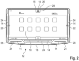
- FIG 2 shows the embodiment according to Figure 1 with various additional functions.
- vehicle functions that affect the left area of the vehicle are set in the area of the left edge area 20 of the first operating and display area 10.
- Vehicle functions that affect the right area of the vehicle are set in the area of the right edge area 22 of the first operating and display area 10. This provides an intuitive control option.
- the window lift function for the left side of the vehicle is set in the left edge area 20 of the first operating and display area 10 by the second operating and display area 14.
- the opening and closing of the window(s) can be controlled by a touch-sensitive slider 24 in the left edge area 20 of the first operating and display area 10 by the second operating and display area 14.
- the window(s) is/are set by a touch-sensitive slider 24 in the right edge area 22 of the first operating and display area 10 by the second operating and display area 14.
- the temperature settings for the heater or air conditioning system can be adjusted in the lower edge area 18 of the first operating and display area 10 by the second operating and display area 14.
- the temperature increase or decrease by the ventilation system on the driver's side can be controlled by a touch-sensitive slider 24 on the left side of the lower edge area 18 of the first operating and display area 10 by the second operating and display area 14.
- the temperature of the ventilation system on the passenger side is adjusted by a touch-sensitive slider 24 on the right side of the lower edge area 18 of the first operating and display area 10 by the second operating and display area 14.
- a touch-sensitive switch 26 provides the option of activating the hazard warning lights.
- corresponding displays 28 can be located near the functions adjustable by the second operating and display area 14. These displays provide information about the functions of the individual slide controls 24 and switches 26. Various menus or active contexts of the infotainment system or navigation system are displayed in the first operating and display area 10. In addition, other information, such as driving information, is also displayed. This includes contents of the instrument cluster, which can be displayed permanently. Displays of the speed, remaining range, gear position, information about turn signals, and/or warning messages are conceivable.
Landscapes
- Engineering & Computer Science (AREA)
- General Engineering & Computer Science (AREA)
- Theoretical Computer Science (AREA)
- Human Computer Interaction (AREA)
- Physics & Mathematics (AREA)
- General Physics & Mathematics (AREA)
- Chemical & Material Sciences (AREA)
- Combustion & Propulsion (AREA)
- Transportation (AREA)
- Mechanical Engineering (AREA)
- User Interface Of Digital Computer (AREA)
- Instrument Panels (AREA)
Claims (9)
- Procédé permettant la commande de fonctions de véhicule, en particulier d'un véhicule automobile, dans lequel les fonctions de véhicule sont réglées au moins partiellement dans une première zone de manipulation et d'affichage (10), dans lequel la première zone de manipulation et d'affichage (10) est au moins partiellement sensible au toucher, dans lequel au moins une seconde zone de manipulation et d'affichage (14) est disposée dans la zone marginale (12) de la première zone de manipulation et d'affichage (10), la seconde zone de manipulation et d'affichage (14) est au moins partiellement sensible au toucher et les fonctions de véhicule sont réglées au moins partiellement dans la seconde zone de manipulation et d'affichage (14), caractérisé en ce que la seconde zone de manipulation et d'affichage (14) est coudée par rapport à la première zone de manipulation et d'affichage (10), dans lequel la première zone de manipulation et d'affichage (10) n'est pas dans un plan comportant la seconde zone de manipulation et d'affichage (14).
- Procédé selon la revendication 1, caractérisé en ce que la seconde zone de manipulation et d'affichage (14) comprend une technologie de capteurs de force afin d'éviter les erreurs de manipulation.
- Procédé selon la revendication 1 ou 2, caractérisé en ce qu'un retour haptique est émis au moins lors du réglage des fonctions de véhicule au moyen de la seconde zone de manipulation et d'affichage (14).
- Procédé selon l'une des revendications 1 à 3, caractérisé en ce qu'un retour acoustique est émis au moins lors du réglage des fonctions de véhicule au moyen de la seconde zone de manipulation et d'affichage (14).
- Procédé selon l'une des revendications 1 à 4, caractérisé en ce que la seconde zone de manipulation et/ou d'affichage (14) est disposée sur la zone marginale supérieure (16) et/ou sur la zone marginale inférieure (18) de la première zone de manipulation et d'affichage (10).
- Procédé selon l'une des revendications 1 à 5, caractérisé en ce que la seconde zone de manipulation et d'affichage (14) est disposée sur la zone marginale gauche (20) et/ou sur la zone marginale droite (22) de la première zone de manipulation et d'affichage (10).
- Procédé selon l'une des revendications 1 à 6, caractérisé en ce que les fonctions de véhicule essentielles sont regroupées dans la seconde zone de manipulation et d'affichage (14).
- Procédé selon la revendication 7, caractérisé en ce qu'au moins une fonction de lève-vitre et/ou un réglage de volume sonore et/ou une sélection de température sont réglés au moyen de la seconde zone de manipulation et d'affichage (14).
- Procédé selon l'une des revendications 1 à 8, caractérisé en ce que les fonctions de véhicule qui concernent la zone gauche du véhicule sont réglées dans la zone de la zone marginale gauche (20) de la première zone de manipulation et d'affichage (10) et en ce que les fonctions de véhicule qui concernent la zone droite du véhicule sont réglées dans la zone de la zone marginale droite (22) de la première zone de manipulation et d'affichage (10).
Applications Claiming Priority (1)
| Application Number | Priority Date | Filing Date | Title |
|---|---|---|---|
| DE102021201376.7A DE102021201376A1 (de) | 2021-02-12 | 2021-02-12 | Verfahren zur Steuerung von Fahrzeugfunktionen |
Publications (2)
| Publication Number | Publication Date |
|---|---|
| EP4043263A1 EP4043263A1 (fr) | 2022-08-17 |
| EP4043263B1 true EP4043263B1 (fr) | 2025-06-04 |
Family
ID=79316979
Family Applications (1)
| Application Number | Title | Priority Date | Filing Date |
|---|---|---|---|
| EP22151074.6A Active EP4043263B1 (fr) | 2021-02-12 | 2022-01-12 | Procédé de commande ds fonctions de véhicule |
Country Status (2)
| Country | Link |
|---|---|
| EP (1) | EP4043263B1 (fr) |
| DE (1) | DE102021201376A1 (fr) |
Families Citing this family (1)
| Publication number | Priority date | Publication date | Assignee | Title |
|---|---|---|---|---|
| DE102023208008A1 (de) | 2023-08-22 | 2025-02-27 | Volkswagen Aktiengesellschaft | System zur Steuerung von Fahrzeugfunktionen eines Kraftfahrzeuges |
Citations (4)
| Publication number | Priority date | Publication date | Assignee | Title |
|---|---|---|---|---|
| US20060238517A1 (en) * | 2005-03-04 | 2006-10-26 | Apple Computer, Inc. | Electronic Device Having Display and Surrounding Touch Sensitive Bezel for User Interface and Control |
| DE102014213429A1 (de) * | 2013-07-18 | 2015-01-22 | Honda Motor Co., Ltd. | Touchpad für eine Benutzer-Fahrzeug-Interaktion |
| DE102014200609A1 (de) * | 2014-01-15 | 2015-07-30 | Bayerische Motoren Werke Aktiengesellschaft | Berührungssensitive Bedienvorrichtung mit Mulde |
| DE102017211524B4 (de) * | 2017-07-06 | 2020-02-06 | Audi Ag | Bedienvorrichtung für ein Kraftfahrzeug und Kraftfahrzeug mit Bedienvorrichtung |
Family Cites Families (6)
| Publication number | Priority date | Publication date | Assignee | Title |
|---|---|---|---|---|
| US8094127B2 (en) * | 2003-07-31 | 2012-01-10 | Volkswagen Ag | Display device |
| DE102010048745A1 (de) * | 2010-10-16 | 2012-04-19 | Volkswagen Ag | Benutzerschnittstelle und Verfahren zum Bedienen einer Benutzerschnittstelle |
| DE102012008681A1 (de) | 2012-04-28 | 2013-10-31 | Audi Ag | Multifunktions-Bedieneinrichtung, insbesondere für ein Kraftfahrzeug |
| EP3040842B1 (fr) | 2015-01-02 | 2019-08-07 | Volkswagen AG | Interface utilisateur et procédé destiné à l'utilisation hybride d'une unité d'affichage d'un moyen de locomotion |
| EP3040808B1 (fr) * | 2015-01-02 | 2019-11-20 | Volkswagen AG | Moyen de transport, interface utilisateur et procédé de définition d'un carreau sur un dispositif d'affichage |
| DE102018210825A1 (de) * | 2018-07-02 | 2020-01-02 | Zf Friedrichshafen Ag | Steuervorrichtung zum Bedienen eines Fahrzeugs, Fahrzeugsystem für ein Fahrzeug und Verfahren zum Bedienen eines Fahrzeugs |
-
2021
- 2021-02-12 DE DE102021201376.7A patent/DE102021201376A1/de active Pending
-
2022
- 2022-01-12 EP EP22151074.6A patent/EP4043263B1/fr active Active
Patent Citations (4)
| Publication number | Priority date | Publication date | Assignee | Title |
|---|---|---|---|---|
| US20060238517A1 (en) * | 2005-03-04 | 2006-10-26 | Apple Computer, Inc. | Electronic Device Having Display and Surrounding Touch Sensitive Bezel for User Interface and Control |
| DE102014213429A1 (de) * | 2013-07-18 | 2015-01-22 | Honda Motor Co., Ltd. | Touchpad für eine Benutzer-Fahrzeug-Interaktion |
| DE102014200609A1 (de) * | 2014-01-15 | 2015-07-30 | Bayerische Motoren Werke Aktiengesellschaft | Berührungssensitive Bedienvorrichtung mit Mulde |
| DE102017211524B4 (de) * | 2017-07-06 | 2020-02-06 | Audi Ag | Bedienvorrichtung für ein Kraftfahrzeug und Kraftfahrzeug mit Bedienvorrichtung |
Also Published As
| Publication number | Publication date |
|---|---|
| EP4043263A1 (fr) | 2022-08-17 |
| DE102021201376A1 (de) | 2022-08-18 |
Similar Documents
| Publication | Publication Date | Title |
|---|---|---|
| EP2885142B1 (fr) | Dispositif de réglage d'un système de climatisation d'un véhicule et procédé correspondant | |
| EP2328783B1 (fr) | Élément de commande pour dispositif d'affichage dans un moyen de transport | |
| EP3085559B1 (fr) | Procede et dispositif de commande d'une climatisation d'un vehicule automobile | |
| DE102010042376A1 (de) | Anzeigevorrichtung für ein Fahrzeug | |
| EP1517224A2 (fr) | Dispositif d'affichage sensible au toucher | |
| DE102016114354A1 (de) | Verfahren und Bedienvorrichtung zum Bedienen einer Klimatisierungsvorrichtung eines Fahrzeugs | |
| DE102015011650B4 (de) | Kraftfahrzeug-Bedienvorrichtung mit Touchscreen-Bedienung | |
| EP2941685B1 (fr) | Procédé de commande et système de commande pour véhicule | |
| DE102008044332A1 (de) | Bedieneinrichtung und Verfahren zur Bedienung | |
| DE102014011118B4 (de) | Verfahren zum Bedienen einer Lichtfunktion von Kraftfahrzeugscheinwerfern und Kraftfahrzeug mit einer Anzeigeeinrichtung und einem Bedienelement für eine Bedienung der Lichtfunktion der Kraftfahrzeugscheinwerfer | |
| DE102010012239A1 (de) | Bedienungs- und Anzeigevorrichtung eines Kraftfahrzeugs | |
| DE102014015403A1 (de) | Bedienvorrichtung zum Steuern von wenigstens einer Funktion von wenigstens einer kraftfahrzeugseitigen Einrichtung | |
| EP4043263B1 (fr) | Procédé de commande ds fonctions de véhicule | |
| DE102019122630A1 (de) | Bedienvorrichtung für ein Kraftfahrzeug | |
| DE102014011119B4 (de) | Kraftfahrzeug mit Bildschirm und Gebläseauslass | |
| DE102009037401A1 (de) | Fahrzeug mit einer Bedieneinrichtung | |
| EP3653427B1 (fr) | Dispositif d'affichage et de commande pour un composant de véhicule | |
| DE102005060605A1 (de) | Bedieneinrichtung für ein Fahrzeug und Set von Bedieneinrichtungen | |
| DE102009039114B4 (de) | Bedienvorrichtung für ein Fahrzeug | |
| DE102016007921A1 (de) | Bedieneinrichtung für ein Funktionselement eines Kraftfahrzeugs und Verfahren zum Bedienen eines Funktionselements | |
| WO2024146834A1 (fr) | Véhicule utilitaire équipé d'un panneau de commande de favoris | |
| DE102014014336A1 (de) | Bedienvorrichtung für ein Kraftfahrzeug | |
| EP4043262A1 (fr) | Dispositif d'affichage et de commande destiné à la commande des fonctions du véhicule | |
| DE102014010302A1 (de) | Mehrfunktionales Bediensystem für ein Kraftfahrzeug | |
| DE102021207897A1 (de) | Bedieneinheit für die Außenspiegel eines Fahrzeugs |
Legal Events
| Date | Code | Title | Description |
|---|---|---|---|
| PUAI | Public reference made under article 153(3) epc to a published international application that has entered the european phase |
Free format text: ORIGINAL CODE: 0009012 |
|
| STAA | Information on the status of an ep patent application or granted ep patent |
Free format text: STATUS: THE APPLICATION HAS BEEN PUBLISHED |
|
| AK | Designated contracting states |
Kind code of ref document: A1 Designated state(s): AL AT BE BG CH CY CZ DE DK EE ES FI FR GB GR HR HU IE IS IT LI LT LU LV MC MK MT NL NO PL PT RO RS SE SI SK SM TR |
|
| STAA | Information on the status of an ep patent application or granted ep patent |
Free format text: STATUS: REQUEST FOR EXAMINATION WAS MADE |
|
| 17P | Request for examination filed |
Effective date: 20230217 |
|
| RBV | Designated contracting states (corrected) |
Designated state(s): AL AT BE BG CH CY CZ DE DK EE ES FI FR GB GR HR HU IE IS IT LI LT LU LV MC MK MT NL NO PL PT RO RS SE SI SK SM TR |
|
| STAA | Information on the status of an ep patent application or granted ep patent |
Free format text: STATUS: EXAMINATION IS IN PROGRESS |
|
| 17Q | First examination report despatched |
Effective date: 20240829 |
|
| REG | Reference to a national code |
Ref country code: DE Ref legal event code: R079 Free format text: PREVIOUS MAIN CLASS: B60K0037060000 Ipc: B60K0035100000 Ref document number: 502022004108 Country of ref document: DE |
|
| GRAP | Despatch of communication of intention to grant a patent |
Free format text: ORIGINAL CODE: EPIDOSNIGR1 |
|
| STAA | Information on the status of an ep patent application or granted ep patent |
Free format text: STATUS: GRANT OF PATENT IS INTENDED |
|
| RIC1 | Information provided on ipc code assigned before grant |
Ipc: G06F 3/048 20130101ALI20250311BHEP Ipc: B60K 35/25 20240101ALI20250311BHEP Ipc: B60K 35/10 20240101AFI20250311BHEP |
|
| INTG | Intention to grant announced |
Effective date: 20250320 |
|
| GRAS | Grant fee paid |
Free format text: ORIGINAL CODE: EPIDOSNIGR3 |
|
| GRAA | (expected) grant |
Free format text: ORIGINAL CODE: 0009210 |
|
| STAA | Information on the status of an ep patent application or granted ep patent |
Free format text: STATUS: THE PATENT HAS BEEN GRANTED |
|
| AK | Designated contracting states |
Kind code of ref document: B1 Designated state(s): AL AT BE BG CH CY CZ DE DK EE ES FI FR GB GR HR HU IE IS IT LI LT LU LV MC MK MT NL NO PL PT RO RS SE SI SK SM TR |
|
| REG | Reference to a national code |
Ref country code: GB Ref legal event code: FG4D Free format text: NOT ENGLISH |
|
| REG | Reference to a national code |
Ref country code: CH Ref legal event code: EP |
|
| REG | Reference to a national code |
Ref country code: DE Ref legal event code: R096 Ref document number: 502022004108 Country of ref document: DE |
|
| REG | Reference to a national code |
Ref country code: IE Ref legal event code: FG4D Free format text: LANGUAGE OF EP DOCUMENT: GERMAN |
|
| P01 | Opt-out of the competence of the unified patent court (upc) registered |
Free format text: CASE NUMBER: APP_29216/2025 Effective date: 20250618 |
|
| REG | Reference to a national code |
Ref country code: NL Ref legal event code: MP Effective date: 20250604 |
|
| PG25 | Lapsed in a contracting state [announced via postgrant information from national office to epo] |
Ref country code: FI Free format text: LAPSE BECAUSE OF FAILURE TO SUBMIT A TRANSLATION OF THE DESCRIPTION OR TO PAY THE FEE WITHIN THE PRESCRIBED TIME-LIMIT Effective date: 20250604 Ref country code: ES Free format text: LAPSE BECAUSE OF FAILURE TO SUBMIT A TRANSLATION OF THE DESCRIPTION OR TO PAY THE FEE WITHIN THE PRESCRIBED TIME-LIMIT Effective date: 20250604 |
|
| REG | Reference to a national code |
Ref country code: LT Ref legal event code: MG9D |
|
| PG25 | Lapsed in a contracting state [announced via postgrant information from national office to epo] |
Ref country code: NO Free format text: LAPSE BECAUSE OF FAILURE TO SUBMIT A TRANSLATION OF THE DESCRIPTION OR TO PAY THE FEE WITHIN THE PRESCRIBED TIME-LIMIT Effective date: 20250904 Ref country code: GR Free format text: LAPSE BECAUSE OF FAILURE TO SUBMIT A TRANSLATION OF THE DESCRIPTION OR TO PAY THE FEE WITHIN THE PRESCRIBED TIME-LIMIT Effective date: 20250905 |
|
| PG25 | Lapsed in a contracting state [announced via postgrant information from national office to epo] |
Ref country code: PL Free format text: LAPSE BECAUSE OF FAILURE TO SUBMIT A TRANSLATION OF THE DESCRIPTION OR TO PAY THE FEE WITHIN THE PRESCRIBED TIME-LIMIT Effective date: 20250604 |
|
| PG25 | Lapsed in a contracting state [announced via postgrant information from national office to epo] |
Ref country code: BG Free format text: LAPSE BECAUSE OF FAILURE TO SUBMIT A TRANSLATION OF THE DESCRIPTION OR TO PAY THE FEE WITHIN THE PRESCRIBED TIME-LIMIT Effective date: 20250604 |
|
| PG25 | Lapsed in a contracting state [announced via postgrant information from national office to epo] |
Ref country code: HR Free format text: LAPSE BECAUSE OF FAILURE TO SUBMIT A TRANSLATION OF THE DESCRIPTION OR TO PAY THE FEE WITHIN THE PRESCRIBED TIME-LIMIT Effective date: 20250604 |
|
| PG25 | Lapsed in a contracting state [announced via postgrant information from national office to epo] |
Ref country code: RS Free format text: LAPSE BECAUSE OF FAILURE TO SUBMIT A TRANSLATION OF THE DESCRIPTION OR TO PAY THE FEE WITHIN THE PRESCRIBED TIME-LIMIT Effective date: 20250904 |
|
| PG25 | Lapsed in a contracting state [announced via postgrant information from national office to epo] |
Ref country code: LV Free format text: LAPSE BECAUSE OF FAILURE TO SUBMIT A TRANSLATION OF THE DESCRIPTION OR TO PAY THE FEE WITHIN THE PRESCRIBED TIME-LIMIT Effective date: 20250604 |
|
| PG25 | Lapsed in a contracting state [announced via postgrant information from national office to epo] |
Ref country code: NL Free format text: LAPSE BECAUSE OF FAILURE TO SUBMIT A TRANSLATION OF THE DESCRIPTION OR TO PAY THE FEE WITHIN THE PRESCRIBED TIME-LIMIT Effective date: 20250604 |
|
| PG25 | Lapsed in a contracting state [announced via postgrant information from national office to epo] |
Ref country code: PT Free format text: LAPSE BECAUSE OF FAILURE TO SUBMIT A TRANSLATION OF THE DESCRIPTION OR TO PAY THE FEE WITHIN THE PRESCRIBED TIME-LIMIT Effective date: 20251006 |
|
| PG25 | Lapsed in a contracting state [announced via postgrant information from national office to epo] |
Ref country code: IS Free format text: LAPSE BECAUSE OF FAILURE TO SUBMIT A TRANSLATION OF THE DESCRIPTION OR TO PAY THE FEE WITHIN THE PRESCRIBED TIME-LIMIT Effective date: 20251004 |
|
| PG25 | Lapsed in a contracting state [announced via postgrant information from national office to epo] |
Ref country code: SM Free format text: LAPSE BECAUSE OF FAILURE TO SUBMIT A TRANSLATION OF THE DESCRIPTION OR TO PAY THE FEE WITHIN THE PRESCRIBED TIME-LIMIT Effective date: 20250604 |
|
| PG25 | Lapsed in a contracting state [announced via postgrant information from national office to epo] |
Ref country code: CZ Free format text: LAPSE BECAUSE OF FAILURE TO SUBMIT A TRANSLATION OF THE DESCRIPTION OR TO PAY THE FEE WITHIN THE PRESCRIBED TIME-LIMIT Effective date: 20250604 |
|
| PG25 | Lapsed in a contracting state [announced via postgrant information from national office to epo] |
Ref country code: EE Free format text: LAPSE BECAUSE OF FAILURE TO SUBMIT A TRANSLATION OF THE DESCRIPTION OR TO PAY THE FEE WITHIN THE PRESCRIBED TIME-LIMIT Effective date: 20250604 |
|
| PG25 | Lapsed in a contracting state [announced via postgrant information from national office to epo] |
Ref country code: SK Free format text: LAPSE BECAUSE OF FAILURE TO SUBMIT A TRANSLATION OF THE DESCRIPTION OR TO PAY THE FEE WITHIN THE PRESCRIBED TIME-LIMIT Effective date: 20250604 |
|
| PG25 | Lapsed in a contracting state [announced via postgrant information from national office to epo] |
Ref country code: IT Free format text: LAPSE BECAUSE OF FAILURE TO SUBMIT A TRANSLATION OF THE DESCRIPTION OR TO PAY THE FEE WITHIN THE PRESCRIBED TIME-LIMIT Effective date: 20250604 |
|
| REG | Reference to a national code |
Ref country code: DE Ref legal event code: R097 Ref document number: 502022004108 Country of ref document: DE |
|
| PGFP | Annual fee paid to national office [announced via postgrant information from national office to epo] |
Ref country code: GB Payment date: 20260126 Year of fee payment: 5 |
|
| PLBE | No opposition filed within time limit |
Free format text: ORIGINAL CODE: 0009261 |
|
| STAA | Information on the status of an ep patent application or granted ep patent |
Free format text: STATUS: NO OPPOSITION FILED WITHIN TIME LIMIT |
|
| PG25 | Lapsed in a contracting state [announced via postgrant information from national office to epo] |
Ref country code: DK Free format text: LAPSE BECAUSE OF FAILURE TO SUBMIT A TRANSLATION OF THE DESCRIPTION OR TO PAY THE FEE WITHIN THE PRESCRIBED TIME-LIMIT Effective date: 20250604 |
|
| PGFP | Annual fee paid to national office [announced via postgrant information from national office to epo] |
Ref country code: DE Payment date: 20260131 Year of fee payment: 5 |
|
| PGFP | Annual fee paid to national office [announced via postgrant information from national office to epo] |
Ref country code: AT Payment date: 20260301 Year of fee payment: 5 |
|
| REG | Reference to a national code |
Ref country code: CH Ref legal event code: L10 Free format text: ST27 STATUS EVENT CODE: U-0-0-L10-L00 (AS PROVIDED BY THE NATIONAL OFFICE) Effective date: 20260416 |
|
| PGFP | Annual fee paid to national office [announced via postgrant information from national office to epo] |
Ref country code: FR Payment date: 20260126 Year of fee payment: 5 |