EP4043281A1 - Carrosserie de véhicule utilitaire et véhicule utilitaire destiné au transport de bobines - Google Patents
Carrosserie de véhicule utilitaire et véhicule utilitaire destiné au transport de bobines Download PDFInfo
- Publication number
- EP4043281A1 EP4043281A1 EP21156397.8A EP21156397A EP4043281A1 EP 4043281 A1 EP4043281 A1 EP 4043281A1 EP 21156397 A EP21156397 A EP 21156397A EP 4043281 A1 EP4043281 A1 EP 4043281A1
- Authority
- EP
- European Patent Office
- Prior art keywords
- receiving trough
- loading space
- movable cover
- utility vehicle
- vehicle body
- Prior art date
- Legal status (The legal status is an assumption and is not a legal conclusion. Google has not performed a legal analysis and makes no representation as to the accuracy of the status listed.)
- Pending
Links
Images



Classifications
-
- B—PERFORMING OPERATIONS; TRANSPORTING
- B60—VEHICLES IN GENERAL
- B60P—VEHICLES ADAPTED FOR LOAD TRANSPORTATION OR TO TRANSPORT, TO CARRY, OR TO COMPRISE SPECIAL LOADS OR OBJECTS
- B60P3/00—Vehicles adapted to transport, to carry or to comprise special loads or objects
- B60P3/035—Vehicles adapted to transport, to carry or to comprise special loads or objects for transporting reel units
-
- B—PERFORMING OPERATIONS; TRANSPORTING
- B60—VEHICLES IN GENERAL
- B60J—WINDOWS, WINDSCREENS, NON-FIXED ROOFS, DOORS, OR SIMILAR DEVICES FOR VEHICLES; REMOVABLE EXTERNAL PROTECTIVE COVERINGS SPECIALLY ADAPTED FOR VEHICLES
- B60J7/00—Non-fixed roofs; Roofs with movable panels, e.g. rotary sunroofs
- B60J7/08—Non-fixed roofs; Roofs with movable panels, e.g. rotary sunroofs of non-sliding type, i.e. movable or removable roofs or panels, e.g. let-down tops or roofs capable of being easily detached or of assuming a collapsed or inoperative position
- B60J7/085—Non-fixed roofs; Roofs with movable panels, e.g. rotary sunroofs of non-sliding type, i.e. movable or removable roofs or panels, e.g. let-down tops or roofs capable of being easily detached or of assuming a collapsed or inoperative position winding up, e.g. for utility vehicles
Definitions
- the present invention relates to a commercial vehicle body for covering a loading space of a commercial vehicle, which is designed to transport at least one coil. Furthermore, the invention relates to a commercial vehicle that is designed to transport at least one coil.
- commercial vehicle includes both motorized vehicles which, based on their design and equipment, are intended for transporting people and goods or for towing trailers, and non-motorized trailers.
- a wound bundle of material such as steel rolls (steel coils) or paper rolls (paper coils), is referred to as a coil.
- a single coil can weigh several tons.
- a single steel coil usually weighs several tons, for example 12 tons.
- the commercial vehicle body used to cover the loading space of the commercial vehicle usually consists of four rectangular side surfaces and a rectangular roof surface.
- the side surfaces and the roof surface are almost at right angles to each other.
- tarpaulin bodies are used in which at least one side wall of the tarpaulin body can be opened and closed by a foldable tarpaulin or the upper roof can be opened (loading via sliding roof between aluminum roof bars).
- the roof will such tarpaulin structures at least partially supported by stanchions which extend in the vertical direction from the bottom of the tarpaulin structure to the roof.
- Roof pillars and roof crossbars are used for stabilization and for the option of opening the roof.
- the technical problem on which the invention is based consists in improving known commercial vehicles for coil transport, in particular with regard to weight, barrier-free loading and traffic safety.
- a commercial vehicle body for covering a loading space of a commercial vehicle such as a truck trailer, which is designed to transport at least one coil.
- the utility vehicle body includes a bulkhead having an arcuate edge portion, and a rear wall spaced apart from the bulkhead in the longitudinal axis direction of the utility vehicle body and having an arcuate edge portion having an arcuate shape similar to that of the bulkhead.
- the commercial vehicle body comprises a movable cover, which extends from the front wall to the rear wall and can be guided along the arcuate edge areas, and a convertible top opening device, which is designed to open the movable cover from a closed state in which the loading space is opened by the movable cover is covered, in an open state, in which the at least one coil can be brought in and out of the hold to move along the arcuate edge regions.
- the arcuate luggage compartment cover can be designed, for example, in the shape of a circular arc or as part of an oval shape.
- the arcuate edge area of the rear wall can have the same arc shape as the edge area of the front wall or can have a different arc shape.
- the movable cover is preferably designed as a foldable tarpaulin, foldable foil or by foldable plastic elements or metal elements.
- the movable cover can also be designed as a roll-up tarpaulin or movable aluminum slat.
- the arched cover ensures traffic safety throughout the winter months due to the lack of snow and ice loads. Due to the curved shape of the movable cover, there is little or no snow load or icing on the luggage compartment cover. The use of an anti-ice system or a de-icing ladder and the like can be dispensed with.
- the commercial vehicle body according to the invention has a solid construction with high operational strength. This is achieved in that the commercial vehicle body according to the invention is designed to be less complex and component-intensive than known commercial vehicle bodies.
- a large number of stanchions, cross-roof bows, aluminum roof rails, slats, load-securing beams, front and rear doors or steel slides can be dispensed with.
- the movable cover can be shifted back and forth between a closed state and an open state.
- the movable cover When open, the movable cover is positioned in such a way that the coil can be brought into the loading space.
- the commercial vehicle structure is preferred designed in such a way that a coil vehicle can be loaded from above using a crane.
- Electric, pneumatic, hydraulic or purely mechanical drives can be used to operate the convertible top opening device, i.e. to move the movable cover.
- the cargo area When open, the introduction of coils into the cargo area is not made more difficult by aluminum roof bars, roof crossbars, sliding stanchions or a tarpaulin roof.
- the cargo area On the other hand, is completely open at the sides and at the top. This prevents damage to components such as a roof rail or guide rails of the side tarpaulins, free-load system or the pushed together (compressed) roof crossbars together with the roof tarpaulin, etc.
- the air resistance of the body during transport can be significantly reduced compared to the known bodies.
- the aerodynamics can be significantly improved by the arcuate frame front together with the arcuate, for example round or oval vehicle structure, and thus savings in fuel costs can be achieved.
- the utility vehicle body has at least one strut.
- the brace is spaced between the bulkhead and the rear wall and has an arcuate edge portion which has a similar arcuate shape to the bulkhead and the rear wall and along which the movable cover is additionally supported.
- the at least one strut provides additional guidance for the movable cover.
- sagging of the movable cover between the bulkhead and the rear wall can be reduced.
- Controlled sliding of the movable cover between the closed condition and the open condition is improved.
- a plurality of struts are preferably evenly aligned in the longitudinal axis direction between the bulkhead and the rear bulkhead.
- the curved edge areas of the strut, the front wall and the rear wall preferably have the same curved shape.
- the at least one strut can be designed, for example, as a plug-in connection of aluminum, steel, plastic, glass fiber or wooden struts.
- the at least one strut has a strut that extends into the loading space in such a way that it creates a support for the at least one coil within the loading space.
- the strut of the at least one strut which extends into the loading space, creates a contact surface for a coil.
- the strut is designed in such a way that it can be firmly connected to the floor of the loading space. In this way it is possible to use the contact surface as an additional anti-displacement device for a coil within the hold. In this way, a form-fit load securing can be achieved.
- the coil can be lashed against the strut with lashing straps. The coil is thus secured against longitudinal movement in the hold.
- the contact surface can be the side surface of steel plug-in stanchions that can be inserted into receptacles in the floor of the hold.
- the arcuate edge region of the strut and the strut extending into the loading space are preferably connected to one another.
- the convertible top opening device has a swivel arm and a drive.
- the swivel arm can be connected to the movable cover at a swivel arm end and is rotatably mounted on a swivel arm head area.
- the driver is coupled to the swing arm head portion and is configured to rotate the swing arm and, through the rotation, move the movable cover back and forth between the closed condition and the open condition.
- the convertible top opening device has a swivel arm and a drive in the area of the bulkhead and/or in the area of the rear wall. The swivel arm end moves along the arcuate edge area when the swivel arm rotates.
- a swing arm is a simple and reliable method of moving the movable cargo area cover between the closed position and the open position.
- the swivel arm only has to be rotated around one axis. No translational movements of the swivel arm are necessary.
- the convertible top opening device can have a swivel arm in the area of the front wall and/or the rear wall or a swivel arm in the area of the front wall and/or the rear wall.
- the swivel arm is mounted in such a way that the end of the swivel arm moves along the arcuate edge area of the front wall or the rear wall.
- the swivel arm In the area of the rotatable mounting of the swivel arm, the swivel arm is connected to a drive with which the Swivel arm can be rotated.
- the drives that are connected to the swivel arms can be designed in such a way that they can run synchronously with one another and thus move the movable cover in a controlled manner.
- the drive of the top opening device is a rack and pinion drive, which generates the rotation of the swivel arm by linear displacement of a toothed rack via a gear wheel connected to the swivel arm, or in which the drive has a worm or bevel gear.
- a rack and pinion drive can be used as a simple and reliable drive.
- the linear displacement of the rack of the rack and pinion drive can be implemented, for example, with a cylinder (hydraulic, pneumatic, electric, etc.), a manual hydraulic pump, an electrohydraulic pump, a pneumatic pump, a pneumatic compressor or a manual gear.
- a drive can also be used, for example, which has a worm gear or bevel gear for moving the swivel arm.
- the toothed wheel of the rack and pinion drive can be designed, for example, in the form of a half toothed wheel which is integrally connected to the swivel arm.
- the movable cover has a stiffened edge area which is connected to the top opening device. Furthermore, the front wall and the rear wall have along the arcuate edge areas a sliding strip which is designed to allow the stiffened edge area of the movable cover to slide thereon and/or a guide rail which is designed to allow the stiffened edge area of the movable cover to be guided thereon and /or a cable or chain guide designed to guide the movable cover along the arcuate edge areas.
- the movable cover can be stiffened in the edge area.
- a stiffening can be created, for example, using a stiff material in the edge area or by using ropes, chains, etc.
- the movable cover with a stiffening member be provided.
- this can be a metal bar that is connected to the movable cover from the front wall to the rear wall in the edge area of the movable cover.
- the convertible top opening device transfers the force in this area to the movable cover. If the movable cover is sufficiently rigid, it is also possible to dispense with stiffening the edge area.
- the curved edge areas of the front wall and rear wall can be provided with sliding strips and/or guide rails and/or cables and/or chains.
- guide rails are fastened to the curved edge area of the bulkhead and rear wall.
- the movable cover is provided with corresponding connecting members or rollers which engage in the guide rail.
- a convertible top opening device can also be used, in which the movable cover is guided along the curved edge regions with a cable or chain guide.
- a cable guide can be used, as is currently used in the sliding roofs, model Galoppino from Cramaro.
- the movable cover In the front and rear area of the commercial vehicle body, the movable cover can be secured, for example, via an overlap with an expander cable and as a result of aluminum bars integrated into the movable cover several times at intervals.
- the at least one strut has a sliding strip and/or a guide rail and/or a cable/chain guide along the curved edge area.
- a slide strip and/or guide rails may also be located in the arcuate edge portion of the one or more struts. This further improves the low-friction and/or controlled guidance of the movable cover.
- the technical problem on which the invention is based is also solved by a commercial vehicle with a loading space which is designed to transport at least one coil a receiving trough with two receiving trough side walls arranged in the area of a luggage compartment floor.
- the two receptacle side walls extend obliquely upwards in opposite horizontal directions.
- the receiving trough side walls protrude upwards over the load compartment floor of the load compartment with an overhang.
- the protruding receiving trough side walls can absorb deformation energy and thus protect the floor of the loading space and the components of the commercial vehicle underneath from damage by the coil, e.g. B. protect against plastic deformation by swiftly depositing the coil during a loading process as a result of excessive force application / force in the components of the commercial vehicle or in the vehicle frame structure resulting from a sudden point load. For example, such damage can result from a coil being lowered or falling down too quickly.
- the receiving trough is designed in such a way that it can be covered in such a way that a flat support surface is created between the overhanging ends of the receiving trough side walls. In this way, loads other than a coil can also be transported.
- the luggage compartment floor extending next to the receiving trough can also be covered in order to compensate for the difference in height of the overhang of the receiving trough side wall and to obtain a level floor surface over the entire luggage compartment.
- the receiving trough side wall is formed, at least in regions, by an upper chord of a longitudinal frame member of the utility vehicle.
- the upper flanges of the longitudinal frame members are formed integrally with the web of the longitudinal frame member, in particular welded.
- the upper chord is placed at an angle or tilted.
- the top chords preferably form the cantilevered overhang of the receiving trough side walls over the loading space floor. As a result of this overhang, there is a coil rest on the main longitudinal member of the frame.
- the load or the mass/weight force is introduced directly into the frame construction and the coil to be transported is preferably supported on the vehicle frame via the upper flange.
- the top chord can also be releasably connected to the web of the longitudinal frame member, for example in the form of a plug-in connection.
- this embodiment differs from known coil semi-trailers in which the load or force is introduced into a coil trough which is not the top chord and which is clamped laterally in or between the main beams.
- the at least regionally integral design of the receiving trough side wall and upper flange of the frame side member according to the invention results in an optimized flow of forces and enormous operational strength.
- the upper chords of the longitudinal frame members protrude approx. 50 mm over the side steps, ie the load compartment floor.
- the side walls of the receiving trough protrude more clearly over the floor of the luggage compartment / step area.
- This allows a coil with a larger diameter to be loaded and guided in an optimized manner.
- the protruding overhang is increased and the coil with a larger diameter (e.g. paper coil) rests on these top chords.
- the weight force is introduced directly into the vehicle frame, in particular the main frame longitudinal members. Consequently, the coil does not rest on the bottom of the receiving trough, but on the side walls of the receiving trough (in particular the top flange). The forces are thus introduced into the vehicle frame and not exclusively into the coil trough floor.
- the upper chord is preferably welded to the web of the longitudinal frame member.
- Such a one-piece design of the longitudinal members with the side wall of the receiving trough represents a design that is significantly optimized in terms of operational stability due to the components that are continuously welded by welding. As a result, the material thicknesses and material cross sections can be extensively reduced. As a result, weight saving, an increase in cargo weight without exceeding the gross vehicle weight rating, and fuel economy can be achieved.
- a receiving trough side wall extension is preferably attached to the top chord downwards.
- the receiving trough side wall extension can be welded to the upper chord, for example. Alternatively, it can also be connected to the upper chord with a detachable connection.
- the top chord and the extension are preferably canted. This creates a receiving area for screen printing plates, for example, which can be inserted into the side wall of the receiving cavity.
- the receiving trough side wall comprises the upper chord in the upper area and an accommodating trough side wall extension in the lower area.
- a further trough side wall extension can be attached, for example welded, to the upper chord at an angle upwards, through which the trough side wall is extended upwards.
- the receiving trough preferably extends in the longitudinal direction of the utility vehicle, i.e. from a front area of the utility vehicle to a rear area of the utility vehicle.
- the well sidewalls can then be referred to as left and right well sidewalls.
- the left receiver well side wall extends laterally obliquely left-upper
- the right receiver well side wall extends laterally obliquely right-upper.
- the left and right receptacle sidewalls extend from the front end to a rear end of the cargo space.
- the receiving trough can also only extend over a partial area between the front end and a rear end of the loading space.
- the receiving trough is preferably designed with a receiving trough base which lies between the two receiving trough side walls.
- the receiving trough can be designed without a base or the two receiving trough side walls can also be connected directly to one another.
- Corresponding the receiving trough can have a pointed or triangular configuration.
- the receiving trough base is preferably welded to the receiving trough side wall or is designed in one piece.
- the receiving trough base can also be releasably connected to the receiving trough side wall, for example with a plug-in connection.
- the geometry of the receiving trough is selected in such a way that the coil to be transported rests against the two receiving trough side walls when it is placed in the receiving trough. A positive fit is achieved by the coil resting against the side walls of the receiving trough.
- the load can also be lashed down with lashing straps.
- the lashing straps are fastened, for example, to fastening hooks, lashing brackets, lashing eyes, transport rings, lashing hooks, lashing rails distributed in the longitudinal direction.
- a frictional connection is achieved by lashing it down.
- additional friction-enhancing materials e.g. B. screen printing plates, anti-slip mats, anti-slip coating can be used.
- edges can be provided in the side wall of the receiving recess, which form a receiving area for the screen printing plates.
- the receiving trough is preferably positioned in such a way that an optimal weight distribution is achieved directly between the wheels and above the respective axle unit/axle body.
- the permissible axle assembly load and the saddle load/support load are taken into account.
- the stability of the entire vehicle construction and the operational strength can be increased by the receiving trough according to the invention.
- the receiving trough is preferably welded to the load compartment floor.
- a ladder can be attached to the side of the utility vehicle for simplified entry into the loading space and onto the intended step/loading space floor. To increase traffic safety, this access ladder can be attached to the side of the vehicle facing away from traffic.
- the utility vehicle is a truck trailer and includes a front frame module and a main frame module having front and rear ends.
- the front frame module is attached to the front end.
- the two frame rails extend from the front end to the rear end at a distance from one another in the transverse direction and between the two frame side members is the receiving trough.
- the two well sidewalls are left and right well sidewalls.
- the left receiver well side wall extends laterally obliquely left-upper, and the right receiver well side wall extends laterally obliquely right-upper.
- the left and right side wall of the receiving trough protrudes upwards over the luggage compartment floor with the overhang.
- the two receiving trough side walls are each formed, at least in regions, by an upper chord of the two longitudinal frame members.
- the receiving trough side walls protrude, measured in the vertical direction as a function of the coil size, with an overhang in the range of preferably approx. 1 mm to approx. 400 mm, more preferably in the range of approx. 10 mm to approx. 200 mm, more preferably in Range from about 20 mm to about 100 mm, more preferably in the range from about 30 mm to about 60 mm above the cargo area floor.
- An embodiment of the receiving trough with such an oversize represents a reliable guidance of the coil during loading. It also ensures that the forces acting on the commercial vehicle through the coil are introduced directly into the frame and other components, such as the load compartment floor, through the protruding receiving trough side walls are protected.
- the receiving trough has insertion holes which are aligned in the direction of the longitudinal axis and are designed to receive struts.
- the insertion holes are designed so that struts can be inserted into them, preferably vertically. These struts can be used to create a system within the cargo hold along with form-fitting load securing for the coil.
- the receiving trough side walls each have a detachable section which is located at least partially above the floor of the loading space.
- the detachable section is designed, for example, in the form of a plug connection, screw connection or other detachable connection option.
- the utility vehicle further comprises a utility vehicle body including a tonneau cover extending from the front end to the rear end of the tonneau and transversely from a left-hand edge to a right-hand edge of the tonneau cover.
- the coil to be transported can be protected against external influences by the commercial vehicle body.
- the utility vehicle body is an inventive utility vehicle body according to the above aspect.
- a truck trailer which is an arcuate vehicle frame front module as the front frame module, as is known from FIG EP 2 886 424 B1 is known, used.
- a vehicle frame front module has: a front area facing a towing vehicle, a rear area facing away from the towing vehicle, a first vertical web with a first straight area and a first curved area, and a second vertical web with a second straight area and a second curved area .
- the first arcuate portion and the second arcuate portion are connected to each other.
- the first straight portion and the second straight portion are divergent in a direction from the front portion to the rear portion.
- the first vertical web and the second vertical web are each connected to one of the two side rails of the main frame module.
- the direction of the longitudinal axis of the commercial vehicle is referred to below as the front-rear direction.
- the transverse direction of the commercial vehicle is referred to as the left-right direction.
- FIG. 1 1 is a perspective view of an exemplary embodiment of a utility vehicle body 1 according to the present invention.
- the commercial vehicle body 1 is the body of a truck trailer 3 .
- a front wall 5 which has an arcuate edge area 6 .
- a rear wall 7 with the curved edge area 8.
- the loading space 2 In the loading space 2 there is a coil 4.
- a strut 10 Between the front wall 5 and the rear wall 7 is located there is also a strut 10.
- the strut 10 has arcuate struts 11 in the edge region.
- the strut 10 has vertical struts 20 which extend vertically through the hold 2 from the floor of the hold 2 upwards.
- a swivel arm 13 is located in front of the end wall 5 and behind the rear wall 7.
- the swivel arm 13 is rotatably mounted in the region of the swivel arm head region 15 and is connected to a rack and pinion drive.
- the rack and pinion drive comprises a rack 17 and a half gear 18 integral with the swivel arm 13.
- the rack 17 can be connected, for example, to a hydraulic cylinder 24 (in Fig 1 not shown) can be reciprocated.
- the pivot arm end 14 of the pivot arm 13 protrudes over the arcuate edge area 6 of the end wall 5 or the arcuate edge area 8 of the rear wall 7 out.
- a movable cover 9 covering the loading space 2 is in 1 Not shown.
- FIG. 2 is another perspective view of the in 1 commercial vehicle structure shown.
- a movable cover 9 is shown.
- the movable cover 9 is connected to a rod 22 in its edge area.
- the sliding strips 21 are located on the curved edge area 6 of the front wall 5, the curved edge area 8 of the rear wall 7 and the curved edge area 11 of the strut 10.
- the swivel arms 13 are connected to the rod 22 in the area of the two swivel arm ends 14 .
- the rack 17 is connected to a hydraulic cylinder 24 .
- a ladder 25 is located on the side of the truck trailer 3.
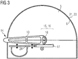
- FIG. 3 is a rear view of the in 1 shown commercial vehicle body 1.
- the swivel arm 13 Integrally with the swivel arm 13, half a gear 18 is performed. The half gear 18 meshes with the toothed rack 17 .
- the rack 17 is connected to the hydraulic cylinder 24 .
- the swivel arm 13 can be rotated in such a way that the end 14 of the swivel arm moves along the arcuate edge area 6 .
- a sliding strip 21 is located on the curved edge area 6 .
- a guide rail 23 can also be located on the curved edge area 6 .
- a cable or chain guide can also be located along the arcuate area.
- 4 1 is a perspective view of an exemplary embodiment of a truck trailer 3 according to the present invention.
- 4 shows a truck trailer 3 with a front frame module 30 and a main frame module 31.
- a coil 4 which is placed in a receiving trough 35.
- the receiving trough 35 runs from the front end 32 of the main frame module 31 to the rear end 33 of the main frame module 31.
- the receiving trough 35 runs between two longitudinal members 34, with the sloping top chords 39 of these longitudinal members 34 protruding over the luggage compartment floor 38 and representing an overhang. Viewed in the transverse direction, the receiving trough 35 has a receiving trough base 36 in the middle.
- the receiving trough can also taper to a point without a receiving trough base 36 .
- two receiving trough side walls 37 extend obliquely upwards.
- the two receiving trough side walls 37 comprise a receiving trough side wall extension 47 extending up to the upper chord 39 and the upper chord 39.
- the upper chord 39 is therefore a component of the receiving trough side wall 37.
- the upper chord 39 protrudes over the loading space floor (the tread) 38. From the front end 32 to the rear end 33 of the main frame module 31, this results in a projecting overhang of a right and a left receiving recess side wall 37.
- a luggage compartment cover (in the 4 not shown) can extend from the front end 32 to a rear end 33 of the cargo space 2 and in the transverse direction from a left-hand edge region 41 to a right-hand edge region 42 of the cargo space 2 .
- FIG 5 is a perspective view of the receiving trough 35 of FIG 4 truck trailer shown.
- the receiving trough floor 36 is recessed in relation to the loading space floor 38 .
- the upper chords 39 of the longitudinal frame members 34 form the upper region of the side walls 37 of the receiving trough.
- the receiving trough side walls 37 include a receiving trough side wall extension 47 which connects the upper chord 39 to the receiving trough base 36 .
- the receiving trough side wall 37 thus includes the upper chord 39 and the receiving trough side wall extension 37.
- the upper chords 39 protrude obliquely upwards over the loading space floor 38.
- the receiving trough side walls 37 have insertion holes 44 .
- the insertion holes 44 are formed so that stays can be inserted into them perpendicularly.
- An insert plate 48 such as a screen printing plate, is shown inserted into the receiving well side wall 37 (in Fig 4 no insert plate is shown).
- Fig. 12 is a sectional view along line AA in Fig figure 5 .
- the longitudinal frame member 34 has an upper chord 39 and a lower chord 45 .
- the upper chord 39 and the lower chord 45 are welded to the web 46 of the longitudinal frame member 34 .
- the upper chord 39 is welded at an angle to the frame longitudinal member web 34 and forms part of the (likewise at an angle) receiving trough side wall 37 .
- the receiving trough side wall 37 is thus formed in some areas by the upper chord 39 .
- the upper chord 39 protrudes obliquely upwards in the direction of the Load compartment floor 38 with the overhang Ü also.
- the upper chord 39 is canted in the downward direction.
- a receiving trough side wall extension 47 is welded to the upper chord 39 .
- the receiving trough side wall extension 47 is also canted and is connected to the receiving trough base 36 at the lower end. Due to the edging in the upper chord 39 and in the receiving trough side wall extension 47, a receiving area for an insert plate, such as a screen printing plate, is created.
- a coil 4 rests on the receiving trough side wall 37 .
- the receptacle side wall 37 and the receptacle bottom 36 are supported on the cross members 43 arranged at regular intervals from front to rear.
- the air resistance of the body during transport can be reduced in comparison to the known bodies. A saving in fuel expenses can thus be achieved.
- the curved cover continuously ensures road safety in the winter months as a result of a lack of snow and ice loads, so there is no snow load or icing on the curved loading space cover.
- the variety of components is low and the risk of permanent damage as a result of free loading space access is significantly reduced.
Landscapes
- Engineering & Computer Science (AREA)
- Mechanical Engineering (AREA)
- Health & Medical Sciences (AREA)
- Public Health (AREA)
- Transportation (AREA)
- Fittings On The Vehicle Exterior For Carrying Loads, And Devices For Holding Or Mounting Articles (AREA)
Priority Applications (1)
| Application Number | Priority Date | Filing Date | Title |
|---|---|---|---|
| EP21156397.8A EP4043281A1 (fr) | 2021-02-10 | 2021-02-10 | Carrosserie de véhicule utilitaire et véhicule utilitaire destiné au transport de bobines |
Applications Claiming Priority (1)
| Application Number | Priority Date | Filing Date | Title |
|---|---|---|---|
| EP21156397.8A EP4043281A1 (fr) | 2021-02-10 | 2021-02-10 | Carrosserie de véhicule utilitaire et véhicule utilitaire destiné au transport de bobines |
Publications (1)
| Publication Number | Publication Date |
|---|---|
| EP4043281A1 true EP4043281A1 (fr) | 2022-08-17 |
Family
ID=74591761
Family Applications (1)
| Application Number | Title | Priority Date | Filing Date |
|---|---|---|---|
| EP21156397.8A Pending EP4043281A1 (fr) | 2021-02-10 | 2021-02-10 | Carrosserie de véhicule utilitaire et véhicule utilitaire destiné au transport de bobines |
Country Status (1)
| Country | Link |
|---|---|
| EP (1) | EP4043281A1 (fr) |
Citations (6)
| Publication number | Priority date | Publication date | Assignee | Title |
|---|---|---|---|---|
| CA1243062A (fr) * | 1985-04-09 | 1988-10-11 | Daniel W. Hawken | Bache pour benne de camion |
| FR2689827A1 (fr) * | 1992-04-14 | 1993-10-15 | Couturier Sa Transports | Dispositif support en vue du transport d'objets de forme d'enveloppe cylindrique de révolution tels des rouleaux de produits sidérurgiques. |
| DE10312638A1 (de) * | 2003-03-21 | 2004-10-07 | Sommer Fahrzeugbau Gmbh & Co. Kg | Verfahren und Vorrichtung zur Ladungssicherung |
| EP2886424A1 (fr) | 2013-12-19 | 2015-06-24 | Helmut Fliegl | Module frontal de châssis en forme d'arc pour remorques de véhicules |
| US20150224911A1 (en) * | 2008-05-09 | 2015-08-13 | Agri-Cover, Inc. | Roll-up Tarp Apparatus |
| US10377293B1 (en) * | 2017-05-24 | 2019-08-13 | Richard J. Coughtry | Container covering deployment system |
-
2021
- 2021-02-10 EP EP21156397.8A patent/EP4043281A1/fr active Pending
Patent Citations (6)
| Publication number | Priority date | Publication date | Assignee | Title |
|---|---|---|---|---|
| CA1243062A (fr) * | 1985-04-09 | 1988-10-11 | Daniel W. Hawken | Bache pour benne de camion |
| FR2689827A1 (fr) * | 1992-04-14 | 1993-10-15 | Couturier Sa Transports | Dispositif support en vue du transport d'objets de forme d'enveloppe cylindrique de révolution tels des rouleaux de produits sidérurgiques. |
| DE10312638A1 (de) * | 2003-03-21 | 2004-10-07 | Sommer Fahrzeugbau Gmbh & Co. Kg | Verfahren und Vorrichtung zur Ladungssicherung |
| US20150224911A1 (en) * | 2008-05-09 | 2015-08-13 | Agri-Cover, Inc. | Roll-up Tarp Apparatus |
| EP2886424A1 (fr) | 2013-12-19 | 2015-06-24 | Helmut Fliegl | Module frontal de châssis en forme d'arc pour remorques de véhicules |
| US10377293B1 (en) * | 2017-05-24 | 2019-08-13 | Richard J. Coughtry | Container covering deployment system |
Similar Documents
| Publication | Publication Date | Title |
|---|---|---|
| EP3268257B1 (fr) | Dispositif de transport levable | |
| DE10124283C1 (de) | Dachhaut | |
| DE3200792A1 (de) | "fahrzeug-anhaenger" | |
| EP3699058B1 (fr) | Agencement d'un véhicule ferroviaire et dispositif support | |
| EP1560730B1 (fr) | Vehicule a conteneurs de chargement ou plate-formes de chargement | |
| DE102013201003A1 (de) | Längsgurt für Schiebeverdeckstruktur und Schiebeverdeckstruktur | |
| DE102004018910A1 (de) | Flurfolgefahrzeug | |
| DE69308971T2 (de) | Umstellbarer, doppelter Boden für Kraftfahrzeuge in einer Transporteinheit | |
| EP3699057A1 (fr) | Dispositif porteur élevable | |
| DE4237410C2 (de) | Pritschenaufbau für LKW-Wechselbehälter und Festaufbauten | |
| DE102019123202B4 (de) | Fahrzeugtransporter | |
| EP4043281A1 (fr) | Carrosserie de véhicule utilitaire et véhicule utilitaire destiné au transport de bobines | |
| DE10061954A1 (de) | Hecktransportsystem | |
| DE102004064026B4 (de) | Vorrichtung zum Beladen eines Laderaumes von Fahrzeugen | |
| DE8810497U1 (de) | Karosserie für ein Kraftfahrzeug oder einen Anhänger | |
| DE19542816C2 (de) | Transportfahrzeug | |
| EP3599119B1 (fr) | Structure de bâche résistante à l'humidité | |
| EP0379909A2 (fr) | Véhicule utilitaire à plateau de chargement mobile | |
| DE3723452A1 (de) | Schiebeverdeckgestell fuer lastfahrzeuge | |
| DE102015111842B4 (de) | Laderaumaufbau | |
| DE69504553T2 (de) | Einheit für kombinierten Transport, selbstragend und verwandelbar für den kombinierten Schiene/Strasse-Transport von Fracht und Fahrzeugen | |
| DE69400934T2 (de) | Vorrichtung zum Abnehmen der Plane eines Fahrzeugs und zum Räumen der Ladefläche von allen Aufbauten | |
| EP1479562A2 (fr) | Véhicule pour le transport de marchandises et dispositif pour la fixation de la charge | |
| DE20220225U1 (de) | Fahrzeug mit Ladeboxen oder Ladeflächen | |
| DE19950553C2 (de) | LKW-Hubvorrichtung für unterfahrbare Wechselbehälter |
Legal Events
| Date | Code | Title | Description |
|---|---|---|---|
| PUAI | Public reference made under article 153(3) epc to a published international application that has entered the european phase |
Free format text: ORIGINAL CODE: 0009012 |
|
| STAA | Information on the status of an ep patent application or granted ep patent |
Free format text: STATUS: THE APPLICATION HAS BEEN PUBLISHED |
|
| AK | Designated contracting states |
Kind code of ref document: A1 Designated state(s): AL AT BE BG CH CY CZ DE DK EE ES FI FR GB GR HR HU IE IS IT LI LT LU LV MC MK MT NL NO PL PT RO RS SE SI SK SM TR |
|
| STAA | Information on the status of an ep patent application or granted ep patent |
Free format text: STATUS: REQUEST FOR EXAMINATION WAS MADE |
|
| 17P | Request for examination filed |
Effective date: 20230208 |
|
| RBV | Designated contracting states (corrected) |
Designated state(s): AL AT BE BG CH CY CZ DE DK EE ES FI FR GB GR HR HU IE IS IT LI LT LU LV MC MK MT NL NO PL PT RO RS SE SI SK SM TR |
|
| STAA | Information on the status of an ep patent application or granted ep patent |
Free format text: STATUS: EXAMINATION IS IN PROGRESS |
|
| 17Q | First examination report despatched |
Effective date: 20231018 |
|
| GRAP | Despatch of communication of intention to grant a patent |
Free format text: ORIGINAL CODE: EPIDOSNIGR1 |
|
| STAA | Information on the status of an ep patent application or granted ep patent |
Free format text: STATUS: GRANT OF PATENT IS INTENDED |
|
| INTG | Intention to grant announced |
Effective date: 20260130 |