EP4043364A2 - Behälter zur aufnahme einer flüssigkeit und verfahren damit - Google Patents
Behälter zur aufnahme einer flüssigkeit und verfahren damit Download PDFInfo
- Publication number
- EP4043364A2 EP4043364A2 EP22160688.2A EP22160688A EP4043364A2 EP 4043364 A2 EP4043364 A2 EP 4043364A2 EP 22160688 A EP22160688 A EP 22160688A EP 4043364 A2 EP4043364 A2 EP 4043364A2
- Authority
- EP
- European Patent Office
- Prior art keywords
- liquid vessel
- engageable
- liquid
- narrow space
- engaged
- Prior art date
- Legal status (The legal status is an assumption and is not a legal conclusion. Google has not performed a legal analysis and makes no representation as to the accuracy of the status listed.)
- Granted
Links
Images


Classifications
-
- B—PERFORMING OPERATIONS; TRANSPORTING
- B65—CONVEYING; PACKING; STORING; HANDLING THIN OR FILAMENTARY MATERIAL
- B65D—CONTAINERS FOR STORAGE OR TRANSPORT OF ARTICLES OR MATERIALS, e.g. BAGS, BARRELS, BOTTLES, BOXES, CANS, CARTONS, CRATES, DRUMS, JARS, TANKS, HOPPERS, FORWARDING CONTAINERS; ACCESSORIES, CLOSURES, OR FITTINGS THEREFOR; PACKAGING ELEMENTS; PACKAGES
- B65D7/00—Containers having bodies formed by interconnecting or uniting two or more rigid, or substantially rigid, components made wholly or mainly of metal
- B65D7/12—Containers having bodies formed by interconnecting or uniting two or more rigid, or substantially rigid, components made wholly or mainly of metal characterised by wall construction or by connections between walls
- B65D7/24—Containers having bodies formed by interconnecting or uniting two or more rigid, or substantially rigid, components made wholly or mainly of metal characterised by wall construction or by connections between walls collapsible, e.g. with all parts detachable
-
- B—PERFORMING OPERATIONS; TRANSPORTING
- B41—PRINTING; LINING MACHINES; TYPEWRITERS; STAMPS
- B41B—MACHINES OR ACCESSORIES FOR MAKING, SETTING, OR DISTRIBUTING TYPE; TYPE; PHOTOGRAPHIC OR PHOTOELECTRIC COMPOSING DEVICES
- B41B11/00—Details of, or accessories for, machines for mechanical composition using matrices for individual characters which are selected and assembled for type casting or moulding
- B41B11/52—Moulding or casting devices or associated mechanisms
- B41B11/54—Moulds; Liners therefor
-
- B—PERFORMING OPERATIONS; TRANSPORTING
- B65—CONVEYING; PACKING; STORING; HANDLING THIN OR FILAMENTARY MATERIAL
- B65D—CONTAINERS FOR STORAGE OR TRANSPORT OF ARTICLES OR MATERIALS, e.g. BAGS, BARRELS, BOTTLES, BOXES, CANS, CARTONS, CRATES, DRUMS, JARS, TANKS, HOPPERS, FORWARDING CONTAINERS; ACCESSORIES, CLOSURES, OR FITTINGS THEREFOR; PACKAGING ELEMENTS; PACKAGES
- B65D7/00—Containers having bodies formed by interconnecting or uniting two or more rigid, or substantially rigid, components made wholly or mainly of metal
- B65D7/02—Containers having bodies formed by interconnecting or uniting two or more rigid, or substantially rigid, components made wholly or mainly of metal characterised by shape
- B65D7/04—Containers having bodies formed by interconnecting or uniting two or more rigid, or substantially rigid, components made wholly or mainly of metal characterised by shape of curved cross-section, e.g. cans of circular or elliptical cross-section
-
- B—PERFORMING OPERATIONS; TRANSPORTING
- B65—CONVEYING; PACKING; STORING; HANDLING THIN OR FILAMENTARY MATERIAL
- B65D—CONTAINERS FOR STORAGE OR TRANSPORT OF ARTICLES OR MATERIALS, e.g. BAGS, BARRELS, BOTTLES, BOXES, CANS, CARTONS, CRATES, DRUMS, JARS, TANKS, HOPPERS, FORWARDING CONTAINERS; ACCESSORIES, CLOSURES, OR FITTINGS THEREFOR; PACKAGING ELEMENTS; PACKAGES
- B65D7/00—Containers having bodies formed by interconnecting or uniting two or more rigid, or substantially rigid, components made wholly or mainly of metal
- B65D7/02—Containers having bodies formed by interconnecting or uniting two or more rigid, or substantially rigid, components made wholly or mainly of metal characterised by shape
- B65D7/06—Containers having bodies formed by interconnecting or uniting two or more rigid, or substantially rigid, components made wholly or mainly of metal characterised by shape of polygonal cross-section, e.g. tins, boxes
-
- B—PERFORMING OPERATIONS; TRANSPORTING
- B65—CONVEYING; PACKING; STORING; HANDLING THIN OR FILAMENTARY MATERIAL
- B65D—CONTAINERS FOR STORAGE OR TRANSPORT OF ARTICLES OR MATERIALS, e.g. BAGS, BARRELS, BOTTLES, BOXES, CANS, CARTONS, CRATES, DRUMS, JARS, TANKS, HOPPERS, FORWARDING CONTAINERS; ACCESSORIES, CLOSURES, OR FITTINGS THEREFOR; PACKAGING ELEMENTS; PACKAGES
- B65D7/00—Containers having bodies formed by interconnecting or uniting two or more rigid, or substantially rigid, components made wholly or mainly of metal
- B65D7/12—Containers having bodies formed by interconnecting or uniting two or more rigid, or substantially rigid, components made wholly or mainly of metal characterised by wall construction or by connections between walls
- B65D7/22—Containers having bodies formed by interconnecting or uniting two or more rigid, or substantially rigid, components made wholly or mainly of metal characterised by wall construction or by connections between walls with double walls, e.g. double end walls
-
- B—PERFORMING OPERATIONS; TRANSPORTING
- B65—CONVEYING; PACKING; STORING; HANDLING THIN OR FILAMENTARY MATERIAL
- B65D—CONTAINERS FOR STORAGE OR TRANSPORT OF ARTICLES OR MATERIALS, e.g. BAGS, BARRELS, BOTTLES, BOXES, CANS, CARTONS, CRATES, DRUMS, JARS, TANKS, HOPPERS, FORWARDING CONTAINERS; ACCESSORIES, CLOSURES, OR FITTINGS THEREFOR; PACKAGING ELEMENTS; PACKAGES
- B65D90/00—Component parts, details or accessories for large containers
- B65D90/02—Wall construction
- B65D90/028—Wall construction hollow-walled, e.g. double-walled with spacers
-
- B—PERFORMING OPERATIONS; TRANSPORTING
- B65—CONVEYING; PACKING; STORING; HANDLING THIN OR FILAMENTARY MATERIAL
- B65D—CONTAINERS FOR STORAGE OR TRANSPORT OF ARTICLES OR MATERIALS, e.g. BAGS, BARRELS, BOTTLES, BOXES, CANS, CARTONS, CRATES, DRUMS, JARS, TANKS, HOPPERS, FORWARDING CONTAINERS; ACCESSORIES, CLOSURES, OR FITTINGS THEREFOR; PACKAGING ELEMENTS; PACKAGES
- B65D90/00—Component parts, details or accessories for large containers
- B65D90/02—Wall construction
- B65D90/08—Interconnections of wall parts; Sealing means therefor
-
- C—CHEMISTRY; METALLURGY
- C03—GLASS; MINERAL OR SLAG WOOL
- C03B—MANUFACTURE, SHAPING, OR SUPPLEMENTARY PROCESSES
- C03B18/00—Shaping glass in contact with the surface of a liquid
- C03B18/02—Forming sheets
- C03B18/16—Construction of the float tank; Use of material for the float tank; Coating or protection of the tank wall
-
- C—CHEMISTRY; METALLURGY
- C03—GLASS; MINERAL OR SLAG WOOL
- C03B—MANUFACTURE, SHAPING, OR SUPPLEMENTARY PROCESSES
- C03B19/00—Other methods of shaping glass
- C03B19/02—Other methods of shaping glass by casting molten glass, e.g. injection moulding
-
- C—CHEMISTRY; METALLURGY
- C03—GLASS; MINERAL OR SLAG WOOL
- C03B—MANUFACTURE, SHAPING, OR SUPPLEMENTARY PROCESSES
- C03B5/00—Melting in furnaces; Furnaces so far as specially adapted for glass manufacture
- C03B5/16—Special features of the melting process; Auxiliary means specially adapted for glass-melting furnaces
- C03B5/42—Details of construction of furnace walls, e.g. to prevent corrosion; Use of materials for furnace walls
-
- B—PERFORMING OPERATIONS; TRANSPORTING
- B41—PRINTING; LINING MACHINES; TYPEWRITERS; STAMPS
- B41B—MACHINES OR ACCESSORIES FOR MAKING, SETTING, OR DISTRIBUTING TYPE; TYPE; PHOTOGRAPHIC OR PHOTOELECTRIC COMPOSING DEVICES
- B41B11/00—Details of, or accessories for, machines for mechanical composition using matrices for individual characters which are selected and assembled for type casting or moulding
- B41B11/52—Moulding or casting devices or associated mechanisms
- B41B11/74—Devices for supplying molten metal
-
- B—PERFORMING OPERATIONS; TRANSPORTING
- B65—CONVEYING; PACKING; STORING; HANDLING THIN OR FILAMENTARY MATERIAL
- B65D—CONTAINERS FOR STORAGE OR TRANSPORT OF ARTICLES OR MATERIALS, e.g. BAGS, BARRELS, BOTTLES, BOXES, CANS, CARTONS, CRATES, DRUMS, JARS, TANKS, HOPPERS, FORWARDING CONTAINERS; ACCESSORIES, CLOSURES, OR FITTINGS THEREFOR; PACKAGING ELEMENTS; PACKAGES
- B65D90/00—Component parts, details or accessories for large containers
- B65D90/02—Wall construction
- B65D90/04—Linings
Definitions
- the present invention relates to a vessel for holding a liquid (also called liquid vessel) and utilization thereof.
- Patent Document 1 JP-A-2010-215239
- the present invention provides a large size of liquid vessel which is capable of not only preventing a liquid held therein from flowing out or leaking out but also being configured in a prefabricated form.
- the present invention also provides a method for producing a glass product, which is as an effective utilization of the liquid vessel.
- the present invention provides the following modes:
- a prefabricated liquid vessel which is capable of not only preventing a liquid held therein from flowing out or leaking out but also being configured in a large size.
- a method for producing a glass product which is as an effective utilization of the liquid vessel.
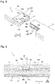
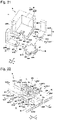
- the liquid vessel 1 includes a bottom portion 10 formed in a square shape, and a wall portion 15 formed in a square frame along an outer edge of the bottom portion 10.
- the wall portion 15 extends so as to rise from the outer edge (periphery) of the bottom portion 10 in a depth direction of the liquid vessel 1.
- the liquid vessel 1 is open on an opposite side of the bottom portion 10.
- the liquid vessel 1 holds a liquid L in an inner space I defined by the bottom portion 10 and the wall portion 15.
- the liquid vessel 1 is assembled from a plurality of first members 11, a second member 12 and a plurality of third members 13.
- the second member 12 is disposed in a central area of the bottom portion 10.
- the first members 11 are engaged with the second member 12.
- the third members 13 are engaged with the second member 12 and the first members 11.
- the peripheral edge of a main surface of each member is called an end portion. The engagement is made between facing end portions of the first members 11, the second member 12 and the third members 13.
- each first member 11 includes a first joint portion 1101 and a second joint portion 1102.
- the first joint portion 1101 forms a part of the bottom portion 10 of the liquid vessel 1 (see Fig. 1 ).
- the second joint portion 1102 extends from an outer end portion 1101a of the first joint portion 1101 so as to intersect the depth direction of the liquid vessel 1.
- the second joint portion forms a part of the wall portion 15 (see Fig. 1 ).
- each first member 11 has third recessed portions 117 on respective sides.
- the first joint portion 1101 of each first member 11 extends from the wall portion 15 of the liquid vessel 1 (see Fig. 1 ) to the second member 12.
- the first joint portion 1101 has a first engageable projecting portion 1110 formed on an end portion (hereinbelow, referred to as inner end portion) 1101b facing a central area of the liquid vessel 1.
- the first engageable projecting portion 1110 further includes a first projection 111 and a second recess 116.
- the first projection 111 has a pair of first projecting surfaces 111a and 111b.
- the second recess 116 has a pair of first recessed side surfaces 116a and 116b.
- the second member 12 is disposed in the central area of the bottom portion 15 (see Fig. 1 ).
- the first engageable projecting portion 1110 of each first joint portion 1101 is engaged with the second member 12.
- the second member 12 has a base 19 and a plurality of second engageable recessed portions 1210 formed on the periphery of the base 19.
- the second engageable recessed portions 1210 are circumferentially disposed at equal intervals so as to radially project from an outer periphery of the base 19 toward an external space O of the liquid vessel 1.
- each second engageable recessed portion 1210 includes a first recess 125 engageable with its corresponding first projection 111 and a pair of second projections 122 formed on the first recessed portion 125.
- Each first recessed portion 125 has a pair of first recessed surfaces 125a and 125b.
- Each second projection 122 has a pair of projecting side surfaces 122a and 122b.
- each first engageable projecting portion 1110 is engaged with the first recess 125 of its corresponding second engageable recessed portion 1210 to form a first engageable portion 101.
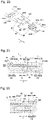
- Each first projection 111 is engaged with its corresponding first recessed portion 125 to form a first narrow space S1 defined by one 111a of its paired first projecting surfaces 111a and 111b, and one 125a of its corresponding paired first recessed surfaces 125a and 125b.
- a first narrow space S2 is formed, being defined by the other one 111b of each pair of first projecting surfaces 111a and 111b, and the other one 125b of the corresponding paired first recessed surfaces 125a and 125b.
- each first engageable portion 101 has a pair of the first narrow spaces S1 and S2.
- Each of the paired first narrow spaces S1 and S2 has a gap formed as a space that prevents the liquid L in the liquid vessel 1 from flowing out.
- the gap formed in each of the paired first narrow spaces S1 and S2 has a size that does not serve as a route allowing the liquid L to pass therethrough. This is also applicable to the narrow spaces described later.
- the gap is formed so as to extend in an engagement direction of its corresponding first member 11 and the second member 12 (directions indicated by an arrow A) and in an intersecting direction as viewed from a direction along a bottom surface (inner surface) 10a of the liquid vessel 1 (i.e. the depth direction of the liquid vessel 1).
- the gap of each pair of first narrow spaces S1 and S2 have a constant size. It is sufficient that the gap has a smaller size than a certain value.
- the gap may entirely or partly have a size of zero or have a size varying from position to position. This is also applicable to the gaps of the other narrow spaces described later.
- Each second recess 116 has its paired first recessed side surfaces 116a and 116b.
- Each second projecting portion 122 has its paired projecting side surfaces 122a and 122b.
- the second recess 116 of each first engageable projecting portion 1110 is engaged with the second projecting portions 122 of its corresponding second engageable recess 1210 to form a second engageable portion 102.
- Each second recess 116 is engaged with its corresponding second projecting portions 122 to form a second narrow space S3 defined by one 116a of its paired first recessed side surfaces 116a and 116b, and one 122a of its corresponding paired projecting side surfaces 122a and 122b.
- the other one 116b of each pair of first recessed side surfaces 116a and 116b is engaged with the other one 122b of its corresponding paired projecting side surfaces 122a and 122b to form a second narrow space S4.
- each second engageable portion 102 has its paired second narrow spaces S3 and S4.
- Each of the second narrow spaces S3 and S4 has a gap formed as a space that prevents the liquid L in the liquid vessel 1 from flowing out.
- the gap is formed so as to extend in the engagement direction of its corresponding first member 11 and the second member 12 (directions indicated by an arrow A) and in the direction along the bottom surface (inner surface) 10a of the liquid vessel 1.
- each first member 12 and the first joint portion 1101 of each first member 11 form a part of the bottom portion 10 of the liquid vessel 1 (see Fig. 1 ) in a state wherein each first projection 111 is engaged with its corresponding first recess 125 while each second projection 122 is engaged with its corresponding second recess 116 (see Fig. 7 as well).
- Each second joint portion 1102 extends in a direction intersecting its corresponding first joint portion 1101 (in other words, in the depth direction) such that each second joint portion 1102 forms a part of the wall portion 15 of the liquid vessel 1 (see Fig. 1 ).
- Each third member 13 has a third projection 133 engaged with the third recessed portion 117 of its corresponding first member 11 and a third recess 127 of the second member 12.
- Each third member 13 has a first flat area 1305 and a second flat area 1306. Further, each third member 13 has a third projection 133 engageable with the third recessed portion 117 of its corresponding first member 11 and the third recess 127 of the second member 12.
- the third recessed portion 117 of each first member 11 includes a pair of third recessed surfaces 117a and 117b.
- Each third projection 133 includes a pair of third projecting surfaces 133a and 133b.
- Each third projection 133 is engaged with the first joint portion 1101 of its corresponding first member 11 in a direction (directions indicated by an arrow B) intersecting the engagement direction of the first member 11 and the second member 12 (directions indicated by an arrow A).
- the third recess 127 of the second member 12 includes a pair of third recessed surfaces 127a and 127b.
- Each third projection 133 is engaged with the third recess 127 of the second member 12 in the direction (directions indicated by the arrow B) intersecting the engagement direction of the first member 11 and the second member 12 (directions indicated by an arrow A).
- the second member 12 and each third projection 133 form a third engageable portion 103 such that each first joint portion 1101 and the corresponding third projection 133 form a third engageable portion 103.
- Each third projection 133 is engaged with the third recessed portion 117 of its corresponding first member 11 (first joint portion 1101) to form a third narrow space S5 defined by the third projecting surface 133a of this third projection 133 and the third recessed surface 117a of this third recessed portion 117.
- a third narrow space S6 is formed, being defined by the third projecting surface 133b of this third projection 133 and the third recessed surface 117b of this third recessed portion 117.
- Each of the third narrow spaces S5 and S6 has a gap formed as a space that prevents the liquid L in the liquid vessel 1 from flowing out.
- the gap is formed so as to extend in a direction intersecting the engagement direction of its corresponding first member 11 and the second member 12 and in an intersecting direction (the depth direction of the liquid vessel 1) seen from the direction along the bottom surface 10a of the liquid vessel 1.
- Each third projection 133 is engaged with the third recess 127 of the second member 12 to form a third narrow space S5 defined by the third projecting surface 133a of this third projection 133 and the third recessed surface 127a of this third recess 127 as in the other portions of the third narrow space S5 formed by the other third projections 133 and the other first members 11.
- the third projecting surface 133b of a third projecting portion 133 and the third recessed surface 127b of its corresponding third recessed portion 127 form a third narrow space S6 as in the other portions of the third narrow spaces S6 formed by the other third projections 133 and the other first members 11.
- the first members 11 and the second member 12 are combined so as to be brought into contact with each other.
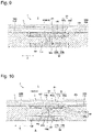
- a space P1 is formed between a leading edge 111c of each first projection 111 and a bottom 125c of each first recess 125 (see Fig. 6 ).
- each space P1 never communicates with the inner space I of the liquid vessel 1.
- a leading edge 133c of each third projecting portion 133 and a bottom 117c of its corresponding third recessed portion 117 are combined so as to be brought into contact with each other.
- a space P2 is formed between the combined leading edge and bottom.
- each space P2 never communicates with the external space O of the liquid vessel 1. This is because measures are taken such that the liquid L that has entered in the space P1 is prevented from flowing into the space P2.
- each second narrow space S3 is formed between its corresponding space P1 and its corresponding space P2, each second narrow space S3 is interposed between its corresponding first narrow space S1 and its corresponding third narrow space S5, and each first narrow space S1 and its corresponding third narrow space S5 communicate each other through its corresponding second narrow space S3.
- this space serves as a liquid route. Further, when displacement is made in other directions than the engagement direction, a liquid route is generated because there is no degree of freedom in the deformation among members.
- the provision of the third engageable portions blocks the liquid route in the other spaces to prevent a liquid from leaking outwardly. Further, the provision of the third engageable portions ensures a degree of freedom in the deformation among members with respect to the displacement of a first engageable portion and its corresponding second engageable portion in other directions than the engagement direction. Even when shifting is made in a direction toward or away from a third engageable portion to form a space, no liquid route is formed.
- the provision of such sets of three engageable portions according to the embodiment of the present invention ensures not only a degree of freedom in a single engagement direction but also a degree of freedom in engagement directions intersecting the single engagement direction. Further, even when engagement is shifted to generate a space, no liquid route is formed from the inner space of the liquid vessel to the external space of the liquid vessel so long as the engagement is maintained.
- the size of the spaces formed in the engageable portions may be defined by the lengths of the projections and the lengths of the recesses in the engageable portions in the engagement directions. From this point of view, it is sufficient to estimate how much shifting would occur in each engageable portion and to set the lengths of the projections and the lengths of the recesses in the engageable portions in the engagement directions to have greater lengths than the estimated shifting lengths so as to prevent disengagement.
- the liquid L is a molten metal of tin held in a liquid vessel 1 made of carbon
- the allowable gap of each narrow space will be specified below.
- the molten metal of tin has a depth set at 50 mm.
- the molten metal of tin has a surface tension of 0.5 N/m and a contact angle of 135 degrees to carbon and a density of 7,000 kg/m 3 . Based on these values, it is sufficient that the gap of each narrow space is not greater than 0.2 mm. Conversely, even when there is a narrow space having a gap of about 0.1 mm, the molten metal of tin is prevented from flowing out.
- the allowable gap of each narrow space will be specified below.
- the molten glass has a depth set at 50 mm.
- the molten glass has a surface tension of 0.3 N/m and a contact angle of 135 degrees to carbon and a density of 2,500 kg/m 3 . Based on these values, it is sufficient that the gap of each narrow space is not greater than 0.35 mm. Conversely, even when there is a narrow space having a gap of about 0.3 mm, the molten glass is prevented from flowing put.
- the allowable gap of each narrow space will be specified below.
- the water has a depth set at 50 mm.
- the water has a surface tension of 0.072 N/m and a contact angle of 135 degrees to the liquid vessel 1 having water repellency and a density of 1,000 kg/m 3 . Based on these values, it is sufficient that the gap of each narrow space is not greater than 0.2 mm.
- the liquid L is prevented from entering the respective narrow spaces by its surface tension.
- the provision of sets of a first narrow space S1, a second narrow space S3 and a third narrow space S5 can prevent the liquid from flowing out into their corresponding space P2.
- the inside of the liquid vessel 1 is made of the plurality of first members 11, the second member 12 and the plurality of third members 13. Thus, the liquid L can be prevented from flowing out from the inner space I of the liquid vessel to the external space O.
- the plurality of first members 11, the second member 12 and the plurality of third members 13 can be all engaged as illustrated in Figs. 2 and 3 to easily make up the liquid vessel 1 in a large size of prefabricated form. It is impossible to produce the structure of such a liquid vessel by using of the method of laying bricks.
- the liquid vessel 1 can be assembled in a large size so as to have the bottom portion 10 formed in a square shape in a planar view and the wall portion 15 formed in a square frame along the outer edge of the bottom portion 10.
- the liquid vessel 1 can be made up in a large size of prefabricated form by a simple structure that each first member 11 is merely provided with a first engageable projecting portion 1110 and a third recessed portion 117, the second member 12 is merely provided with the second engageable recessed portions 1210 and the third recessed portion 127, and each third member 13 is merely provided with a third projecting portion 133.
- the second member 12 is provided with the plurality of second engageable recessed portions 1210, and the first members 11 are engaged with the second engageable recessed portions 1210.
- the plurality of first members 11 are engaged with the single second member 12. The number of the parts required for assembling the liquid vessel 1 can be minimized to simplify the structure.
- the third members 13 are engaged with the first members 11 and the second member 12 to form the bottom portion 10 and the wall portion 15 of the liquid vessel 1 for example.
- the number of the parts required for assembling the liquid vessel 1 can be further minimized to simplify the structure.
- first joint portion 1101 of each first member 11 is provided with a first engageable projecting portion 1110
- second member 12 is provided with the second engageable recessed portions 1210
- the present invention is not limited to such a case.
- first joint portions 1101 of the first members 11 may be interchanged with the second engageable recessed portions 1210 of the second member 12 as another case.
- each set of three engageable portions is formed to have a first narrow space, a second narrow space and a third narrow space formed without a large gap being formed between engaged members.
- the liquid vessel 2 according to this modification is configured so as to have the same structure as the liquid vessel 1 according to the first embodiment except that the third members 13 are replaced with third members 23.
- Each third member 23 entirely has a uniform plate thickness T1.
- the plate thickness T1 is set to a thickness engageable with the third recessed portion 217 of a first member 21 to be engaged.
- each third member 23 has a plate thickness T1 equal to the thickness of each third projection 233.
- the entire plate thickness T1 of the third members 23 can be reduced to a thickness equal to the thickness of each third projection 233.
- the size of the plate thickness T1 of the third members 23 can be minimized to reduce the weight of the liquid vessel 2.
- the liquid vessel 3 includes a plurality of first members 31, a plurality of second members 32 and a plurality of third members 33. Further, the liquid vessel 3 includes a fourth member 34, a plurality of fifth members 35 and a plurality of sixth members 36.
- the fourth member 34 is disposed in a central area of a bottom portion of the liquid vessel 3 and is formed in a square shape in a planar view.
- Each fifth member 35 is engaged mainly between its adjacent first members 31 as in the respective members 11, 12 and 13 according to the first embodiment.
- the fifth members 35 are disposed at positions opposed to respective sides 34a to 34d of the fourth member 34.
- Each fifth member 35 is formed in an L-character shape in a side view and includes a portion 35b forming a part of the bottom portion of the liquid vessel 3 and a portion 35a forming a part of a wall portion of the liquid vessel 3.
- Each sixth member 36 is engaged between its adjacent fifth member 35 and the fourth member 34 opposing each other and between its adjacent pair of second members 32 as in the respective members 11, 12 and 13 according to the first embodiment.
- Each sixth member 36 forms a part of the bottom portion of the liquid vessel 3.
- the wall portion of the liquid vessel 3 is formed in a single layer and has a height of H1.
- the fourth member 34 is disposed in a central area of the bottom portion of the liquid vessel 3, and each fifth member 35 is engaged between its adjacent first members 31.
- the respective sides of the liquid vessel 3 can have longer lengths L1 and L2 than the sides of the liquid vessel 1 according to the first embodiment.
- the second modification allows the liquid vessel 3 to be produced in a larger size of prefabricated form than the liquid vessel 1.
- the liquid vessel 3 is not limited to this mode.
- the wall portion of the liquid vessel 3 may have a plurality of stacked layers and a larger height H1.
- the liquid vessel 4 includes a plurality of first members 41, a plurality of second members 42 and a plurality of third members 43.
- first member 41 the second joint portion 1102 of each first member 11 according to the first embodiment (see Fig. 3 ) is replaced with first joint portions 1101.
- each first member 41 is configured to have a pair of first joint portions 1101 formed in an L-character shape in a side view.
- Each third member 43 has an additional third projection (not shown) formed on sides corresponding to the opening sides of the third members 13 according to the first embodiment (see Fig. 3 ). In other words, each third member has a third projection extending from all peripheral sides.
- the plurality of first member 41, the plurality of second member 42 and the plurality of third members 43 are engaged as in the respective members 11, 12 and 13 according to the first embodiment. In this way, the plurality of first members 41, the plurality of second members 42 and the plurality of third members 43 are engaged to form the liquid vessel 4 in a fully-closed state with no opening.
- the liquid vessel 4 is provided as a prefabricated liquid vessel wherein the opening opposite to the bottom portion of the liquid vessel 1 according to the first embodiment is closed.
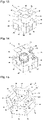
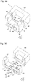
- the liquid vessel 5 has a bottom portion 50 formed in a hexagonal shape and a wall portion 55 formed in a hexagonal frame along an outer edge (peripheral sides) of the bottom portion 50.
- the liquid vessel 5 has a plurality of first members 51, a second member 52 and a plurality of third members 53.
- first member 51 the second joint portion 1102 of each first member 11 according to the first embodiment (see Fig. 3 ) is formed in a V-character shape in a planar view, and the remaining portions are formed in the same as those of each first member 11.
- the second member 52 is a member similar to the second member 12 according to the first embodiment (see Fig. 3 ).
- the second member 52 has six second recessed projecting portions 526 radially projecting from a base 59 at equal intervals.
- Each first member 51 has a first joint portion 5101 engaged with its corresponding second recessed projecting portion 526, being brought into contact with this second recessed projecting portion as in the first embodiment.
- Each third member 53 is disposed between its adjacent first members 51.
- an area corresponding to the first flat area 1305 of each third member 13 according to the first embodiment is formed in a triangular shape in a planar view, and the remaining portions are the same as those of each third member 13.
- Each third member 53 is engaged with its adjacent first member 51 and the second member 52 as in the first embodiment.
- the liquid vessel 6 has a bottom portion 60 formed in an octagonal shape and a wall portion 65 formed in an octagonal frame along an outer edge (peripheral sides) of the bottom portion 60.
- the liquid vessel 6 includes a plurality of first members 61, a second member 62, a plurality of third members 63 and a plurality of fourth members 64.
- each first member 61 a portion corresponding to the second joint portion 1102 of each first member 11 according to the first embodiment (see Fig. 3 ) is formed in a V-character shape in a planar view, and the remaining portions are formed in similar to those of each first portion 11.
- the second member 62 is disposed a central area of the bottom portion 60 of the liquid vessel 6 so as to be formed in an octagonal shape in a planar view.
- the plurality of fourth members 64 are engaged with peripheral sides of the second member 62.
- Each first member 61 is engaged with its corresponding fourth member 64, being brought into contact with this fourth member.
- Each third member 63 is engaged between its adjacent first members 61.
- the first members 61, the second member 62, the third members 63 and the fourth members 64 are engaged together as in the first members 11, the second member 12 and the third members 13 according to the first member to produce a prefabricated liquid vessel.
- the liquid vessel 7 has a bottom portion 70 formed in a circular shape and a wall portion 75 formed in a cylindrical shape along an outer edge (peripheral side) of the bottom portion 70.
- the liquid vessel 7 includes a plurality of first members 71, a second member 72 and third members 73.
- each first member 71 the second joint portion 1102 of each first member 11 according to the first embodiment (see Fig. 3 ) is formed in a curved shape in a planar view.
- the second member 72 is disposed in an central area of the bottom portion 70 of the liquid vessel 7.
- the first members 71 are engaged with the second member 72, being brought into contact with the second member.
- Each third member 73 is engaged between its adjacent first members 71.
- the second flat area 1306 of each third member 13 according to the first embodiment is formed in an arc-shape in a planar view.
- the first members 71, the second member 72 and the third members 73 are engaged together as in the first members 11, the second member 12 and the third member 13 according to the first embodiment to produce a prefabricated liquid vessel.
- each of the liquid vessels 1, 2, 3, 4, 5, 6 and 7 allows the bottom portion to be formed in a polygonal shape and the wall portion to be formed in a polygonal frame along the out edge (peripheral sides) of the bottom portion.
- the shape of the liquid vessel can be selected according to applications of the liquid vessel to expand the applications of the liquid vessel.
- liquid vessels 8 and 9 according to a second embodiment and a third embodiment will be described in reference to Figs. 19 to 27 and Figs. 28 to 34 .
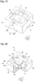
- the liquid vessel 8 As illustrated in Figs. 19 and 20 , the liquid vessel 8 according to this embodiment is made up by a bottom portion 80 formed in a square shape and a wall portion 85 formed in a square frame along an outer edge (peripheral sides) of the bottom portion 80. Further, the liquid vessel 8 is opened on an opposite side of the bottom portion 80. The liquid vessel 8 is configured so as to hold a liquid L in an inner space I defined by the bottom portion 80 and the wall portion 85.
- the liquid vessel 8 is assembled from a plurality of first members 81, a second member 82 and a plurality of third members 83.
- the second member 82 is disposed in a central area of the bottom portion 80.
- the plurality of first members 81 are engaged with the second member 82.
- Each third member 83 is engaged with its adjacent first members 81 and the second member 82.
- each first member 81 includes a first joint portion 8101 and a second joint portion 8102.
- the first joint portion 8101 forms a part of the bottom 80 of the liquid vessel 8 (see Fig. 19 ).
- the second joint portion 8102 extends from an outer end portion 8101a of the first joint portion 8101 to a depth direction of the liquid vessel 8.
- the second joint portion 8102 of each first member forms a part of the wall portion 85.
- each first joint portion 8101 includes a first inner joint surface 8101c, a first outer joint surface 8101d and a pair of first side joint surfaces 8101e.
- Each first inner joint surface 8101c is disposed on a side of the inner space I of the liquid vessel 8.
- Each first outer joint surface 8101d is disposed on a side of an external space O of the liquid vessel 8.
- One of paired first side joint surfaces 8101e is disposed to connect between one of both sides of the first inner joint surface 8101c and one of both sides of the first outer joint surface 8101d.
- the other one of the paired first side point surfaces 8101e is disposed to connect between the other side of the first inner joint surface 8101c and the other side of the first outer joint surface 8101d.
- Each first joint portion 8101 is formed in a rectangular shape in section by its first inner joint surface 8101c, first outer joint surface 8101d and paired first side joint surfaces 8101e.
- Each joint portion 8101 extends from the wall portion 85 of the liquid vessel 8 (see Fig. 19 ) to the second member 82.
- Each first joint portion 8101 includes a first engageable projecting portion 8110 formed on an end portion (hereinbelow, referred to as inner end portion) 8101b close to a central side of the liquid vessel 8.
- Each first engageable projecting portion 8110 is provided with a first projection 811 and a second projection 812.
- Each first projection 811 is formed in a rectangular shape in section and projects toward a central area side of the liquid vessel 8 in a direction along a bottom surface (inner surface) 80a of the liquid vessel 8.
- Each second projection 812 is formed on a side of a bottom surface 80a of the liquid vessel 8 with respect to its corresponding first projection 811. Each second projection 812 projects toward the central area side of the liquid vessel 8 in the direction along the bottom surface 80a of the liquid vessel 8.
- each first joint portion 8101 has a second joint portion 8102 formed on an outer end portion (opposite end portion) 8101a of its corresponding first engageable projecting portion 8110.
- Each second joint portion 8102 extends in a direction intersecting its corresponding first joint portion 8101 (in other words, a depth direction of the liquid vessel 8).
- the second joint portions 8102 are formed in a rectangular shape in section as in the first joint portions 8101.
- the second member 82 is disposed at a central portion of the bottom portion 80 (see Fig. 19 ).
- the first engageable projecting portion 8110 of each first joint portion 8101 is engaged with the second member 82.
- the second member 82 includes a base 89 forming the central portion and a plurality of second engageable recessed portions 8210 formed the periphery of the base 89.
- the second engageable recessed portions 8210 are disposed at four positions on the outer periphery of the base 89.
- the second engageable recessed portions 8210 are circumferentially disposed at equal intervals so as to radially project from the outer periphery of the base 89 toward an external space O of the liquid vessel 8.
- Each second engageable recessed portion 8210 includes a first recess 825 engageable with its corresponding first projection 811 and a second recess 826 formed at the first recess 825.
- each second engageable portion 8210 includes a first inner engageable surface 8210a, a first outer engageable surface 8210b and a pair of first engageable side surfaces 8210c.
- Each first inner engageable surface 8210a is disposed on a side of the inner space I of the liquid vessel 8.
- Each first outer engageable surface 8210b is disposed on a side of the external space O of the liquid vessel 8.
- One of paired first engageable side surfaces 8210c is disposed to connect between one side of its corresponding first inner engageable surface 8210a and one side of its corresponding outer engageable surface 8210b.
- the other one of paired first engageable side surfaces 8210c is disposed to connect between the other side of its corresponding first inner engageable surface 8210a and the other side of its corresponding first outer engageable surface 8210b.
- Each second engageable recessed portion 8210 has an outer shape formed in a rectangular shape in section by its corresponding first inner engageable surface 8210a, first outer engageable surface 8210b and paired first engageable side surfaces 8210c.
- Each first recess 825 is open so as to be engageable with its corresponding first projection 811.
- Each second recess 826 is formed in a part of its corresponding second engageable recessed portion 8210 close to the bottom surface 80a of the liquid vessel 8 and is formed in a groove shape so as to be engageable with its corresponding second projection 812.
- Each first projection 811 is engaged with its corresponding first recess 825 to form a first engageable portion 801.
- Each second projection 812 is engaged with its corresponding second recess 826 to form a second engageable portion 802.
- the first projections 811 are engaged with the first recesses 825, and the second projections 812 are engaged with the second recesses 826, causing the first joint portions 8101 to radially extend from the second member 82.
- first inner joint surface 8101c of each first joint portion 8101 and the first inner engageable surface 8210a of its corresponding second engageable recessed portion 8210 are disposed to be flush with each other.
- the first outer joint surface 8101d of each first joint portion 8101 and the first outer engageable surface 8210b of its corresponding second engageable recessed portion 8210 are disposed to be flush with each other.
- Each first projecting portion 811 includes a pair of first projecting surfaces 811a and 811b.
- Each first recess 825 includes a pair of first recessed surfaces 825a and 825b.
- Each first projecting portion 811 is engaged with its corresponding first recess 825 to form a first narrow space S7 defined by one 811a of its paired first projecting surfaces 811a and 811b and one 825a of its corresponding paired first recessed surfaces 825a and 825b.
- the other one 811b of the paired first projecting surfaces 811a and 811b and its corresponding paired first recessed surfaces 825a and 825b form a first narrow space S8.
- each first engageable portion 801 includes a pair of first narrow spaces S7 and S8.
- Each of paired first narrow spaces S7 and S8 has a gap formed as a space that prevents the liquid L in the liquid vessel 8 from flowing out.
- each of the first narrow spaces S7 and S8 is formed to have such a gap that the liquid L is prevented from entering each of the first narrow spaces S7 and S8 by surface tension.
- the gap is formed so as to extend in an engagement direction of the first members 81 and the second member 82 (directions indicated by an arrow A) and in an intersecting direction as viewed from a direction along the bottom surface (inner surface) 80a of the liquid vessel 8 (i.e. the depth direction of the liquid vessel 8).
- each second projecting portion 812 has a pair of second projecting side surfaces 812a and 812b.
- Each second recess 826 includes a pair of second recessed side surfaces 826a and 826b.
- Each second projecting portion 812 is engaged with its corresponding second recess 826 to form a second narrow space S9 defined by one 812a of its paired second projecting side surfaces 812a and 812b and one 826a of its corresponding paired second recessed side surfaces 826a and 826b.
- the other one 812b of paired second projecting side surfaces 812a and 812b and the other one 826b of its corresponding paired second recessed side surfaces 826a and 826b form a second narrow space S10.
- each second engageable portion 802 includes a pair of second narrow spaces S9 and S10.
- Each of the paired second narrow spaces S9 and S10 has a gap formed as a space that prevents the liquid L in the liquid vessel 8 from flowing out.
- each of the paired second narrow spaces S9 and S10 is formed so as to have a gap sized to prevent the liquid L from entering their corresponding first narrow spaces S7, S8 by surface tension.
- the gap is formed so as to extend in the engagement direction of the first members 81 and the second member 82 and in the direction along the bottom surface (inner surface) 80a of the liquid vessel 8.
- each third member 83 includes a first flat area 8305 and a second flat area 8306.
- Each first flat area 8305 is formed in a rectangular shape in a planar view and forms a part of the bottom portion 80 of the liquid vessel 8 (see Fig. 19 ).
- Each second flat area 8306 is bent in an L-character shape along an outer edge (peripheral side) of its corresponding first flat area 8305 in a planar view and forms a part of the wall portion 85 of the liquid vessel 8 (see Fig. 9 ).
- each third member 83 includes third recessed portions 833 engageable with its adjacent first members 81 and its adjacent second member 82.
- Each third recessed portion 833 has a third bottom recessed portion 837H formed at the first flat area 8305 and a third wall recessed portion 837V formed at the second flat area 8306.
- Each third bottom recessed portion 837H is formed in a recessed shape in section so as to be engageable with the first joint portion 8101 of its adjacent first member 81 and the second member 82.
- Each third wall recessed portion 837V is formed in recessed shape in section so as to be engageable with the second joint portion 8102 of its adjacent first member 81.
- each third member 83 is engaged with third projecting portions 813 and 823 formed at lateral positions of its adjacent first members 81 and the second member 82, being brought into contact with these third projecting portions in a direction (directions indicated by an arrow B) intersecting the engagement direction of this adjacent first member 81 and the second member 82 (directions indicated by an arrow A).
- Each third member 83 is engaged with its adjacent first member 81 in such a state that the plurality of first members 81 are engaged with the second member 82.
- each third bottom recessed portion 837H is formed in a recessed shape in section and includes a third inner bottom recessed surface 837Ha and a third outer bottom recessed surface 837Hb.
- the third inner bottom recessed surfaces 837Ha and the third outer bottom recessed surfaces 837Hb are formed along the bottom surface 80a of the liquid vessel 8.
- Each third bottom recessed portion H is engaged with the first joint portion 8101 of its adjacent first member 81 in a direction (directions indicated by an arrow B) intersecting an engagement direction of its adjacent first member 81 and the second member 82 (directions indicated by an arrow A).
- Each first joint portion 8101 and its corresponding third bottom recessed portion 837H form a third engageable portion 803.
- each third bottom recessed portion 837H is engaged with the second member 82 in a direction (directions indicated by an arrow B) intersecting the engagement direction of its adjacent first member 81 and the second member 82 (directions indicated by the arrow A).
- the second member 82 and each third bottom recessed portion 837H form a third engageable portion 803.
- Each third bottom recessed portion 837H is engaged with the first joint portion 8101 of its adjacent first member 81 to form a third narrow space S11 defined by its third inner bottom recessed surface 837Ha and the first inner joint surface 8101c of this first joint portion 8101.
- Each third outer bottom recessed surface 837Hb and the first outer joint surface 8101d of its corresponding first joint portion 8101 form a third narrow space S12.
- each third bottom recessed portion 837H is engaged with the second member 82 to form a third narrow space S11 defined by its third inner bottom recessed surface 837Ha and the first inner engageable surface 8210a of its corresponding first joint portion 8101.
- Each third outer bottom recessed surface 837Hb and the first outer engageable surface 8210b of its corresponding first joint portion 8101 form a third narrow space S12.
- the gap is formed as a space that prevents the liquid L in the liquid vessel 8 from flowing out.
- the gap is formed so as to extend in a direction intersecting the engagement direction of the first members 81 and the second member 82 and in an intersecting direction as viewed from the direction along the bottom surface 80a of the liquid vessel 8 (the depth direction of the liquid vessel 8).
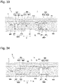
- each third recessed all portion 837V of each second flat area 8306 is engaged with the second joint portion 3102 of its adjacent first member 81 to form a third narrow space S13 and a third narrow space S14.
- Each third narrow space S13 is continuous to its corresponding third narrow space S11 (see Fig. 24 ).
- Each third narrow space S14 is continuous to its corresponding third narrow space S12 (see Fig. 24 ).
- Each of the third narrow spaces S13 and S14 has a gap formed as a space that prevents the liquid L in the liquid vessel 8 from flowing out.
- each of the third narrow spaces S13 and S14 has a gap to prevent the liquid L from entering its corresponding narrow spaces S7 and S8 based on the relationship between the surface tension and the contact angle of the liquid.
- the first projecting surface 811a of each first projecting portion 811 and the first recessed surface 825a of its corresponding first recess 825 form a first narrow space S7 on a side of the bottom surface 80a of the liquid vessel 8.
- the second projecting side surface 812a of each second projecting portion 812 and the second recessed side surface 826a of its corresponding second recess 826 form a second narrow space S9 on the side of the bottom surface 80a of the liquid vessel 8.
- each second engageable recessed portion 8210 and the third inner bottom recessed surface 837Ha of its corresponding third bottom recessed portion 837H form a third narrow space S11 on the side of the bottom surface 80a of the liquid vessel 8.
- Each second narrow space S9 is interposed between its adjacent first narrow space S7 on the side of the bottom surface 80a and its adjacent third narrow space S11 on the side of the bottom surface 80a, and each first narrow space S7 on the side of the bottom surface 80a is continuous to its adjacent third narrow space S11 on the side of the bottom surface 80a through their adjacent second narrow space S9.
- Each first member 81 and the second member 82 are brought into contact with each other so as to form a space P3 and a space P4 at their first engageable portion 801 and their second engageable portion 802 when the liquid vessel is subjected, for example, to deformation caused by an earthquake or to an installation error.
- the first flat area 8305 of one of adjacent third members 83 and the first flat area 8305 of the other one of these adjacent third members 83 are brought into contact with each other so as to form a space P5a between these adjacent third members 83 brought into contact with each other, when the liquid vessel is subjected, for example, to deformation caused by an earthquake or to an installation error.
- each first member 81 and its adjacent third member 83 are brought into contact with each other so as to form a space P5b when the liquid vessel is subjected, for example, to deformation caused by an earthquake or to an installation error.
- each space P4 never communicates with the external space O of the liquid vessel 8.
- the space P3 between each second projecting portion 812 and its corresponding second recess 826 never communicates with the space P5a between the first flat areas 8305 and 8305 on both sides of its corresponding first joint portion 8101. This is because measures are taken such that the liquid L that has entered in each space P3 is prevented from flowing into its corresponding space P4.
- sets of a first narrow space S7, a second space S9 and a third space S11 are provided.
- sets of a first narrow space S7, a second space S9 and a third space S11 avoid that the liquid L that flows into the spaces P3 from their corresponding spaces P5a flows into the spaces P4.
- the plurality of first members 81, the second member 82 and the plurality of third members 83 can be all engaged as illustrated in Figs. 20 and 21 to easily make up the liquid vessel 8 in a large size of prefabricated form.
- the liquid vessel 8 can be assembled in a large size so as to have the bottom portion 80 formed in a square shape in a planar view and the wall portion 85 formed in a square frame along the bottom portion 80.
- the liquid vessel 8 can be made up in a large size of prefabricated form by a simple structure that each first member 81 is merely provided with a first projecting portion 811 and a second projecting portion 812, the second member 82 is merely provided with the first recesses 825 and the second recesses 826, and each third member 13 is merely provided with a third recessed portion 833.
- the second member 82 is provided with a plurality of second engageable recessed portions 8210, and the first members 11 are engaged with the second engageable recessed portions 8210.
- the plurality of first members 81 are engaged with the single second member 82.
- the number of the parts required for assembling the liquid vessel 8 can be minimized to simplify the structure.
- the third members 83 are engaged with the first members 81 and the second member 82 to form the bottom portion 80 and the wall portion 85 of the liquid vessel 8 for example.
- the number of the parts required for assembling the liquid vessel 8 can be further minimized to simplify the structure.
- each first joint portion 8101 of each first member 81 is provided with a first engageable projecting portion 8110, and the second member 82 is provided with the second engageable recessed portions 8210
- the present invention is not limited to such a case.
- each first joint portion 8101 may be provided with a second engageable recessed portion 8210, and the second member 82 may be provided with first engageable projecting portions 8110.
- the liquid vessel 9 includes a bottom portion 90 formed in a square shape, and a wall portion 95 formed in a square frame along an outer edge (peripheral sides) of the bottom portion 90.
- the liquid vessel 9 is open on an opposite side of the bottom portion 90.
- the liquid vessel 9 is configured to hold a liquid L in an inner space I defined by the bottom portion 90 and the wall portion 95.
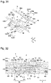
- the liquid vessel 9 is assembled from a first member 91, a second member 92 and a pair of third members 93A and 93B.
- the first member 91 is disposed at a central position of the liquid vessel 9 in the directions indicated by the arrow B and on one side in the directions indicated by the arrow A.
- the second member 92 is disposed at a central position of the liquid vessel 9 in the directions indicated by the arrow B and on the other side in the directions indicated by the arrow A.
- Each of the first member 91 and the second member 92 is formed in an L-character shape in a side view.
- the first member 91 has a leading edge portion 911a engaged with a leading edge portion 922a of the second member 92.
- the first member 91 has a third recessed portion 917 formed at one of lateral sides while the second member 92 has a third recessed portion 927 formed at one of lateral sides.
- the first member 91 has a third projecting portion 913 formed on the other lateral side while the second member 92 has a third projecting portion 923 formed at the other lateral side.
- the third member 93A has third projecting portions 931 engaged with the third recessed portions 917 and 927 to form one 903A of third engageable portions.
- the third member 93B has a third recessed portion 937 engaged with the third projecting portions 913 and 923 to form the other 903B of the third engageable portions.
- the first member 91 has a first projecting portion 911 engaged with a first recessed portion 925 of the second member 92 to form a first engageable portion 901.
- the first projecting portion 911 has projecting side surfaces, one 911a of which forms a fourth narrow space S15 along with its corresponding one 925a of recessed side surfaces of the first recessed portion 925.
- the other projecting side surface 911b of the first projecting portion 911 forms a fourth narrow space S16 along with the other recessed side surface 925b of the first recessed portion 925.
- Each of the fourth narrow spaces S15 and S16 has a gap formed as a space that prevents the liquid L in the liquid vessel 9 from flowing out.
- the first member 91 has a second projecting portion 912 engaged with a second recess 926 of the second member 92 to form a second engageable portion 902.
- the second projecting portion 912 has a projecting side surface 912a, which forms a second narrow space S17 along with a recessed side surface 926a of the second recess 926.
- the second narrow space S17 has a gap formed as a space that prevents the liquid L in the liquid vessel 9 from flowing out.
- the third member 93B has a third recessed portion 937, which has a recessed surface 937a to form a third narrow space S18 along with a projecting surface 922 on the other side of the second member 92.
- the third narrow space S18 has a gap formed as a space that prevents the liquid L in the liquid vessel 9 from flowing out.
- first member 91 has a fourth projecting portion 914 engaged with a fourth recessed portion 928 of the second member 92 to form a fourth engageable portion 904.
- the fourth projecting portion 928 has a recessed surface 928a, which forms a first narrow space S19 along with a projecting surface 914a of the fourth projecting portion 914.
- the first narrow space S19 has a gap formed as a space that prevents the liquid L in the liquid vessel 9 from flowing out.
- the second narrow space S17 is interposed between the first narrow space S19 and the third narrow space S18, and the first narrow space S19 is continuous to the third narrow space S18 through the second narrow space S17.
- the liquid L that flows into a space P6 is prevented from flowing into a space P8 through a space P8 by the first narrow space S19, the second narrow space S17 and the third narrow space S18.
- the third projecting portion 931 is engaged with the third recessed portions 917 and 927.
- a recessed surface 917a of the third recessed portion 917 and a recessed surface 927a of the third recessed portion 927 form one of third narrow spaces S20.
- the one of the third narrow spaces S20 has a gap formed as a space that prevents the liquid L in the liquid vessel 9 from flowing out.
- the liquid L that flows into a space P9 is prevented from flowing into a space P10 by the third narrow portion S20.
- the third recessed portion 937 is engaged with the third projecting portion 913 of the first member 91 and the third projecting portion 923 of the second member 92.
- a recessed surface 937a of the third recessed portion 937, a projecting surface 913a of the third projecting portion 913 and a projecting surface 923a of the third projecting portion 923 form other third narrow space S21.
- the other third narrow space S21 has a gap formed as a space that prevents the liquid L in the liquid vessel 9 from flowing out.
- the liquid vessel 9 has an inner side defined by the first member 91, the second member 92 and the paired third members 93A and 93B.
- the liquid L that flows into a space P11 is prevented from flowing into a space P12 by the other third narrow portion S21.
- first member 91, the second member 92 and the paired third members 93A and 93B can be all engaged as illustrated in Figs. 28 to 34 to easily make up the liquid vessel 9 in a large size of prefabricated form.
- the liquid vessel 9 can be assembled in a large size so as to have the bottom portion 90 formed in a square shape in a planar view and the wall portion 95 formed in a square frame along the bottom portion 90.
- the liquid vessel according to the present invention is applicable to a vessel for holding various kinds of liquids in a wide range of fields.
- the liquid vessel is usable as a molten metal bath for glass product production, which holds a liquid, such as molten metal for producing glass products, such as glass plates, by a float process, for example, disclosed in WO2012/060197A .
- molten metal bath used in a float process for example, molten metal, specifically molten tin, is held as the liquid L.
- the liquid vessel is applicable to a bath for holding molten glass for producing glass products.
- the liquid vessel is applicable to a refiner for removing bubbles in molten glass after melding glass materials, a canal for forming molten glass by a down-draw process, or a forming apparatus called sword.
- the liquid vessel according to the present invention may be used in the method for producing glass products such that a molten metal bath, a canal, a sword or the like that has been used in conventional glass production equipment is replaced by the vessel structure according to the present invention.
- the materials for forming the liquid vessel according to the present invention may be different, depending on the kinds of held liquids, and materials which are not eroded by a held liquid is normally used. For example, stainless steel is used. For example, as the materials required to be refractory, carbon, a boron nitride or the like may be used.
Landscapes
- Engineering & Computer Science (AREA)
- Mechanical Engineering (AREA)
- Chemical & Material Sciences (AREA)
- Materials Engineering (AREA)
- Organic Chemistry (AREA)
- Manufacturing & Machinery (AREA)
- Details Of Rigid Or Semi-Rigid Containers (AREA)
- Rigid Containers With Two Or More Constituent Elements (AREA)
- Ink Jet (AREA)
- Containers And Packaging Bodies Having A Special Means To Remove Contents (AREA)
- Re-Forming, After-Treatment, Cutting And Transporting Of Glass Products (AREA)
- Glass Compositions (AREA)
- Table Devices Or Equipment (AREA)
- Thermally Insulated Containers For Foods (AREA)
- Devices For Use In Laboratory Experiments (AREA)
Applications Claiming Priority (3)
| Application Number | Priority Date | Filing Date | Title |
|---|---|---|---|
| JP2017150857 | 2017-08-03 | ||
| PCT/JP2018/028485 WO2019026852A1 (ja) | 2017-08-03 | 2018-07-30 | 液体を収容する容器 |
| EP18840611.0A EP3663234B1 (de) | 2017-08-03 | 2018-07-30 | Behälter zur aufnahme einer flüssigkeit und verfahren damit |
Related Parent Applications (2)
| Application Number | Title | Priority Date | Filing Date |
|---|---|---|---|
| EP18840611.0A Division EP3663234B1 (de) | 2017-08-03 | 2018-07-30 | Behälter zur aufnahme einer flüssigkeit und verfahren damit |
| EP18840611.0A Division-Into EP3663234B1 (de) | 2017-08-03 | 2018-07-30 | Behälter zur aufnahme einer flüssigkeit und verfahren damit |
Publications (3)
| Publication Number | Publication Date |
|---|---|
| EP4043364A2 true EP4043364A2 (de) | 2022-08-17 |
| EP4043364A3 EP4043364A3 (de) | 2022-10-19 |
| EP4043364B1 EP4043364B1 (de) | 2024-09-04 |
Family
ID=65232560
Family Applications (2)
| Application Number | Title | Priority Date | Filing Date |
|---|---|---|---|
| EP22160688.2A Active EP4043364B1 (de) | 2017-08-03 | 2018-07-30 | Behälter zur aufnahme einer flüssigkeit und verfahren damit |
| EP18840611.0A Active EP3663234B1 (de) | 2017-08-03 | 2018-07-30 | Behälter zur aufnahme einer flüssigkeit und verfahren damit |
Family Applications After (1)
| Application Number | Title | Priority Date | Filing Date |
|---|---|---|---|
| EP18840611.0A Active EP3663234B1 (de) | 2017-08-03 | 2018-07-30 | Behälter zur aufnahme einer flüssigkeit und verfahren damit |
Country Status (6)
| Country | Link |
|---|---|
| US (1) | US11702243B2 (de) |
| EP (2) | EP4043364B1 (de) |
| JP (2) | JP6888680B2 (de) |
| CN (2) | CN113734642B (de) |
| TW (2) | TWI772481B (de) |
| WO (1) | WO2019026852A1 (de) |
Families Citing this family (1)
| Publication number | Priority date | Publication date | Assignee | Title |
|---|---|---|---|---|
| US11851357B2 (en) * | 2021-09-09 | 2023-12-26 | James William Masten, JR. | Method for forming shaped glass |
Citations (3)
| Publication number | Priority date | Publication date | Assignee | Title |
|---|---|---|---|---|
| JP2010215239A (ja) | 2009-03-13 | 2010-09-30 | Rihei Suzuki | 組立式容器 |
| WO2012060197A1 (ja) | 2010-11-04 | 2012-05-10 | 旭硝子株式会社 | フロート板ガラスの製造方法およびフロート板ガラスの製造装置 |
| JP2017150857A (ja) | 2016-02-22 | 2017-08-31 | 株式会社キーエンス | 安全スキャナ |
Family Cites Families (47)
| Publication number | Priority date | Publication date | Assignee | Title |
|---|---|---|---|---|
| FR1270366A (fr) * | 1960-10-14 | 1961-08-25 | Ouvrage préfabriqué et éléments pour sa construction | |
| FR1357788A (fr) * | 1963-02-28 | 1964-04-10 | Anciens Etablissements Sadon | Réservoir de grande capacité pour produits corrosifs |
| JPS493797Y1 (de) * | 1969-08-29 | 1974-01-30 | ||
| JPS519941A (en) * | 1974-07-15 | 1976-01-27 | Toshiba Machine Co Ltd | Shihenni ototsunoarumenzai |
| US4244486A (en) * | 1979-05-11 | 1981-01-13 | Ewald Jr Herbert J | Tank |
| JPS58143319U (ja) * | 1982-03-19 | 1983-09-27 | 株式会社昭和丸筒 | 組立式外装体 |
| CA1246890A (en) * | 1988-03-10 | 1988-12-20 | Paul J. Kruger | Composite panel, wall assembly and components therefor |
| US5155872A (en) * | 1990-10-25 | 1992-10-20 | Aymes Doniel G | Swimming pool with interlocking wall panels and liner-receiving top rail |
| US6902061B1 (en) * | 2000-09-29 | 2005-06-07 | Paul Elstone | Collapsible liquid box |
| JP2002314221A (ja) * | 2001-04-16 | 2002-10-25 | Tokyo Kakoki Kk | 処理室およびその製造方法 |
| DE10133471B4 (de) * | 2001-07-10 | 2004-09-30 | Schott Glas | Wanne zur Aufnahme eines Schmelzbades aus Glas oder Glaskeramik |
| FR2830850B1 (fr) * | 2001-10-15 | 2003-12-26 | Glaverbel | Cale pour cavalier espaceur |
| CN1462713A (zh) * | 2002-05-28 | 2003-12-24 | 岐阜塑料工业株式会社 | 组装容器 |
| JP2004268989A (ja) * | 2003-03-10 | 2004-09-30 | Fujikowa Industry Co Ltd | 折り畳み搬送容器 |
| WO2005007519A2 (en) * | 2003-07-07 | 2005-01-27 | Derifield Rodney M | Insulated shipping containers |
| DE10362131A1 (de) * | 2003-08-01 | 2006-06-14 | Gea Buck Valve Gmbh | Kupplungsverschlüsse sowie Andockeinrichtungen enthaltend diese Kupplungsverschlüsse |
| WO2005035394A1 (ja) * | 2003-10-09 | 2005-04-21 | Asahi Glass Company, Limited | ガラス板梱包箱、梱包方法及び開梱方法 |
| US7360784B2 (en) * | 2004-02-13 | 2008-04-22 | Ultimate Survival Technologies, Llc | Multifunctional mobile storage and delivery system |
| JP2005329994A (ja) | 2004-05-21 | 2005-12-02 | Daiwa Kasei Ind Co Ltd | 組付式収容箱 |
| NO20042678D0 (no) * | 2004-06-25 | 2004-06-25 | Det Norske Veritas As | Tank for storage of fluids at low temperatures, support means for a tank, sandwich structure for use in a tank and method for manufacturing a tank |
| KR100625119B1 (ko) * | 2005-03-29 | 2006-09-20 | 주식회사 시온테크닉스 | 조립식 원형 물탱크 |
| US7708160B2 (en) * | 2006-01-10 | 2010-05-04 | United States Postal Service | Collapsible container |
| US7703632B2 (en) * | 2006-08-04 | 2010-04-27 | Kochanowski George E | Stackable and collapsible container |
| JP3128241U (ja) | 2006-10-20 | 2006-12-28 | 西武造園株式会社 | 組立式構造体 |
| US7896184B2 (en) * | 2007-11-26 | 2011-03-01 | Rehrig Pacific Company | Crate with collapsible wall |
| US20090302046A1 (en) * | 2008-06-10 | 2009-12-10 | You Crate Llc | Collapsible Containers |
| CN102112334B (zh) * | 2008-07-31 | 2013-06-26 | F3&I2有限责任公司 | 用于箱体的模块化嵌板 |
| DE102009033502B4 (de) * | 2009-07-15 | 2016-03-03 | Schott Ag | Verfahren und Vorrichtung zur Herstellung von Glasprodukten aus einer Glasschmelze |
| AU2009227869A1 (en) * | 2009-10-19 | 2011-05-12 | K. Hartwall Oy Ab | Collapsible Crate for Transportation and Display of Pieces, and Method for Supplying and Merchandising Products |
| MX2011005654A (es) * | 2010-05-27 | 2011-11-28 | Rehring Pacific Company | Contenedor plegable de altura dual. |
| JP5591640B2 (ja) * | 2010-09-17 | 2014-09-17 | AzエレクトロニックマテリアルズIp株式会社 | 液体用コンテナとその組み立て方法 |
| KR20140007356A (ko) * | 2011-01-20 | 2014-01-17 | 아사히 가라스 가부시키가이샤 | 유리 롤, 유리 롤 제조 장치 및 유리 롤 제조 방법 |
| JP5049411B1 (ja) | 2011-06-12 | 2012-10-17 | 株式会社テクノミズホ | 組立式植栽用容器の組立てセット及び組立式植栽用容器 |
| JP5145485B1 (ja) * | 2011-08-10 | 2013-02-20 | 東京機材工業株式会社 | 側壁ユニット及びその製造方法、並びに該側壁ユニットを備えた液体貯蔵タンク |
| CN202246389U (zh) * | 2011-08-23 | 2012-05-30 | 信义节能玻璃(芜湖)有限公司 | 锡槽及其顶盖结构 |
| WO2014112485A1 (ja) * | 2013-01-17 | 2014-07-24 | 旭硝子株式会社 | 成形体の製造方法及びガラス成形体の製造方法 |
| WO2014125878A1 (ja) * | 2013-02-13 | 2014-08-21 | 株式会社カネカ | 定温保管輸送容器及び輸送方法 |
| US9555959B1 (en) * | 2013-08-31 | 2017-01-31 | Dustin Ziegs | Modular fluid storage tank |
| CN203512373U (zh) * | 2013-09-18 | 2014-04-02 | 京东方科技集团股份有限公司 | 包装箱 |
| FI20145453A7 (fi) * | 2014-05-20 | 2015-11-21 | Outotec Finland Oy | Nestesäiliö |
| US20150353232A1 (en) | 2014-06-06 | 2015-12-10 | Edward Kandel | Size-adjustable receptacle |
| CN105197344A (zh) * | 2014-06-25 | 2015-12-30 | 艾尔戴克斯国际公司 | 承载结构 |
| JP3198009U (ja) * | 2015-03-31 | 2015-06-11 | 積水化成品工業株式会社 | 梱包材及び梱包体 |
| CN105691821B (zh) * | 2016-03-29 | 2017-12-05 | 福建省农业科学院生物技术研究所 | 拼接结构和拼接箱体 |
| CN106005777A (zh) * | 2016-06-28 | 2016-10-12 | 天津天纺高新物流有限公司 | 一种可变换容积量的拼接物流箱 |
| CN206202902U (zh) * | 2016-11-25 | 2017-05-31 | 东南大学 | 一种可组装多功能收纳盒 |
| CN206427461U (zh) * | 2016-12-22 | 2017-08-22 | 浙江鄂石物流科技有限公司 | 一种可拼装的物料箱 |
-
2018
- 2018-07-30 JP JP2019534506A patent/JP6888680B2/ja active Active
- 2018-07-30 CN CN202111056048.0A patent/CN113734642B/zh active Active
- 2018-07-30 EP EP22160688.2A patent/EP4043364B1/de active Active
- 2018-07-30 EP EP18840611.0A patent/EP3663234B1/de active Active
- 2018-07-30 WO PCT/JP2018/028485 patent/WO2019026852A1/ja not_active Ceased
- 2018-07-30 CN CN201880050376.XA patent/CN110997524B/zh active Active
- 2018-08-02 TW TW107126876A patent/TWI772481B/zh active
- 2018-08-02 TW TW111130747A patent/TWI807964B/zh active
-
2020
- 2020-01-30 US US16/776,594 patent/US11702243B2/en active Active
-
2021
- 2021-02-01 JP JP2021014670A patent/JP7070726B2/ja active Active
Patent Citations (3)
| Publication number | Priority date | Publication date | Assignee | Title |
|---|---|---|---|---|
| JP2010215239A (ja) | 2009-03-13 | 2010-09-30 | Rihei Suzuki | 組立式容器 |
| WO2012060197A1 (ja) | 2010-11-04 | 2012-05-10 | 旭硝子株式会社 | フロート板ガラスの製造方法およびフロート板ガラスの製造装置 |
| JP2017150857A (ja) | 2016-02-22 | 2017-08-31 | 株式会社キーエンス | 安全スキャナ |
Also Published As
| Publication number | Publication date |
|---|---|
| US20200165028A1 (en) | 2020-05-28 |
| EP3663234A1 (de) | 2020-06-10 |
| TW202246134A (zh) | 2022-12-01 |
| EP4043364B1 (de) | 2024-09-04 |
| JP2021062925A (ja) | 2021-04-22 |
| CN110997524B (zh) | 2022-01-11 |
| EP3663234A4 (de) | 2021-06-30 |
| TWI807964B (zh) | 2023-07-01 |
| WO2019026852A1 (ja) | 2019-02-07 |
| CN110997524A (zh) | 2020-04-10 |
| CN113734642A (zh) | 2021-12-03 |
| EP4043364A3 (de) | 2022-10-19 |
| JP7070726B2 (ja) | 2022-05-18 |
| TWI772481B (zh) | 2022-08-01 |
| US11702243B2 (en) | 2023-07-18 |
| EP3663234B1 (de) | 2023-12-06 |
| JP6888680B2 (ja) | 2021-06-16 |
| TW201910217A (zh) | 2019-03-16 |
| JPWO2019026852A1 (ja) | 2020-07-30 |
| CN113734642B (zh) | 2023-02-28 |
Similar Documents
| Publication | Publication Date | Title |
|---|---|---|
| US10000919B2 (en) | Connection structure of column and beam and method for connecting column and beam | |
| EP1189686B1 (de) | Stapelbare statische mischelemente | |
| CN105591476B (zh) | 转子结构 | |
| EP4043364A2 (de) | Behälter zur aufnahme einer flüssigkeit und verfahren damit | |
| EP3279525B1 (de) | Kombinierter schmierring | |
| JP5464688B2 (ja) | 配筋用スペーサ | |
| CN110453828B (zh) | 装配式浇筑结构及装配式建筑 | |
| JP5282965B2 (ja) | 構造物の液状化対策構造及び構造物の液状化対策工法 | |
| EP3418664B1 (de) | Plattenwärmetauscher | |
| JP6315277B2 (ja) | 鋼板コンクリート構造 | |
| EP4464967A1 (de) | Trennplatte | |
| JP2008045979A (ja) | マイクロプレート | |
| Xu et al. | Axisymmetric buckling of transversely isotropic circular and annular plates | |
| EP3253926B1 (de) | Künstliche einheit zum bau von hydraulischen strukturen, insbesondere meere strukturen | |
| JP7368199B2 (ja) | 柱配置構造、及び柱配置方法 | |
| JP2024070200A (ja) | 型枠、基礎、及び基礎の施工方法 | |
| Negrutiu | Elastic analysis of slab structures | |
| Rozvany et al. | Structural topology optimization (STO)–exact analytical solutions: Part II | |
| JP6585996B2 (ja) | 地盤改良体の接続構造 | |
| EP3418665A1 (de) | Plattenwärmetauscher | |
| JP2025049790A (ja) | 免振装置 | |
| MARKIEWICZ | Changes in strength properties of torsion-loaded thin-walled channel beam caused by constructional modifications introduced based on statical analyses | |
| JP2000177794A (ja) | タンクの防振構造 |
Legal Events
| Date | Code | Title | Description |
|---|---|---|---|
| PUAI | Public reference made under article 153(3) epc to a published international application that has entered the european phase |
Free format text: ORIGINAL CODE: 0009012 |
|
| STAA | Information on the status of an ep patent application or granted ep patent |
Free format text: STATUS: THE APPLICATION HAS BEEN PUBLISHED |
|
| AC | Divisional application: reference to earlier application |
Ref document number: 3663234 Country of ref document: EP Kind code of ref document: P |
|
| AK | Designated contracting states |
Kind code of ref document: A2 Designated state(s): AL AT BE BG CH CY CZ DE DK EE ES FI FR GB GR HR HU IE IS IT LI LT LU LV MC MK MT NL NO PL PT RO RS SE SI SK SM TR |
|
| PUAL | Search report despatched |
Free format text: ORIGINAL CODE: 0009013 |
|
| AK | Designated contracting states |
Kind code of ref document: A3 Designated state(s): AL AT BE BG CH CY CZ DE DK EE ES FI FR GB GR HR HU IE IS IT LI LT LU LV MC MK MT NL NO PL PT RO RS SE SI SK SM TR |
|
| RIC1 | Information provided on ipc code assigned before grant |
Ipc: C03B 18/16 20060101ALI20220912BHEP Ipc: C03B 5/42 20060101ALI20220912BHEP Ipc: B65D 90/08 20060101AFI20220912BHEP |
|
| STAA | Information on the status of an ep patent application or granted ep patent |
Free format text: STATUS: REQUEST FOR EXAMINATION WAS MADE |
|
| 17P | Request for examination filed |
Effective date: 20230419 |
|
| RBV | Designated contracting states (corrected) |
Designated state(s): AL AT BE BG CH CY CZ DE DK EE ES FI FR GB GR HR HU IE IS IT LI LT LU LV MC MK MT NL NO PL PT RO RS SE SI SK SM TR |
|
| GRAP | Despatch of communication of intention to grant a patent |
Free format text: ORIGINAL CODE: EPIDOSNIGR1 |
|
| STAA | Information on the status of an ep patent application or granted ep patent |
Free format text: STATUS: GRANT OF PATENT IS INTENDED |
|
| INTG | Intention to grant announced |
Effective date: 20240315 |
|
| P01 | Opt-out of the competence of the unified patent court (upc) registered |
Effective date: 20240426 |
|
| GRAS | Grant fee paid |
Free format text: ORIGINAL CODE: EPIDOSNIGR3 |
|
| GRAA | (expected) grant |
Free format text: ORIGINAL CODE: 0009210 |
|
| STAA | Information on the status of an ep patent application or granted ep patent |
Free format text: STATUS: THE PATENT HAS BEEN GRANTED |
|
| AC | Divisional application: reference to earlier application |
Ref document number: 3663234 Country of ref document: EP Kind code of ref document: P |
|
| AK | Designated contracting states |
Kind code of ref document: B1 Designated state(s): AL AT BE BG CH CY CZ DE DK EE ES FI FR GB GR HR HU IE IS IT LI LT LU LV MC MK MT NL NO PL PT RO RS SE SI SK SM TR |
|
| REG | Reference to a national code |
Ref country code: GB Ref legal event code: FG4D |
|
| REG | Reference to a national code |
Ref country code: CH Ref legal event code: EP |
|
| REG | Reference to a national code |
Ref country code: IE Ref legal event code: FG4D |
|
| REG | Reference to a national code |
Ref country code: DE Ref legal event code: R096 Ref document number: 602018074161 Country of ref document: DE |
|
| REG | Reference to a national code |
Ref country code: LT Ref legal event code: MG9D |
|
| REG | Reference to a national code |
Ref country code: NL Ref legal event code: MP Effective date: 20240904 |
|
| PG25 | Lapsed in a contracting state [announced via postgrant information from national office to epo] |
Ref country code: NO Free format text: LAPSE BECAUSE OF FAILURE TO SUBMIT A TRANSLATION OF THE DESCRIPTION OR TO PAY THE FEE WITHIN THE PRESCRIBED TIME-LIMIT Effective date: 20241204 |
|
| PG25 | Lapsed in a contracting state [announced via postgrant information from national office to epo] |
Ref country code: GR Free format text: LAPSE BECAUSE OF FAILURE TO SUBMIT A TRANSLATION OF THE DESCRIPTION OR TO PAY THE FEE WITHIN THE PRESCRIBED TIME-LIMIT Effective date: 20241205 Ref country code: PL Free format text: LAPSE BECAUSE OF FAILURE TO SUBMIT A TRANSLATION OF THE DESCRIPTION OR TO PAY THE FEE WITHIN THE PRESCRIBED TIME-LIMIT Effective date: 20240904 Ref country code: FI Free format text: LAPSE BECAUSE OF FAILURE TO SUBMIT A TRANSLATION OF THE DESCRIPTION OR TO PAY THE FEE WITHIN THE PRESCRIBED TIME-LIMIT Effective date: 20240904 |
|
| PG25 | Lapsed in a contracting state [announced via postgrant information from national office to epo] |
Ref country code: BG Free format text: LAPSE BECAUSE OF FAILURE TO SUBMIT A TRANSLATION OF THE DESCRIPTION OR TO PAY THE FEE WITHIN THE PRESCRIBED TIME-LIMIT Effective date: 20240904 |
|
| PG25 | Lapsed in a contracting state [announced via postgrant information from national office to epo] |
Ref country code: LV Free format text: LAPSE BECAUSE OF FAILURE TO SUBMIT A TRANSLATION OF THE DESCRIPTION OR TO PAY THE FEE WITHIN THE PRESCRIBED TIME-LIMIT Effective date: 20240904 |
|
| PG25 | Lapsed in a contracting state [announced via postgrant information from national office to epo] |
Ref country code: HR Free format text: LAPSE BECAUSE OF FAILURE TO SUBMIT A TRANSLATION OF THE DESCRIPTION OR TO PAY THE FEE WITHIN THE PRESCRIBED TIME-LIMIT Effective date: 20240904 |
|
| PG25 | Lapsed in a contracting state [announced via postgrant information from national office to epo] |
Ref country code: ES Free format text: LAPSE BECAUSE OF FAILURE TO SUBMIT A TRANSLATION OF THE DESCRIPTION OR TO PAY THE FEE WITHIN THE PRESCRIBED TIME-LIMIT Effective date: 20240904 Ref country code: RS Free format text: LAPSE BECAUSE OF FAILURE TO SUBMIT A TRANSLATION OF THE DESCRIPTION OR TO PAY THE FEE WITHIN THE PRESCRIBED TIME-LIMIT Effective date: 20241204 |
|
| PG25 | Lapsed in a contracting state [announced via postgrant information from national office to epo] |
Ref country code: RS Free format text: LAPSE BECAUSE OF FAILURE TO SUBMIT A TRANSLATION OF THE DESCRIPTION OR TO PAY THE FEE WITHIN THE PRESCRIBED TIME-LIMIT Effective date: 20241204 Ref country code: PL Free format text: LAPSE BECAUSE OF FAILURE TO SUBMIT A TRANSLATION OF THE DESCRIPTION OR TO PAY THE FEE WITHIN THE PRESCRIBED TIME-LIMIT Effective date: 20240904 Ref country code: NO Free format text: LAPSE BECAUSE OF FAILURE TO SUBMIT A TRANSLATION OF THE DESCRIPTION OR TO PAY THE FEE WITHIN THE PRESCRIBED TIME-LIMIT Effective date: 20241204 Ref country code: LV Free format text: LAPSE BECAUSE OF FAILURE TO SUBMIT A TRANSLATION OF THE DESCRIPTION OR TO PAY THE FEE WITHIN THE PRESCRIBED TIME-LIMIT Effective date: 20240904 Ref country code: HR Free format text: LAPSE BECAUSE OF FAILURE TO SUBMIT A TRANSLATION OF THE DESCRIPTION OR TO PAY THE FEE WITHIN THE PRESCRIBED TIME-LIMIT Effective date: 20240904 Ref country code: GR Free format text: LAPSE BECAUSE OF FAILURE TO SUBMIT A TRANSLATION OF THE DESCRIPTION OR TO PAY THE FEE WITHIN THE PRESCRIBED TIME-LIMIT Effective date: 20241205 Ref country code: FI Free format text: LAPSE BECAUSE OF FAILURE TO SUBMIT A TRANSLATION OF THE DESCRIPTION OR TO PAY THE FEE WITHIN THE PRESCRIBED TIME-LIMIT Effective date: 20240904 Ref country code: ES Free format text: LAPSE BECAUSE OF FAILURE TO SUBMIT A TRANSLATION OF THE DESCRIPTION OR TO PAY THE FEE WITHIN THE PRESCRIBED TIME-LIMIT Effective date: 20240904 Ref country code: BG Free format text: LAPSE BECAUSE OF FAILURE TO SUBMIT A TRANSLATION OF THE DESCRIPTION OR TO PAY THE FEE WITHIN THE PRESCRIBED TIME-LIMIT Effective date: 20240904 |
|
| REG | Reference to a national code |
Ref country code: AT Ref legal event code: MK05 Ref document number: 1720186 Country of ref document: AT Kind code of ref document: T Effective date: 20240904 |
|
| PG25 | Lapsed in a contracting state [announced via postgrant information from national office to epo] |
Ref country code: NL Free format text: LAPSE BECAUSE OF FAILURE TO SUBMIT A TRANSLATION OF THE DESCRIPTION OR TO PAY THE FEE WITHIN THE PRESCRIBED TIME-LIMIT Effective date: 20240904 |
|
| PG25 | Lapsed in a contracting state [announced via postgrant information from national office to epo] |
Ref country code: PT Free format text: LAPSE BECAUSE OF FAILURE TO SUBMIT A TRANSLATION OF THE DESCRIPTION OR TO PAY THE FEE WITHIN THE PRESCRIBED TIME-LIMIT Effective date: 20250106 Ref country code: IS Free format text: LAPSE BECAUSE OF FAILURE TO SUBMIT A TRANSLATION OF THE DESCRIPTION OR TO PAY THE FEE WITHIN THE PRESCRIBED TIME-LIMIT Effective date: 20250104 |
|
| PG25 | Lapsed in a contracting state [announced via postgrant information from national office to epo] |
Ref country code: RO Free format text: LAPSE BECAUSE OF FAILURE TO SUBMIT A TRANSLATION OF THE DESCRIPTION OR TO PAY THE FEE WITHIN THE PRESCRIBED TIME-LIMIT Effective date: 20240904 Ref country code: SM Free format text: LAPSE BECAUSE OF FAILURE TO SUBMIT A TRANSLATION OF THE DESCRIPTION OR TO PAY THE FEE WITHIN THE PRESCRIBED TIME-LIMIT Effective date: 20240904 |
|
| PG25 | Lapsed in a contracting state [announced via postgrant information from national office to epo] |
Ref country code: EE Free format text: LAPSE BECAUSE OF FAILURE TO SUBMIT A TRANSLATION OF THE DESCRIPTION OR TO PAY THE FEE WITHIN THE PRESCRIBED TIME-LIMIT Effective date: 20240904 Ref country code: AT Free format text: LAPSE BECAUSE OF FAILURE TO SUBMIT A TRANSLATION OF THE DESCRIPTION OR TO PAY THE FEE WITHIN THE PRESCRIBED TIME-LIMIT Effective date: 20240904 |
|
| PG25 | Lapsed in a contracting state [announced via postgrant information from national office to epo] |
Ref country code: CZ Free format text: LAPSE BECAUSE OF FAILURE TO SUBMIT A TRANSLATION OF THE DESCRIPTION OR TO PAY THE FEE WITHIN THE PRESCRIBED TIME-LIMIT Effective date: 20240904 |
|
| PG25 | Lapsed in a contracting state [announced via postgrant information from national office to epo] |
Ref country code: SK Free format text: LAPSE BECAUSE OF FAILURE TO SUBMIT A TRANSLATION OF THE DESCRIPTION OR TO PAY THE FEE WITHIN THE PRESCRIBED TIME-LIMIT Effective date: 20240904 Ref country code: IT Free format text: LAPSE BECAUSE OF FAILURE TO SUBMIT A TRANSLATION OF THE DESCRIPTION OR TO PAY THE FEE WITHIN THE PRESCRIBED TIME-LIMIT Effective date: 20240904 |
|
| REG | Reference to a national code |
Ref country code: DE Ref legal event code: R097 Ref document number: 602018074161 Country of ref document: DE |
|
| PG25 | Lapsed in a contracting state [announced via postgrant information from national office to epo] |
Ref country code: DK Free format text: LAPSE BECAUSE OF FAILURE TO SUBMIT A TRANSLATION OF THE DESCRIPTION OR TO PAY THE FEE WITHIN THE PRESCRIBED TIME-LIMIT Effective date: 20240904 |
|
| PLBE | No opposition filed within time limit |
Free format text: ORIGINAL CODE: 0009261 |
|
| STAA | Information on the status of an ep patent application or granted ep patent |
Free format text: STATUS: NO OPPOSITION FILED WITHIN TIME LIMIT |
|
| 26N | No opposition filed |
Effective date: 20250605 |
|
| PG25 | Lapsed in a contracting state [announced via postgrant information from national office to epo] |
Ref country code: SE Free format text: LAPSE BECAUSE OF FAILURE TO SUBMIT A TRANSLATION OF THE DESCRIPTION OR TO PAY THE FEE WITHIN THE PRESCRIBED TIME-LIMIT Effective date: 20240904 |
|
| PGFP | Annual fee paid to national office [announced via postgrant information from national office to epo] |
Ref country code: DE Payment date: 20250722 Year of fee payment: 8 |
|
| PGFP | Annual fee paid to national office [announced via postgrant information from national office to epo] |
Ref country code: GB Payment date: 20250724 Year of fee payment: 8 Ref country code: BE Payment date: 20250718 Year of fee payment: 8 |
|
| PGFP | Annual fee paid to national office [announced via postgrant information from national office to epo] |
Ref country code: FR Payment date: 20250725 Year of fee payment: 8 |
|
| REG | Reference to a national code |
Ref country code: CH Ref legal event code: H13 Free format text: ST27 STATUS EVENT CODE: U-0-0-H10-H13 (AS PROVIDED BY THE NATIONAL OFFICE) Effective date: 20260224 |
|
| PG25 | Lapsed in a contracting state [announced via postgrant information from national office to epo] |
Ref country code: LU Free format text: LAPSE BECAUSE OF NON-PAYMENT OF DUE FEES Effective date: 20250730 |