EP4043375B1 - Papierfördervorrichtung - Google Patents
Papierfördervorrichtung Download PDFInfo
- Publication number
- EP4043375B1 EP4043375B1 EP20875080.2A EP20875080A EP4043375B1 EP 4043375 B1 EP4043375 B1 EP 4043375B1 EP 20875080 A EP20875080 A EP 20875080A EP 4043375 B1 EP4043375 B1 EP 4043375B1
- Authority
- EP
- European Patent Office
- Prior art keywords
- roller
- sheet
- roller elements
- rotary shaft
- endless
- Prior art date
- Legal status (The legal status is an assumption and is not a legal conclusion. Google has not performed a legal analysis and makes no representation as to the accuracy of the status listed.)
- Active
Links
Images


Classifications
-
- B—PERFORMING OPERATIONS; TRANSPORTING
- B65—CONVEYING; PACKING; STORING; HANDLING THIN OR FILAMENTARY MATERIAL
- B65H—HANDLING THIN OR FILAMENTARY MATERIAL, e.g. SHEETS, WEBS, CABLES
- B65H1/00—Supports or magazines for piles from which articles are to be separated
- B65H1/30—Supports or magazines for piles from which articles are to be separated with means for replenishing the pile during continuous separation of articles therefrom
-
- B—PERFORMING OPERATIONS; TRANSPORTING
- B65—CONVEYING; PACKING; STORING; HANDLING THIN OR FILAMENTARY MATERIAL
- B65H—HANDLING THIN OR FILAMENTARY MATERIAL, e.g. SHEETS, WEBS, CABLES
- B65H29/00—Delivering or advancing articles from machines; Advancing articles to or into piles
- B65H29/20—Delivering or advancing articles from machines; Advancing articles to or into piles by contact with rotating friction members, e.g. rollers, brushes, or cylinders
-
- B—PERFORMING OPERATIONS; TRANSPORTING
- B65—CONVEYING; PACKING; STORING; HANDLING THIN OR FILAMENTARY MATERIAL
- B65H—HANDLING THIN OR FILAMENTARY MATERIAL, e.g. SHEETS, WEBS, CABLES
- B65H3/00—Separating articles from piles
- B65H3/08—Separating articles from piles using pneumatic force
- B65H3/12—Suction bands, belts, or tables moving relatively to the pile
- B65H3/124—Suction bands or belts
- B65H3/126—Suction bands or belts separating from the bottom of pile
-
- B—PERFORMING OPERATIONS; TRANSPORTING
- B65—CONVEYING; PACKING; STORING; HANDLING THIN OR FILAMENTARY MATERIAL
- B65H—HANDLING THIN OR FILAMENTARY MATERIAL, e.g. SHEETS, WEBS, CABLES
- B65H31/00—Pile receivers
- B65H31/02—Pile receivers with stationary end support against which pile accumulates
-
- B—PERFORMING OPERATIONS; TRANSPORTING
- B65—CONVEYING; PACKING; STORING; HANDLING THIN OR FILAMENTARY MATERIAL
- B65H—HANDLING THIN OR FILAMENTARY MATERIAL, e.g. SHEETS, WEBS, CABLES
- B65H31/00—Pile receivers
- B65H31/20—Pile receivers adjustable for different article sizes
-
- B—PERFORMING OPERATIONS; TRANSPORTING
- B65—CONVEYING; PACKING; STORING; HANDLING THIN OR FILAMENTARY MATERIAL
- B65H—HANDLING THIN OR FILAMENTARY MATERIAL, e.g. SHEETS, WEBS, CABLES
- B65H5/00—Feeding articles separated from piles; Feeding articles to machines
- B65H5/22—Feeding articles separated from piles; Feeding articles to machines by air-blast or suction device
- B65H5/222—Feeding articles separated from piles; Feeding articles to machines by air-blast or suction device by suction devices
- B65H5/224—Feeding articles separated from piles; Feeding articles to machines by air-blast or suction device by suction devices by suction belts
-
- B—PERFORMING OPERATIONS; TRANSPORTING
- B65—CONVEYING; PACKING; STORING; HANDLING THIN OR FILAMENTARY MATERIAL
- B65H—HANDLING THIN OR FILAMENTARY MATERIAL, e.g. SHEETS, WEBS, CABLES
- B65H83/00—Combinations of piling and depiling operations, e.g. performed simultaneously, of interest apart from the single operation of piling or depiling as such
- B65H83/02—Combinations of piling and depiling operations, e.g. performed simultaneously, of interest apart from the single operation of piling or depiling as such performed on the same pile or stack
-
- B—PERFORMING OPERATIONS; TRANSPORTING
- B65—CONVEYING; PACKING; STORING; HANDLING THIN OR FILAMENTARY MATERIAL
- B65H—HANDLING THIN OR FILAMENTARY MATERIAL, e.g. SHEETS, WEBS, CABLES
- B65H2301/00—Handling processes for sheets or webs
- B65H2301/40—Type of handling process
- B65H2301/42—Piling, depiling, handling piles
- B65H2301/421—Forming a pile
- B65H2301/4212—Forming a pile of articles substantially horizontal
-
- B—PERFORMING OPERATIONS; TRANSPORTING
- B65—CONVEYING; PACKING; STORING; HANDLING THIN OR FILAMENTARY MATERIAL
- B65H—HANDLING THIN OR FILAMENTARY MATERIAL, e.g. SHEETS, WEBS, CABLES
- B65H2301/00—Handling processes for sheets or webs
- B65H2301/40—Type of handling process
- B65H2301/42—Piling, depiling, handling piles
- B65H2301/421—Forming a pile
- B65H2301/4213—Forming a pile of a limited number of articles, e.g. buffering, forming bundles
- B65H2301/42134—Feeder loader, i.e. picking up articles from a main stack for maintaining continuously enough articles in a machine feeder
-
- B—PERFORMING OPERATIONS; TRANSPORTING
- B65—CONVEYING; PACKING; STORING; HANDLING THIN OR FILAMENTARY MATERIAL
- B65H—HANDLING THIN OR FILAMENTARY MATERIAL, e.g. SHEETS, WEBS, CABLES
- B65H2301/00—Handling processes for sheets or webs
- B65H2301/40—Type of handling process
- B65H2301/44—Moving, forwarding, guiding material
- B65H2301/447—Moving, forwarding, guiding material transferring material between transport devices
- B65H2301/4473—Belts, endless moving elements on which the material is in surface contact
- B65H2301/44735—Belts, endless moving elements on which the material is in surface contact suction belt
-
- B—PERFORMING OPERATIONS; TRANSPORTING
- B65—CONVEYING; PACKING; STORING; HANDLING THIN OR FILAMENTARY MATERIAL
- B65H—HANDLING THIN OR FILAMENTARY MATERIAL, e.g. SHEETS, WEBS, CABLES
- B65H2301/00—Handling processes for sheets or webs
- B65H2301/40—Type of handling process
- B65H2301/44—Moving, forwarding, guiding material
- B65H2301/447—Moving, forwarding, guiding material transferring material between transport devices
- B65H2301/4474—Pair of cooperating moving elements as rollers, belts forming nip into which material is transported
-
- B—PERFORMING OPERATIONS; TRANSPORTING
- B65—CONVEYING; PACKING; STORING; HANDLING THIN OR FILAMENTARY MATERIAL
- B65H—HANDLING THIN OR FILAMENTARY MATERIAL, e.g. SHEETS, WEBS, CABLES
- B65H2402/00—Constructional details of the handling apparatus
- B65H2402/30—Supports; Subassemblies; Mountings thereof
- B65H2402/32—Sliding support means
-
- B—PERFORMING OPERATIONS; TRANSPORTING
- B65—CONVEYING; PACKING; STORING; HANDLING THIN OR FILAMENTARY MATERIAL
- B65H—HANDLING THIN OR FILAMENTARY MATERIAL, e.g. SHEETS, WEBS, CABLES
- B65H2404/00—Parts for transporting or guiding the handled material
- B65H2404/60—Other elements in face contact with handled material
- B65H2404/69—Other means designated for special purpose
- B65H2404/691—Guiding means extensible in material transport direction
- B65H2404/6911—Guiding means extensible in material transport direction by unwinding from storage section
-
- B—PERFORMING OPERATIONS; TRANSPORTING
- B65—CONVEYING; PACKING; STORING; HANDLING THIN OR FILAMENTARY MATERIAL
- B65H—HANDLING THIN OR FILAMENTARY MATERIAL, e.g. SHEETS, WEBS, CABLES
- B65H2405/00—Parts for holding the handled material
- B65H2405/10—Cassettes, holders, bins, decks, trays, supports or magazines for sheets stacked substantially horizontally
- B65H2405/11—Parts and details thereof
- B65H2405/112—Rear, i.e. portion opposite to the feeding / delivering side
- B65H2405/1122—Rear, i.e. portion opposite to the feeding / delivering side movable linearly, details therefor
-
- B—PERFORMING OPERATIONS; TRANSPORTING
- B65—CONVEYING; PACKING; STORING; HANDLING THIN OR FILAMENTARY MATERIAL
- B65H—HANDLING THIN OR FILAMENTARY MATERIAL, e.g. SHEETS, WEBS, CABLES
- B65H2406/00—Means using fluid
- B65H2406/30—Suction means
- B65H2406/31—Suction box; Suction chambers
-
- B—PERFORMING OPERATIONS; TRANSPORTING
- B65—CONVEYING; PACKING; STORING; HANDLING THIN OR FILAMENTARY MATERIAL
- B65H—HANDLING THIN OR FILAMENTARY MATERIAL, e.g. SHEETS, WEBS, CABLES
- B65H2406/00—Means using fluid
- B65H2406/30—Suction means
- B65H2406/31—Suction box; Suction chambers
- B65H2406/312—Suction box; Suction chambers incorporating means for transporting the handled material against suction force
- B65H2406/3124—Belts
-
- B—PERFORMING OPERATIONS; TRANSPORTING
- B65—CONVEYING; PACKING; STORING; HANDLING THIN OR FILAMENTARY MATERIAL
- B65H—HANDLING THIN OR FILAMENTARY MATERIAL, e.g. SHEETS, WEBS, CABLES
- B65H2406/00—Means using fluid
- B65H2406/30—Suction means
- B65H2406/32—Suction belts
- B65H2406/322—Suction distributing means
- B65H2406/3223—Suction distributing means details of the openings in the belt, e.g. shape, distribution
- B65H2406/32231—Suction distributing means details of the openings in the belt, e.g. shape, distribution belt with alternated perforated and non perforated sections in transport direction
-
- B—PERFORMING OPERATIONS; TRANSPORTING
- B65—CONVEYING; PACKING; STORING; HANDLING THIN OR FILAMENTARY MATERIAL
- B65H—HANDLING THIN OR FILAMENTARY MATERIAL, e.g. SHEETS, WEBS, CABLES
- B65H2511/00—Dimensions; Position; Numbers; Identification; Occurrences
- B65H2511/10—Size; Dimensions
- B65H2511/11—Length
-
- B—PERFORMING OPERATIONS; TRANSPORTING
- B65—CONVEYING; PACKING; STORING; HANDLING THIN OR FILAMENTARY MATERIAL
- B65H—HANDLING THIN OR FILAMENTARY MATERIAL, e.g. SHEETS, WEBS, CABLES
- B65H2801/00—Application field
- B65H2801/48—Bookbinding
Definitions
- the present invention relates to a sheet conveyance apparatus that conveys a sheet discharged from one sheet processing apparatus to another sheet processing apparatus, in particular, to a sheet conveyance apparatus having a function of temporarily accumulating sheets in the middle of conveyance.
- the sheet conveyance apparatus needs to feed sheets, which have been sequentially discharged from the upstream sheet processing apparatus, to the downstream sheet processing apparatus in accordance with a processing timing of the downstream sheet processing apparatus.
- the processing speed of the upstream sheet processing apparatus and the processing speed of the downstream sheet processing apparatus are not the same.
- the upstream sheet processing apparatus has a faster processing speed than the downstream sheet processing apparatus, it is required to temporarily accumulate and store sheets in the middle of conveyance of the sheet conveyance apparatus and then convey the accumulated sheets to the downstream in accordance with the processing timing of the downstream sheet processing apparatus.
- Japanese Patent Application Laid-Open No. 2001-19261 US 5,181,706 A discloses an example for stacking up recording papers on a tray and conveying one by one from the bottom, wherein the papers are conveyed by attracting in vacuum to a conveying belt.
- the size of the attraction region is variable depending on the size of the recording paper so that the attraction region of the conveying belt may not come out from the rear end of the recording paper until the first recording paper is conveyed and its front end is held by the rear rollers of the conveying.belt.
- an object of the present invention is to provide a sheet conveyance apparatus that may temporarily accumulate sheets in the middle of conveyance and then convey the accumulated sheets one by one to the downstream.
- a sheet conveyance apparatus including: a drive roller and an idle roller extending both horizontally and parallel to each other; at least one endless conveyer belt stretched between the drive roller and the idle roller; a first drive mechanism configured to rotate the drive roller; a carriage arranged so as to reciprocate in a longitudinal direction of the endless conveyer belt above the at least one endless conveyer belt; at least one slide guide extending in the longitudinal direction of the endless conveyer belt, the carriage being slidably attached to the at least one slide guide, a second drive mechanism being configured to slide the carriage; a suction box arranged so as to reciprocate in the longitudinal direction of the endless conveyer belt between upper and lower belt portions of the at least one endless conveyer belt; and an intake source configured to generate a negative pressure inside the suction box, wherein the suction box is attached to the carriage and has at least one intake hole in a surface facing the upper belt portion, wherein a plurality of airflow holes are provided in the longitudinal direction of the at least one endless conveyer belt
- the sheet conveyance apparatus further includes a mechanism to prevent contact between the accumulated lowermost sheet and the conveyer surface of the at least one endless conveyer belt in a region upstream of the upstream end of the suction box in the sheet accumulation area.
- the mechanism to prevent contact has a cover sheet that covers a region upstream of the suction box in the sheet accumulation area, the cover sheet has a width corresponding to a width of the sheet accumulation area and a length equal to or larger than a length from the upstream end of the suction box to an upstream end of the sheet accumulation area when a length of the sheet accumulation area is the largest, and one end of the cover sheet is fixed to the upstream end of the suction box and extends across the sheet accumulation area, and wherein the mechanism to prevent contact further has a tensioner attached to the other end of the cover sheet and configured to continually apply tension in a longitudinal direction of the cover sheet, and the cover sheet is tensed in a state where a portion of the cover sheet covering the at least one endless conveyer belt is continually spaced apart from the at least one endless conveyer belt.
- the at least one endless conveyer belt includes a plurality of endless conveyer belts spaced apart from each other in the width direction, wherein the drive roller has a horizontal rotary shaft, and a plurality of first roller elements axially spaced apart from each other and attached to the rotary shaft integrally with and rotatably about the rotary shaft, wherein the idle roller has a plurality of second roller elements arranged so as to be rotatable about a parallel shaft parallel to the rotary shaft of the drive roller and face the plurality of first roller elements, respectively, and each of the plurality of endless conveyer belts is stretched between the first and second roller elements paired with each other, and the rotary shaft of the drive roller is rotated by the first drive mechanism, wherein the mechanism to prevent contact further has, between the first roller elements adjacent to each other or the second roller elements adjacent to each other of a roller that is one of the drive roller and the idle roller which is located at the upstream end of the conveyer surface and outside the outermost one of the first or
- the at least one endless conveyer belt includes a plurality of endless conveyer belts spaced apart from each other in the width direction, wherein the drive roller has a horizontal rotary shaft, and a plurality of first roller elements axially spaced apart from each other and attached to the rotary shaft integrally with and rotatably about the rotary shaft, wherein the idle roller has a plurality of second roller elements arranged so as to be rotatable about a parallel shaft parallel to the rotary shaft of the drive roller and face the plurality of first roller elements, respectively, and each of the plurality of endless conveyer belts is stretched between the first and second roller elements paired with each other, and the rotary shaft of the drive roller is rotated by the first drive mechanism, wherein the mechanism to prevent contact further has, between the first roller elements adjacent to each other or the second roller elements adjacent to each other of a roller that is one of the drive roller and the idle roller which is located at the upstream end of the conveyer surface and outside the outermost one of the first or
- the at least one endless conveyer belt includes a plurality of endless conveyer belts spaced apart from each other in the width direction, wherein the drive roller has a horizontal rotary shaft, and a plurality of first roller elements axially spaced apart from each other and attached to the rotary shaft integrally with and rotatably about the rotary shaft, wherein the idle roller has a plurality of second roller elements arranged so as to be rotatable about a parallel shaft parallel to the rotary shaft and face the plurality of first roller elements, and each of the plurality of endless conveyer belts is stretched between the first and second roller elements paired with each other, and the rotary shaft of the drive roller is rotated by the first drive mechanism, wherein the mechanism to prevent contact has, between the first roller elements adjacent to each other or the second roller elements adjacent to each other of a roller that is one of the drive roller and the idle roller which is located at the upstream end of the conveyer surface and outside the outermost one of the first or second roller elements, a plurality of endless conveyer belts spaced apart
- the present invention even when the processing speed of the upstream sheet processing apparatus is faster than the processing speed of the downstream sheet processing apparatus, it is possible to facilitate smooth handover of sheets between the upstream and downstream sheet processing apparatuses by temporarily accumulating sheets, which have been sequentially discharged from the upstream sheet processing apparatus, in a sheet accumulation area and feeding the lowermost sheet of the accumulated sheets one by one from the sheet accumulation area to the downstream sheet processing apparatus at a timing in accordance with the processing speed of the downstream sheet processing apparatus.
- Fig. 1 represents schematic diagrams of a sheet conveyance apparatus according to one embodiment of the present invention
- Fig. 1(A) is a plan view
- Fig. 1(B) is a front view
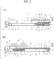
- Fig. 2 represents front views illustrating motion of a carriage of the sheet conveyance apparatus of Fig. 1
- Fig. 2(A) illustrates a state where the carriage is at a position at which the length of the sheet accumulation area is the shortest
- Fig. 2(B) illustrates a state where the carriage is at a position at which the length of the sheet accumulation area is the longest.
- the drive roller 1 has a horizontal rotary shaft 1a and four first pulleys (roller elements) 1b spaced apart from each other in the axis direction and attached to the rotary shaft 1a integrally with and rotatably about the rotary shaft 1a.
- the idle roller 2 has four second pulleys 2b (roller elements) arranged so as to be rotatable about a shaft 2a parallel to the rotary shaft 1a of the drive roller 1 and face the four first pulleys 1b, respectively.
- each endless conveyer belt 3 is stretched between the first pulley 1b of the drive roller 1 and the second pulley 2b of the idle roller 2 that are paired with each other.
- Each endless conveyer belt 3 has airflow holes 3a evenly over the entire length thereof.
- the first drive mechanism 4 has a pulley 4a fixed to one end of the rotary shaft 1a of the drive roller 1, a motor 4b whose drive shaft extends parallel to the drive roller 1, a pulley 4c fixed to the drive shaft of the motor 4b, and an endless belt 4d stretched between the pulley 4a and the pulley 4c.
- the four endless conveyer belts 3 simultaneously are rotated at a constant speed in response to the drive roller 1 being driven and rotated by the motor 4b, and the sheet S placed on the conveyer surfaces 3b of the four endless conveyer belts 3 is conveyed from the idle roller 2 side (the upstream end u of the conveyer surface 3b) to the drive roller 1 side (the downstream end w of the conveyer surface 3b).
- a carriage 8 arranged above the endless conveyer belts 3 so as to be able to reciprocate in the longitudinal direction of the endless conveyer belt 3, at least one (two in this embodiment) slide guide 9 that extends in the longitudinal direction of the endless conveyer belt 3 and to which the carriage 8 is slidably attached, and a second drive mechanism 10 that causes the carriage 8 to slide.
- the second drive mechanism 10 has a motor 10a and a pulley 10b spaced apart from each other in the longitudinal direction of the slide guide 9.
- the drive shaft of the motor 10a and the rotary shaft of the pulley 10b extend parallel to the drive roller 1 and the idle roller 2.
- a pulley 10c is fixed to the drive shaft of the motor 10a, and an endless belt 10d is stretched between the pulley 10c and the pulley 10b and extends parallel to the slide guide 9.
- the carriage 8 is fixed to the endless belt 10d.
- the carriage 8 may slide and reciprocate along the slide guide 9.
- a suction box 11 arranged between the upper and lower belt portions 3c and 3d of the four endless conveyer belts 3 so as to be able to reciprocate in the longitudinal direction of the endless conveyer belt 3 and a suction fan (intake source) 12 directly coupled to the suction box 11 and configured to generate a negative pressure inside the suction box 11.
- the suction box 11 is attached to the carriage 8. Further, the suction box 11 has intake holes 11a at positions in the upper surface above which respective endless conveyer belts 3 (the upper belt portions 3c) pass by and includes a shutter 11b therein that opens and closes the intake holes 11a.
- the shutter 11b is opened and closed at constant timings, and thereby suction through the intake holes 11a is performed at the constant timings.
- At least one (one in this embodiment) conveyance roller pair 13 extending across the conveyer surfaces 3b above the upstream end u of the conveyer surfaces 3b of the endless conveyer belts 3 and configured to take in the sheet S and feed out the sheet S onto the conveyer surfaces 3b and stopper plates 14 attached to the carriage 8 and extending across the conveyer surfaces 3b and upward from the conveyer surfaces 3b.
- the stopper plates 14 are separated into four parts in the longitudinal direction thereof, and each part of the stopper plates 14 corresponds to each endless conveyer belt 3.
- stopper plates 14 may be formed of a single stopper plate extending across the entire conveyer surfaces 3b of the four endless conveyer belts 3.
- the lower end 14a of the stopper plate 14 faces the suction box 11 and is arranged with a predetermined spacing from the conveyer surface 3b, and a region from the stopper plate 14 to the upstream end u of the conveyer surface 3b in the conveyer surface 3b forms a sheet accumulation area 15.
- the conveyance roller pair 16 is arranged at the downstream end w of the conveyer surfaces 3b and extends across the conveyer surfaces 3b.
- the conveyance roller pair 16 receives the sheet S from the downstream end w of the conveyer surfaces 3b and discharges the received sheet S to outside of the sheet conveyance apparatus.
- a discharge port of the upstream sheet processing apparatus is connected to the inlet side of the conveyance roller pair 13, and a feed port of the downstream sheet processing apparatus is connected to the outlet side of the conveyance roller pair 16.
- the position of the carriage 8, that is, of the stopper plate 14 and the suction box 11 is adjusted in accordance with the length of the sheet S to be conveyed (the length in the conveyance direction), and thereby the length of the sheet accumulation area 15 is adjusted.
- the lowermost sheet of the accumulated sheets is separated from the remaining sheets S by the suction box 11 one by one, conveyed by the endless conveyer belts 3 toward the downstream end w of the conveyer surface 3b through the spacing between the conveyer surface 3b and the stopper plate 14, and supplied to the downstream sheet processing apparatus by the conveyance roller pair 16.
- the sheet conveyance apparatus can temporarily accumulate the sheets S, which have been sequentially discharged from the upstream sheet processing apparatus, in the sheet accumulation area 15 and supply the lowermost sheet S out of the accumulated sheets S from the sheet accumulation area 15 to the downstream sheet processing apparatus one by one at timings synchronized with the processing speed of the downstream sheet processing apparatus.
- the sheet conveyance apparatus can facilitate smooth handover of the sheet S between the upstream and downstream sheet processing apparatuses.
- a mechanism to prevent contact between the accumulated lowermost sheet S and the conveyer surfaces 3b of the endless conveyer belts 3 is further provided in a region upstream of the upstream end 11c of the suction box 11 in the sheet accumulation area 15.
- the mechanism to prevent contact has five third pulleys (roller elements) 5 provided coaxially with the second pulleys 2b between adjacent second pulleys 2b of the idle roller 2 and outside the outermost second pulleys 2b and made rotatable about the shaft 2a.
- each third pulley 5 has a larger diameter than the second pulley 2b.
- the mechanism to prevent contact further has a cover sheet 17 that covers a region upstream of the suction box 11 in the sheet accumulation area 15.
- the cover sheet 17 has a width corresponding to the width of the sheet accumulation area 15 and a length that is equal to or larger than the length from the upstream end 11c of the suction box 11 to the upstream end u of the sheet accumulation area 15 when the length of the sheet accumulation area 15 is the largest.
- the mechanism to prevent contact further has two winding-type constant force plate springs 18 arranged at a fixed position under the downstream end of the endless conveyer belts 3.
- the one end 17a of the cover sheet 17 is fixed to the upstream end of the suction box 11 and extends across the sheet accumulation area 15, and the other end 17b of the cover sheet 17 extends to the winding-type constant force plate springs 18 via a part of the circumferential surface of the third pulleys 5 of the idle roller 2 and is attached to the end of each winding-type constant force plate spring 18.
- the cover sheet 17 is continually subjected to tension by the winding-type constant force plate springs 18 and continually tensed in a state of being spaced apart from the endless conveyer belts 3 even when the length of the sheet accumulation area 15 is changed. Further, even when the endless conveyer belts 3 are rotated, the cover sheet 17 is stationary in a tense state.
- any tensioner that can continually apply tension in the longitudinal direction of the cover sheet 17 can be used instead of the winding-type constant force plate springs 18.
- cover sheet 17 is arranged such that the other end 17b turns back along the circumferential surface of the third pulley 5 of the idle roller 2 and then extends along the lower side of the endless conveyer belts 3 in this embodiment, the arrangement of the cover sheet 17 is not limited to this embodiment and may be arrangement such that the other end 17b extends beyond the upstream end u parallel to the conveyer surface 3b, for example.
- the mechanism to prevent contact is provided as needed.
- Fig. 3 is a schematic plan view of a sheet conveyance apparatus according to another embodiment of the present invention
- Fig. 4(A) is a front view of the sheet conveyance apparatus of Fig. 3
- Fig. 4(B) is a plan view of a tensioner of the sheet conveyance apparatus of Fig. 4(A) when viewed in the X direction.
- Fig. 3 and Fig. 4 differs from the embodiment illustrated in Fig. 1 and Fig. 2 only in the configuration of the tensioner of the mechanism to prevent contact.
- the tensioner has a cover sheet winding roller 26 arranged under and parallel to a roller that is one of the drive roller 1 and the idle roller 2 which has the third pulley 5 (in this embodiment, the idle roller 2).
- the cover sheet winding roller 26 is formed of a body 26a and rotary shafts 26b and 26c projecting out of both ends of the body 26a, and a larger diameter portion 26d is provided to the rotary shaft 26b on one end side of the cover sheet winding roller 26.
- the one end 17a of the cover sheet 17 is fixed to the upstream end of the suction box 11 and extends across the sheet accumulation area 15.
- the other end 17b of the cover sheet 17 extends to the cover sheet winding roller 26 via a part of the circumferential surface of the third pulley 5 and is fixed to the circumferential surface of the cover sheet winding roller 26, and a certain length of the cover sheet 17 is wound on the cover sheet winding roller 26.
- the tensioner has a winding-type constant force plate spring 27 arranged at a fixed position in the lower side of the endless conveyer belts 3, and the fixed position is on the opposite side from the third pulley 5 with respect to the cover sheet winding roller 26 and on one end side (the rotary shaft 26b side) of the cover sheet winding roller 26.
- the winding-type constant force plate spring 27 is formed such that a winding part 27a is arranged so as to face the larger diameter portion 26d of the rotary shaft 26b and an end 27b is fixed to the circumferential surface of the larger diameter portion 26d to continually apply force to the cover sheet winding roller 26 in the winding direction of the cover sheet 17.
- the cover sheet 17 is continually subjected to tension by the tensioner (the cover sheet winding roller 26 and the winding-type constant force plate spring 27) and continually tensed in a state of being spaced apart from the endless conveyer belts 3 even when the length of the sheet accumulation area 15 is changed.
- the tensioner the cover sheet winding roller 26 and the winding-type constant force plate spring 27
- Fig. 5 is a schematic diagram of a sheet conveyance apparatus according to another embodiment of the present invention
- Fig. 5(A) is a plan view
- Fig. 5(B) is a front view.
- Fig. 5 differs from the embodiment illustrated in Fig. 1 only in the configuration of the mechanism to prevent contact.
- the mechanism to prevent contact has third pulleys (roller elements) 19 provided coaxially with the second pulleys 2b between adjacent second pulleys 2b of the idle roller 2 and outside the outermost second pulleys 2b and made rotatable about the shaft 2a.
- each third pulley 19 has a larger diameter than the second pulley 2b.
- the mechanism to prevent contact has fourth pulleys (roller elements) 20 provided coaxially with the first pulleys 1b between adjacent first pulleys 1b of the drive roller 1 and outside the outermost first pulleys 1b and made rotatable independently of the rotary shaft 1a.
- each fourth pulley 20 has a smaller diameter than the first pulley 1b.
- the mechanism to prevent contact further has additional endless belts 21 extending parallel to the endless conveyer belt 3 stretched between the paired third and fourth pulleys 19 and 20.
- the upper surface 21a of the additional endless belt 21 has a lower friction factor than the conveyer surface 3b of the endless conveyer belt 3.
- a guide 25 to guide the additional endless belts 21 is attached to the upstream end face of the suction box 11.
- the guide 25 has a horizontal guide roller 22 extending across the conveyer surfaces 3b at a position spaced apart from the upstream end face of the suction box 11 and a guide plate 23 extending parallel to the guide roller 22 on the opposite side from the suction box 11 with respect to the guide roller 22.
- the guide plate 23 has a cross section of an inverse L-shape with round corners.
- the guide roller 22 has a vertex located at substantially the same height as the upper surface of the suction box 11, and the guide plate 23 has a top face located at substantially the same height as the vertex of the third pulleys 19 of the idle roller 2.
- each additional endless belt 21 extends to the guide plate 23 in the conveyance direction from the third pulley 19, extends downward along the guide plate 23, then extends toward the upper edge of the upstream end face of the suction box 11 along the under surface of the guide roller 22, and then extends to the fourth pulley 20 along the upper surface of the suction box 11.
- a tension roller 24 extending across the additional endless belts 21 is arranged in the middle of the lower belt portions of the additional endless belts 21.
- the tension roller 24 continually maintains the additional endless belts 21 in a tense state even when the position of the carriage 8 (the stopper plate 24 and the suction box 11) is changed and the length of the sheet accumulation area 15 is thus changed.
- each endless belt 21 is located at a higher position than the conveyer surface 3b of the endless conveyer belt 3 in a region upstream of the suction box 11 in the sheet accumulation area 15 but is located at a lower position than the conveyer surface 3b of the endless conveyer belt 3 in a region overlapping the suction box 11 in the sheet accumulation area 15 and a region downstream of the sheet accumulation area 15 on the conveyer surface 3b.
- the additional endless belts 21 protrude out of the region upstream of the suction box 11 in the sheet accumulation area 15 on the conveyer surfaces 3b of the endless conveyer belts 3, and in this region, contact between the accumulated lowermost sheet S and the endless conveyer belts 3 is prevented.
- the additional endless belts 21 are stationary even when the endless conveyer belts 3 are rotated.
Landscapes
- Engineering & Computer Science (AREA)
- Mechanical Engineering (AREA)
- Delivering By Means Of Belts And Rollers (AREA)
- Pile Receivers (AREA)
Claims (6)
- Blattfördervorrichtung, umfassend:eine Antriebswalze (1) und eine Leerlaufwalze (2), die sich beide horizontal und parallel zueinander erstrecken;mindestens ein Endlosförderband (3), das zwischen der Antriebswalze (1) und der Leerlaufwalze (2) gespannt ist;einen ersten Antriebsmechanismus (4), der so konfiguriert ist, dass er die Antriebswalze (1) in Drehung versetzt;einen Saugkasten (11);mindestens ein Förderwalzenpaar (13), das sich oberhalb eines stromaufwärtigen Endes (u) einer Förderfläche (3b) des mindestens einen Endlosförderbands (3) und über die Förderfläche (3b) erstreckt und so konfiguriert ist, dass es ein Blatt (S) aufnimmt und das Blatt (S) auf die Förderfläche (3b) ausgibt; undeine Anschlagplatte (14), die sich quer über die Förderfläche (3b) und von der Förderfläche (3b) nach oben erstreckt, wobeiein unteres Ende (14a) der Anschlagplatte (14) dem Saugkasten (11) zugewandt und mit einem vorbestimmten Abstand von der Förderfläche (3b) angeordnet ist, und ein Bereich in der Förderfläche (3b) von der Anschlagplatte (14) bis zum stromaufwärtigen Ende (u) der Förderfläche (3b) einen Blattsammelbereich (15) ausbildet, und wobeiBlätter (S), die aus dem mindestens einen Förderwalzenpaar (13) herausgeführt werden, nacheinander in dem Blattsammelbereich (15) angesammelt werden, wenn jedes vordere Ende der Blätter (S) mit der Anschlagplatte (14) kollidiert, und das unterste Blatt der angesammelten Blätter eines nach dem anderen von den verbleibenden Blättern durch den Saugkasten (11) getrennt und durch das mindestens eine Endlosförderband (3) zu einem stromabwärtigen Ende (d) der Förderfläche (3b) durch den Zwischenraum zwischen der Förderfläche (3b) und der Anschlagplatte (14) befördert wird,dadurch gekennzeichnet, dass die Blattfördervorrichtung ferner Folgendes umfasst:einen Schlitten (8), der so angeordnet ist, dass er sich in einer Längsrichtung des Endlosförderbandes (3) über dem mindestens einen Endlosförderband (3) hin- und herbewegt;mindestens eine Gleitführung (9), die sich in Längsrichtung des Endlosförderbandes (3) erstreckt, wobei der Schlitten (8) an der mindestens einen Gleitführung (8) gleitend befestigt ist;einen zweiten Antriebsmechanismus (10), der so konfiguriert, dass er den Schlitten (8) verschiebt;
undeine Ansaugquelle (12), die so konfiguriert ist, dass sie einen Unterdruck im Inneren des Saugkastens (11) erzeugt,wobei der Saugkasten (11) so angeordnet ist, dass er sich in Längsrichtung des Endlosförderbandes (3) zwischen oberen (3c) und unteren Bandbereichen (3d) des mindestens einen Endlosförderbandes (3) hin und her bewegt,wobei die Anschlagplatte (14) an dem Schlitten (8) befestigt ist,wobei der Saugkasten (11) an dem Schlitten (8) befestigt ist und mindestens ein Einlassloch (11a) in einer dem oberen Bandbereich (3c) zugewandten Fläche aufweist, wobei eine Vielzahl von Luftstromlöchern (3a) in der Längsrichtung des mindestens einen Endlosförderbandes (3) an Positionen des mindestens einen Endlosförderbandes (3) vorgesehen sind, die während der Drehung des mindestens einen Endlosförderbandes (3) an dem mindestens einen Einlassloch (11a) vorbeilaufen. - Blattfördervorrichtung gemäß Anspruch 1, ferner umfassend:
einen Mechanismus zur Verhinderung eines Kontakts zwischen dem angesammelten untersten Blatt und der Förderfläche (3a) des mindestens einen Endlosförderbandes (3) in einem Bereich stromaufwärts des stromaufwärtigen Endes des Saugkastens (11) im Blattsammelbereich (15). - Blattfördervorrichtung gemäß Anspruch 2, wobei der Mechanismus zur Verhinderung eines Kontakts ein Abdeckblatt (17) aufweist, das einen Bereich stromaufwärts des Saugkastens (11) im Blattsammelbereich (15) abdeckt, wobeidas Abdeckblatt (17) eine Breite aufweist, die einer Breite des Blattsammelbereichs (15) entspricht, und eine Länge, die gleich oder größer ist als eine Länge von dem stromaufwärtigen Ende des Saugkastens (11) zu einem stromaufwärtigen Ende des Blattsammelbereiches (15), wenn eine Länge des Blattsammelbereiches (15) am größten ist, undein Ende (17a) des Abdeckblatts (17) am stromaufwärtigen Ende des Saugkastens (11) befestigt ist und sich über den Blattsammelbereich (15) erstreckt, und wobeider Mechanismus zur Verhinderung eines Kontakts ferner eine Spannvorrichtung aufweist, die an dem anderen Ende (17b) des Abdeckblatts (17) befestigt und so konfiguriert ist, dass sie kontinuierlich Spannung in einer Längsrichtung des Abdeckblatts (17) ausübt, unddas Abdeckblatt (17) in einem Zustand gespannt ist, in dem ein Bereich des Abdeckblatts, der das mindestens eine Endlosförderband (3) abdeckt, kontinuierlich von dem mindestens einen Endlosförderband (3) beabstandet ist.
- Blattfördervorrichtung gemäß Anspruch 3, wobei das mindestens eine Endlosförderband (3) eine Vielzahl von in Breitenrichtung voneinander beabstandeten Endlosförderbändern beinhaltet, wobeidie Antriebswalze (1)eine horizontale Drehwelle (1a) undeine Vielzahl von ersten Walzenelementen (1b) aufweist, die axial voneinander beabstandet sind und an der Drehwelle (1a) einstückig mit der Drehwelle (1a) und drehbar um diese befestigt sind, wobeidie Leerlaufwalze (2)eine Vielzahl von zweiten Walzenelementen (2b) aufweist, die so angeordnet sind, dass sie um eine parallele Welle (2a) parallel zur Drehwelle (1a) der Antriebswalze (1) drehbar sind und jeweils der Vielzahl von ersten Walzenelementen (1b) gegenüberliegen, undjedes der mehreren Endlosförderbänder (3) zwischen dem ersten (1b) und dem zweiten Walzenelement (2b), die miteinander gepaart sind, gespannt ist, und die Drehwelle (1a) der Antriebswalze durch den ersten Antriebsmechanismus (4) gedreht wird, wobeider Mechanismus zur Verhinderung eines Kontakts zwischen den nebeneinander liegenden ersten Walzenelementen (1b) oder den nebeneinander liegenden zweiten Walzenelementen (2b) ferner eine Walze aufweist, die eine der Antriebswalze (1) und der Leerlaufwalze (2) ist, die sich am stromaufwärtigen Ende (u) der Förderfläche (3b) und außerhalb des äußersten der ersten (1b) oder zweiten Walzenelemente (2b) befindet, eine Vielzahl von dritten Walzenelementen (19, 20), die jeweils koaxial zu den ersten (1b) oder zweiten Walzenelementen (2b) und unabhängig von der Drehwelle (1a) drehbar oder um die Parallelwelle (2a) drehbar vorgesehen sind, und jedes der dritten Walzenelemente (19, 20) einen größeren Durchmesser als jedes der ersten oder zweiten Walzenelemente aufweist, und wobeidie Spannvorrichtung mindestens eine wicklungsartige Konstantkraft-Tellerfeder (18) beinhaltet, die an einer festen Position unter dem mindestens einen Endlosförderband (3) angeordnet ist, und das andere Ende (17b) des Abdeckblatts (17) sich über einen Teil der Umfangsflächen der dritten Walzenelemente (5) zu der mindestens einen wicklungsartigen Konstantkraft-Tellerfeder (18) erstreckt und an einem Ende der mindestens einen wicklungsartigen Konstantkraft-Tellerfeder (18) befestigt ist.
- Blattfördervorrichtung gemäß Anspruch 3, wobeidas mindestens eine Endlosförderband (3) eine Vielzahl von in Breitenrichtung voneinander beabstandeten Endlosförderbändern (3) beinhaltet, wobeidie Antriebswalze (1)eine horizontale Drehwelle (1a) undeine Vielzahl von ersten Walzenelementen (1b) aufweist, die axial voneinander beabstandet sind und an der Drehwelle (1a) einstückig mit der Drehwelle (1a) und drehbar um diese befestigt sind, wobeidie Leerlaufwalze (2) eine Vielzahl von zweiten Walzenelementen (2b) aufweist, die so angeordnet sind, dass sie um eine zur Drehwelle (12a) der Antriebswalze (1) parallele Parallelwelle (2a) drehbar sind und jeweils der Vielzahl von ersten Walzenelementen gegenüberliegen, undjedes der Vielzahl von Endlosförderbändern (3) zwischen dem ersten (1b) und dem zweiten Walzenelement (2b), die miteinander gepaart sind, gespannt ist, und die Drehwelle (1a) der Antriebswalze (1) durch den ersten Antriebsmechanismus gedreht wird, wobeider Mechanismus zur Verhinderung eines Kontakts zwischen den nebeneinander liegenden ersten Walzenelementen (1b) oder den zweiten nebeneinander liegenden zweiten Walzenelementen (2b) ferner eine Walze aufweist, die eine der Antriebswalze (1) und der Leerlaufwalze (2) ist, die sich am stromaufwärtigen Ende (u) der Förderfläche (3b) und außerhalb des äußersten der ersten oder zweiten Walzenelemente (1b) befindet, eine Vielzahl von dritten Walzenelementen (5), die jeweils koaxial zu den ersten (1b) oder zweiten Walzenelementen (2b) und unabhängig von der Drehwelle (1a) oder um die Parallelwelle (2a) drehbar vorgesehen sind, und jedes der dritten Walzenelemente (5) einen größeren Durchmesser als jedes der betreffenden ersten (1b) oder zweiten Walzenelemente (2b) aufweist, wobeidie Spannvorrichtung eine Abdeckblattaufwickelwalze (26) aufweist, die unter und parallel zu einer Walze angeordnet ist, die eine der Antriebswalze (1) und der Leerlaufwalze (2) ist, die die dritten Walzenelemente (5) aufweist, unddas andere Ende (17b) des Abdeckblatts (17) sich über einen Teil der Umfangsflächen der dritten Walzenelemente (5) zu der Abdeckblattaufwickelwalze (26) erstreckt und an einer Umfangsfläche der Abdeckblattaufwickelwalze (26) befestigt ist, und wobeidie Spannvorrichtung ferner mindestens eine wicklungsartige Konstantkraft-Tellerfeder (18) aufweist, die an einer festen Position unter dem mindestens einen Endlosförderband (3) angeordnet ist, wobei sich die feste Position auf der den dritten Walzenelementen (5) gegenüberliegenden Seite in Bezug auf die Abdeckblattaufwickelwalze (26) und auf mindestens einer Endseite der Abdeckblattaufwickelwalze (26) befindet, ein Ende der wicklungsartigen Konstantkraft-Tellerfeder (18) an einer Drehwelle (26b) der Abdeckblattaufwickelwalze (26) befestigt ist, und die wicklungsartige Konstantkraft-Tellerfeder (18) kontinuierlich Kraft auf die Abdeckblattaufwickelwalze (26) in einer Wicklungsrichtung des Abdeckblatts (17) ausübt.
- Blattfördervorrichtung gemäß Anspruch 2, wobeidas mindestens eine Endlosförderband (3) eine Vielzahl von in Breitenrichtung voneinander beabstandeten Endlosförderbändern (3) beinhaltet, wobeidie Antriebswalze (1)eine horizontale Drehwelle (1a) undeine Vielzahl von ersten Walzenelementen (1b) aufweist, die axial voneinander beabstandet und einstückig mit der Drehwelle und um diese drehbar an dieser befestigt sind, wobeidie Leerlaufwalze (2) eine Vielzahl von zweiten Walzenelementen (2b) aufweist, die um eine zur Drehwelle (1a) parallele Parallelwelle (2a) drehbar angeordnet und der Vielzahl von ersten Walzenelementen (1b) zugewandt sind, und jeder der mehreren Endlosförderbänder (3) zwischen den miteinander ersten (1b) und zweiten Walzenelementen (2b) gespannt ist, die miteinander gepaart sind, und die Drehwelle (1a) der Antriebswalze (1) durch den ersten Antriebsmechanismus (4) gedreht wird, wobeider Mechanismus zur Verhinderung des Kontakts zwischen den nebeneinander liegenden ersten Walzenelementen (1b) oder den nebeneinander liegenden zweiten Walzenelementen (2b) einer Walze, die eine der Antriebswalze (1) und der Leerlaufwalze (2) ist, die sich am stromaufwärtigen Ende (u) der Förderfläche (3b) und außerhalb des äußersten der ersten (1b) oder zweiten Walzenelemente (2b) befindet, eine Vielzahl von dritten Walzenelementen (19), die jeweils koaxial zu den ersten (1b) oder zweiten Walzenelementen (2b) vorgesehen und unabhängig von der Drehwelle (1a) oder um die Parallelwelle (2b) drehbar sind, und jedes der dritten Walzenelemente (19) einen größeren Durchmesser als jedes der ersten (1b) oder zweiten Walzenelemente (2b) aufweist, wobeider Mechanismus zur Verhinderung eines Kontakts zwischen den nebeneinander liegenden ersten Walzenelementen (1b) oder den nebeneinander liegenden zweiten Walzenelementen (2b) ferner eine Walze aufweist, die eine der Antriebswalze (1) und der Leerlaufwalze (2) ist, die sich am stromabwärtigen Ende (d) der Förderfläche (3b) und außerhalb des äußersten der ersten (2b) oder zweiten Walzenelemente (2b) befindet, eine Vielzahl von vierten Walzenelementen (20), die jeweils koaxial zu den ersten (1b) oder zweiten Walzenelementen (2b) und unabhängig von der Drehwelle (1a) oder um die Parallelwelle (1b) drehbar vorgesehen sind, und jedes der vierten Walzenelemente (20) einen kleineren Durchmesser als jedes der ersten (1b) oder zweiten Walzenelemente (2b) aufweist, und wobeider Mechanismus zur Verhinderung eines Kontakts ferner ein zusätzliches Endlosband (21) aufweist, das zwischen den dritten (19) und den vierten Walzenelementen (20) gespannt ist, die miteinander gepaart sind und sich parallel zu den mehreren Endlosförderbändern (3) erstrecken, undeine obere Fläche (21a) des zusätzlichen Endlosbandes (21) einen geringeren Reibungsfaktor aufweist als entsprechende Förderflächen (3b) der Vielzahl von Endlosförderbändern (3), und die obere Fläche (21a) des zusätzlichen Endlosbandes (21) sich in einem Bereich stromaufwärts des Saugkastens (11) im Blattsammelbereich (15) an einer höheren Position befindet als die Förderflächen (3b) der Vielzahl von Endlosförderbändern (3) und sich an einer niedrigeren Position befindet als die Förderflächen (3b) der Vielzahl von Endlosförderbändern (3) in einem Bereich, der den Saugkasten (11) im Blattsammelbereich (15) und in einem Bereich stromabwärts des Blattsammelbereiches (15) auf den Förderflächen (3b) überlappt.
Applications Claiming Priority (2)
| Application Number | Priority Date | Filing Date | Title |
|---|---|---|---|
| JP2019185322 | 2019-10-08 | ||
| PCT/JP2020/028475 WO2021070450A1 (ja) | 2019-10-08 | 2020-07-22 | 用紙搬送装置 |
Publications (3)
| Publication Number | Publication Date |
|---|---|
| EP4043375A1 EP4043375A1 (de) | 2022-08-17 |
| EP4043375A4 EP4043375A4 (de) | 2023-10-18 |
| EP4043375B1 true EP4043375B1 (de) | 2024-11-06 |
Family
ID=75437095
Family Applications (1)
| Application Number | Title | Priority Date | Filing Date |
|---|---|---|---|
| EP20875080.2A Active EP4043375B1 (de) | 2019-10-08 | 2020-07-22 | Papierfördervorrichtung |
Country Status (5)
| Country | Link |
|---|---|
| US (1) | US11999583B2 (de) |
| EP (1) | EP4043375B1 (de) |
| JP (1) | JP7356182B2 (de) |
| CN (1) | CN114585577B (de) |
| WO (1) | WO2021070450A1 (de) |
Families Citing this family (1)
| Publication number | Priority date | Publication date | Assignee | Title |
|---|---|---|---|---|
| JP7489102B2 (ja) * | 2020-09-08 | 2024-05-23 | 株式会社ホリゾン | 用紙搬送装置及びその制御方法ならびに用紙搬送装置の制御プログラム |
Family Cites Families (16)
| Publication number | Priority date | Publication date | Assignee | Title |
|---|---|---|---|---|
| US4219191A (en) * | 1979-01-08 | 1980-08-26 | Pitney Bowes Inc. | Document feeding apparatus |
| FR2476615A1 (fr) | 1980-02-22 | 1981-08-28 | Martin Sa | Dispositif d'alimentation en feuilles d'une machine de traitement |
| US4382593A (en) * | 1980-08-04 | 1983-05-10 | International Business Machines Corporation | Vacuum document feeder |
| JPS5772532A (en) * | 1980-10-17 | 1982-05-06 | Ricoh Co Ltd | Suction head |
| JP2533957B2 (ja) | 1990-03-20 | 1996-09-11 | シャープ株式会社 | 重送防止機能付きシ―ト給送装置 |
| US5116040A (en) | 1990-04-06 | 1992-05-26 | De La Rue Giori S.A. | Sheet-feeder |
| JP2508544Y2 (ja) * | 1991-02-19 | 1996-08-28 | 三菱重工業株式会社 | 板紙給紙装置 |
| JPH0840582A (ja) * | 1994-07-29 | 1996-02-13 | Canon Inc | シート給送装置及びこれを備える画像形成装置 |
| US5836582A (en) | 1994-04-04 | 1998-11-17 | Canon Kabushiki Kaisha | Sheet feeding device with air injectors for separating sheets |
| US5954325A (en) * | 1996-06-04 | 1999-09-21 | Mita Industrial Co., Ltd. | Automatic document feeder |
| JP4169872B2 (ja) | 1999-07-13 | 2008-10-22 | ホリゾン・インターナショナル株式会社 | 用紙搬送装置 |
| WO2011100960A2 (de) | 2010-02-18 | 2011-08-25 | Trw Automotive Safety Systems Gmbh | Lenkrad mit gassackmodul |
| JP4886075B1 (ja) | 2011-01-31 | 2012-02-29 | 江沢事務器株式会社 | カット紙送給装置 |
| CN105173797B (zh) | 2015-10-16 | 2017-08-22 | 江南大学 | 全自动瓦楞对裱机 |
| JP2018002368A (ja) | 2016-06-30 | 2018-01-11 | 株式会社沖データ | 媒体供給装置 |
| CN109110527A (zh) | 2018-10-19 | 2019-01-01 | 湖南精正设备制造有限公司 | 一种利用负压吸附传动的自动化给纸机 |
-
2020
- 2020-07-22 JP JP2021550374A patent/JP7356182B2/ja active Active
- 2020-07-22 EP EP20875080.2A patent/EP4043375B1/de active Active
- 2020-07-22 CN CN202080070660.0A patent/CN114585577B/zh active Active
- 2020-07-22 US US17/766,974 patent/US11999583B2/en active Active
- 2020-07-22 WO PCT/JP2020/028475 patent/WO2021070450A1/ja not_active Ceased
Also Published As
| Publication number | Publication date |
|---|---|
| US11999583B2 (en) | 2024-06-04 |
| JP7356182B2 (ja) | 2023-10-04 |
| EP4043375A1 (de) | 2022-08-17 |
| CN114585577A (zh) | 2022-06-03 |
| WO2021070450A1 (ja) | 2021-04-15 |
| CN114585577B (zh) | 2023-10-27 |
| JPWO2021070450A1 (de) | 2021-04-15 |
| US20240076152A1 (en) | 2024-03-07 |
| EP4043375A4 (de) | 2023-10-18 |
Similar Documents
| Publication | Publication Date | Title |
|---|---|---|
| US9988231B2 (en) | Sheet conveying apparatus and image forming system including the same | |
| JP2017001788A (ja) | シート処理装置 | |
| JP5246637B2 (ja) | 用紙反転装置 | |
| EP4043375B1 (de) | Papierfördervorrichtung | |
| JPH11310363A (ja) | シ―トをスタック容器の中へ送出し、堆積させ、調整するための装置 | |
| US10017351B2 (en) | Sheet post-processing apparatus and image forming system | |
| JP2765652B2 (ja) | 感光材料整列装置 | |
| JP6532131B2 (ja) | シート処理装置及び画像形成システム | |
| US7150452B2 (en) | Waiting tray for sheet processing tray | |
| JPS59102761A (ja) | 用紙処理装置 | |
| JP7489102B2 (ja) | 用紙搬送装置及びその制御方法ならびに用紙搬送装置の制御プログラム | |
| CN106882632B (zh) | 纸张输送装置 | |
| JP2017200848A (ja) | 給紙装置および製本システム | |
| US6241236B1 (en) | Automated sheet delivery to selected paths using reversible crenellated roller | |
| JP6505184B2 (ja) | 紙葉類取り出し装置 | |
| JPS61217461A (ja) | 印刷装置の排紙案内装置 | |
| JP7186566B2 (ja) | シート束搬送ユニット及び後処理装置 | |
| JP3669570B2 (ja) | 用紙後処理装置 | |
| JP2010163235A (ja) | 用紙集積装置、用紙後処理装置及び画像形成システム | |
| WO2017195293A1 (ja) | 用紙搬送機、用紙加工装置、及び、用紙搬送方法 | |
| JP4549238B2 (ja) | 給紙装置 | |
| JP2023086984A (ja) | シート給送機構およびそれを備えるシート加工装置 | |
| JP4624185B2 (ja) | 紙葉類処理装置 | |
| JP6302270B2 (ja) | 紙葉類搬送装置 | |
| WO2010047376A1 (ja) | 印刷機の排紙装置及びその運転方法 |
Legal Events
| Date | Code | Title | Description |
|---|---|---|---|
| STAA | Information on the status of an ep patent application or granted ep patent |
Free format text: STATUS: THE INTERNATIONAL PUBLICATION HAS BEEN MADE |
|
| PUAI | Public reference made under article 153(3) epc to a published international application that has entered the european phase |
Free format text: ORIGINAL CODE: 0009012 |
|
| STAA | Information on the status of an ep patent application or granted ep patent |
Free format text: STATUS: REQUEST FOR EXAMINATION WAS MADE |
|
| 17P | Request for examination filed |
Effective date: 20220406 |
|
| AK | Designated contracting states |
Kind code of ref document: A1 Designated state(s): AL AT BE BG CH CY CZ DE DK EE ES FI FR GB GR HR HU IE IS IT LI LT LU LV MC MK MT NL NO PL PT RO RS SE SI SK SM TR |
|
| DAV | Request for validation of the european patent (deleted) | ||
| DAX | Request for extension of the european patent (deleted) | ||
| REG | Reference to a national code |
Ref country code: DE Free format text: PREVIOUS MAIN CLASS: B65H0031300000 Ref country code: DE Ref legal event code: R079 Ref document number: 602020041056 Country of ref document: DE Free format text: PREVIOUS MAIN CLASS: B65H0031300000 Ipc: B65H0003120000 |
|
| A4 | Supplementary search report drawn up and despatched |
Effective date: 20230919 |
|
| RIC1 | Information provided on ipc code assigned before grant |
Ipc: B65H 5/22 20060101ALI20230913BHEP Ipc: B65H 1/30 20060101ALI20230913BHEP Ipc: B65H 31/20 20060101ALI20230913BHEP Ipc: B65H 31/02 20060101ALI20230913BHEP Ipc: B65H 83/02 20060101ALI20230913BHEP Ipc: B65H 3/12 20060101AFI20230913BHEP |
|
| GRAP | Despatch of communication of intention to grant a patent |
Free format text: ORIGINAL CODE: EPIDOSNIGR1 |
|
| STAA | Information on the status of an ep patent application or granted ep patent |
Free format text: STATUS: GRANT OF PATENT IS INTENDED |
|
| INTG | Intention to grant announced |
Effective date: 20240627 |
|
| RIN1 | Information on inventor provided before grant (corrected) |
Inventor name: NAMBU, HIROMASA Inventor name: YACHI, TOMONORI Inventor name: AOKI, EIJI |
|
| GRAS | Grant fee paid |
Free format text: ORIGINAL CODE: EPIDOSNIGR3 |
|
| GRAA | (expected) grant |
Free format text: ORIGINAL CODE: 0009210 |
|
| STAA | Information on the status of an ep patent application or granted ep patent |
Free format text: STATUS: THE PATENT HAS BEEN GRANTED |
|
| AK | Designated contracting states |
Kind code of ref document: B1 Designated state(s): AL AT BE BG CH CY CZ DE DK EE ES FI FR GB GR HR HU IE IS IT LI LT LU LV MC MK MT NL NO PL PT RO RS SE SI SK SM TR |
|
| REG | Reference to a national code |
Ref country code: GB Ref legal event code: FG4D |
|
| REG | Reference to a national code |
Ref country code: CH Ref legal event code: EP |
|
| REG | Reference to a national code |
Ref country code: DE Ref legal event code: R096 Ref document number: 602020041056 Country of ref document: DE |
|
| REG | Reference to a national code |
Ref country code: IE Ref legal event code: FG4D |
|
| REG | Reference to a national code |
Ref country code: LT Ref legal event code: MG9D |
|
| REG | Reference to a national code |
Ref country code: NL Ref legal event code: MP Effective date: 20241106 |
|
| PG25 | Lapsed in a contracting state [announced via postgrant information from national office to epo] |
Ref country code: PT Free format text: LAPSE BECAUSE OF FAILURE TO SUBMIT A TRANSLATION OF THE DESCRIPTION OR TO PAY THE FEE WITHIN THE PRESCRIBED TIME-LIMIT Effective date: 20250306 Ref country code: IS Free format text: LAPSE BECAUSE OF FAILURE TO SUBMIT A TRANSLATION OF THE DESCRIPTION OR TO PAY THE FEE WITHIN THE PRESCRIBED TIME-LIMIT Effective date: 20250306 Ref country code: HR Free format text: LAPSE BECAUSE OF FAILURE TO SUBMIT A TRANSLATION OF THE DESCRIPTION OR TO PAY THE FEE WITHIN THE PRESCRIBED TIME-LIMIT Effective date: 20241106 |
|
| PG25 | Lapsed in a contracting state [announced via postgrant information from national office to epo] |
Ref country code: FI Free format text: LAPSE BECAUSE OF FAILURE TO SUBMIT A TRANSLATION OF THE DESCRIPTION OR TO PAY THE FEE WITHIN THE PRESCRIBED TIME-LIMIT Effective date: 20241106 Ref country code: NL Free format text: LAPSE BECAUSE OF FAILURE TO SUBMIT A TRANSLATION OF THE DESCRIPTION OR TO PAY THE FEE WITHIN THE PRESCRIBED TIME-LIMIT Effective date: 20241106 |
|
| REG | Reference to a national code |
Ref country code: AT Ref legal event code: MK05 Ref document number: 1739183 Country of ref document: AT Kind code of ref document: T Effective date: 20241106 |
|
| PG25 | Lapsed in a contracting state [announced via postgrant information from national office to epo] |
Ref country code: BG Free format text: LAPSE BECAUSE OF FAILURE TO SUBMIT A TRANSLATION OF THE DESCRIPTION OR TO PAY THE FEE WITHIN THE PRESCRIBED TIME-LIMIT Effective date: 20241106 |
|
| PG25 | Lapsed in a contracting state [announced via postgrant information from national office to epo] |
Ref country code: ES Free format text: LAPSE BECAUSE OF FAILURE TO SUBMIT A TRANSLATION OF THE DESCRIPTION OR TO PAY THE FEE WITHIN THE PRESCRIBED TIME-LIMIT Effective date: 20241106 |
|
| PG25 | Lapsed in a contracting state [announced via postgrant information from national office to epo] |
Ref country code: NO Free format text: LAPSE BECAUSE OF FAILURE TO SUBMIT A TRANSLATION OF THE DESCRIPTION OR TO PAY THE FEE WITHIN THE PRESCRIBED TIME-LIMIT Effective date: 20250206 |
|
| PG25 | Lapsed in a contracting state [announced via postgrant information from national office to epo] |
Ref country code: GR Free format text: LAPSE BECAUSE OF FAILURE TO SUBMIT A TRANSLATION OF THE DESCRIPTION OR TO PAY THE FEE WITHIN THE PRESCRIBED TIME-LIMIT Effective date: 20250207 Ref country code: LV Free format text: LAPSE BECAUSE OF FAILURE TO SUBMIT A TRANSLATION OF THE DESCRIPTION OR TO PAY THE FEE WITHIN THE PRESCRIBED TIME-LIMIT Effective date: 20241106 Ref country code: AT Free format text: LAPSE BECAUSE OF FAILURE TO SUBMIT A TRANSLATION OF THE DESCRIPTION OR TO PAY THE FEE WITHIN THE PRESCRIBED TIME-LIMIT Effective date: 20241106 |
|
| PG25 | Lapsed in a contracting state [announced via postgrant information from national office to epo] |
Ref country code: PL Free format text: LAPSE BECAUSE OF FAILURE TO SUBMIT A TRANSLATION OF THE DESCRIPTION OR TO PAY THE FEE WITHIN THE PRESCRIBED TIME-LIMIT Effective date: 20241106 |
|
| PG25 | Lapsed in a contracting state [announced via postgrant information from national office to epo] |
Ref country code: RS Free format text: LAPSE BECAUSE OF FAILURE TO SUBMIT A TRANSLATION OF THE DESCRIPTION OR TO PAY THE FEE WITHIN THE PRESCRIBED TIME-LIMIT Effective date: 20250206 |
|
| PG25 | Lapsed in a contracting state [announced via postgrant information from national office to epo] |
Ref country code: SM Free format text: LAPSE BECAUSE OF FAILURE TO SUBMIT A TRANSLATION OF THE DESCRIPTION OR TO PAY THE FEE WITHIN THE PRESCRIBED TIME-LIMIT Effective date: 20241106 |
|
| PG25 | Lapsed in a contracting state [announced via postgrant information from national office to epo] |
Ref country code: DK Free format text: LAPSE BECAUSE OF FAILURE TO SUBMIT A TRANSLATION OF THE DESCRIPTION OR TO PAY THE FEE WITHIN THE PRESCRIBED TIME-LIMIT Effective date: 20241106 |
|
| PG25 | Lapsed in a contracting state [announced via postgrant information from national office to epo] |
Ref country code: EE Free format text: LAPSE BECAUSE OF FAILURE TO SUBMIT A TRANSLATION OF THE DESCRIPTION OR TO PAY THE FEE WITHIN THE PRESCRIBED TIME-LIMIT Effective date: 20241106 |
|
| PG25 | Lapsed in a contracting state [announced via postgrant information from national office to epo] |
Ref country code: RO Free format text: LAPSE BECAUSE OF FAILURE TO SUBMIT A TRANSLATION OF THE DESCRIPTION OR TO PAY THE FEE WITHIN THE PRESCRIBED TIME-LIMIT Effective date: 20241106 |
|
| PG25 | Lapsed in a contracting state [announced via postgrant information from national office to epo] |
Ref country code: SK Free format text: LAPSE BECAUSE OF FAILURE TO SUBMIT A TRANSLATION OF THE DESCRIPTION OR TO PAY THE FEE WITHIN THE PRESCRIBED TIME-LIMIT Effective date: 20241106 |
|
| PG25 | Lapsed in a contracting state [announced via postgrant information from national office to epo] |
Ref country code: CZ Free format text: LAPSE BECAUSE OF FAILURE TO SUBMIT A TRANSLATION OF THE DESCRIPTION OR TO PAY THE FEE WITHIN THE PRESCRIBED TIME-LIMIT Effective date: 20241106 |
|
| PG25 | Lapsed in a contracting state [announced via postgrant information from national office to epo] |
Ref country code: IT Free format text: LAPSE BECAUSE OF FAILURE TO SUBMIT A TRANSLATION OF THE DESCRIPTION OR TO PAY THE FEE WITHIN THE PRESCRIBED TIME-LIMIT Effective date: 20241106 |
|
| REG | Reference to a national code |
Ref country code: DE Ref legal event code: R097 Ref document number: 602020041056 Country of ref document: DE |
|
| PG25 | Lapsed in a contracting state [announced via postgrant information from national office to epo] |
Ref country code: SE Free format text: LAPSE BECAUSE OF FAILURE TO SUBMIT A TRANSLATION OF THE DESCRIPTION OR TO PAY THE FEE WITHIN THE PRESCRIBED TIME-LIMIT Effective date: 20241106 |
|
| PLBE | No opposition filed within time limit |
Free format text: ORIGINAL CODE: 0009261 |
|
| STAA | Information on the status of an ep patent application or granted ep patent |
Free format text: STATUS: NO OPPOSITION FILED WITHIN TIME LIMIT |
|
| PGFP | Annual fee paid to national office [announced via postgrant information from national office to epo] |
Ref country code: DE Payment date: 20250722 Year of fee payment: 6 |
|
| 26N | No opposition filed |
Effective date: 20250807 |
|
| PGFP | Annual fee paid to national office [announced via postgrant information from national office to epo] |
Ref country code: GB Payment date: 20250724 Year of fee payment: 6 |
|
| PGFP | Annual fee paid to national office [announced via postgrant information from national office to epo] |
Ref country code: FR Payment date: 20250725 Year of fee payment: 6 |
|
| REG | Reference to a national code |
Ref country code: CH Ref legal event code: H13 Free format text: ST27 STATUS EVENT CODE: U-0-0-H10-H13 (AS PROVIDED BY THE NATIONAL OFFICE) Effective date: 20260224 |
|
| PG25 | Lapsed in a contracting state [announced via postgrant information from national office to epo] |
Ref country code: LU Free format text: LAPSE BECAUSE OF NON-PAYMENT OF DUE FEES Effective date: 20250722 |
|
| REG | Reference to a national code |
Ref country code: BE Ref legal event code: MM Effective date: 20250731 |
|
| PG25 | Lapsed in a contracting state [announced via postgrant information from national office to epo] |
Ref country code: BE Free format text: LAPSE BECAUSE OF NON-PAYMENT OF DUE FEES Effective date: 20250731 |
|
| PG25 | Lapsed in a contracting state [announced via postgrant information from national office to epo] |
Ref country code: CH Free format text: LAPSE BECAUSE OF NON-PAYMENT OF DUE FEES Effective date: 20250731 |