EP4043380A1 - Actionnement électromécanique par transmission flexible pour l'activation des parachutes d'ascenseur - Google Patents
Actionnement électromécanique par transmission flexible pour l'activation des parachutes d'ascenseur Download PDFInfo
- Publication number
- EP4043380A1 EP4043380A1 EP19816813.0A EP19816813A EP4043380A1 EP 4043380 A1 EP4043380 A1 EP 4043380A1 EP 19816813 A EP19816813 A EP 19816813A EP 4043380 A1 EP4043380 A1 EP 4043380A1
- Authority
- EP
- European Patent Office
- Prior art keywords
- wedge
- drive
- flexible transmission
- lift
- assembly
- Prior art date
- Legal status (The legal status is an assumption and is not a legal conclusion. Google has not performed a legal analysis and makes no representation as to the accuracy of the status listed.)
- Withdrawn
Links
- 230000005540 biological transmission Effects 0.000 title claims abstract description 34
- 230000002457 bidirectional effect Effects 0.000 claims abstract description 7
- 230000004913 activation Effects 0.000 claims description 12
- 230000001681 protective effect Effects 0.000 abstract description 3
- 238000001514 detection method Methods 0.000 description 4
- 230000001174 ascending effect Effects 0.000 description 2
- 238000004137 mechanical activation Methods 0.000 description 2
- 238000000034 method Methods 0.000 description 2
- 230000000717 retained effect Effects 0.000 description 2
- 230000003213 activating effect Effects 0.000 description 1
- 239000000654 additive Substances 0.000 description 1
- 238000013459 approach Methods 0.000 description 1
- 238000004891 communication Methods 0.000 description 1
- 230000000295 complement effect Effects 0.000 description 1
- 238000013461 design Methods 0.000 description 1
- 238000011161 development Methods 0.000 description 1
- 230000018109 developmental process Effects 0.000 description 1
- 230000005484 gravity Effects 0.000 description 1
- 238000012423 maintenance Methods 0.000 description 1
- 239000000463 material Substances 0.000 description 1
- 230000009347 mechanical transmission Effects 0.000 description 1
- 230000007246 mechanism Effects 0.000 description 1
- 238000012986 modification Methods 0.000 description 1
- 230000004048 modification Effects 0.000 description 1
- 230000008569 process Effects 0.000 description 1
- 230000000284 resting effect Effects 0.000 description 1
- 238000000926 separation method Methods 0.000 description 1
- 230000001629 suppression Effects 0.000 description 1
- 238000004804 winding Methods 0.000 description 1
Images



Classifications
-
- B—PERFORMING OPERATIONS; TRANSPORTING
- B66—HOISTING; LIFTING; HAULING
- B66B—ELEVATORS; ESCALATORS OR MOVING WALKWAYS
- B66B5/00—Applications of checking, fault-correcting, or safety devices in elevators
- B66B5/02—Applications of checking, fault-correcting, or safety devices in elevators responsive to abnormal operating conditions
- B66B5/16—Braking or catch devices operating between cars, cages, or skips and fixed guide elements or surfaces in hoistway or well
- B66B5/18—Braking or catch devices operating between cars, cages, or skips and fixed guide elements or surfaces in hoistway or well and applying frictional retarding forces
- B66B5/22—Braking or catch devices operating between cars, cages, or skips and fixed guide elements or surfaces in hoistway or well and applying frictional retarding forces by means of linearly-movable wedges
-
- B—PERFORMING OPERATIONS; TRANSPORTING
- B66—HOISTING; LIFTING; HAULING
- B66B—ELEVATORS; ESCALATORS OR MOVING WALKWAYS
- B66B5/00—Applications of checking, fault-correcting, or safety devices in elevators
- B66B5/02—Applications of checking, fault-correcting, or safety devices in elevators responsive to abnormal operating conditions
- B66B5/16—Braking or catch devices operating between cars, cages, or skips and fixed guide elements or surfaces in hoistway or well
- B66B5/18—Braking or catch devices operating between cars, cages, or skips and fixed guide elements or surfaces in hoistway or well and applying frictional retarding forces
- B66B5/20—Braking or catch devices operating between cars, cages, or skips and fixed guide elements or surfaces in hoistway or well and applying frictional retarding forces by means of rotatable eccentrically-mounted members
Definitions
- the object of this invention as stated in the title of the invention provides an electromechanical actuator by flexible transmission for the activation of lift safeties and which allows the positioning of one of the movable rollers for braking, serving both for unidirectional safeties as for bidirectional safeties.
- This invention is characterised by the special configuration and design of each of the elements of the electromechanical drive to achieve an effective and safe transmission between an electronic device for overspeed detection and an element that stops the lift car, allowing the same device to be activated both while ascending and descending or only when descending, depending on the configuration.
- This invention lies therefore within the field of lifts, and, in particular, safety measures used for emergency braking of a lift.
- the object of the present invention is an electromechanical drive by flexible transmission for lift safeties for braking, that is, the device object of the invention seeks mechanical activation for the lift emergency braking system known as lift safeties and which performs in a proactive manner, that is, a spring is responsible for maintaining the system in the activation position and a coil is responsible for maintaining the system inactivated or retained.
- the invention is the necessary interface between an electronic overspeed detection system and the element responsible for stopping the lift car in an emergency.
- the interface or transmission system between the electronic overspeed detection means that open a contact and the mobile rollers in charge of braking is the object of the search, and in this case said interface is carried out by means of a flexible transmission in the manner of a cable.
- the electromechanical drive by flexible transmission for braking using lift safeties comprises a bidirectional wedge assembly formed by two wedge rollers that run through oblong grooves made in a discrimination plate and are mounted on floating anchors and joined together by means of a spring, on the other hand it comprises a drive assembly comprising a coil characterised in that the transmission between the drive and the wedge assembly is carried out by means of a flexible transmission comprising two cables connected at one of its ends to the drive assembly and at the other end to the floating anchors on which the wedge rollers are mounted.
- the drive assembly comprises a coil, preferably double winding, on which a skid is connected and which in turn is connected to a mobile carriage balanced by two compensating springs joined at the lower vertices of the mobile carriage and on which joints between the mobile carriage and the compensating springs are connected each of the ends of the cable.
- the flexible electromechanical transmission mechanism works as described below.
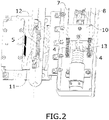
- Figures 1 to 5 show and progressively identify the different elements that are part of the electromechanical drive for braking lift safeties by means of flexible transmission, where the wedging means and the drive are assembled and joined together.
- Figure 6 shows a representation of the same previous elements except that the wedging means of the guide and the drive means are not mounted together, but separately.
- FIGS 1 to 4 show that the bidirectional electromechanical drive by flexible transmission comprises:
- Figure 5 shows the unidirectional version of the flexible drive and what it comprises.
- transmission means from the drive assembly to the set of wedges are flexible means, preferably cables.
- the means for adapting the transmission of the drive from the coil (3) to the transmission means comprise a mobile carriage (10) preferably rectangular in shape that has first ends of two compensating springs (4) attached at its lower corners, the mobile carriage (10) being linked to the end of the coil (3) by means of a skid (13), and where the flexible transmission means are joined on the first ends of the two compensating springs (4) at their junction with the mobile carriage (10).
- the flexible transmission means comprise two rods (7) and (8) that run between the joint of the end of the compensating spring (4) with the mobile carriage (10) and the floating anchors (14) and (15) of the wedge rollers (1) and (2).
- the system will carry a safety contact (9) that will cut the safety line.
- the maintenance solenoid can be connected to the encoder device or other positioning device and the more powerful solenoid can be connected to the control panel.
- solenoids we do not intend to limit the invention to a single actuator, since the activation could be functional with another element such as a single coil solenoid with an electric actuator.
- a discriminating plate (6) has been designed to discriminate between the directions of the lift car. This consists in a sheet with two slotted holes (17) and (18) through which the roller bolt runs. When the wedging has not occurred, the plate is resting by gravity on the bolt, butting against the upper position of the upper oblong. When the rollers are placed in the wedging position, the bolt of the rollers circulates along the oblong of the discriminating plate without opposition and when one of the rollers is wedged the other would move away since said plate would push the bolt of the other roller towards a non-interlocking position ( figure 3 ).
Landscapes
- Engineering & Computer Science (AREA)
- Mechanical Engineering (AREA)
- Maintenance And Inspection Apparatuses For Elevators (AREA)
- Braking Arrangements (AREA)
Applications Claiming Priority (1)
| Application Number | Priority Date | Filing Date | Title |
|---|---|---|---|
| PCT/ES2019/070672 WO2021069760A1 (fr) | 2019-10-07 | 2019-10-07 | Actionnement électromécanique par transmission flexible pour l'activation des parachutes d'ascenseur |
Publications (1)
| Publication Number | Publication Date |
|---|---|
| EP4043380A1 true EP4043380A1 (fr) | 2022-08-17 |
Family
ID=68808415
Family Applications (1)
| Application Number | Title | Priority Date | Filing Date |
|---|---|---|---|
| EP19816813.0A Withdrawn EP4043380A1 (fr) | 2019-10-07 | 2019-10-07 | Actionnement électromécanique par transmission flexible pour l'activation des parachutes d'ascenseur |
Country Status (5)
| Country | Link |
|---|---|
| US (1) | US11912536B2 (fr) |
| EP (1) | EP4043380A1 (fr) |
| KR (1) | KR20220074900A (fr) |
| CN (1) | CN114502496A (fr) |
| WO (1) | WO2021069760A1 (fr) |
Families Citing this family (4)
| Publication number | Priority date | Publication date | Assignee | Title |
|---|---|---|---|---|
| CN119212942A (zh) * | 2022-05-26 | 2024-12-27 | 戴纳泰克动力与科技有限公司 | 用于电梯安全钳的紧凑型机电启动系统 |
| CN115045487B (zh) * | 2022-07-22 | 2024-02-06 | 四川德宇泰达工程科技有限公司 | 一种升降式脚手架防坠制动装置及防护方法 |
| CN115839358A (zh) * | 2022-09-20 | 2023-03-24 | 泰兴市华诚机电制造有限公司 | 悬挂油缸后缸 |
| WO2026062302A1 (fr) * | 2025-07-09 | 2026-03-26 | Dynatech, Dynamics & Technology, S.L. | Actionneur électromécanique compact à robustesse et force augmentées pour parachute d'ascenseur |
Citations (5)
| Publication number | Priority date | Publication date | Assignee | Title |
|---|---|---|---|---|
| US2945561A (en) * | 1959-06-01 | 1960-07-19 | Universal Mfg Co | Elevator overspeed brake |
| JPS6443482A (en) * | 1987-08-07 | 1989-02-15 | Sanki Eng Co Ltd | Emergency stop device for elevator |
| WO2000039016A1 (fr) * | 1998-12-23 | 2000-07-06 | Otis Elevator Company | Systeme de securite electronique pour ascenseur |
| EP1048602A1 (fr) * | 1999-04-29 | 2000-11-02 | Sodimas | Dispositif parachute, notamment pour ascenseur et ascenseur ainsi équipé |
| WO2015126863A2 (fr) * | 2014-02-21 | 2015-08-27 | Wurtec Elevator Products & Services | Dispositif de cabine provisoire |
Family Cites Families (16)
| Publication number | Priority date | Publication date | Assignee | Title |
|---|---|---|---|---|
| EP0968954B1 (fr) * | 1998-07-03 | 2003-05-07 | Cobianchi Liftteile Ag | Dispositif parachute notamment pour cabines d'ascenseur |
| CN1121975C (zh) * | 2000-04-14 | 2003-09-24 | 中国建筑科学研究院建筑机械化研究分院 | 电梯双向安全钳 |
| EP1783086B1 (fr) * | 2005-11-08 | 2014-03-19 | Dynatech, Dynamics & Technology, S. L. | Dispositif de sécurité bidirectionnel progressif |
| ES2319706B1 (es) * | 2006-06-07 | 2009-12-09 | Thyssenkrupp Elevator Manufacturing Spain, S.L. | Aparato de frenado de emergencia de doble efecto para cabinas de ascensores. |
| CN201240733Y (zh) * | 2008-05-21 | 2009-05-20 | 河北东方富达机械有限公司 | 电梯安全制动装置 |
| WO2012038558A1 (fr) * | 2010-09-24 | 2012-03-29 | Dynatech, Dynamics & Technology, S.L. | Système intégré de pièces angulaires pour châssis d'ascenseur |
| DE202012104436U1 (de) * | 2012-11-16 | 2012-11-22 | Manfred Lienemann | Sicherheitseinrichtung für eine Aufzugkabine einer Aufzuganlage |
| CN103482448B (zh) * | 2013-09-18 | 2016-05-18 | 宁波赛富特电梯部件有限公司 | 双向安全钳 |
| DE102013111385A1 (de) * | 2013-10-15 | 2015-04-16 | Manfred Lienemann | Auslösevorrichtung einer Fangvorrichtung für eine Aufzugskabine einer Aufzugsanlage |
| FI125132B (fi) * | 2014-01-21 | 2015-06-15 | Kone Corp | Turvalaitejärjestelyllä varustettu hissi |
| CN106241549B (zh) * | 2016-08-30 | 2019-01-11 | 浙江西子富沃德电机有限公司 | 一种电梯用双向安全钳 |
| CN107445015B (zh) * | 2017-08-24 | 2023-03-24 | 佛山市昌宏电梯机械有限公司 | 一种电梯防下坠、超速、意外移动保护系统 |
| CN111392542B (zh) * | 2019-01-03 | 2024-05-07 | 杭州沪宁电梯部件股份有限公司 | 一种双向安全钳 |
| ES2956459T3 (es) * | 2019-08-29 | 2023-12-21 | Dynatech Dynamics & Tech S L | Dispositivo electromecánico bidireccional para la parada de emergencia de un ascensor |
| EP4103502B1 (fr) * | 2020-02-14 | 2025-11-05 | Wittur Holding GmbH | Unité de déclenchement pour actionner un dispositif de freinage d'ascenseur |
| CN119212942A (zh) * | 2022-05-26 | 2024-12-27 | 戴纳泰克动力与科技有限公司 | 用于电梯安全钳的紧凑型机电启动系统 |
-
2019
- 2019-10-07 KR KR1020227013300A patent/KR20220074900A/ko active Pending
- 2019-10-07 WO PCT/ES2019/070672 patent/WO2021069760A1/fr not_active Ceased
- 2019-10-07 EP EP19816813.0A patent/EP4043380A1/fr not_active Withdrawn
- 2019-10-07 CN CN201980101006.9A patent/CN114502496A/zh active Pending
- 2019-10-07 US US17/766,810 patent/US11912536B2/en active Active
Patent Citations (5)
| Publication number | Priority date | Publication date | Assignee | Title |
|---|---|---|---|---|
| US2945561A (en) * | 1959-06-01 | 1960-07-19 | Universal Mfg Co | Elevator overspeed brake |
| JPS6443482A (en) * | 1987-08-07 | 1989-02-15 | Sanki Eng Co Ltd | Emergency stop device for elevator |
| WO2000039016A1 (fr) * | 1998-12-23 | 2000-07-06 | Otis Elevator Company | Systeme de securite electronique pour ascenseur |
| EP1048602A1 (fr) * | 1999-04-29 | 2000-11-02 | Sodimas | Dispositif parachute, notamment pour ascenseur et ascenseur ainsi équipé |
| WO2015126863A2 (fr) * | 2014-02-21 | 2015-08-27 | Wurtec Elevator Products & Services | Dispositif de cabine provisoire |
Non-Patent Citations (1)
| Title |
|---|
| See also references of WO2021069760A1 * |
Also Published As
| Publication number | Publication date |
|---|---|
| WO2021069760A1 (fr) | 2021-04-15 |
| KR20220074900A (ko) | 2022-06-03 |
| US11912536B2 (en) | 2024-02-27 |
| US20230047036A1 (en) | 2023-02-16 |
| CN114502496A (zh) | 2022-05-13 |
Similar Documents
| Publication | Publication Date | Title |
|---|---|---|
| EP4043380A1 (fr) | Actionnement électromécanique par transmission flexible pour l'activation des parachutes d'ascenseur | |
| EP3569547B1 (fr) | Ensemble de sécurité pour freiner une cabine d'ascenseur et procédé correspondant | |
| KR101033378B1 (ko) | 엘리베이터의 안전장치 | |
| EP3147248B1 (fr) | Système de freinage pour structure hissée et procédé de contrôle de freinage de structure hissée | |
| EP2571799B1 (fr) | Système de sécurité intégré pour ascenseur | |
| CN103492302A (zh) | 具有制动器释放特征的电梯制动器 | |
| EP3566993B1 (fr) | Synchronisation basée sur la distance d'un ensemble d'aimants au rail | |
| CN111712455A (zh) | 紧急停止装置及电梯 | |
| EP3789335B1 (fr) | Dispositif d'engrenage de sécurité électromécanique pour appareil d'ascenseur | |
| EP3766816B1 (fr) | Dispositif électromécanique unidirectionnel d'arrêt d'urgence d'ascenseur | |
| EP3674248B1 (fr) | Frein de stationnement de cabine d'ascenseur | |
| EP4056511B1 (fr) | Dispositif d'ascenseur | |
| EP3789333A1 (fr) | Actionnement électromécanique d'un dispositif bidirectionnel d'arrêt d'urgence d'un ascenseur | |
| CN105480811A (zh) | 夹绳器 | |
| CN114291688A (zh) | 安全制动器装置 | |
| EP4177207B1 (fr) | Actionneur de sécurité électronique sans friction | |
| EP3789334A1 (fr) | Dispositif de freinage pour appareil élévateur et procédé de freinage associé | |
| US20200346895A1 (en) | Combined safety brake and safety actuation mechanism | |
| HK1236175A1 (en) | Braking system for a hoisted structure and method of controlling braking a hoisted structure | |
| HK1193387A (en) | Elevator brake having a brake release feature |
Legal Events
| Date | Code | Title | Description |
|---|---|---|---|
| STAA | Information on the status of an ep patent application or granted ep patent |
Free format text: STATUS: UNKNOWN |
|
| STAA | Information on the status of an ep patent application or granted ep patent |
Free format text: STATUS: THE INTERNATIONAL PUBLICATION HAS BEEN MADE |
|
| PUAI | Public reference made under article 153(3) epc to a published international application that has entered the european phase |
Free format text: ORIGINAL CODE: 0009012 |
|
| STAA | Information on the status of an ep patent application or granted ep patent |
Free format text: STATUS: REQUEST FOR EXAMINATION WAS MADE |
|
| 17P | Request for examination filed |
Effective date: 20220428 |
|
| AK | Designated contracting states |
Kind code of ref document: A1 Designated state(s): AL AT BE BG CH CY CZ DE DK EE ES FI FR GB GR HR HU IE IS IT LI LT LU LV MC MK MT NL NO PL PT RO RS SE SI SK SM TR |
|
| DAV | Request for validation of the european patent (deleted) | ||
| DAX | Request for extension of the european patent (deleted) | ||
| GRAP | Despatch of communication of intention to grant a patent |
Free format text: ORIGINAL CODE: EPIDOSNIGR1 |
|
| STAA | Information on the status of an ep patent application or granted ep patent |
Free format text: STATUS: GRANT OF PATENT IS INTENDED |
|
| INTG | Intention to grant announced |
Effective date: 20240111 |
|
| STAA | Information on the status of an ep patent application or granted ep patent |
Free format text: STATUS: THE APPLICATION IS DEEMED TO BE WITHDRAWN |
|
| 18D | Application deemed to be withdrawn |
Effective date: 20240514 |