EP4043423A1 - System und verfahren zur herstellung von biomethanol - Google Patents
System und verfahren zur herstellung von biomethanol Download PDFInfo
- Publication number
- EP4043423A1 EP4043423A1 EP22156989.0A EP22156989A EP4043423A1 EP 4043423 A1 EP4043423 A1 EP 4043423A1 EP 22156989 A EP22156989 A EP 22156989A EP 4043423 A1 EP4043423 A1 EP 4043423A1
- Authority
- EP
- European Patent Office
- Prior art keywords
- mol
- methanol
- biomethanol
- stream
- carbon dioxide
- Prior art date
- Legal status (The legal status is an assumption and is not a legal conclusion. Google has not performed a legal analysis and makes no representation as to the accuracy of the status listed.)
- Pending
Links
Images


Classifications
-
- C—CHEMISTRY; METALLURGY
- C07—ORGANIC CHEMISTRY
- C07C—ACYCLIC OR CARBOCYCLIC COMPOUNDS
- C07C29/00—Preparation of compounds having hydroxy or O-metal groups bound to a carbon atom not belonging to a six-membered aromatic ring
- C07C29/15—Preparation of compounds having hydroxy or O-metal groups bound to a carbon atom not belonging to a six-membered aromatic ring by reduction of oxides of carbon exclusively
- C07C29/151—Preparation of compounds having hydroxy or O-metal groups bound to a carbon atom not belonging to a six-membered aromatic ring by reduction of oxides of carbon exclusively with hydrogen or hydrogen-containing gases
- C07C29/1512—Preparation of compounds having hydroxy or O-metal groups bound to a carbon atom not belonging to a six-membered aromatic ring by reduction of oxides of carbon exclusively with hydrogen or hydrogen-containing gases characterised by reaction conditions
-
- C—CHEMISTRY; METALLURGY
- C07—ORGANIC CHEMISTRY
- C07C—ACYCLIC OR CARBOCYCLIC COMPOUNDS
- C07C29/00—Preparation of compounds having hydroxy or O-metal groups bound to a carbon atom not belonging to a six-membered aromatic ring
- C07C29/15—Preparation of compounds having hydroxy or O-metal groups bound to a carbon atom not belonging to a six-membered aromatic ring by reduction of oxides of carbon exclusively
- C07C29/151—Preparation of compounds having hydroxy or O-metal groups bound to a carbon atom not belonging to a six-membered aromatic ring by reduction of oxides of carbon exclusively with hydrogen or hydrogen-containing gases
- C07C29/1516—Multisteps
- C07C29/1518—Multisteps one step being the formation of initial mixture of carbon oxides and hydrogen for synthesis
-
- B—PERFORMING OPERATIONS; TRANSPORTING
- B01—PHYSICAL OR CHEMICAL PROCESSES OR APPARATUS IN GENERAL
- B01J—CHEMICAL OR PHYSICAL PROCESSES, e.g. CATALYSIS OR COLLOID CHEMISTRY; THEIR RELEVANT APPARATUS
- B01J19/00—Chemical, physical or physico-chemical processes in general; Their relevant apparatus
- B01J19/24—Stationary reactors without moving elements inside
- B01J19/2455—Stationary reactors without moving elements inside provoking a loop type movement of the reactants
- B01J19/2465—Stationary reactors without moving elements inside provoking a loop type movement of the reactants externally, i.e. the mixture leaving the vessel and subsequently re-entering it
-
- B—PERFORMING OPERATIONS; TRANSPORTING
- B01—PHYSICAL OR CHEMICAL PROCESSES OR APPARATUS IN GENERAL
- B01J—CHEMICAL OR PHYSICAL PROCESSES, e.g. CATALYSIS OR COLLOID CHEMISTRY; THEIR RELEVANT APPARATUS
- B01J19/00—Chemical, physical or physico-chemical processes in general; Their relevant apparatus
- B01J19/24—Stationary reactors without moving elements inside
- B01J19/2475—Membrane reactors
-
- C—CHEMISTRY; METALLURGY
- C07—ORGANIC CHEMISTRY
- C07C—ACYCLIC OR CARBOCYCLIC COMPOUNDS
- C07C29/00—Preparation of compounds having hydroxy or O-metal groups bound to a carbon atom not belonging to a six-membered aromatic ring
- C07C29/15—Preparation of compounds having hydroxy or O-metal groups bound to a carbon atom not belonging to a six-membered aromatic ring by reduction of oxides of carbon exclusively
- C07C29/151—Preparation of compounds having hydroxy or O-metal groups bound to a carbon atom not belonging to a six-membered aromatic ring by reduction of oxides of carbon exclusively with hydrogen or hydrogen-containing gases
- C07C29/152—Preparation of compounds having hydroxy or O-metal groups bound to a carbon atom not belonging to a six-membered aromatic ring by reduction of oxides of carbon exclusively with hydrogen or hydrogen-containing gases characterised by the reactor used
-
- C—CHEMISTRY; METALLURGY
- C07—ORGANIC CHEMISTRY
- C07C—ACYCLIC OR CARBOCYCLIC COMPOUNDS
- C07C29/00—Preparation of compounds having hydroxy or O-metal groups bound to a carbon atom not belonging to a six-membered aromatic ring
- C07C29/74—Separation; Purification; Use of additives, e.g. for stabilisation
- C07C29/76—Separation; Purification; Use of additives, e.g. for stabilisation by physical treatment
-
- B—PERFORMING OPERATIONS; TRANSPORTING
- B01—PHYSICAL OR CHEMICAL PROCESSES OR APPARATUS IN GENERAL
- B01J—CHEMICAL OR PHYSICAL PROCESSES, e.g. CATALYSIS OR COLLOID CHEMISTRY; THEIR RELEVANT APPARATUS
- B01J19/00—Chemical, physical or physico-chemical processes in general; Their relevant apparatus
- B01J19/24—Stationary reactors without moving elements inside
- B01J19/248—Reactors comprising multiple separated flow channels
-
- B—PERFORMING OPERATIONS; TRANSPORTING
- B01—PHYSICAL OR CHEMICAL PROCESSES OR APPARATUS IN GENERAL
- B01J—CHEMICAL OR PHYSICAL PROCESSES, e.g. CATALYSIS OR COLLOID CHEMISTRY; THEIR RELEVANT APPARATUS
- B01J2219/00—Chemical, physical or physico-chemical processes in general; Their relevant apparatus
- B01J2219/00049—Controlling or regulating processes
- B01J2219/00051—Controlling the temperature
- B01J2219/00121—Controlling the temperature by direct heating or cooling
-
- C—CHEMISTRY; METALLURGY
- C01—INORGANIC CHEMISTRY
- C01B—NON-METALLIC ELEMENTS; COMPOUNDS THEREOF; METALLOIDS OR COMPOUNDS THEREOF NOT COVERED BY SUBCLASS C01C
- C01B2203/00—Integrated processes for the production of hydrogen or synthesis gas
- C01B2203/02—Processes for making hydrogen or synthesis gas
- C01B2203/0205—Processes for making hydrogen or synthesis gas containing a reforming step
- C01B2203/0211—Processes for making hydrogen or synthesis gas containing a reforming step containing a non-catalytic reforming step
- C01B2203/0222—Processes for making hydrogen or synthesis gas containing a reforming step containing a non-catalytic reforming step containing a non-catalytic carbon dioxide reforming step
-
- C—CHEMISTRY; METALLURGY
- C01—INORGANIC CHEMISTRY
- C01B—NON-METALLIC ELEMENTS; COMPOUNDS THEREOF; METALLOIDS OR COMPOUNDS THEREOF NOT COVERED BY SUBCLASS C01C
- C01B2203/00—Integrated processes for the production of hydrogen or synthesis gas
- C01B2203/04—Integrated processes for the production of hydrogen or synthesis gas containing a purification step for the hydrogen or the synthesis gas
- C01B2203/0415—Purification by absorption in liquids
-
- C—CHEMISTRY; METALLURGY
- C01—INORGANIC CHEMISTRY
- C01B—NON-METALLIC ELEMENTS; COMPOUNDS THEREOF; METALLOIDS OR COMPOUNDS THEREOF NOT COVERED BY SUBCLASS C01C
- C01B2203/00—Integrated processes for the production of hydrogen or synthesis gas
- C01B2203/04—Integrated processes for the production of hydrogen or synthesis gas containing a purification step for the hydrogen or the synthesis gas
- C01B2203/0465—Composition of the impurity
- C01B2203/0475—Composition of the impurity the impurity being carbon dioxide
-
- C—CHEMISTRY; METALLURGY
- C01—INORGANIC CHEMISTRY
- C01B—NON-METALLIC ELEMENTS; COMPOUNDS THEREOF; METALLOIDS OR COMPOUNDS THEREOF NOT COVERED BY SUBCLASS C01C
- C01B2203/00—Integrated processes for the production of hydrogen or synthesis gas
- C01B2203/06—Integration with other chemical processes
- C01B2203/061—Methanol production
-
- C—CHEMISTRY; METALLURGY
- C01—INORGANIC CHEMISTRY
- C01B—NON-METALLIC ELEMENTS; COMPOUNDS THEREOF; METALLOIDS OR COMPOUNDS THEREOF NOT COVERED BY SUBCLASS C01C
- C01B2203/00—Integrated processes for the production of hydrogen or synthesis gas
- C01B2203/14—Details of the flowsheet
- C01B2203/148—Details of the flowsheet involving a recycle stream to the feed of the process for making hydrogen or synthesis gas
-
- C—CHEMISTRY; METALLURGY
- C01—INORGANIC CHEMISTRY
- C01B—NON-METALLIC ELEMENTS; COMPOUNDS THEREOF; METALLOIDS OR COMPOUNDS THEREOF NOT COVERED BY SUBCLASS C01C
- C01B2203/00—Integrated processes for the production of hydrogen or synthesis gas
- C01B2203/80—Aspect of integrated processes for the production of hydrogen or synthesis gas not covered by groups C01B2203/02 - C01B2203/1695
- C01B2203/86—Carbon dioxide sequestration
Definitions
- Biomethanol may be produced by first reacting biogas (containing methane, water, and carbon dioxide) in a reformer reactor under high temperature and low-pressure conditions to create a syngas mixture containing hydrogen and carbon monoxide. Then, the syngas mixture is reacted in a methanol reactor under high-pressure and lower temperature conditions to create biomethanol.
- biogas contains a surplus of carbon dioxide-more than is needed to yield efficient stoichiometric reactions. In effect, the excess carbon dioxide may reduce the overall system efficiency, leading to reduced biomethanol yields and/or higher operating costs for the system.
- the art recognizes the need for a method of removing surplus carbon dioxide from the biomethanol production system without requiring additional reactants to be supplied to the system.
- a biomethanol production system comprises (a) a feed stream comprising methane, water, and carbon dioxide; (b) a reformer reactor capable of reacting the feed stream to form a syngas mixture comprising hydrogen, carbon monoxide, and carbon dioxide; (c) a methanol reactor capable of reacting the syngas mixture to form biomethanol product; (d) a wash column comprising the syngas mixture and the biomethanol product, wherein the biomethanol product is capable of absorbing carbon dioxide from the syngas mixture; and (e) a flash column comprising a vent capable of venting the absorbed carbon dioxide.
- the biomethanol production system includes (f) a methanol recycle stream that puts the flash column in fluid communication with the wash column, the methanol recycle stream comprising biomethanol discharged from the flash column; and (g) a CO 2 -methanol line that puts the wash column in fluid communication with the flash column, the CO 2 -methanol line comprising the carbon dioxide absorbed in the biomethanol product discharged from the wash column.
- the CO 2 -methanol line comprises at least 100% more carbon dioxide than the methanol recycle stream, based on the total moles of carbon dioxide contained in the respective stream.
- the ratio of moles of carbon dioxide in the CO 2 -methanol line to the moles of carbon dioxide in the methanol recycle stream is from 1.2:1 to 50:1.
- the biomethanol production system includes (h) a wash process stream discharge line that puts the wash column in fluid communication with the methanol reactor, the wash process stream discharge line comprising syngas mixture discharged from the wash column.
- the wash process stream discharge line comprises at least 50% less carbon dioxide than the syngas mixture formed in the reformer reactor.
- the ratio of moles of carbon dioxide in the syngas mixture formed in the reformer reactor to the moles of carbon dioxide in the wash process stream discharge line is from 80:1 to 35:1.
- the biomethanol production system comprises (a) a feed stream; (b) a reformer reactor configured to react the feed stream to create a syngas mixture; (c) a methanol reactor configured to react the syngas mixture to form a biomethanol product; and (d) a wash column configured to absorb carbon dioxide from the syngas mixture.
- the biomethanol production system may further comprise (e) a device configured to release the absorbed carbon dioxide from the biomethanol stream and vent the absorbed carbon dioxide from the biomethanol production system.
- the device in step (e) may be provided as a flash column comprising a vent capable of venting the absorbed carbon dioxide.
- the biomethanol system further comprises (f) a methanol recycle stream that puts the device in fluid communication with the wash column, the methanol recycle stream comprising biomethanol discharged from the device of step (e); and (g) a CO 2 -methanol line that puts the wash column in fluid communication with the device, the CO 2 -methanol line comprising the carbon dioxide absorbed in the biomethanol product discharged from the wash column.
- the biomethanol system may further comprise (h) a wash process stream discharge line that puts the wash column in fluid communication with the methanol reactor, the wash process stream discharge line comprising syngas mixture discharged from the wash column.
- the wash column is upstream of the methanol reactor. In other embodiments of the biomethanol production system, the wash column is positioned between a first methanol reactor and a second methanol reactor.
- the biomethanol production system recycles at least two times, or at least three times, or at least ten times, or at least twenty times, or at least thirty times, or at least forty times, or at least forty-five times the amount of methanol that is recovered.
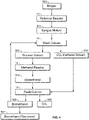
- a method for removing carbon dioxide from a biomethanol production system includes (a) reacting biogas in a reformer reactor to form a syngas mixture comprising hydrogen, carbon monoxide, and carbon dioxide; (b) feeding the syngas mixture to a wash column and forming a process stream; (c) feeding the process stream to a first methanol reactor and reacting the process stream to form biomethanol; (d) feeding the biomethanol from the first methanol reactor to a flash column and then to the wash column; (e) absorbing carbon dioxide from the syngas mixture in the wash column with the biomethanol to form a CO 2 -methanol stream; and (f) recycling the CO 2 -methanol stream by feeding it to the flash column and releasing the absorbed carbon dioxide.
- the carbon dioxide released in step (f) is vented from the flash column.
- a second methanol reactor is positioned between the first methanol reactor and the flash column.
- the above-described method excludes at least one of: (i) treating the syngas mixture, the biomethanol, and the CO 2 -methanol stream with amines; and (ii) treating the syngas mixture, the biomethanol, and the CO 2 -methanol stream with a membrane configured to isolate carbon dioxide from components of the syngas mixture, the biomethanol, and the CO 2 -methanol stream.
- the method includes (a) providing a biogas comprising methane, water, and carbon dioxide; (b) reacting the biogas in a reformer reactor to form a syngas mixture comprising hydrogen, carbon monoxide, and carbon dioxide; (c) feeding the syngas mixture to a wash column and forming a process stream, wherein the process stream contains less carbon dioxide than the syngas mixture; (d) feeding the process stream to a methanol reactor and reacting the contents of the process stream to form biomethanol; (e) feeding the biomethanol from the methanol reactor to a flash column; (f) feeding the biomethanol from the flash column to the wash column; (g) absorbing carbon dioxide from the syngas mixture in the wash column with the biomethanol from the flash column to form a CO 2 -methanol stream, wherein the CO 2 -methanol stream contains more carbon dioxide than the biomethanol from the flash column; (h) feeding the CO 2 -methanol stream to the flash column and
- the CO 2 -methanol stream contains at least 100% more carbon dioxide than the biomethanol from the flash column, based on the total moles of carbon dioxide contained in the respective stream.
- the ratio of moles of carbon dioxide in the CO 2 -methanol stream to the moles of carbon dioxide in the biomethanol from the flash column is from 10:1 to 50:1.
- either of the methods for removing carbon dioxide from a biomethanol production system excludes treating the syngas mixture, the biomethanol, and the CO 2 -methanol stream with amines.
- either of the methods for removing carbon dioxide from a biomethanol production system excludes treating the syngas mixture, the biomethanol, and the CO 2 -methanol stream with a membrane configured to isolate carbon dioxide from the respective stream components.
- either of the methods for removing carbon dioxide from a biomethanol production system includes recycling at least two times, or at least three times, or at least ten times, or at least twenty times, or at least thirty times, or at least forty times, or at least forty-five times the amount of methanol that is recovered.
- the numerical ranges disclosed herein include all values from, and including, the lower and upper value.
- ranges containing explicit values e.g., a range from 1, or 2, or 3 to 5, or 6, or 7
- any subrange between any two explicit values is included (e.g., the range 1-7 above includes subranges 1 to 2; 2 to 6; 5 to 7; 3 to 7; 5 to 6; etc.).
- line refers to a physical connection between two points.
- suitable lines include tubes and pipes.
- stream refers to the composition, mixture, or component, contained within and/or passing through a line. It is understood that the terms “line” and “stream” may be used interchangeably herein, such that, for example, the feed line may be referred to herein as the feed stream (and vice versa).
- methanol refers to methyl alcohol, also known as CH 3 OH.
- a nonlimiting example of methanol is biomethanol.
- biomethanol refers to a type of methanol that is produced by gasification of organic material (such as biomass, solid waste, coal, or carbon dioxide) to synthesis gas (also known as syngas), followed by methanol synthesis.
- organic material such as biomass, solid waste, coal, or carbon dioxide
- synthesis gas also known as syngas
- biomethanol is produced using biogas.
- Biogas refers to a mixture of gases produced by the breakdown of organic material in the absence of oxygen.
- suitable biogas include landfill gas, gas from sewage and/or industrial wastewater treatment, and gas from animal waste.
- the biogas is a mixture of gases including methane, carbon dioxide, nitrogen, and hydrogen. While the present application refers to a biomethanol production system and method, it is understood that it may also be used as a methanol production system and method.
- a biomethanol production system comprises (a) a feed stream comprising methane, water, and carbon dioxide; (b) a reformer reactor capable of reacting the feed stream to form a syngas mixture comprising hydrogen, carbon monoxide, and carbon dioxide; (c) a methanol reactor capable of reacting the syngas mixture to form biomethanol product; (d) a wash column comprising the syngas mixture and the biomethanol product, wherein the biomethanol product is capable of absorbing carbon dioxide from the syngas mixture; and (e) a flash column comprising a vent capable of venting the absorbed carbon dioxide.
- carbon dioxide is removed without requiring the addition of a separate component feed (e.g., hydrogen or a solvent such as water), or a membrane to remove the carbon dioxide, or pressure swing absorption.
- a separate component feed e.g., hydrogen or a solvent such as water
- the biomethanol production system may remove carbon dioxide from the process by using at least a portion of the methanol product produced by the biomethanol production system. Removal of carbon dioxide in this manner may increase the efficiency of the system, thereby presenting an opportunity for significant cost savings for the system operator.
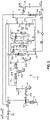
- the biomethanol production system 10 includes at least a reformer reactor 12, a methanol reactor 14, a wash column 16, and a flash column 18.
- the reformer reactor 12 is provided in fluid communication with a gas source 20.
- the gas source 20 may be a reservoir of a gas mixture.
- the gas source 20 may include biogas comprising a variety of components (e.g., methane, carbon dioxide, nitrogen, water, hydrogen, etc.).
- the biogas may be produced from sources including, but not limited to, as agricultural waste, manure, municipal waste, plant material, sewage, green waste, food waste, anaerobic digester, or combinations thereof, and transferred to the biomethanol production system 10 for reaction.
- the biogas undergoes a pre-cleaning step before being transferred to the biomethanol production system 10.
- the biogas may be filtered using one or more activated carbon filters to remove all, or remove substantially all, contaminants such as H 2 S and volatile oxygenated compounds.
- the biomethanol production system 10 includes a gas source 20 with a gas mixture containing methane, carbon dioxide, water, and nitrogen.
- the biomethanol production system 10 includes a first gas transport device 22 having a suction side connected to an inlet gas line 101 and a discharge side connected to a feed gas line 102.
- the feed gas line 102 places the first gas transport device 22 in fluid communication with the reformer reactor 12, and the inlet gas line 101 places the first gas transport device 22 in fluid communication with the gas source 20.
- the gas transport device 22 may be provided as a mechanical device that adjusts (e.g., increases) the pressure of the gas mixture and may comprise a compressor, a blower, or the like.
- the first gas transport device 22 is configured to feed the gas mixture to the reformer reactor 12 at a pressure that ranges between 1.05 bar (105 kPa), or 1.5 bar (150 kPa) to 100 bar (10000 kPa), or more.
- the first pressure may range from 1.05 bar (105 kPa) to 5 bar (500 kPa), from 1.5 bar (150 kPa) to 5 bar (500 kPa), or from 1.5 bar (150 kPa) to 35 bar (3500 kPa), or from 1.5 bar (150 kPa) to 25 bar (2500 kPa).
- the first pressure may range between about 1.05 bar (105 kPa) to about 100 bar (10000 kPa), or about 1.5 bar (150 kPa) to about 100 bar (10000 kPa), or about 1.5 bar (150 kPa) to about 40 bar (4000 kPa), or about 1.5 bar (150 kPa) to about 35 bar (3500 kPa), or about 1.5 bar (150 kPa) to about 25 bar (2500 kPa), or about 1.5 bar (150 kPa) to about 5 bar (500 kPa).
- the biomethanol production system 10 includes a water source 24 in fluid communication with the reformer reactor 12.
- the water source 24 may be a reservoir of water or a water mixture containing water and other components.
- the water source contains demineralized water.
- the biomethanol production system 10 includes a first temperature control device 26 that may be used to adjust the temperature (e.g., heat or cool) of the process streams.
- the biomethanol production system 10 may include a first temperature control device 26 configured between an inlet water line 201 and a feed water line 202.
- the feed water line 202 places the first temperature control device 26 in fluid communication with the reformer reactor 12, and the inlet water line 201 places the first temperature control device 26 in fluid communication with the water source 24.
- Suitable first temperature control devices 26 include devices that heat or cool the process stream, such as heat exchangers or electric heaters.
- the biomethanol production system 10 includes a hydrogen source 28 in fluid communication with the reformer reactor 12.
- the hydrogen source 28 may be a reservoir of hydrogen or a hydrogen mixture containing hydrogen and other components.
- a feed hydrogen line 121 places the hydrogen source 28 in fluid communication with the reformer reactor 12.
- the feed gas line 102, the feed water line 202, and the feed hydrogen line 121 each is in fluid communication with the reformer reactor 12.
- the feed gas line 102, the feed water line 202, and the feed hydrogen line 121 are combined upstream of the reformer reactor 12 to form a feed stream 106.
- the feed gas line 102, the feed water line 202, and the feed hydrogen line 121 may be combined simultaneously or at different points before being provided to the reformer reactor 12.
- the feed stream 106 places the reformer reactor 12 in fluid communication with the gas source 20, the water source 24, and the hydrogen source 28.
- the biomethanol production system 10 includes a reformer reactor 12.
- the reformer reactor has a reformer discharge line 110 that is in fluid communication with the feed stream 106.
- the reformer reactor 12 places the reformer discharge line 110 in fluid communication with the feed stream 106.
- the reformer reactor 12 is configured to react the contents of the process stream to form a syngas mixture containing carbon monoxide and hydrogen.
- the reformer reactor 12 is set at a temperature of from 500°C, or 600°C, or 700°C, or 800°C, or 850°C to 900°C, or 950°C, or 1000°C, or 1100°C.
- the reformer reactor 12 is set at a temperature of from 500°C to 1100°C, or from 600°C to 1000°C, or from 700°C to 1000°C, or from 800°C to 900°C, or from 850°C to 900°C. In some embodiments, the reformer reactor 12 operates at a pressure of greater than 1 bar (a), or greater than 1.5 bar(a). In another embodiment, the reformer reactor 12 operates as a pressure of from 1 bar(a) to 1.8 bar(a), or from 1.5 bar(a) to 1.8 bar(a). When the biomethanol production system 10 includes more than one reformer reactor 12, each reformer reactor may operate at the same conditions (e.g., the same temperature, pressure, pressure drop) or at different conditions.
- each reformer reactor may operate at the same conditions (e.g., the same temperature, pressure, pressure drop) or at different conditions.
- the reformer reactor 12 is configured to enable a reforming reaction.
- the reforming reaction is exothermal, and a constant, or substantially constant, heat input is provided to facilitate the reaction while the system is operating.
- suitable heat inputs include heat from an electrically heated furnace or a fired heater.
- the reformer discharge line 110 contains, consists essentially of, or consists of the syngas mixture.
- the syngas mixture contains, consists essentially of, or consists of (i) methane, (ii) carbon dioxide, (iii) water, (iv) carbon monoxide, (v) hydrogen, and (vi) nitrogen.
- the syngas mixture contains, consists essentially of, or consists of, based on the total mole percentage of the mixture, (i) from greater than 0 mol%, or 0.01 mol%, or 0.05 mol%, or 0.10 mol% to 0.50 mol%, or 1.0 mol%, or 5.0 mol% methane; (ii) from greater than 0 mol%, or 1 mol%, or 3 mol%, or 5 mol% to 10 mol%, or 15 mol%, or 20 mol% carbon dioxide; (iii) from greater than 0 mol%, or 1 mol%, or 5 mol%, or 10 mol% to 15 mol%, or 20 mol%, or 25 mol% water; (iv) from greater than 0 mol%, or 5 mol%, or 10 mol%, or 15 mol%, or 20 mol%, or 25 mol% to 30 mol%, or 35 mol%, or 40 mol% carbon monoxide; (v) from greater
- the syngas mixture contains, consists essentially of, or consists of, based on the total mole percentage of the mixture, (i) from greater than 0 mol% to 5 mol%, or from 0.01 mol% to 5.0 mol%, or from 0.10 mol%, to 1.0 mol% methane; (ii) from greater than 0 mol% to 20 mol%, or from 1 mol% to 20 mol%, or from 5 mol% to 10 mol% carbon dioxide; (iii) from greater than 0 mol% to 25 mol%, or from 1 mol% to 25 mol%, or from 10 mol% to 15 mol% water; (iv) from greater than 0 mol% to 40 mol%, or from 5 mol% to 40 mol%, or from 20 mol% to 30 mol%, or from 25 mol% to 30 mol% carbon monoxide; (v) from greater than 0 mol% to 75 mol%, or from 20 mol% to 75 mol
- the biomethanol production system 10 includes a first heat exchanger 30 in fluid communication with the reformer reactor 12.
- the first heat exchanger 30 places the feed stream 106 in fluid communication with the reformer reactor 12.
- the first heat exchanger 30 has a first exchange discharge line 107 that is in fluid communication with the feed stream 106 and the reformer reactor 12.
- the temperature of the first exchange discharge line 107 is higher than the temperature of the feed stream 106.
- the temperature of the first exchange discharge line 107 is at least 200°C, or at least 300°C, or at least 400°C, or at least 500°C, or at least 600°C, or at least 700°C greater than the temperature of the feed stream 106.
- the temperature of the first exchange discharge line 107 is from 100°C to 1000°C, or from 200°C to 900°C, or from 300°C to 900°C, or from 400°C to 900°C, or from 500°C to 900°C, or from 600°C to 900°C, or from 700°C to 900°C, or from 700°C to 800°C greater than the temperature of the feed stream 106.
- the first heat exchanger 30 has a second exchange discharge line 111 that is in fluid communication with the reformer discharge line 110. In some embodiments, the temperature of the second exchange discharge line 111 is lower than the temperature of the reformer discharge line 110.
- the temperature of the second exchange discharge line 111 is at least 100°C, or at least 200°C, or at least 300°C, or at least 400°C, or at least 500°C, or at least 600°C lower than the temperature of the reformer discharge line 110. In another embodiment, the temperature of the second exchange discharge line 111 is from 100°C to 1000°C, or from 200°C to 900°C, or from 300°C to 800°C, or from 400°C to 700°C, or from 500°C to 700°C, or from 600°C to 700°C lower than the temperature of the reformer discharge line 110.
- the first heat exchanger 30 facilitates the use of the temperature difference between the reformer discharge line 110 and the feed stream 106 to cool the reformer discharge line 110 contents and heat the feed stream 106 contents. In other words, thermal energy of the reformer discharge line 110 is transferred to the feed stream 106. This may increase the energy efficiency of the system 10 while helping ensure the reactants are at an appropriate reaction temperature.
- a second temperature control device 26a is provided between the second exchange discharge line 111 and a first separator 32.
- Suitable second temperature control devices 26a include devices that heat or cool the process stream, such as heat exchangers or electric heaters.
- the second temperature control device 26a is configured to cool the process stream.
- the second temperature control device 26a is configured to cool the process stream by at least 50°C, or at least 100°C, or at least 150°C, or at least 200°C.
- the second temperature control device 26a is configured to cool the process stream by from 25°C to 300°C, or from 50°C to 200°C, or from 100°C to 200°C, or from 150°C to 200°C.
- the biomethanol production system 10 includes a first separator 32 in fluid communication with the reformer reactor 12.
- the first separator 32 is in fluid communication with the reformer reactor 12 and the methanol reactor 14.
- suitable first separators 32 include water separators and gas/liquid separators.
- the first separator 32 uses gravitational or centrifugal force to separate the gas phase and the liquid phase of the process stream.
- the first separator 32 may be fitted with demister or coalescer elements.
- the first separator 32 may produce a first liquid stream 210 and a first gas stream 113.
- the first gas stream 113 may be in fluid communication with a second separator 32a.
- the first gas stream 113 contains at least 50% less, or at least 75% less, or at least 80% less, or at least 90% less water than the process stream connected to the feed side of the first separator 32. In another embodiment, the first gas stream 113 contains from 50% to 100%, or from 75% to 99%, or from 80% to 98%, or from 90% to 98% less water than the process stream connected to the feed side of the first separator 32.
- the first liquid stream 210 may be collected, recycled, and/or discarded.
- removal of water may increase the efficiency of the methanol reactor 14 or the system 10 as a whole.
- the biomethanol production system 10 includes a second gas transport device 22a having a suction side connected to the first gas stream 113 and a discharge side connected to a second transport discharge stream 123.
- the first gas stream 113 places the second gas transport device 22a in fluid communication with the first separator 32
- the second transport discharge stream 123 places the second gas transport device 22a in fluid communication with the second separator 32a.
- the second gas transport device 22a may be provided as a mechanical device that adjusts (e.g., increases) the pressure of the gas mixture and may comprise a compressor, a blower, or the like.
- the second gas transport device 22a is configured to feed the gas mixture to the second separator 32a at a pressure that ranges between 1.0 bar (100 kPa), or 1.5 bar (150 kPa) to 100 bar (10000 kPa), or more.
- the second pressure may range between 1.0 bar (100 kPa) to 8 bar (800 kPa), or 1.5 bar (150 kPa) to 8 bar (800 kPa), or 1.5 bar (150 kPa) to 10 bar (1000 kPa), or 5 bar (500 kPa) to 10 bar (1000 kPa).
- the first pressure may range between about 1.0 bar (100 kPa) to about 100 bar (10000 kPa), or about 1.5 bar (150 kPa) to about 100 bar (10000 kPa), or about 1.5 bar (150 kPa) to about 40 bar (4000 kPa), or about 1.5 bar (150 kPa) to about 35 bar (3500 kPa), or about 1.5 bar (150 kPa) to about 25 bar (2500 kPa), or about 1.5 bar (150 kPa) to about 8 bar (800 kPa).
- a third temperature control device 26b is configured between the second transport discharge stream 123 and the second separator 32a. Suitable third temperature control devices 26b include devices that heat or cool the process stream, such as heat exchangers or electric heaters. In an embodiment, the third temperature control device 26b is configured to cool the process stream. In some embodiments, the third temperature control device 26b is configured to cool the process stream by at least 50°C, or at least 100°C, or at least 150°C, or at least 200°C, or at least 250°C. In another embodiment, the third temperature control device 26b is configured to cool the process stream by from 25°C to 300°C, or from 50°C to 300°C, or from 200°C to 300°C, or from 250°C to 300°C.
- the biomethanol production system 10 includes a second separator 32a in fluid communication with the first separator 32.
- the second separator 32a is in fluid communication with the first separator 32 and the methanol reactor 14.
- suitable second separators 32a include water separators and gas/liquid separators.
- the second separator 32a uses gravitational or centrifugal force to separate the gas phase from the liquid phase of the process stream.
- the second separator 32a may be fitted with demister or coalescer elements.
- the second separator 32a has a second liquid stream 211 and a second gas stream 125.
- the second gas stream 125 may be in fluid communication with a third separator 32b.
- the second gas stream 125 contains at least 20% less, or at least 50% less, or at least 60% less, or at least 70% less water than the process stream connected to the feed side of the second separator 32a. In another embodiment, the second gas stream 125 contains from 20% to 100%, or from 50% to 90%, or from 60% to 90%, or from 70% to 80% less water than the process stream connected to the feed side of the second separator 32a.
- the second liquid stream 211 may be collected, recycled, and/or discarded.
- the biomethanol production system 10 includes a third gas transport device 22b having a suction side connected to the second gas stream 125 and a discharge side connected to a third transport discharge stream 126.
- the second gas stream 125 places the third gas transport device 22b in fluid communication with the second separator 32a
- the third transport discharge stream 126 places the third gas transport device 22b in fluid communication with the third separator 32b.
- the third gas transport device 22b may be provided as a mechanical device that adjusts (e.g., increases) the pressure of the gas mixture and may comprise a compressor, a blower, or the like.
- the third gas transport device 22b is configured to feed the gas mixture to the third separator 32b at a pressure that ranges between 1.5 bar (150 kPa) to 100 bar (10000 kPa), or more.
- the second pressure may range between 1.5 bar (150 kPa) to 75 bar (7500 kPa), or 1.5 bar (150 kPa) to 50 bar (5000 kPa), or 5 bar (500 kPa) to 50 bar (5000 kPa).
- the first pressure may range between about 1.05 bar (105 kPa) to about 100 bar (10000 kPa), or about 1.5 bar (150 kPa) to about 100 bar (10000 kPa), or about 1.5 bar (150 kPa) to about 70 bar (7000 kPa), or about 1.5 bar (150 kPa) to about 60 bar (6000 kPa), or about 10 bar (1000 kPa) to about 60 bar (6000 kPa), or about 10 bar (1000 kPa) to about 50 bar (5000 kPa).
- the first gas transport device 22, the second gas transport device 22a, and/or the third gas transport device 22b may be stages of a single compressor.
- the second gas transport device 22a and the third gas transport device 22b may be two stages of a single compressor.
- each gas transport device (22, 22a, 22b) may constitute separate single-stage compressors, may constitute separate stages within a single compressor, or a combination thereof.
- a fourth temperature control device 26c is configured between the third transport discharge stream 126 and the third separator 32b. Suitable fourth temperature control devices 26c include devices that heat or cool the process stream, such as heat exchangers or electric heaters. In an embodiment, the fourth temperature control device 26c is configured to cool the process stream. In some embodiments, the fourth temperature control device 26c is configured to cool the process stream by at least 5°C, or at least 10°C, or at least 12°C, or at least 100°C.
- the fourth temperature control device 26c is configured to cool the process stream by from 5°C to 150°C, or from 5°C to 100°C, or from 5°C to 50°C, or from 5°C to 25°C, or from 5°C to 20°C, or from 5°C to 15°C, or from 10°C to 20°C, or from 10°C to 15°C.
- the biomethanol production system 10 includes a third separator 32b in fluid communication with the second separator 32a.
- the third separator 32b is in fluid communication with the second separator 32a and the methanol reactor 14.
- suitable third separators 32b include water separators and gas/liquid separators.
- the third separator 32b uses gravitational or centrifugal force to separate the gas phase and the liquid phase of the process stream.
- the third separator 32b may be fitted with demister or coalescer elements.
- the third separator 32b has a third liquid stream 212 and a third gas stream 130.
- the third gas stream 130 is in fluid communication with the methanol reactor 14.
- the third gas stream 130 contains at least 50% less, or at least 60% less, or at least 80% less, or at least 90% less water than the process stream connected to the feed side of the third separator 32b. In another embodiment, the third gas stream 130 contains from 20% to 100%, or from 50% to 99%, or from 60% to 99%, or from 80% to 99%, or from 90% to 99% less water than the process stream connected to the feed side of the third separator 32b.
- the third liquid stream 212 may be collected, recycled, and/or discarded.
- the biomethanol production system 10 further includes a wash column 16.
- the wash column 16 may be configured before (i.e., upstream) of the methanol reactor 14.
- the wash column 16 may be configured between methanol reactors 14, in embodiments where the biomethanol production system 10 contains at least two methanol reactors 14.
- the wash column 16 is configured upstream of a first methanol reactor 14a and a second methanol reactor 14b.
- the wash column 16 may be a tower containing filling material (structures or random packing) or trays.
- the wash column 16 facilitates contact between the gas phase and the liquid phase.
- the wash column 16 may include a demister to remove entrained droplets.
- the wash column 16 may include one or more beds and may or may not enable redistribution.
- the wash column 16 is in fluid communication with the methanol reactor 14, the reformer reactor 12, and the flash column 18.
- the third gas stream 130 and a methanol recycle stream 180 are fed into the wash column 16.
- the third gas stream 130 puts the wash column 16 in fluid communication with the third separator 32b.
- the methanol recycle stream 180 puts the wash column 16 in fluid communication with the flash column 18.
- the wash column 16 contains, consists essentially of, or consists of the contents of the third gas stream 130 and the methanol recycle stream 180.
- the third gas stream 130 contains, consists essentially of, or consists of (i) methane, (ii) carbon dioxide, (iii) water, (iv) carbon monoxide, (v) hydrogen, (vi) methanol, and (vii) nitrogen.
- the third gas stream 130 contains, consists essentially of, or consists of, based on the total mole percentage of the third gas stream 130, (i) from 0.1 mol%, or 0.2 mol%, or 0.3 mol%, or 0.4 mol% to 0.5 mol%, or 0.6 mol%, or 0.8 mol%, or 1.0 mol%, or 5.0 mol% methane; (ii) from 1 mol%, or 2 mol%, or 3 mol%, or 4 mol%, or 5 mol% to 6 mol%, or 8 mol%, or 10 mol%, or 15 mol% carbon dioxide; (iii) from 0 mol%, or greater than 0 mol%, or 0.01 mol% to 0.02 mol%, or 0.05 mol%, or 1.0 mol% water; (iv) from 10 mol%, or 15 mol%, or 20 mol%, or 25 mol%, or 30 mol% to 35 mol%, or 40
- the third gas stream 130 contains, consists essentially of, or consists of, based on the total mole percentage of the third gas stream 130, (i) from 0.1 mol% to 5.0 mol%, or from 0.1 mol% to 1 mol%, or from 0.2 mol% to 0.8 mol%, or from 0.4 mol% to 0.5 mol% methane; (ii) from 1 mol% to 15 mol%, or from 1 mol% to 10 mol%, or from 3 mol% to 8 mol%, or from 5 mol% to 6 mol% carbon dioxide; (iii) from 0 mol% to 1.0 mol%, or from 0 mol% to 0.05 mol%, or from greater than 0 mol% to 0.05 mol%, or from 0.01 mol% to 0.05 mol%, or from 0.01 mol% to 0.02 mol% water; (iv) from 10 mol% to 50 mol%, or from 15 mol% to 50 mol%, (i) from
- the methanol recycle stream 180 contains, consists essentially of, or consists of (i) methane, (ii) carbon dioxide, (iii) water, (iv) carbon monoxide, (v) hydrogen, (vi) methanol, and (vii) nitrogen.
- the methanol recycle stream 180 contains, consists essentially of, or consists of, based on the total mole percentage of the methanol recycle stream 180, (i) from 0 mol%, or greater than 0 mol%, or 0.00001 mol% to 0.00005 mol%, or 0.00010 mol% methane; (ii) from 0 mol%, or greater than 0 mol%, or 0.01 mol% to 0.05 mol%, or 0.10 mol% carbon dioxide; (iii) from 0 mol%, or greater than 0 mol%, or 0.01 mol%, or 0.10 mol% to 0.20 mol%, or 0.50 mol%, or 1.0 mol% water; (iv) from 0 mol%, or greater than 0 mol%, or 0.0001 mol% to 0.0005 mol%, or 0.0010 mol% carbon monoxide; (v) from 0 mol%, or greater than 0 mol%, or 0.0001
- the methanol recycle stream 180 contains, consists essentially of, or consists of, based on the total mole percentage of the methanol recycle stream 180, (i) from 0 mol% to 0.00010 mol%, or from greater than 0 mol% to 0.00010 mol%, or from 0.00001 mol% to 0.00005 mol% methane; (ii) from 0 mol% to 0.10 mol%, or from greater than 0 mol% to 0.10 mol%, or from 0.01 mol% to 0.10 mol%, or from 0.01 mol% to 0.05 mol% carbon dioxide; (iii) from 0 mol% to 1.0 mol%, or from greater than 0 mol% to 1.0 mol%, or from 0.01 mol% to 1.0 mol%, or from 0.10 mol% to 0.50 mol%, or from 0.01 mol% to 0.20 mol% water; (iv) from 0 mol% to 0.0010 mol%, or from
- the methanol from the methanol recycle stream 180 absorbs carbon dioxide from the third gas stream 130 in the wash column 16. This is advantageous because excess carbon dioxide is removed from the process stream without requiring the addition of a separate component feed (e.g., hydrogen or a solvent such as water), or a membrane to remove the carbon dioxide, or pressure swing absorption. Rather, the present biomethanol production system 10 is configured to remove excess carbon dioxide from the process stream using at least a portion of the methanol product produced by the biomethanol production system 10. This may increase the efficiency of the system 10, thereby presenting an opportunity for significant cost savings for the system operator.
- a separate component feed e.g., hydrogen or a solvent such as water
- the wash column 16 discharges the process stream via a wash process stream discharge line 131.
- the methanol containing the absorbed carbon dioxide is discharged from the wash column 16 via a CO 2 -methanol line 160.
- the wash process stream discharge line 131 puts the wash column 16 in fluid communication with the first methanol reactor 14a.
- the CO 2 -methanol line 160 puts the wash column 16 in fluid communication with the flash column 18.
- the wash process stream discharge line 131 contains less carbon dioxide than the third gas stream 130. In other words, the process stream contains less carbon dioxide when it is discharged from the wash column 16 relative to the carbon dioxide content of the process stream before it enters the wash column 16.
- the wash process stream discharge line 131 contains at least 50% less, or at least 75% less, or at least 80% less, or at least 90% less, or at least 95% less carbon dioxide than the third gas stream 130, based on the total moles of carbon dioxide contained in the respective stream. In another embodiment, the wash process stream discharge line 131 contains from 50% to 100%, or from 50% to less than 100%, or from 75% to 99.9%, or from 80% to 99.9%, or from 90% to 99.9%, or from 95% to 99.9% less carbon dioxide than the third gas stream 130, based on the total moles of carbon dioxide contained in the respective stream.
- the ratio of moles of carbon dioxide in the third gas stream 130 to the moles of carbon dioxide in the wash process stream discharge line 131 is from 80:1, or 75:1, or 70:1, or 60:1, or 55:1 to 50:1, or 45:1, or 40:1, or 35:1, or 8:1, or 2:1, or 1.2:1.
- the ratio of moles of carbon dioxide in the third gas stream 130 to the moles of carbon dioxide in the wash process stream discharge line 131 is from 80:1 to 1.2:1, or from 80:1 to 2:1, or from 80:1 to 8:1, or from 80:1 to 35:1, or from 80:1 to 45:1, or from 70:1 to 45:1, or from 60:1 to 45:1, or from 55:1 to 50:1.
- the ratio of moles of carbon dioxide in the third gas stream 130 to the moles of carbon dioxide in the wash process stream discharge line 131 is from 10:1 to 1.2:1, or from 10:1 to 2:1, or from 10:1 to 5:1, or from 8:1 to 5:1, or from 5:1 to 8:1.
- the CO 2 -methanol line 160 contains more carbon dioxide than the methanol recycle stream 180.
- the methanol stream contains more carbon dioxide when it is discharged from the wash column 16 relative to the carbon dioxide content of the methanol stream before it enters the wash column 16.
- the CO 2 -methanol line 160 contains at least 100%, or at least 500%, or at least 1000%, or at least 1500%, or at least 2000% more carbon dioxide than the methanol recycle stream 180, based on the total moles of carbon dioxide contained in the respective stream.
- the CO 2 -methanol line 160 contains from 100% to 5000%, or from 500% to 4000%, or from 1000% to 3000%, or from 2000% to 2500% more carbon dioxide than the methanol recycle stream 180, based on the total moles of carbon dioxide contained in the respective stream.
- the ratio of moles of carbon dioxide in the CO 2 -methanol line 160 to the moles of carbon dioxide in the methanol recycle stream 180 is from 10:1, or 15:1, or 20:1 to 25:1, or 30:1, or 35:1, or 40:1, or 50:1.
- the ratio of moles of carbon dioxide in the CO 2 -methanol line 160 to the moles of carbon dioxide in the methanol recycle stream 180 is from 10:1 to 50:1, or from 15:1 to 40:1, or from 20:1 to 30:1, or from 20:1 to 25:1.
- the biomethanol production system 10 includes a second heat exchanger 30a in fluid communication with the wash column 16 and the first methanol reactor 14a.
- the second heat exchanger 30a places the wash process stream discharge line 131 in fluid communication with the first methanol reactor 14a.
- the second heat exchanger 30a has a third exchange discharge line 132 that is in fluid communication with the wash process stream discharge line 131 and the first methanol reactor 14a.
- the temperature of the third exchange discharge line 132 is higher than the temperature of the wash process stream discharge line 131.
- the temperature of the third exchange discharge line 132 is at least 100°C, or at least 125°C, or at least 150°C, or at least 160°C greater than the temperature of the wash process stream discharge line 131. In another embodiment, the temperature of the third exchange discharge line 132 is from 100°C to 500°C, or from 100°C to 300°C, or from 100°C to 200°C, or from 150°C to 200°C greater than the temperature of the wash process stream discharge line 131.
- the second heat exchanger 30a has a fourth exchange discharge line 134 that is in fluid communication with a first methanol reactor discharge line 133. In some embodiments, the temperature of the fourth exchange discharge line 134 is lower than the temperature of the first methanol reactor discharge line 133.
- the temperature of the fourth exchange discharge line 134 is at least 50°C, or at least 75°C, or at least 100°C lower than the temperature of the first methanol reactor discharge line 133. In another embodiment, the temperature of the fourth exchange discharge line 134 is from 50°C to 500°C, or from 50°C to 300°C, or from 50°C to 200°C, or from 100°C to 200°C, or from 100°C to 150°C lower than the temperature of the first methanol reactor discharge line 133.
- the second heat exchanger 30a facilitates the use of the temperature difference between the wash process stream discharge line 131 and the first methanol reactor discharge line 133 to cool the first methanol reactor discharge line 133 contents and heat the wash process stream discharge line 131 contents. In other words, thermal energy of the first methanol reactor discharge line 133 is transferred to the wash process stream discharge line 131. This may increase the energy efficiency of the system 10 while helping ensure the reactants are at an appropriate reaction temperature.
- the biomethanol production system 10 includes a methanol reactor 14.
- the biomethanol production system 10 includes at least two methanol reactors 14, or at least four methanol reactors 14.
- the methanol reactor 14 is configured to react the contents of the process stream (i.e., the syngas mixture) to form a biomethanol product (also referred to herein as "methanol” and "biomethanol”).
- the methanol reactor 14 is set at a temperature of from 150°C, or 200°C, or 220°C, or 225°C to 230°C, or 250°C, or 275°C, or 300°C.
- the methanol reactor 14 is set at a temperature of from 150°C to 300°C, or from 200°C to 275°C, or from 220°C to 250°C, or from 220°C to 230°C. In some embodiments, the methanol reactor 14 is set at a pressure of from 40 bar (4000 kPa), or 45 bar (4500 kPa), or 49 bar (4900 kPa) to 50 bar (5000 kPa), or 55 bar (5500 kPa), or 60 bar (6000 kPa), or 70 bar (7000 kPa).
- the methanol reactor 14 is set at a pressure of from 40 bar (4000 kPa) to 70 bar (7000 kPa), or from 45 bar (4500 kPa) to 60 bar (6000 kPa), or from 45 bar (4500 kPa) to 50 bar (5000 kPa).
- the pressure of the process stream drops by from 0.01 bar (1 kPa), or 0.02 bar (2 kPa), or 0.05 bar (5 kPa) to 0.06 bar (6 kPa), or 0.07 bar (7 kPa), or 0.10 bar (10 kPa) between entering and discharging from the methanol reactor 14.
- each methanol reactor may operate at the same conditions (e.g., the same temperature, pressure, pressure drop) or at different conditions.
- the biomethanol production system 10 includes a first methanol reactor 14a and a second methanol reactor 14b.
- the first methanol reactor 14a and the second methanol reactor 14b are downstream of the wash column 16 and the reformer reactor 12.
- the first methanol reactor 14a and the second methanol reactor 14b are in fluid communication with each other.
- the first methanol reactor 14a is in fluid communication with the second heat exchanger 30a, the wash column 16, and the second methanol reactor 14b.
- the third exchange discharge line 132 and the first methanol reactor discharge line 133 put the first methanol reactor 14a in fluid communication with the second heat exchanger 30a.
- the first methanol reactor 14a has a feed side that is in fluid communication with the third exchange discharge line 132.
- the product of the first methanol reactor 14a is discharged via the first methanol reactor discharge line 133.
- the first methanol reactor discharge line 133 contains more methanol than the third exchange discharge line 132, based on total moles of methanol in the respective streams.
- the first methanol reactor discharge line 133 contains at least 500%, or at least 1000%, or at least 1500%, or at least 2000%, or at least 2500% more methanol than the third exchange discharge line 132, based on total moles of methanol in the respective streams.
- the first methanol reactor discharge line 133 contains from 500% to 5000%, or from 1000% to 4000%, or from 2000% to 3000% more methanol than the third exchange discharge line 132, based on total moles of methanol in the respective streams. It is understood that in each embodiment the third exchange discharge line 132 may be void of, or substantially void of, methanol.
- the first methanol reactor 14a converts (i) at least 1%, or at least 2%, or at least 5%, or at least 9% of the carbon dioxide and (ii) at least 1%, or at least 2%, or at least 5%, or at least 10%, or at least 20%, or at least 30%, or at least 40%, or at least 41% of the hydrogen, based on the total amount of the respective components flowing through the first methanol reactor 14a (in kg/h), into methanol.
- the third exchange discharge line 132 contains, relative to the first methanol reactor discharge line 133, (i) at least 1%, or at least 2%, or at least 5%, or at least 9% more carbon dioxide and (ii) at least 1%, or at least 2%, or at least 5%, or at least 10%, or at least 20%, or at least 30%, or at least 40%, or at least 41% more hydrogen, based on the total amount of the respective components flowing through the respective line (in kg/h).
- the first methanol reactor 14a converts (i) from 1%, or 2%, or 5%, or 9% to 10%, or 50%, or 80%, or 100% of the hydrogen and (ii) from 1%, or 2%, or 5%, or 10%, or 20%, or 30%, or 40%, or 41% to 45%, or 50%, or 80%, or 100% of the hydrogen, based on the total amount of the respective components flowing through the first methanol reactor 14a (in kg/h), into methanol.
- the biomethanol production system 10 includes a fifth temperature control device 26d configured between the second heat exchanger 30a and a fourth separator 32c.
- Suitable fifth temperature control devices 26d include devices that heat or cool the process stream, such as heat exchangers or electric heaters.
- the fifth temperature control device 26d is configured to cool the process stream.
- the fifth temperature control device 26d is configured to cool the process stream by at least 20°C, or at least 50°C, or at least 75°C, or at least 90°C.
- the fifth temperature control device 26d is configured to cool the process stream by from 20°C to 300°C, or from 50°C to 300°C, or from 50°C to 200°C, or from 50°C to 100°C, or from 90°C to 100°C.
- the biomethanol production system 10 includes a fourth separator 32c in fluid communication with the fifth temperature control device 26d and the second methanol reactor 14b.
- the fourth separator 32c is in fluid communication with the fifth temperature control device 26d and a third heat exchanger 30b.
- suitable fourth separators 32c include water separators and gas/liquid separators.
- the fourth separator 32c uses gravitational or centrifugal force to separate the gas phase from the liquid phase of the process stream.
- the fourth separator 32c may be fitted with demister or coalescer elements.
- the fourth separator 32c has a fourth liquid stream 162 and a fourth gas stream 136.
- the fourth gas stream 136 may be in fluid communication with the third heat exchanger 30b.
- the fourth gas stream 136 contains at least 50%, or at least 75%, or at least 80%, or at least 90%, or at least 95%, or at least 97%, or at least 98% less methanol than the process stream connected to the feed side of the fourth separator 32c, based on the total molar content of methanol in the respective streams.
- the fourth gas stream 136 contains from 50% to 100%, or from 50% to less than 100%, or from 75% to 99.9%, or from 80% to 99.9%, or from 90% to 99.9%, or from 95% to 99.9% less methanol than the process stream connected to the feed side of the fourth separator 32c, based on the total molar content of methanol in the respective streams.
- the fourth liquid stream 162 is in fluid communication with the flash column 18.
- the fourth liquid stream 162 contains at least 50 mol%, or at least 75 mol%, or at least 90 mol%, or at least 98 mol%, or at least 99 mol% methanol, based on the total moles of the content of the fourth liquid stream 162.
- the fourth liquid stream 162 contains from 50 mol% to 100 mol%, or from 50 mol% to less than 100 mol%, or from 75 mol% to less than 100 mol%, or from 90 mol% to less than 100 mol%, or from 99 mol% to less than 100 mol% methanol, based on the total moles of the content of the fourth liquid stream 162.
- the biomethanol production system 10 includes a third heat exchanger 30b in fluid communication with the fourth separator 32c and the second methanol reactor 14b.
- the third heat exchanger 30b places the fourth gas stream 136 in fluid communication with the second methanol reactor 14b.
- the third heat exchanger 30b has a fifth exchange discharge line 137 that is in fluid communication with the fourth gas stream 136 and the fourth separator 32c.
- the temperature of the fifth exchange discharge line 137 is higher than the temperature of the fourth gas stream 136.
- the temperature of the fifth exchange discharge line 137 is at least 50°C, or at least 100°C, or at least 150°C, or at least 175°C, or at least 180°C higher than the temperature of the fourth gas stream 136. In another embodiment, the temperature of the fifth exchange discharge line 137 is from 50°C to 400°C, or from 100°C to 300°C, or from 100°C to 200°C, or from 150°C to 200°C, or from 175°C to 190°C higher than the temperature of the fourth gas stream 136.
- the third heat exchanger 30b has a sixth exchange discharge line 140 that is in fluid communication with a second methanol reactor discharge line 139.
- the temperature of the sixth exchange discharge line 140 is lower than the temperature of the second methanol reactor discharge line 139. In an embodiment, the temperature of the sixth exchange discharge line 140 is at least 50°C, or at least 75°C, or at least 100°C, or at least 120°C lower than the temperature of the second methanol reactor discharge line 139. In another embodiment, the temperature of the sixth exchange discharge line 140 is from 50°C to 300°C, or from 75°C to 200°C, or from 100°C to 200°C, or from 120°C to 150°C lower than the temperature of the second methanol reactor discharge line 139.
- the third heat exchanger 30b facilitates the use of the temperature difference between the fourth gas stream 136 and the second methanol reactor discharge line 139 to cool the second methanol reactor discharge line 139 contents and heat the fourth gas stream 136 contents.
- thermal energy of the second methanol reactor discharge line 139 is transferred to the fourth gas stream 136. This may increase the energy efficiency of the system 10 while helping ensure the reactants are at an appropriate reaction temperature.
- the biomethanol production system 10 includes an electrical heater 48.
- the electrical heater 48 may be used to facilitate the start-up of the biomethanol production system 10 and turned off when the biomethanol production system 10 is in operation.
- Figure 1 depicts an electrical heater 48 in fluid communication with the fifth exchange discharge line 137 and the continuing line 138.
- the heater may be incorporated into one or more of the methanol reactor 14, 14a, 14b.
- the biomethanol production system 10 includes a second methanol reactor 14b.
- the second methanol reactor 14b is in fluid communication with the third heat exchanger 30b and a fifth separator 32d.
- the sixth exchange discharge line 140 and the second methanol reactor discharge line 139 put the second methanol reactor 14b in fluid communication with the fifth separator 32d.
- the second methanol reactor 14b has a feed side that is in fluid communication with the fifth exchange discharge line 137.
- the product of the second methanol reactor 14b is discharged via the second methanol reactor discharge line 139.
- the second methanol reactor discharge line 139 contains more methanol than the fifth exchange discharge line 137, based on total moles of methanol in the respective streams.
- the second methanol reactor discharge line 139 contains at least 500%, or at least 1000%, or at least 1500%, or at least 2000%, or at least 4000%, or at least 6000%, or at least 7000% more methanol than the fifth exchange discharge line 137, based on total moles of methanol in the respective streams. In another embodiment, the second methanol reactor discharge line 139 contains from 500% to 10000%, or from 5000% to 10000%, or from 7000% to 8000% more methanol than the fifth exchange discharge line 137, based on total moles of methanol in the respective streams.
- the second methanol reactor 14b converts (i) at least 1%, or at least 2%, or at least 5%, or at least 10% of the carbon dioxide and (ii) at least 1%, or at least 2%, or at least 5%, or at least 10%, or at least 20%, or at least 30%, or at least 35% of the hydrogen, based on the total amount of the respective components flowing through the second methanol reactor 14b (in kg/h), into methanol.
- the fifth exchange discharge line 137 contains, relative to the second methanol reactor discharge line 139, (i) at least 1%, or at least 2%, or at least 5%, or at least 10% more carbon dioxide and (ii) at least 1%, or at least 2%, or at least 5%, or at least 10%, or at least 20%, or at least 30%, or at least 35% more hydrogen, based on the total amount of the respective components flowing through the respective line (in kg/h).
- the second methanol reactor 14b converts (i) from 1%, or 2%, or 5%, or 10% to 15%, or 50%, or 80%, or 100% of the carbon dioxide and (ii) from 1%, or 2%, or 5%, or 10%, or 20%, or 30%, or 35% to 40%, or 45%, or 50%, or 80%, or 100% of the hydrogen, based on the total amount of the respective components flowing through the second methanol reactor 14b (in kg/h), into methanol.
- the biomethanol production system 10 includes a sixth temperature control device 26e configured between the third heat exchanger 30b and the fifth separator 32d.
- Suitable sixth temperature control devices 26e include devices that heat or cool the process stream, such as heat exchangers or electric heaters.
- the sixth temperature control device 26e is configured to cool the process stream.
- the sixth temperature control device 26e is configured to cool the process stream by at least 40°C, or at least 50°C, or at least 75°C, or at least 80°C.
- the sixth temperature control device 26e is configured to cool the process stream by from 40°C to 200°C, or from 50°C to 150°C, or from 50°C to 100°C, or from 75°C to 100°C, or from 80°C to 90°C.
- the biomethanol production system 10 includes a fifth separator 32d in fluid communication with the sixth temperature control device 26e and the flash column 18.
- suitable fifth separators 32d include water separators and gas/liquid separators.
- the fifth separator 32d uses gravitational or centrifugal force to separate the gas phase and the liquid phase of the process stream.
- the second separator 32a may be fitted with demister or coalescer elements.
- the fifth separator 32d has a fifth liquid stream 164 and a fifth gas stream 142.
- the fifth gas stream 142 may be in fluid communication with the feed stream 106 and/or the first gas stream 113.
- the fifth gas stream 142 is recycled back into the process stream upstream of the reformer reactor 12 and/or the methanol reactor 14.
- the fifth gas stream 142 contains at least 50%, or at least 75%, or at least 80%, or at least 90%, or at least 95%, or at least 97%, or at least 98% less methanol than the process stream connected to the feed side of the fifth separator 32d, based on the total molar content of methanol in the respective streams.
- the fifth gas stream 142 contains from 50% to 100%, or from 50% to less than 100%, or from 75% to 99.9%, or from 80% to 99.9%, or from 90% to 99.9%, or from 95% to 99.9% less methanol than the process stream connected to the feed side of the fifth separator 32d, based on the total molar content of methanol in the respective streams.
- the fifth liquid stream 164 is in fluid communication with the flash column 18.
- the fifth liquid stream 164 contains at least 50 mol%, or at least 75 mol%, or at least 90 mol%, or at least 98 mol%, or at least 99 mol% methanol, based on the total moles of the content of the fifth liquid stream 164.
- the fifth liquid stream 164 contains from 50 mol% to 100 mol%, or from 50 mol% to less than 100 mol%, or from 75 mol% to less than 100 mol%, or from 90 mol% to less than 100 mol%, or from 99 mol% to less than 100 mol% methanol, based on the total moles of the content of the fifth liquid stream 164.
- the biomethanol production system 10 includes one or more valves 34 configured to regulate the flowrate in the process stream(s). Regulation of the process stream(s) via the one or more valves 34 may increase the efficiency of the biomethanol production process.
- a plurality of valves 34 may be provided upstream of the flash column 18, where the control valves 34 are configured to move between an open position, partially open position, and a closed position.
- a process measuring device may be provided in one or more of the CO 2 -methanol line 160, the fourth liquid stream 162, and/or the fifth liquid stream 164. The process measuring device(s) is configured to acquire one or more measured value(s).
- the biomethanol production system 10 further includes a controller in electrical communication with the plurality of valves 34 and the process measuring device.
- the controller may include software stored therein and may be programmed to acquire one or more measured values in the CO 2 -methanol line 160, the fourth liquid stream 162, and/or the fifth liquid stream 164 using the process measuring devices, and to close or open one or more of the plurality of valves 34 in response to the measured value.
- the controller is configured to execute a stored program to: adjust the flowrate and/or pressure of the process stream by moving the plurality of valves 34 between an open and closed position, or a position therebetween.
- Example valves for use in the biomethanol production system 10 include, without limitation, motor-driven valves, pneumatic values, and manually adjustable valves.
- the controller may operate autonomously or semi-autonomously, or may read executable software instructions from the memory or a computer-readable medium (e.g., a hard drive, a CD-ROM, flash memory), or may receive instructions via input from a user, or another source logically connected to a computer or device, such as another networked computer or server.
- the server may be used to control the biomethanol production system 10 via the controller on-site or remotely.
- Nonlimiting examples of suitable process measuring devices include pressure measuring devices, flow measuring devices, temperature measuring devices, density measuring devices, viscosity measuring devices, viscosity measuring devices, composition measuring devices, and combinations thereof.
- Suitable pressure measuring devices include, but are not limited to, pressure transducers, diaphragm bellows, Bourdon tubes, strain gauge, piezoelectric sensors, ionization gauges, and combinations thereof.
- Suitable flow measuring devices include, but are not limited to, pitot tubes, orifice flow meters, turbine flow meters, electromagnetic field flow meters, neutron bombardment flow meters, ultrasound flow meters, hot-wire anemometry flow meters, and angular momentum flow meters, Coriolis mass flow meters, and combinations thereof.
- Suitable temperature measuring devices include, but are not limited to, thermocouples, thermistors (e.g., a resistance sensor), oscillating quartz crystal thermometers, radiation pyrometers, and combinations thereof.
- Suitable density measuring devices include, but are not limited to, vibrating tube densometers, X-ray densometers, differential pressure densometers, and combinations thereof.
- Suitable viscosity measuring devices include, but are not limited to, capillary viscometers, vibrating ball viscometers, and combinations thereof.
- Suitable humidity measuring devices include hygrometers that may be configured, for example, to measure precise dew point measurements.
- Suitable composition measuring devices include, but are not limited to, potentiometry sensors, moisture content sensors (hygrometry or psychrometry), gas chromatography, refractive index device, ultrasound, spectroscopy system (e.g., UV, visible, IR, Mossbauer, Raman, atomic-emission device, X-ray device, electron, ion, nuclear magnetic resonance), polarography device, conductimetry device, mass spectrometry system, differential thermal analysis device, and thermogravity-metric analysis system, and combinations thereof.
- potentiometry sensors moisture content sensors (hygrometry or psychrometry)
- gas chromatography refractive index device
- ultrasound spectroscopy system
- spectroscopy system e.g., UV, visible, IR, Mossbauer, Raman, atomic-emission device, X-ray device, electron, ion, nuclear magnetic resonance
- polarography device e.g., conductimetry device, mass spectrometry system, differential thermal analysis device, and thermograv
- the biomethanol production system 10 includes a flash column 18 in fluid communication with the methanol reactor 14 and the reformer reactor 12. In some embodiments, the biomethanol production system 10 includes a plurality of flash columns 18. Referring to Figure 1 , the biomethanol production system 10 contains a first flash column 18a and a second flash column 18b. In some embodiments, the first flash column 18a is in fluid communication with the fifth separator 32d. The first flash column 18a has a feed side in fluid communication with the CO 2 -methanol line 160. In some embodiments, the first flash column 18a has a feed side in fluid communication with the CO 2 -methanol line 160, the fourth liquid stream 162, and the fifth liquid stream 164.
- the first flash column 18a is configured to release the absorbed carbon dioxide from the methanol provided from the CO 2 -methanol line 160. After release, (i) the carbon dioxide is routed to a vent and released via a first vent stream 171 and (ii) the methanol is routed to the methanol recycle stream 180 and a methanol product recovery stream 178 via a first flash column discharge line 170. In some embodiments, the contents of the first vent stream 171 are routed to (i) the second flash column 18b and/or (ii) to the feed stream 106 via a carbon dioxide recycle line 172.
- the first flash column discharge line 170 contains less carbon dioxide than any one of and/or a combination of the CO 2 -methanol line 160, the fourth liquid stream 162, and the fifth liquid stream 164, based on the total molar content of the respective streams.
- the first flash column discharge line 170 contains less carbon dioxide than the first vent stream 171, based on the total molar content of the respective streams.
- the first vent stream 171 contains at least 100%, or at least 500%, or at least 1000%, or at least 100000%, or at least 150000% more carbon dioxide than the first flash column discharge line 170, based on the total molar content of the respective streams.
- the ratio of the molar content of carbon dioxide in the first vent stream 171 to the molar content of carbon dioxide in the first flash column discharge line 170 is from 500:1, or 1000:1, or 1200:1, or 1500:1, or 1600:1 to 1700:1, or 2000:1, or 2500:1, or 3000:1. In another embodiment, the ratio of the molar content of carbon dioxide in the first vent stream 171 to the molar content of carbon dioxide in the first flash column discharge line 170 is from 500:1 to 3000:1, or from 500:1 to 2000:1, or from 1000:1 to 2000:1, or from 1500:1 to 2000:1, or from 1500:1 to 1750:1.
- Nonlimiting examples of suitable flash column 18 are disclosed, for example, in U.S. Patent Nos. 8,652,236 , 7,829,049 , and 8,475,566 , the entire contents of which are incorporated by reference herein.
- a nonlimiting example of a suitable flash column 18 is a flash distillation column.
- suitable flash columns 18 are columns that contain internal or mass transfer elements such as trays or random or structured packing.
- the flash column 18 may be a high-pressure flash distillation column, a low-pressure flash distillation column, or a combination thereof. In an alternate embodiment, the flash column 18 may be a flash tank.
- the first vent stream 171 contains, consists essentially or, or consists of (i) methane, (ii) carbon dioxide, (iii) water, (iv) carbon monoxide, (v) hydrogen, (vi) methanol, and (vii) nitrogen.
- the first vent stream 171 contains, consists essentially or, or consists of, based on the total molar content of the first vent stream 171, (i) from 0.1 mol%, or 0.5 mol%, or 1.0 mol% to 1.5 mol%, or 2.0 mol%, or 5.0 mol% methane; (ii) from 40 mol%, or 45 mol%, or 50 mol% to 55 mol%, or 60 mol%, or 75 mol%, or 80 mol% carbon dioxide; (iii) from 0 mol%, or greater than 0 mol%, or 0.01 mol% to 0.02 mol%, or 0.05 mol%, or 0.10 mol% water; (iv) from 5 mol%, or 10 mol%, or 15 mol% to 16 mol%, or 20 mol%, or 25 mol% carbon monoxide; (v) from 5 mol%, or 10 mol%, or 13 mol% to 15 mol%, or 20 mol%.
- the first vent stream 171 contains, consists essentially or, or consists of, based on the total molar content of the first vent stream 171, (i) from 0.1 mol% to 5.0 mol%, or from 1.0 mol% to 2.0 mol%, or from 1.5 mol% to 2.0 mol% methane; (ii) from 40 mol% to 80 mol%, or from 40 mol% to 60 mol%, or from 50 mol% to 60 mol%, or from 50 mol% to 55 mol% carbon dioxide; (iii) from 0 mol% to 0.10 mol%, or from greater than 0 mol% to 0.01 mol%, or from 0.01 mol% to 0.10 mol%, or from 0.01 mol% to 0.02 mol% water; (iv) from 5 mol% to 25 mol%, or from 10 mol% to 20 mol%, or from 15 mol% to 20 mol%, or from 15 mol% to 16 mol% carbon monoxide; (ii)
- the first flash column discharge line 170 contains, consists essentially of, or consists of, (i) methane, (ii) carbon dioxide, (iii) water, (iv) carbon monoxide, (v) hydrogen, (vi) methanol, and (vii) nitrogen.
- the first flash column discharge line 170 contains, consists essentially of, or consists of, based on the total molar content of the first flash column discharge line 170, (i) from 0 mol%, or greater than 0 mol%, or 0.00001 mol% to 0.00005 mol%, or 0.0001 mol%, or 0.001 mol% methane; (ii) from 0.01 mol%, or 0.02 mol%, or 0.03 mol% to 0.05 mol%, or 0.10 mol%, or 0.50 mol% carbon dioxide; (iii) from 0 mol%, or greater than 0 mol%, or 0.01 mol%, or 0.10 mol% to 0.20 mol%, or 0.50 mol%, or 1.0 mol% water; (iv) from 0 mol%, or greater than 0 mol%, or 0.0001 mol% to 0.0003 mol%, or 0.001 mol%, or 0.01 mol% carbon monoxide; (iv)
- the first flash column discharge line 170 contains, consists essentially of, or consists of, based on the total molar content of the first flash column discharge line 170, (i) from 0 mol% to 0.001 mol%, or from greater than 0 mol% to 0.001 mol%, or from 0.00001 mol% to 0.0001 mol%, or from 0.00001 mol% to 0.00005 mol% methane; (ii) from 0.01 mol% to 0.50 mol%, or from 0.02 mol% to 0.10 mol%, or from 0.03 mol% to 0.05 mol% carbon dioxide; (iii) from 0 mol% to 1.0 mol%, or from greater than 0 mol% to 1.0 mol%, or from 0.01 mol% to 1.0 mol%, or from 0.10 mol% to 0.20 mol% water; (iv) from 0 mol% to 0.01 mol%, or from greater than 0 mol% to 0.01 mol%
- the biomethanol production system 10 includes a liquid transport device 22c having a suction side connected to a second inlet liquid line 179 and a discharge side connected to the methanol recycle stream 180.
- the first flash column discharge line 170 and the second inlet liquid line 179 place the liquid transport device 22c in fluid communication with the first flash column 18a.
- the methanol recycle stream 180 places the liquid transport device 22c in fluid communication with the wash column 16.
- the liquid transport device 22c may be provided as a mechanical device that adjusts (e.g., increases) the pressure of the liquid (and/or gas) mixture and may comprise a pump or the like.
- the liquid transport device 22c is configured to feed the gas mixture to the wash column at a pressure that ranges from 20 bar (2000 kPa), or 30 bar (3000 kPa), or 40 bar (4000 kPa), or 50 bar (5000 kPa) to 55 bar (5500 kPa), or 60 bar (6000 kPa), or 70 bar (7000 kPa), or 80 bar (8000 kPa).
- the liquid transport device 22c is configured to feed the gas mixture to the wash column at a pressure that ranges from 20 bar (2000 kPa) to 80 bar (8000 kPa), or from 40 bar (4000 kPa) to 60 bar (6000 kPa), or from 50 bar (5000 kPa) to 60 bar (6000 kPa).
- the biomethanol production system 10 includes a seventh temperature control device 26f provided between the first flash column 18a and the second flash column 18b.
- Suitable seventh temperature control devices 26f include devices that heat or cool the vent stream, such as heat exchangers or electric heaters.
- the seventh temperature control device 26f is configured to cool the vent stream.
- the seventh temperature control device 26f is configured to cool the vent stream by at least 10°C, or at least 20°C, or at least 25°C, or at least 30°C.
- the seventh temperature control device 26f is configured to cool the vent stream by from 10°C to 100°C, or from 10°C to 50°C, or from 20°C to 40°C, or from 30°C to 40°C.
- the biomethanol production system 10 includes a second flash column 18b in fluid communication with the first flash column 18a.
- the second flask column 18b has a feed side in fluid communication with the first vent stream 171.
- the second flash column 18b is configured to remove the liquified/condensed methanol from the gas stream from the first vent stream 171. After removal, (i) the carbon dioxide is routed to a vent and released via a second vent stream 175, and (ii) the methanol is route to the methanol product recovery stream 178 via a second flash column discharge line 176.
- the contents of the second vent stream 175 may be discarded, collected, and/or recycled.
- the second flash column discharge line 176 contains less carbon dioxide than the first vent stream 171, based on the total molar content of the respective streams.
- the second flash column discharge line 176 contains less carbon dioxide than the second vent stream 175, based on the total molar content of the respective streams.
- the second vent stream 175 contains at least 100%, or at least 500%, or at least 1000%, or at least 2000%, or at least 3000%, or at least 3500% more carbon dioxide than the second flash column discharge line 176, based on the total molar content of the respective streams.
- the ratio of the molar content of carbon dioxide in the second vent stream 175 to the molar content of carbon dioxide in the second flash column discharge line 176 is from 30:1, or 40:1, or 50:1, or 55:1, or 58:1 to 60:1, or 65:1, or 70:1, or 80:1, or 100:1. In another embodiment, the ratio of the molar content of carbon dioxide in the second vent stream 175 to the molar content of carbon dioxide in the second flash column discharge line 176 is from 30:1 to 100;1, or from 50:1 to 80:1, or from 55:1 to 70:1, or from 55:1 to 65:1, or from 58:1 to 60:1.
- the second vent stream 175 contains, consists essentially or, or consists of (i) methane, (ii) carbon dioxide, (iii) water, (iv) carbon monoxide, (v) hydrogen, (vi) methanol, and (vii) nitrogen.
- the second vent stream 175 contains, consists essentially or, or consists of, based on the total molar content of the second vent stream 175, (i) from 0.01 mol%, or 0.1 mol%, or 0.5 mol%, or 1.0 mol% to 1.5 mol%, or 2.0 mol%, or 5.0 mol% methane; (ii) from 30 mol%, or 40 mol%, or 45 mol%, or 50 mol%, or 55 mol%, or 59 mol% to 60 mol%, or 65 mol%, or 70 mol%, or 75 mol%, or 80 mol%, or 90 mol% carbon dioxide; (iii) from 0 mol%, or greater than 0 mol%, or 0.001 mol% to 0.002 mol%, or 0.01 mol%, or 0.10 mol% water; (iv) from 5 mol%, or 10 mol%, or 15 mol%, or 17 mol% to 20 mol%, or
- the second vent stream 175 contains, consists essentially or, or consists of, based on the total molar content of the second vent stream 175, (i) from 0.01 mol% to 5.0 mol%, or from 0.1 mol% to 2.0 mol%, or from 1.0 mol% to 2.0 mol%, or from 1.0 mol% to 1.5 mol% methane; (ii) from 30 mol% to 90 mol%, or from 40 mol% to 70 mol%, or from 50 mol% to 60 mol%, or from 55 mol% to 60 mol% carbon dioxide; (iii) from 0 mol% to 0.10 mol%, or from greater than 0 mol% to 0.10 mol%, or from 0.001 mol% to 0.01 mol%, or from 0.001 mol% to 0.002 mol% water; (vi) from 5 mol% to 40 mol%, or from 10 mol% to 30 mol%, or from 15 mol% to 25 mol%, or
- the second flash column discharge line 176 contains, consists essentially or, or consists of (i) methane, (ii) carbon dioxide, (iii) water, (iv) carbon monoxide, (v) hydrogen, (vi) methanol, and (vii) nitrogen.
- the second flash column discharge line 176 contains, consists essentially or, or consists of, based on the total molar content of the second flash column discharge line 176, (i) from 0 mol%, or greater than 0 mol%, or 0.00001 mol%, or 0.00005 mol% to 0.0001 mol%, or 0.001 mol% methane; (ii) from 0 mol%, or greater than 0 mol%, or 0.1 mol%, or 0.5 mol%, or 1.0 mol% to 2.0 mol%, or 5.0 mol%, or 10 mol% carbon dioxide; (iii) from 0 mol%, or greater than 0 mol%, or 0.01 mol%, or 0.05 mol% to 0.10 mol%, or 0.50 mol%, or 1.0 mol%, or 5.0 mol% water; (iv) from 0 mol%, or greater than 0 mol%, or 0.0001 mol% to 0.0005 mol
- the second flash column discharge line 176 contains, consists essentially or, or consists of, based on the total molar content of the second flash column discharge line 176, (i) from 0 mol% to 0.001 mol%, or from greater than 0 mol% to 0.001 mol%, or 0.00001 mol% to 0.001 mol%, or from 0.00005 mol% to 0.0001 mol% methane; (ii) from 0 mol% to 10 mol%, or from greater than 0 mol% to 10 mol%, or from 0.01 mol% to 10 mol%, or from 1.0 mol% to 2.0 mol% carbon dioxide; (iii) from 0 mol% to 5 mol%, or from greater than 0 mol% to 5 mol%, or from 0.01 mol% to 5 mol%, or from 0.05 mol% to 0.10 mol% water; (iv) from 0 mol% to 0.01 mol%, or from greater than 0 mol%,
- the methanol product recovery stream 178 is in fluid communication with the first flash column discharge line 170 and the second flash column discharge line 176.
- the contents of the methanol product recovery stream 178 may be recovered, recycled, or further filtered (e.g., by passing the contents through another flash column 18 and/or separator).
- the biomethanol production system 10 recycles at least twice the amount of methanol that is recovered.
- the methanol recycle stream 180 contains at least two times, or at least three times, or at least ten times, or at least twenty times, or at least thirty times, or at least forty times, or at least forty-five times the amount of methanol (in kg/h) than the methanol product recovery stream 178.
- the methanol recycle stream 180 contains from two times (2X), or three times (3X), or ten times (10X), or twenty times (20X), or thirty times (30X), or forty times (40X), or forty-five times (45X) to fifty times (50X), or seventy-five times (75X), or one hundred times (100X) the amount of methanol (in kg/h) than the methanol product recovery stream 178.
- the methanol recycle stream 180 contains from 2X to 100X, or from 10X to 100X, or from 20X to 100X, or from 30X to 100X, or from 40X to 100X, or from 45X to 100X, or from 40X to 75X, or from 40X to 50X, or from 45X to 50X the amount of methanol (in kg/h) than the methanol product recovery stream 178.
- the biomethanol production system 10 includes:
- the biomethanol production system 10 includes:
- the structure, arrangement, and elements of the biomethanol production system 10 described herein and depicted in Figure 1 include alternative design choices and serve the purpose of adapting the biomethanol production system 10 to specific needs, such as specific input compositions or pressures, or specific output purity or yield, for example. This may give the system operators additional flexibility in configuring the system 10 to meet their needs related to, for example, the composition of the raw gas stream and/or the required purity of the biomethanol stream produced by the system.
- the biomethanol production system 10 may comprise two or more embodiments disclosed herein.
- biomethanol production system 310 includes at least a reformer reactor (not shown), a methanol reactor 314a, 314b, a wash column 316, and a flash column 18a, 18b.
- the wash column is positioned between a first methanol reactor 314a and a second methanol reactor 314b.
- the system upstream of the first methanol reactor 314a may be any system disclosed herein.
- the first methanol reactor 314a is in fluid communication with the reformer reactor and the wash column 316.
- the first methanol reactor 314a is upstream of the wash column 316, and downstream of the reformer reactor (not shown).
- the first methanol reactor 314a and the second methanol reactor 314b are in fluid communication with each other.
- the second gas stream 125 puts the first methanol reactor 314a in fluid communication with the reformer reactor.
- the first methanol reactor 314a has a feed side that is in fluid communication with the second gas stream 125.
- the product of the first methanol reactor 314a is discharged via the first methanol reactor discharge line 301.
- the first methanol reactor discharge line 301 contains more methanol than the second gas stream 125, based on total moles of methanol in the respective streams.
- the first methanol reactor discharge line 301 contains at least 500%, or at least 1000%, or at least 1500%, or at least 2000%, or at least 2500% more methanol than the second gas stream 125, based on total moles of methanol in the respective streams.
- the first methanol reactor discharge line 301 contains from 500% to 5000%, or from 1000% to 4000%, or from 2000% to 3000% more methanol than the second gas stream 125, based on total moles of methanol in the respective streams.
- the biomethanol production system 310 includes a fifth temperature control device 326d configured between the first methanol reactor 314a and the wash column 316.
- Suitable fifth temperature control devices 326d include devices that heat or cool the process stream, such as heat exchangers or electric heaters.
- the fifth temperature control device 326d is configured to cool the process stream.
- the fifth temperature control device 326d is configured to cool the process stream by at least 20°C, or at least 50°C, or at least 75°C, or at least 90°C.
- the fifth temperature control device 326d is configured to cool the process stream by from 20°C to 300°C, or from 50°C to 300°C, or from 50°C to 200°C, or from 50°C to 100°C, or from 90°C to 100°C.
- the biomethanol production system 310 includes a first continuing stream 302 that puts the fifth temperature control device 326d in fluid communication with the wash column 316.
- the wash column 316 is in fluid communication with the first methanol reactor 314a, the second methanol reactor 314b, the reformer reactor, and the flash column 18.
- the first continuing stream 302 and a methanol recycle stream 180 are fed into the wash column 316.
- the first continuing stream 302 puts the wash column 316 in fluid communication with the fifth temperature control device 326d.
- the methanol recycle stream 180 puts the wash column 316 in fluid communication with the flash column 18.
- the wash column 316 contains, consists essentially of, or consists of the contents of the first continuing stream 302 and the methanol recycle stream 180.
- the first continuing stream 302 contains, consists essentially of, or consists of (i) methane, (ii) carbon dioxide, (iii) water, (iv) carbon monoxide, (v) hydrogen, (vi) methanol, and (vii) nitrogen.
- the first continuing stream 302 contains, consists essentially of, or consists of, based on the total mole percentage of the first continuing stream 302, (i) from 0.1 mol%, or 0.2 mol%, or 0.3 mol%, or 0.4 mol% to 0.5 mol%, or 0.6 mol%, or 0.8 mol%, or 1.0 mol%, or 5.0 mol% methane; (ii) from 1 mol%, or 2 mol%, or 3 mol%, or 4 mol%, or 5 mol% to 6 mol%, or 8 mol%, or 10 mol%, or 15 mol% carbon dioxide; (iii) from 0 mol%, or greater than 0 mol%, or 0.01 mol% to 0.02 mol%, or 0.05 mol% water; (iv) from 10 mol%, or 15 mol%, or 20 mol%, or 25 mol%, or 30 mol% to 35 mol%, or 40 mol%, or 45
- the first continuing stream 302 contains, consists essentially of, or consists of, based on the total mole percentage of the first continuing stream 302, (i) from 0.1 mol% to 5.0 mol%, or from 0.1 mol% to 1 mol%, or from 0.2 mol% to 0.8 mol%, or from 0.4 mol% to 0.5 mol% methane; (ii) from 1 mol% to 15 mol%, or from 1 mol% to 10 mol%, or from 3 mol% to 8 mol%, or from 5 mol% to 6 mol% carbon dioxide; (iii) from 0 mol% to 0.05 mol%, or from greater than 0 mol% to 0.05 mol%, or from 0.01 mol% to 0.05 mol%, or from 0.01 mol% to 0.02 mol% water; (iv) from 10 mol% to 50 mol%, or from 15 mol% to 50 mol%, or from 25 mol% to 40 mol%,
- the methanol recycle stream 180 contains, consists essentially of, or consists of (i) methane, (ii) carbon dioxide, (iii) water, (iv) carbon monoxide, (v) hydrogen, (vi) methanol, and (vii) nitrogen.
- the methanol recycle stream 180 contains, consists essentially of, or consists of, based on the total mole percentage of the methanol recycle stream 180, (i) from 0 mol%, or greater than 0 mol%, or 0.00001 mol% to 0.00005 mol%, or 0.00010 mol% methane; (ii) from 0 mol%, or greater than 0 mol%, or 0.01 mol% to 0.05 mol%, or 0.10 mol% carbon dioxide; (iii) from 0 mol%, or greater than 0 mol%, or 0.01 mol%, or 0.10 mol% to 0.20 mol%, or 0.50 mol%, or 1.0 mol% water; (iv) from 0 mol%, or greater than 0 mol%, or 0.0001 mol% to 0.0005 mol%, or 0.0010 mol% carbon monoxide; (v) from 0 mol%, or greater than 0 mol%, or 0.0001
- the methanol recycle stream 180 contains, consists essentially of, or consists of, based on the total mole percentage of the methanol recycle stream 180, (i) from 0 mol% to 0.00010 mol%, or from greater than 0 mol% to 0.00010 mol%, or from 0.00001 mol% to 0.00005 mol% methane; (ii) from 0 mol% to 0.10 mol%, or from greater than 0 mol% to 0.10 mol%, or from 0.01 mol% to 0.10 mol%, or from 0.01 mol% to 0.05 mol% carbon dioxide; (iii) from 0 mol% to 1.0 mol%, or from greater than 0 mol% to 1.0 mol%, or from 0.01 mol% to 1.0 mol%, or from 0.10 mol% to 0.50 mol%, or from 0.01 mol% to 0.20 mol% water; (iv) from 0 mol% to 0.0010 mol%, or from
- the methanol from the methanol recycle stream 180 absorbs carbon dioxide from the first continuing stream 302 in the wash column 316.
- This is advantageous because excess carbon dioxide is removed from the process stream without requiring the addition of a separate component feed (e.g., hydrogen or a solvent such as water), or a membrane to remove the carbon dioxide.
- the present biomethanol production system 310 is configured to remove excess carbon dioxide from the process stream using at least some of the methanol product produced by the biomethanol production system 310. This may increase the efficiency of the system 310, thereby presenting an opportunity for significant cost savings for the system operator.
- the wash column 316 discharges the process stream via a wash process stream discharge line 303.
- the methanol containing the absorbed carbon dioxide is discharged from the wash column 316 via a CO 2 -methanol line 309.
- the wash process stream discharge line 303 puts the wash column 316 in fluid communication with the second methanol reactor 314b.
- the CO 2 -methanol line 309 puts the wash column 316 in fluid communication with the first flash column 18a.
- the wash process stream discharge line 303 contains less carbon dioxide than the first continuing stream 302. In other words, the process stream contains less carbon dioxide when it is discharged from the wash column 316 relative to the carbon dioxide content of the process stream before it enters the wash column 316.
- the wash process stream discharge line 303 contains at least 50% less, or at least 75% less, or at least 80% less, or at least 90% less, or at least 95% less carbon dioxide than the first continuing stream 302, based on the total moles of carbon dioxide contained in the respective stream. In another embodiment, the wash process stream discharge line 303 contains from 50% to 100%, or from 50% to less than 100%, or from 75% to 99.9%, or from 80% to 99.9%, or from 90% to 99.9%, or from 95% to 99.9% less carbon dioxide than the first continuing stream 302, based on the total moles of carbon dioxide contained in the respective stream.
- the ratio of moles of carbon dioxide in the first continuing stream 302 to the moles of carbon dioxide in the wash process stream discharge line 303 is from 80:1, or 75:1, or 70:1, or 60:1, or 55:1 to 50:1, or 45:1, or 40:1, or 35:1. In another embodiment, the ratio of moles of carbon dioxide in the first continuing stream 302 to the moles of carbon dioxide in the wash process stream discharge line 303 is from 80:1 to 35:1, or from 80:1 to 45:1, or from 70:1 to 45:1, or from 60:1 to 45:1, or from 55:1 to 50:1.
- the CO 2 -methanol line 309 contains more carbon dioxide than the methanol recycle stream 180.
- the methanol stream contains more carbon dioxide when it is discharged from the wash column 316 relative to the carbon dioxide content of the methanol stream before it enters the wash column 316.
- the CO 2 -methanol line 309 contains at least 100%, or at least 500%, or at least 1000%, or at least 1500%, or at least 2000% more carbon dioxide than the methanol recycle stream 180, based on the total moles of carbon dioxide contained in the respective stream.
- the CO 2 -methanol line 309 contains from 100% to 5000%, or from 500% to 4000%, or from 1000% to 3000%, or from 2000% to 2500% more carbon dioxide than the methanol recycle stream 180, based on the total moles of carbon dioxide contained in the respective stream.
- the ratio of moles of carbon dioxide in the CO 2 -methanol line 309 to the moles of carbon dioxide in the methanol recycle stream 180 is from 10:1, or 15:1, or 20:1 to 25:1, or 30:1, or 35:1, or 40:1, or 50:1.
- the ratio of moles of carbon dioxide in the CO 2 -methanol line 309 to the moles of carbon dioxide in the methanol recycle stream 180 is from 10:1 to 50:1, or from 15:1 to 40:1, or from 20:1 to 30:1, or from 20:1 to 25:1.
- the biomethanol production system 310 includes a heat exchanger 330 in fluid communication with the wash column 316 and the second methanol reactor 314a.
- the heat exchanger 330 places the wash process stream discharge line 303 in fluid communication with the second methanol reactor 314b.
- the heat exchanger 330 has a first exchange discharge line 304 that is in fluid communication with the wash process stream discharge line 303 and the wash column 316.
- the temperature of the first exchange discharge line 304 is higher than the temperature of the wash process stream discharge line 303.
- the temperature of the first exchange discharge line 304 is at least 100°C, or at least 125°C, or at least 150°C, or at least 160°C greater than the temperature of the wash process stream discharge line 303. In another embodiment, the temperature of the first exchange discharge line 304 is from 100°C to 500°C, or from 100°C to 300°C, or from 100°C to 200°C, or from 150°C to 200°C greater than the temperature of the wash process stream discharge line 303.
- the heat exchanger 330 has a second exchange discharge line 307 that is in fluid communication with a second methanol reactor discharge line 306. In some embodiments, the temperature of the second exchange discharge line 307 is lower than the temperature of the second methanol reactor discharge line 306.
- the temperature of the second exchange discharge line 307 is at least 50°C, or at least 75°C, or at least 100°C lower than the temperature of the second methanol reactor discharge line 306. In another embodiment, the temperature of the second exchange discharge line 307 is from 50°C to 500°C, or from 50°C to 300°C, or from 50°C to 200°C, or from 100°C to 200°C, or from 100°C to 150°C lower than the temperature of the second methanol reactor discharge line 306.
- the heat exchanger 330 facilitates the use of the temperature difference between the wash process stream discharge line 303 and the second methanol reactor discharge line 306 to cool the second methanol reactor discharge line 306 contents and heat the wash process stream discharge line 303 contents. In other words, thermal energy of the second methanol reactor discharge line 306 is transferred to the wash process stream discharge line 307.
- a second continuing stream 304 and a third continuing stream 305 place the heat exchanger 330 in fluid communication with the second methanol reactor 314b.
- the biomethanol production system 310 includes a second methanol reactor 314b.
- the second methanol reactor 314b is in fluid communication with the heat exchanger 330 and a fifth separator 32d.
- the first exchange discharge line 304 and the second methanol reactor discharge line 306 put the second methanol reactor 314b in fluid communication with the fifth separator 32d.
- the second methanol reactor 314b has a feed side that is in fluid communication with the first exchange discharge line 304.
- the product of the second methanol reactor 314b is discharged via the second methanol reactor discharge line 306.
- the second methanol reactor discharge line 306 contains more methanol than the first exchange discharge line 304, based on total moles of methanol in the respective streams.
- the second methanol reactor discharge line 306 contains at least 500%, or at least 1000%, or at least 1500%, or at least 2000%, or at least 4000%, or at least 6000%, or at least 7000% more methanol than the first exchange discharge line 304, based on total moles of methanol in the respective streams. In another embodiment, the second methanol reactor discharge line 306 contains from 500% to 10000%, or from 5000% to 10000%, or from 7000% to 8000% more methanol than the first exchange discharge line 304, based on total moles of methanol in the respective streams.
- the biomethanol production system 10 includes a sixth temperature control device 26e configured between the heat exchanger 330 and the fifth separator 32d.
- Suitable sixth temperature control devices 26e include devices that heat or cool the process stream, such as heat exchangers or electric heaters.
- the sixth temperature control device 26e is configured to cool the process stream.
- the sixth temperature control device 26e is configured to cool the process stream by at least 40°C, or at least 50°C, or at least 75°C, or at least 80°C.
- the sixth temperature control device 26e is configured to cool the process stream by from 40°C to 200°C, or from 50°C to 150°C, or from 50°C to 100°C, or from 75°C to 100°C, or from 80°C to 90°C.
- the biomethanol production system 10 includes a fifth separator 32d in fluid communication with the sixth temperature control device 26e, the first flash column 18a, and the second flash column 18b.
- the biomethanol production system 410 includes at least a reformer reactor (not shown), a methanol reactor 14a, 14b, a first wash column 16, a second wash column 16a, and a flash column 18.
- the second wash column 16a is positioned downstream of the methanol reactors 14a, 14b.
- the system upstream of the first wash column 16, the first methanol reactor 14a, the second methanol reactor 14b, the fourth separator 32c, and the fifth separator 32d may be any system disclosed herein.
- the structure, arrangement, and elements of the biomethanol production system 410 described herein and depicted in Figures 3 and 5 include alternative design choices and serve the purpose of adapting the biomethanol production system 10 to specific operational parameters, such as specific input compositions or pressures, or specific output purity or yield.
- the alternative design choices may give the operators additional flexibility in configuring the system 410 to meet their needs related to, for example, the composition of the raw gas stream and/or the required purity of the biomethanol stream produced by the system.
- the second wash column 16a is configured to reduce the partial pressure of the carbon dioxide and separate surplus nitrogen from the biomethanol production system 410.
- the second wash column 16a has a feed side that is in fluid communication with the CO 2 -methanol line 160.
- the nitrogen-containing gas stream is discharged from the second wash column 16a via a nitrogen discharge line 280.
- the methanol containing the absorbed carbon dioxide is discharged from the second wash column 16b via the second CO 2 -methanol line 231.
- the methanol product is discharged from the second wash column 16a via the wash discharge line 260.
- the nitrogen in the nitrogen discharge line 280 may be collected, recycled and/or discarded.
- the second CO 2 -methanol line 231 is in fluid communication with the flash column 18.
- the wash discharge line 260 is in fluid communication with the first wash column 16 and the methanol product recovery stream 178.
- the CO 2 -methanol line 160 is transferred to the second wash column 16a to flash off the carbon dioxide in the gas phase.
- the flashing is more effective when the nitrogen discharge line 280 (i.e., purge stream) from the methanol loop is added to the bottom of the second wash column 16a. This reduces the partial pressure of the carbon dioxide in the gas phase (because the purge stream contains almost no carbon dioxide). Consequently, carbon dioxide can be flashed from the liquid methanol before it is pumped to the wash column 16 to capture carbon dioxide. This process may increase the efficiency of the system 410, providing cost savings for system operators.
- the biomethanol production system 10, 310, 410 is void of amines.
- the biomethanol production system 10, 310, 410 excludes amines.
- amine treatment would require a physically large system in order to be economically efficient. Therefore, amine treatment is inefficient for small biomethanol production systems that may be used by biogas producers on-site.
- the biomethanol production system 10, 310, 410 is void of a fresh hydrogen feed downstream of the reformer reactor 12. In other words, no hydrogen is added into the process stream downstream of the reformer reactor 12.
- the biomethanol production system 10, 310, 410 is equipped with a hydrogen feed line downstream of the reformer reactor 12 that is coupled to at least one valve.
- the at least one valve may be opened and closed such that the operator may adapt the carbon dioxide removal capabilities of the biomethanol production system 10, 310, 410 as appropriate.
- the operator could close the at least one valve when no additional carbon dioxide removal is needed beyond what can be provided by the other components of the system 10, 310, 410.
- the operator could open the at least one valve (fully or partially) when the operator desires to further remove carbon dioxide from the biomethanol production system 10, 310, 410.
- the biomethanol production system 10, 310, 410 is equipped with a hydrogen feed line downstream of the reformer reactor 12.
- the system enables a user to remove the excess carbon dioxide via two modes or methods, including (a) the wash column 16, methanol reactor 14, and flash tank 18 loop disclosed herein, and (b) hydrogen addition downstream of the reformer reactor.
- Including the two modes or methods may be advantageous if the operator, for example, wishes to use mode (b) as a backup for mode (a). This may allow for the biomethanol production system 10, 310, and 410 to provide the advantages described herein while also increasing the resiliency of the system 10, 310, and 410 via redundancy.
- the biomethanol production system 10, 310, 410 is void of a membrane configured to isolate carbon dioxide from the remaining contents of the process stream.
- a membrane configured to isolate carbon dioxide from the remaining contents of the process stream.
- the use of membranes configured to isolate carbon dioxide from the remaining contents of the process stream would require pressurization of the biogas upstream of the membrane, and depressurization of the biogas after passing through the membrane to reach optimum operating conditions for the reformer reactor.
- the additional pressurization and depressurization devices required for membrane use may increase the costs of the system.
- the biomethanol production system 10, 310, 410 is void of a pressure swing absorption unit.
- the biomethanol production system 10, 310, 410 excludes pressure swing absorption technology.
- the biomethanol production system 10, 310, 410 includes a pressure swing absorption unit to remove targeted compounds from the process stream(s).
- the biomethanol production system 10, 310, 410 comprises (a) a feed stream; (b) a reformer reactor configured to react the feed stream to create a syngas mixture; (c) a methanol reactor configured to react the syngas mixture to form a biomethanol product; and (d) a wash column configured to absorb carbon dioxide from the syngas mixture.
- the biomethanol production system 10, 310, 410 may further comprise (e) a device configured to release the absorbed carbon dioxide from the biomethanol stream and vent the absorbed carbon dioxide from the biomethanol production system.
- the device in step (e) may be provided as a flash column comprising a vent capable of venting the absorbed carbon dioxide.
- the biomethanol system 10, 310, 410 further comprises (f) a methanol recycle stream that puts the device in fluid communication with the wash column, the methanol recycle stream comprising biomethanol discharged from the device of step (e); and (g) a CO 2 -methanol line that puts the wash column in fluid communication with the device, the CO 2 -methanol line comprising the carbon dioxide absorbed in the biomethanol product discharged from the wash column.
- the biomethanol system may further comprise (h) a wash process stream discharge line that puts the wash column in fluid communication with the methanol reactor, the wash process stream discharge line comprising syngas mixture discharged from the wash column.
- carbon dioxide is removed from the system without requiring the addition of a separate component feed (e.g., hydrogen or a solvent such as water), or a membrane to remove the carbon dioxide, or pressure swing absorption.
- a separate component feed e.g., hydrogen or a solvent such as water
- the biomethanol production system may remove carbon dioxide from the process by using at least a portion of the methanol product produced by the biomethanol production system. Removal of carbon dioxide in this manner may increase the efficiency of the system, thereby presenting an opportunity for significant cost savings for the system operator.
- a method for removing carbon dioxide from a biomethanol production system includes (a) reacting biogas in a reformer reactor to form a syngas mixture comprising hydrogen, carbon monoxide, and carbon dioxide; (b) feeding the syngas mixture to a wash column and forming a process stream; (c) feeding the process stream to a first methanol reactor and reacting process stream to form biomethanol; (d) feeding the biomethanol from the methanol reactor to a flash column and then to the wash column; (e) absorbing carbon dioxide from the syngas mixture in the wash column with the biomethanol to form a CO 2 -methanol stream; and (f) recycling the CO 2 -methanol stream by feeding it to the flash column and releasing the absorbed carbon dioxide.
- the carbon dioxide released in step (f) is vented from the flash column.
- a second methanol reactor is positioned between the first methanol reactor and the flash column.
- the above-described method excludes at least one of: (i) treating the syngas mixture, the biomethanol, and the CO 2 -methanol stream with amines; and (ii) treating the syngas mixture, the biomethanol, and the CO 2 -methanol stream with a membrane configured to isolate carbon dioxide from components of the syngas mixture, the biomethanol, and the CO 2 -methanol stream.
- carbon dioxide is removed without requiring the addition of a separate component feed (e.g., hydrogen or a solvent such as water), or a membrane to remove the carbon dioxide, or pressure swing absorption.
- a separate component feed e.g., hydrogen or a solvent such as water
- the biomethanol production system may remove carbon dioxide from the process by using at least a portion of the methanol product produced by the biomethanol production system. Removal of carbon dioxide in this manner may increase the efficiency of the system, thereby presenting an opportunity for significant cost savings for the system operator.
- the biomethanol production system may be any biomethanol production system 10, 310, 410 disclosed herein.
- the method for removing carbon dioxide from a biomethanol production system is illustrated schematically in Figure 4 .
- the method for removing carbon dioxide from a biomethanol production system includes:
- the method includes feeding the syngas mixture to a wash column and forming a process stream, wherein the process stream contains less carbon dioxide than the syngas mixture.
- the process stream contains less carbon dioxide when it is discharged from the wash column 16 relative to the carbon dioxide content of the syngas mixture before it enters the wash column 16.
- the process stream contains at least 50% less, or at least 75% less, or at least 80% less, or at least 90% less, or at least 95% less carbon dioxide than the syngas mixture, based on the total moles of carbon dioxide contained in the respective stream.
- the process stream contains from 50% to 100%, or from 50% to less than 100%, or from 75% to 99.9%, or from 80% to 99.9%, or from 90% to 99.9%, or from 95% to 99.9% less carbon dioxide than the syngas mixture, based on the total moles of carbon dioxide contained in the respective stream.
- the ratio of moles of carbon dioxide in the syngas mixture to the moles of carbon dioxide in the process stream is from 80:1, or 75:1, or 70:1, or 60:1, or 55:1 to 50:1, or 45:1, or 40:1, or 35:1.
- the ratio of moles of carbon dioxide in the syngas mixture to the moles of carbon dioxide in the process stream is from 80:1 to 35:1, or from 80:1 to 45:1, or from 70:1 to 45:1, or from 60:1 to 45:1, or from 55:1 to 50:1.
- the method includes absorbing carbon dioxide from the syngas mixture in the wash column with the biomethanol from the flash column to form a CO 2 -methanol stream, wherein the CO 2 -methanol stream contains more carbon dioxide than the biomethanol from the flash column.
- the CO 2 -methanol stream contains more carbon dioxide than the biomethanol stream from the flash column.
- the CO 2 -methanol stream contains more carbon dioxide when it is discharged from the wash column 16 relative to the carbon dioxide content of the biomethanol stream from the flash column, before it enters the wash column 16.
- the CO 2 -methanol stream contains at least 100%, or at least 500%, or at least 1000%, or at least 1500%, or at least 2000% more carbon dioxide than the biomethanol stream from the flash column, based on the total moles of carbon dioxide contained in the respective stream.
- the CO 2 -methanol stream contains from 100% to 5000%, or from 500% to 4000%, or from 1000% to 3000%, or from 2000% to 2500% more carbon dioxide than the biomethanol stream from the flash column, based on the total moles of carbon dioxide contained in the respective stream.
- the ratio of moles of carbon dioxide in the CO 2 -methanol stream to the moles of carbon dioxide in the biomethanol stream from the flash column is from 10:1, or 15:1, or 20:1 to 25:1, or 30:1, or 35:1, or 40:1, or 50:1.
- the ratio of moles of carbon dioxide in the CO 2 -methanol stream to the moles of carbon dioxide in the biomethanol stream from the flash column is from 10:1 to 50:1, or from 15:1 to 40:1, or from 20:1 to 30:1, or from 20:1 to 25:1.
- the method includes recycling at least twice the amount of methanol that is recovered.
- the methanol recycle stream 180 contains at least two times, or at least three times, or at least ten times, or at least twenty times, or at least thirty times, or at least forty times, or at least forty-five times the amount of methanol (in kg/h) than the methanol product recovery stream 178.
- the methanol recycle stream 180 contains from two times (2X), or three times (3X), or ten times (10X), or twenty times (20X), or thirty times (30X), or forty times (40X), or forty-five times (45X) to fifty times (50X), or seventy-five times (75X), or one hundred times (100X) the amount of methanol (in kg/h) than the methanol product recovery stream 178.
- the methanol recycle stream 180 contains from 2X to 100X, or from 10X to 100X, or from 20X to 100X, or from 30X to 100X, or from 40X to 100X, or from 45X to 100X, or from 40X to 75X, or from 40X to 50X, or from 45X to 50X the amount of methanol (in kg/h) than the methanol product recovery stream 178.
- no hydrogen is added into the syngas mixture, the process stream, the biomethanol stream, or the CO 2 -methanol stream downstream of the reformer reactor.
- the system includes a hydrogen feed line that is coupled to at least one valve.
- the at least one valve may be opened and closed such that the operator may adapt the carbon dioxide removal capabilities of the system as appropriate.
- the operator could close the at least one valve when no additional carbon dioxide removal is needed beyond what can be provided by the other components of the system.
- the operator could open the at least one valve (fully or partially) when the operator desires to further remove carbon dioxide from the system.
- the hydrogen from said hydrogen feed line may be added into the syngas mixture, the process stream, the biomethanol stream, or the CO 2 -methanol stream downstream of the reformer reactor as deemed appropriate by the operator.
- the method excludes the use of amines.
- the biomethanol production system 10, 310, 410 is void of amines.
- the method excludes the use of a membrane configured to isolate carbon dioxide from the remaining contents of the syngas mixture, the process stream, the biomethanol stream, or the CO 2 -methanol stream.
- the biomethanol production system 10, 310, 410 is void of a membrane configured to isolate carbon dioxide from the remaining contents of the syngas mixture, the process stream, the biomethanol stream, or the CO 2 -methanol stream. This may increase the cost savings provided by the system 10, 310, 410.
- Example 1 is a biomethanol production system 10 configured as shown in Figure 1 .
- the parameters and content of the various streams is provided below in Table 1.
- the lines 126, 127, 145 are continuing lines.
- the carbon dioxide recycle line 172 has no flow in Example 1. However, it is understood that the carbon dioxide recycle line 172 may be used to take unreacted methane back to the reformer reactor 12.
- the second vent stream 175 is a purge line that may be vented through a flare.
- the first liquid stream 210, the second liquid stream 211, and the third liquid stream 212 contain surplus water from the system, and the contents of the liquid streams 210, 211, 212 are discarded.
- the hydrogen feed line 121 has no flow in Example 1.
- the reformer reactor 12 of Example 1 is operated at a temperature of 850°C (1123.15°K), has a heat duty of 18.0390 kW, and an overall heat of reaction of 16.2498 kW.
- the methanol reactor 14a of Example 1 is operated at a temperature of 225°C (498.15°K) and has a heat duty of -6.3172 kW.
- the methanol reactor 14b of Example 1 is operated at a temperature of 225°C (498.15°K) and has a heat duty of -3.1450 kW.
- Example 2 is a biomethanol production system 410 configured as shown in Figure 5 .
- the parameters and content of the various streams is provided below in Table 2.
- the biomethanol production system 410 is configured to operate in two different modes. In the first mode, hydrogen is fed downstream of the reformer reactor 12 to convert excess carbon dioxide to methanol directly. In the first mode, the methanol wash is not operated. In the second mode, the methanol wash is in operation, and no hydrogen is added downstream of the reformer reactor 12. During the operation of Example 2, the biomethanol production system 410 is operating in the second mode. Thus, the hydrogen feed line 121 has no flow in Example 2.
- the carbon dioxide recycle line 172 has no flow in Example 2. However, it is understood that the carbon dioxide recycle line 172 may be used to take unreacted methane back to the reformer reactor 12.
- the second vent stream 175 is a purge line that may be vented through a flare.
- the first liquid stream 210, the second liquid stream 211, and the third liquid stream 212 contain surplus water from the system, and the contents of the liquid streams 210, 211, 212 are discarded.
- the reformer reactor 12 of Example 2 is operated at a temperature of 850°C (1123.15°K), has a heat duty of 17.2212 kW, and an overall heat of reaction of 15.4943 kW.
- the methanol reactor 14a of Example 2 is operated at a temperature of 225°C (498.15°K) and has a heat duty of -5.3516 kW.
- the methanol reactor 14b of Example 1 is operated at a temperature of 225°C (498.15°K) and has a heat duty of -2.6365 kW.
- the first methanol reactor 14a converts (i) about 10% of the carbon dioxide and (ii) about 41% of the hydrogen, based on the total amount of the respective components flowing through the first methanol reactor 14a (in kg/h), into methanol.
- the second methanol reactor 14b converts (i) about 10% of the carbon dioxide and (ii) about 35% of the hydrogen, based on the total amount of the respective components flowing through the second methanol reactor 14b (in kg/h), into methanol.
- the biomethanol production system 410 recycles about forty-five times the amount of methanol that is recovered.
- the methanol recycle stream 180 contains about 45X the amount of methanol (in kg/h) than the methanol product recovery stream 178.
Landscapes
- Chemical & Material Sciences (AREA)
- Organic Chemistry (AREA)
- Chemical Kinetics & Catalysis (AREA)
- Organic Low-Molecular-Weight Compounds And Preparation Thereof (AREA)
- Health & Medical Sciences (AREA)
- General Health & Medical Sciences (AREA)
- Engineering & Computer Science (AREA)
- Combustion & Propulsion (AREA)
- Inorganic Chemistry (AREA)
Applications Claiming Priority (1)
| Application Number | Priority Date | Filing Date | Title |
|---|---|---|---|
| US202163200129P | 2021-02-16 | 2021-02-16 |
Publications (1)
| Publication Number | Publication Date |
|---|---|
| EP4043423A1 true EP4043423A1 (de) | 2022-08-17 |
Family
ID=80466029
Family Applications (1)
| Application Number | Title | Priority Date | Filing Date |
|---|---|---|---|
| EP22156989.0A Pending EP4043423A1 (de) | 2021-02-16 | 2022-02-16 | System und verfahren zur herstellung von biomethanol |
Country Status (2)
| Country | Link |
|---|---|
| US (1) | US12565462B2 (de) |
| EP (1) | EP4043423A1 (de) |
Cited By (2)
| Publication number | Priority date | Publication date | Assignee | Title |
|---|---|---|---|---|
| RU2840460C1 (ru) * | 2024-09-19 | 2025-05-26 | Акционерное общество "Всероссийский дважды ордена Трудового Красного Знамени Теплотехнический научно-исследовательский институт" (АО "ВТИ") | Установка для получения метанола с использованием сжигания биомассы в циркулирующем кипящем слое и сепарацией диоксида углерода |
| US12565462B2 (en) | 2021-02-16 | 2026-03-03 | Union Engineering A/S | Biomethanol production system and method |
Citations (8)
| Publication number | Priority date | Publication date | Assignee | Title |
|---|---|---|---|---|
| GB1169241A (en) * | 1966-01-22 | 1969-10-29 | Metallgesellschaft Ag | A Method of Partially Removing Carbon Dioxide from a Methanol Synthesis Gas |
| WO1982002547A1 (en) * | 1981-01-27 | 1982-08-05 | Maxwell P Sweeney | Synthesis gas system |
| EP0111376A2 (de) * | 1982-12-14 | 1984-06-20 | Stamicarbon B.V. | Verfahren zur Herstellung von Methanol |
| WO2010080752A1 (en) * | 2009-01-07 | 2010-07-15 | Shell Oil Company | Method for recovering a natural gas contaminated with high levels of co2 |
| US7829049B2 (en) | 2005-07-18 | 2010-11-09 | Union Engineering A/S | Method for recovery of high purity carbon dioxide from a gaseous source comprising nitrogen compounds |
| US8475566B2 (en) | 2004-10-08 | 2013-07-02 | Union Engineering A/S | Method for recovery of carbon dioxide from a gas |
| US8652236B2 (en) | 2007-01-17 | 2014-02-18 | Union Engineering A/S | Method for recovery of high purity carbon dioxide |
| EP2957542A1 (de) * | 2013-02-18 | 2015-12-23 | Mitsubishi Heavy Industries, Ltd. | Verfahren oder system zur rückgewinnung von kohlendioxid |
Family Cites Families (3)
| Publication number | Priority date | Publication date | Assignee | Title |
|---|---|---|---|---|
| JP3392609B2 (ja) * | 1995-12-01 | 2003-03-31 | 三菱重工業株式会社 | ガス中の炭酸ガスを除去する方法 |
| DK3323786T3 (da) * | 2016-11-16 | 2021-03-01 | Gascontec Gmbh | Fremgangsmåde til kombineret fremstilling af methanol og ammoniak |
| US12565462B2 (en) | 2021-02-16 | 2026-03-03 | Union Engineering A/S | Biomethanol production system and method |
-
2022
- 2022-02-16 US US17/651,384 patent/US12565462B2/en active Active
- 2022-02-16 EP EP22156989.0A patent/EP4043423A1/de active Pending
Patent Citations (8)
| Publication number | Priority date | Publication date | Assignee | Title |
|---|---|---|---|---|
| GB1169241A (en) * | 1966-01-22 | 1969-10-29 | Metallgesellschaft Ag | A Method of Partially Removing Carbon Dioxide from a Methanol Synthesis Gas |
| WO1982002547A1 (en) * | 1981-01-27 | 1982-08-05 | Maxwell P Sweeney | Synthesis gas system |
| EP0111376A2 (de) * | 1982-12-14 | 1984-06-20 | Stamicarbon B.V. | Verfahren zur Herstellung von Methanol |
| US8475566B2 (en) | 2004-10-08 | 2013-07-02 | Union Engineering A/S | Method for recovery of carbon dioxide from a gas |
| US7829049B2 (en) | 2005-07-18 | 2010-11-09 | Union Engineering A/S | Method for recovery of high purity carbon dioxide from a gaseous source comprising nitrogen compounds |
| US8652236B2 (en) | 2007-01-17 | 2014-02-18 | Union Engineering A/S | Method for recovery of high purity carbon dioxide |
| WO2010080752A1 (en) * | 2009-01-07 | 2010-07-15 | Shell Oil Company | Method for recovering a natural gas contaminated with high levels of co2 |
| EP2957542A1 (de) * | 2013-02-18 | 2015-12-23 | Mitsubishi Heavy Industries, Ltd. | Verfahren oder system zur rückgewinnung von kohlendioxid |
Non-Patent Citations (1)
| Title |
|---|
| GHOSH SHASHWATA ET AL: "Biogas to methanol: A comparison of conversion processes involving direct carbon dioxide hydrogenation and via reverse water gas shift reaction", JOURNAL OF CLEANER PRODUCTION, vol. 217, 1 April 2019 (2019-04-01), AMSTERDAM, NL, pages 615 - 626, XP093323499, ISSN: 0959-6526, DOI: 10.1016/j.jclepro.2019.01.171 * |
Cited By (2)
| Publication number | Priority date | Publication date | Assignee | Title |
|---|---|---|---|---|
| US12565462B2 (en) | 2021-02-16 | 2026-03-03 | Union Engineering A/S | Biomethanol production system and method |
| RU2840460C1 (ru) * | 2024-09-19 | 2025-05-26 | Акционерное общество "Всероссийский дважды ордена Трудового Красного Знамени Теплотехнический научно-исследовательский институт" (АО "ВТИ") | Установка для получения метанола с использованием сжигания биомассы в циркулирующем кипящем слое и сепарацией диоксида углерода |
Also Published As
| Publication number | Publication date |
|---|---|
| US12565462B2 (en) | 2026-03-03 |
| US20220259123A1 (en) | 2022-08-18 |
Similar Documents
| Publication | Publication Date | Title |
|---|---|---|
| US20240269609A1 (en) | System and method for separating a gas mixture | |
| CN106471041B (zh) | 纯化聚碳酸酯多元醇的方法及其纯化装置 | |
| Wei et al. | Improved process design and optimization of 200 kt/a ethylene glycol production using coal-based syngas | |
| KR20060132788A (ko) | 탄소질 공급원료로부터 유용한 생성물을 제조하기 위한방법 및 장치 | |
| CN101568624A (zh) | 以生物物质为原料的液体燃料制造装置和制造方法 | |
| JP2003034503A (ja) | 合成ガスの製造方法およびメタノールの製造方法 | |
| EP4043423A1 (de) | System und verfahren zur herstellung von biomethanol | |
| EP4448473B1 (de) | Integrierte anlage und verfahren zur herstellung von methanol aus kohlendioxid und wasserstoff | |
| ES2488133T3 (es) | Aparato y proceso de metanación de gas de síntesis | |
| CN112456440B (zh) | 一种氢气纯化系统 | |
| DK3181541T3 (en) | Method and apparatus for recovering methanol | |
| BRPI0720022B1 (pt) | processo e aparelho para preparação de metacrilatos de alquila e seu uso | |
| US20200172410A1 (en) | Waste water treatment | |
| CN105348228B (zh) | 一种工业化连续生产四氢糠醇乙醚的方法及装置 | |
| EP4667087A2 (de) | Systeme und verfahren zur biogasveredelung mit spülgas | |
| US8968685B2 (en) | Fuel processing system and related methods | |
| US9919982B2 (en) | Method and device for gas processing | |
| Bardwell et al. | Piggery waste to sustainable fuels via indirect supercritical water gasification and membrane reforming at 600° C: a techno-economic assessment | |
| Ferre et al. | Dewatering of mixtures containing formaldehyde, methanol, water, and poly (oxymethylene) dimethyl ethers by pervaporation: Membrane screening and mini-plant operation | |
| CN116137868B (zh) | 用于生物质超临界水热气化的反应器 | |
| CN211445577U (zh) | 一种环氧乙烷反应及反应气处理装置 | |
| US20260091348A1 (en) | Membrane-based process gas drying with low pressure gaseous streams system and method | |
| CN222534885U (zh) | 一种四氢噻吩-硫化钠联产系统 | |
| CN102675034B (zh) | 一种氯乙烯单体的提纯系统及其方法 | |
| JP6362126B2 (ja) | メタノールプラント及びガソリン合成プラント |
Legal Events
| Date | Code | Title | Description |
|---|---|---|---|
| PUAI | Public reference made under article 153(3) epc to a published international application that has entered the european phase |
Free format text: ORIGINAL CODE: 0009012 |
|
| STAA | Information on the status of an ep patent application or granted ep patent |
Free format text: STATUS: THE APPLICATION HAS BEEN PUBLISHED |
|
| AK | Designated contracting states |
Kind code of ref document: A1 Designated state(s): AL AT BE BG CH CY CZ DE DK EE ES FI FR GB GR HR HU IE IS IT LI LT LU LV MC MK MT NL NO PL PT RO RS SE SI SK SM TR |
|
| STAA | Information on the status of an ep patent application or granted ep patent |
Free format text: STATUS: REQUEST FOR EXAMINATION WAS MADE |
|
| 17P | Request for examination filed |
Effective date: 20230217 |
|
| RBV | Designated contracting states (corrected) |
Designated state(s): AL AT BE BG CH CY CZ DE DK EE ES FI FR GB GR HR HU IE IS IT LI LT LU LV MC MK MT NL NO PL PT RO RS SE SI SK SM TR |
|
| STAA | Information on the status of an ep patent application or granted ep patent |
Free format text: STATUS: EXAMINATION IS IN PROGRESS |
|
| 17Q | First examination report despatched |
Effective date: 20251030 |