EP4043663B1 - Panneau - Google Patents
Panneau Download PDFInfo
- Publication number
- EP4043663B1 EP4043663B1 EP22164982.5A EP22164982A EP4043663B1 EP 4043663 B1 EP4043663 B1 EP 4043663B1 EP 22164982 A EP22164982 A EP 22164982A EP 4043663 B1 EP4043663 B1 EP 4043663B1
- Authority
- EP
- European Patent Office
- Prior art keywords
- locking element
- panel
- upward
- downward
- tongue
- Prior art date
- Legal status (The legal status is an assumption and is not a legal conclusion. Google has not performed a legal analysis and makes no representation as to the accuracy of the status listed.)
- Active
Links
Images


Classifications
-
- E—FIXED CONSTRUCTIONS
- E04—BUILDING
- E04F—FINISHING WORK ON BUILDINGS, e.g. STAIRS, FLOORS
- E04F15/00—Flooring
- E04F15/02—Flooring or floor layers composed of a number of similar elements
- E04F15/02038—Flooring or floor layers composed of a number of similar elements characterised by tongue and groove connections between neighbouring flooring elements
-
- E—FIXED CONSTRUCTIONS
- E04—BUILDING
- E04F—FINISHING WORK ON BUILDINGS, e.g. STAIRS, FLOORS
- E04F13/00—Coverings or linings, e.g. for walls or ceilings
- E04F13/07—Coverings or linings, e.g. for walls or ceilings composed of covering or lining elements; Sub-structures therefor; Fastening means therefor
- E04F13/08—Coverings or linings, e.g. for walls or ceilings composed of covering or lining elements; Sub-structures therefor; Fastening means therefor composed of a plurality of similar covering or lining elements
- E04F13/0889—Coverings or linings, e.g. for walls or ceilings composed of covering or lining elements; Sub-structures therefor; Fastening means therefor composed of a plurality of similar covering or lining elements characterised by the joints between neighbouring elements, e.g. with joint fillings or with tongue and groove connections
- E04F13/0894—Coverings or linings, e.g. for walls or ceilings composed of covering or lining elements; Sub-structures therefor; Fastening means therefor composed of a plurality of similar covering or lining elements characterised by the joints between neighbouring elements, e.g. with joint fillings or with tongue and groove connections with tongue and groove connections
-
- E—FIXED CONSTRUCTIONS
- E04—BUILDING
- E04F—FINISHING WORK ON BUILDINGS, e.g. STAIRS, FLOORS
- E04F15/00—Flooring
- E04F15/02—Flooring or floor layers composed of a number of similar elements
- E04F15/10—Flooring or floor layers composed of a number of similar elements of other materials, e.g. fibrous or chipped materials, organic plastics, magnesite tiles, hardboard, or with a top layer of other materials
- E04F15/102—Flooring or floor layers composed of a number of similar elements of other materials, e.g. fibrous or chipped materials, organic plastics, magnesite tiles, hardboard, or with a top layer of other materials of fibrous or chipped materials, e.g. bonded with synthetic resins
-
- E—FIXED CONSTRUCTIONS
- E04—BUILDING
- E04F—FINISHING WORK ON BUILDINGS, e.g. STAIRS, FLOORS
- E04F15/00—Flooring
- E04F15/02—Flooring or floor layers composed of a number of similar elements
- E04F15/10—Flooring or floor layers composed of a number of similar elements of other materials, e.g. fibrous or chipped materials, organic plastics, magnesite tiles, hardboard, or with a top layer of other materials
- E04F15/105—Flooring or floor layers composed of a number of similar elements of other materials, e.g. fibrous or chipped materials, organic plastics, magnesite tiles, hardboard, or with a top layer of other materials of organic plastics with or without reinforcements or filling materials
-
- E—FIXED CONSTRUCTIONS
- E04—BUILDING
- E04F—FINISHING WORK ON BUILDINGS, e.g. STAIRS, FLOORS
- E04F15/00—Flooring
- E04F15/02—Flooring or floor layers composed of a number of similar elements
- E04F15/10—Flooring or floor layers composed of a number of similar elements of other materials, e.g. fibrous or chipped materials, organic plastics, magnesite tiles, hardboard, or with a top layer of other materials
- E04F15/107—Flooring or floor layers composed of a number of similar elements of other materials, e.g. fibrous or chipped materials, organic plastics, magnesite tiles, hardboard, or with a top layer of other materials composed of several layers, e.g. sandwich panels
-
- E—FIXED CONSTRUCTIONS
- E04—BUILDING
- E04F—FINISHING WORK ON BUILDINGS, e.g. STAIRS, FLOORS
- E04F2201/00—Joining sheets or plates or panels
- E04F2201/01—Joining sheets, plates or panels with edges in abutting relationship
- E04F2201/0138—Joining sheets, plates or panels with edges in abutting relationship by moving the sheets, plates or panels perpendicular to the main plane
- E04F2201/0146—Joining sheets, plates or panels with edges in abutting relationship by moving the sheets, plates or panels perpendicular to the main plane with snap action of the edge connectors
-
- E—FIXED CONSTRUCTIONS
- E04—BUILDING
- E04F—FINISHING WORK ON BUILDINGS, e.g. STAIRS, FLOORS
- E04F2201/00—Joining sheets or plates or panels
- E04F2201/01—Joining sheets, plates or panels with edges in abutting relationship
- E04F2201/0153—Joining sheets, plates or panels with edges in abutting relationship by rotating the sheets, plates or panels around an axis which is parallel to the abutting edges, possibly combined with a sliding movement
- E04F2201/0161—Joining sheets, plates or panels with edges in abutting relationship by rotating the sheets, plates or panels around an axis which is parallel to the abutting edges, possibly combined with a sliding movement with snap action of the edge connectors
-
- E—FIXED CONSTRUCTIONS
- E04—BUILDING
- E04F—FINISHING WORK ON BUILDINGS, e.g. STAIRS, FLOORS
- E04F2201/00—Joining sheets or plates or panels
- E04F2201/04—Other details of tongues or grooves
- E04F2201/042—Other details of tongues or grooves with grooves positioned on the rear-side of the panel
-
- E—FIXED CONSTRUCTIONS
- E04—BUILDING
- E04F—FINISHING WORK ON BUILDINGS, e.g. STAIRS, FLOORS
- E04F2201/00—Joining sheets or plates or panels
- E04F2201/04—Other details of tongues or grooves
- E04F2201/043—Other details of tongues or grooves with tongues and grooves being formed by projecting or recessed parts of the panel layers
Definitions
- the invention relates to a panel, in particular a floor panel.
- the invention also relates to a covering, in particular a floor covering, comprising a plurality of interconnected panels according to the invention.
- Interconnectable panels such as interconnectable floor panels
- rectangular floor panels are connected at the long edges by means of a traditional angling method.
- the different coupling mechanisms can be applied, wherein a short edge coupling mechanism may, for example, be based upon vertical folding, also referred to as a drop down, wherein a downward tongue located at a short edge of a panel to be coupled is moved in downward direction, such that said downward tongue is inserted into an upward groove located at a short edge of a panel already installed.
- US2017/328072 discloses a panel according to the preamble of claim 1.
- An objection of the invention is to provide an improved panel which can be coupled in improved manner to an adjacent panel as well as to improve the coupling of the coupled panels.
- the present invention thereto provides a panel according to claim 1.
- the panel is provided with hook-like coupling means wherein the upward tongue and the downward groove, as well as the upward groove and the downward tongue, cooperate and hook behind each other.
- these elements provide a (horizontal) locking of two coupled panels in horizontal direction, at least when placed on a horizontal floor.
- the locking elements, the first, second, third and fourth, provide a vertical locking of two coupled panels in vertical direction, at least when placed on a horizontal floor.
- the horizontal direction may be considered to be the direction in the plane of the panel, whereas the vertical direction may be considered to be a direction perpendicular to the horizontal direction.
- the locking in vertical direction may be achieved by the co-action of the first and second locking element, as well as by the co-action of the third and fourth locking element.
- the first and third locking elements are embodied as outward bulges
- the second and fourth locking elements are embodied as (inward) recesses. In a coupled condition, the bulges cooperate with the corresponding recesses and fit into each other.
- the surfaces of the bulges and recesses which are in contact with each other in coupled condition may have at least a horizontal component, thus providing a vertical locking.
- the first and third locking elements are embodied as (inward) recesses
- the second and fourth locking elements are embodied as outward bulges.
- Other combinations/alterations are also possible, wherein for instance the first and fourth locking elements are embodied as outward bulges, or the second and third.
- At least a part of a side of the upward tongue facing toward the upward flank may be inclined with respect to a vertical direction and may be angled towards the upward flank; and at least a part of a side of the downward tongue facing toward the downward flank may be inclined with respect to a vertical direction.
- the part of the side of the downward tongue being inclined with respect to the vertical direction may be angled towards the downward flank.
- the angle enclosed by the direction in which the part is inclined and the vertical may for instance lie between 0 and 45 degrees, in particular between 0 and 10 degrees.
- the angle may exclude 0 degrees, since this would result in a vertical direction and not a direction which can be considered angled.
- vertical locking is typically improved by increasing the angle enclosed, but the greater the angle, the more difficult it is to couple adjacent panels.
- At least a part of a side of the upward tongue facing toward the upward flank may inclined with respect to a vertical direction and may be angled away from the upward flank; and wherein at least a part of a side of the downward tongue facing toward the downward flank may be inclined with respect to a vertical direction.
- the part of the side of the downward tongue being inclined with respect to the vertical direction may be angled away from the downward flank.
- the angle enclosed by the direction in which the part is inclined and the vertical may for instance lie between 0 and 45 degrees, in particular between 0 and 10 degrees.
- the angle may exclude 0 degrees, since this would result in a vertical direction and not a direction which can be considered angled.
- the (complete) side of the upward tongue facing toward the upward flank is upwardly inclined in a direction away from the upward flank, and wherein the (complete) side of the downward tongue facing toward the downward flank is downwardly inclined in a direction away from the downward flank.
- a horizontal centreline of the third locking element and/or a horizontal centreline of the fourth locking element is situated in between (i) a horizontal centreline (L1) of the first locking element and (ii) a horizontal line (LH) defining the maximum height of the upward tongue.
- This specific location of the third locking element and/or fourth locking element is favourable firstly because this leads to a relatively low position of the third locking element and/or fourth locking element, which prevents gap formation in between coupled panels and which secures a closed seam between coupled panels.
- the overall material deformation during coupling can be kept limited, which reduces the material stress increase during coupling, and which is in favour of the reliability of durability of the coupling realized between the panels.
- the horizontal centreline of the third locking element coincides with the horizontal centreline of the fourth locking element.
- the horizontal centreline is a fictive line crossing the centre (heart) of a defined locking element, and extends within and/or is parallel to a plane defined by the panel as such.
- the horizontal line (LH) defining the maximum height of the upward tongue is also a fictive line touch the top of the upward tongue, wherein also this line extends within and/or is parallel to a plane defined by the panel as such.
- the horizontal centreline of the third locking element and/or the horizontal centreline of the fourth locking element is situated in between (i) the horizontal centreline of the second locking element and (ii) the horizontal line defining the maximum height of the upward tongue.
- the centreline of the first locking element coincides with the centreline of the second locking element.
- At least a part of a side of the downward tongue facing away from the downward flank is provided with a fifth locking element, for instance in the form of an outward bulge or a recess, adapted for co-action with a sixth locking element, for instance in the form of a recess or an outward bulge, of an adjacent floor panel, and wherein at least a part of the upward flank is provided with a sixth locking element, for instance in the form of a recess or an outward bulge, adapted for co-action with the fifth locking element, for instance in the form of an outward bulge or a recess, of an adjacent floor panel.
- a fifth locking element and (complementary) sixth locking element will improve the desired vertical locking effect between two panels in coupled condition.
- one locking element of the third locking element and the fifth locking element is formed by a bulge and one other locking element of the third locking element and fifth locking element is formed by a recess.
- one locking element of the fourth locking element and the sixth locking element is formed by a bulge and one other locking element of the fourth locking element and sixth locking element is formed by a recess.
- third locking element is formed by a bulge while the (adjacent) fifth locking element is formed by a recess, while the fourth locking element is formed by a recess and the sixth locking element is formed by a bulge.
- the contour formed by the third locking element and the fifth locking element will have a substantially sigmoid shape ("S"-shape or "Z”-shape).
- the contour formed by the fourth locking element and the sixth locking element will have a mirror-inverted (complementary) sigmoid shape (inverted "S"-shape or inverted "Z”-shape).
- he third locking element and fifth locking element (thus) could have different shapes.
- the fourth locking element and sixth locking element (thus) could have different shapes.
- a centreline of the fifth locking element and a centreline of the sixth locking element are situated above a centreline of the third locking element.
- the fifth locking element and/or sixth locking element is/are located at a higher level than all other locking elements.
- a horizontal centreline of the fifth locking element and/or a horizontal centreline of the sixth locking element is/are situated in between (i) the horizontal centreline (L1) of the first locking element and (ii) the horizontal line (LH) defining the maximum height of the upward tongue.
- This specific location of the fifth locking element and/or sixth locking element is favourable firstly because this leads to a relatively low position of the fifth locking element and/or sixth locking element, which prevents gap formation in between coupled panels and which secures a closed seam between coupled panels.
- the overall material deformation during coupling can be kept limited, which reduces the material stress increase during coupling, and which is in favour of the reliability of durability of the coupling realized between the panels.
- first locking element and the second locking element have complementary shapes.
- third locking element and the fourth locking element have complementary shapes.
- fifth locking element and the sixth locking element (if applied) have complementary shapes.
- the convex vertex is defined by a transition between a flat, preferably vertically oriented, part of the side of the upward tongue facing away from the upward flank, and a flat, preferably inclined, part of the upper side of the upward tongue.
- the transition is a clear corner where the two sides meet each other, wherein the convex vertex coincides with said corner.
- the transition between the downward flank and the upper side of the downward groove defines a concave vertex
- a centreline of the third locking element is situated in between a centreline of said concave vertex and a centreline of said second locking element.
- aforementioned transition may be a concrete point (or concrete corner) where said two sides (the upper side of the downward groove, and the downward flank) meet each other, or may be a - typically curved - area (or zone or region) connecting said two sides.
- a centre (point) of said zone may, for example, be considered as concave vertex.
- the transition between the downward flank and the upper side of the downward groove defines a concave vertex, and wherein the centreline of the third locking element substantially coincides with a centreline of said concave vertex.
- At least a part of, and preferably the complete, upper side of the upward tongue is inclined downwardly in a direction facing way from the upward flank.
- at least a part of, and preferably the complete, upper side of the downward groove is inclined downwardly towards the downward flank.
- both inclinations mutually enclose an angle between (and including) 0 and 5 degrees.
- the inclination of the upper side of the upward tongue is preferably situated between 15 and 45 degrees, more preferably between 25 and 35 degrees, and is most preferably about 30 degrees, with respect to a horizontal plane (being a plane defined by the panel).
- the inclination of the upper side of the upward tongue is preferably constant, which means the upper side has a substantially flat orientation.
- the upper side of the downward groove has a, preferably likewise (compared to the inclination of the upper side of the upward tongue) inclining orientation, which is more preferably upward in the direction of the downward tongue.
- a lower surface of a bridge connecting the downward tongue to the core (main body) of the panel is defined by the upper side of the downward groove.
- the thicker part of the bridge, close to the core, provides the bridge more and sufficient strength and robustness, while the thinner part of the bridge, close to the downward tongue, forms the weakest point of the bridge and will therefore be decisive for the location of first deformation (pivoting point) during coupling. Since this point of deformation is located close to the downward tongue the amount of material to be deformed to be able to insert the downward tongue into the upward groove can be kept to a minimum. Less deformation leads to less material stress which is in favour of the life span of the coupling profile(s) and hence of the panel(s).
- the side of the upward tongue facing away from the upward flank comprises two substantially vertical side parts, wherein the first locking element is situated in between said substantially vertical side parts.
- the downward flank comprises two substantially vertical side parts, wherein the second locking element is situated in between said substantially vertical side parts.
- at least one vertical side part of the side of the upward tongue facing away from the upward flank engages at least one vertical side part of the downward flank. This will commonly provide more stability and robustness to the realized coupling between the panels.
- the part of the side of the downward tongue facing away from the downward flank and/or at least a part of the upward flank may be at least partially curved or inclined, wherein the third and/or fourth locking element may be located on the at least partially curved or inclined part.
- Such curved or inclined part may for instance for an aligning edge, facilitating mutual alignment of panels to be coupled.
- the first and second coupling parts may for instance comprise a bridge part, connecting the upward and downward tongues to the respective flanks.
- the curve or inclination of the part of the side of the downward tongue facing away from the downward flank and/or at least a part of the upward flank may be towards the bridge part of the coupling part.
- An upper part of the upward flank and/or an upper part of the side of the downward tongue facing away from the downward flank may be provided with a bevel.
- the upper parts are for instance in contact at a lower zone of the upper parts, and are moving away from each other in a higher zone of the upper parts, forming the bevel.
- Such bevel provides both a space for movement around the upper parts, as well as an aesthetic effect simulating wooden flooring panels.
- the bevels are provided on the upper parts of the coupling parts, in a coupled state the bevels form a V-shape (of removed material).
- the third and fourth locking elements are then, preferably, located at a level lower than, or beneath, the lowest part of the bevels. In this way, the third and fourth locking elements are not visible from above, when the panels are coupled.
- the third locking element may be located inward compared to an upper part of the side of the downward tongue facing away from the downward flank.
- the upper part of the side of the downward tongue may thus form an extremity, or furthest part, of the locking element, and the other elements of the second coupling element may be arranged between the core of the panel and said upper part, resulting in a relative compact design.
- Such compact design has further benefits in that the elements thereof are protected and not as vulnerable to damage compared to protruding elements.
- the third locking element may be an outward bulge
- the fourth locking element may be a recess, wherein in particular the outward bulge may be at least partially circular in cross section. It may also be that the third locking element is a recess, and the fourth locking element is an outward bulge.
- the recess may be shaped such to be substantially complementary to the bulge, which also holds for the first and second locking elements as well. A bulge/recess combination is relatively easy to manufacture, and thus relatively easy to produce.
- a bridge part may be present, connecting the downward tongue to the core, wherein, in particular, the bridge part may have a variable thickness between the core and the downward tongue.
- Such variable thickness of the bridge part results in a bridge part having a section with a minimum thickness, or a section wherein the thickness of the bridge part is minimal. It is that section where the least amount of material is present in the bridge, such that said section forms a weakest zone of the bridge part.
- the formation or characterization of such weakest zone defines the location where deformation of the coupling parts, and the bridge thereof in particular, is most likely to occur.
- the second coupling part may thus configured to deform at least temporary during coupling, in particular the bridge part of the second coupling part.
- the minimal thickness of the second coupling part, in particular the bridge thereof, may be less than half the total thickness of the panel.
- a relative thin zone is created in the second coupling part.
- This thin zone is especially useful in the "closed groove" systems, where (at least temporary) deformation of the coupling parts occurs, the formation or characterization of such thin zone defines the location where deformation of the coupling parts, and the bridge thereof in particular, is most likely to occur.
- the second coupling part may thus configured to deform at least temporary during coupling, in particular the bridge part of the second coupling part.
- a gap may be present between the upper side of the upward tongue and the upper side of the downward groove, wherein the gap preferably widens from the side of the upward tongue facing towards the upward flank to the downward flank.
- the presence of a gap between the upper side of the upward tongue and the upper side of the downward groove results in that the upward tongue and the downward groove are, as such, not in direct contact. Instead, the inside and outside of the tongues are on contact.
- the gap allows foreign material to collect, without hindering the coupling of panels.
- the gap also allows panel material to collect when such material is for instance shaved of the coupling parts during coupling. Such may occur when, due to for instance production tolerances, one of the coupling parts is slightly over dimensioned compared to the available space.
- a space may be present, such that, when placed on the floor, a gap exists between the upward tongue and the floor the panel is placed on.
- This space may for instance increase in height in a direction from the core towards the outside of the upward tongue, or the side of the upward tongue facing away from the upward flank.
- a space underneath the first coupling element may allow the first coupling element to deform, or bend, slightly downward during coupling, facilitating coupling of two panels. This facilitation of coupling further allows larger tolerances and deviations from the exact dimensions of the coupling parts to be coupled.
- a plurality of gaps may be present between the coupling parts of the coupled panels.
- a first gap may be present between the upper parts of the coupling parts and the third and fourth locking elements.
- a second gap may be present between the third and second locking elements and the inner sides of the tongues (or the side of the upward tongue facing towards the upward flank and the side of the downward tongue facing towards the downward flank).
- a third gap may be present between the inner sides of the tongues (or the side of the upward tongue facing towards the upward flank and the side of the downward tongue facing towards the downward flank) and the first and second locking elements.
- the gap allows foreign material to collect, without hindering the coupling of panels.
- the gap also allows panel material to collect when such material is for instance shaved of the coupling parts during coupling. Such may occur when, due to for instance production tolerances, one of the coupling parts is slightly over dimensioned compared to the available space.
- the panel according to the invention is typically used to provide a floor covering, but can also be applied to form an alternative covering, for example a wall covering, ceiling covering, column covering, beam covering, or furniture covering.
- the panel may have a thickness between 2.5 and 10 mm thick.
- At least a part of the core may be made of any material, such as MDF, HDF, particle board, plastic, such as PVC, PE, PP, PET, PU, (wood) plastic composites, mineral board, magnesium oxide board, gypsum, glass, sand, wood, or mixtures (or combinations) thereof.
- the panel may further be provided with one or more reinforcement layers, such as a glass fibre layer or polyester layer, to strengthen the panel.
- the panel may for instance be elongated, and have a width between 10 and 100 cm, and a length of 50 to 250 cm.
- At least a part of the core of the panels is preferably made of a - relative environmentally friendly - material comprising plastic material, such as polyethylene (PE), polypropylene (PP), polyethylene terephthalate (PET) or polyurethane (PU), polylactic acid (PLA), polybutylene succinate (PBS), polyester, preferably a compostable polyester, or combinations thereof.
- the core may include filling materials, such as mineral fillers, such as particles, dust, and/or fibres.
- the panel, in particular the core may further comprise plasticizer to make the panel as such more flexible.
- the core of the panel may at least partially be made of a wood fibre core, for instance a recycled wood fibre core.
- the panels may comprise a decorative layer, for instance a decorative print layer, preferably made of plastic and/or paper, or a decorative print printed directly on the core.
- a protective layer may be present, to protect the decorative layer.
- a balancing or (sound) dampening layer may be present.
- the decorative layer may include, for example, paper.
- the paper may be a printed melamine impregnated paper, for example, a decor sheet composed of melamine resin impregnated cellulose fibres.
- the paper may be placed directly on the carrier, for example, an HDF board.
- the paper may be placed on a scattering of decorative powder mix.
- the decorative powder may include wood fibres and a binder, and optionally, a pigment and/or wear resistant particles.
- the wood fibres of the decorative power may be processed wood fibres or unprocessed wood fibres, such as recycled wood fibres.
- the decorative layer may include, for example, a scattering of decorative powder mix.
- the decorative powder may include wood fibres and a binder, and optionally, a pigment and/or wear resistant particles.
- the wood fibres of the decorative power may be processed wood fibres or unprocessed wood fibres, such as recycled wood fibres.
- the decorative layer may include, for example, multiple layers of scattered decorative powder mix.
- the decorative layer may include, for example, a wood veneer.
- the wood veneer may be placed directly on the carrier, for example, an HDF board.
- the wood veneer may be placed on a scattering of decorative powder mix.
- the decorative powder may include wood fibres and a binder, and optionally, a pigment and/or wear resistant particles.
- the wood fibres of the decorative power may be processed wood fibres or unprocessed wood fibres, such as recycled wood fibres.
- the decorative layer may include, for example, cork.
- the cork may be placed directly on the carrier, for example, an HDF board.
- the cork may be placed on a scattering of decorative powder mix.
- the decorative powder may include wood fibres and a binder, and optionally, a pigment and/or wear resistant particles.
- the wood fibres of the decorative power may be processed wood fibres or unprocessed wood fibres, such as recycled wood fibres.
- the panels may for instance be configured to be coupled with a vertical motion.
- the panels according to the present invention may for instance be provided with first and second coupling parts on two opposite sides of the panel.
- the panel may be elongated or rectangular, and the first coupling part on a short edge thereof.
- the second coupling part may then be located on the opposite short edge.
- the other sides such as the long sides, may be provided with first and second coupling parts as well.
- the other sides may be provided with angling down profiles, which are coupled by a turning or rotational movement.
- Such angling down profiles for instance have a sideward groove on one of the sides, and a sideward tongue on the opposite side.
- the first and second coupling parts are typically suitable to be coupled during this angling motion of the other sides, wherein the first and second coupling parts zip into place in a rotational downward motion, also referred to as "zip-lock". Additionally, the panels according to the invention may be uncoupled using an angling motion.
- the invention also related to a covering, in particular a floor covering or wall covering, comprising a plurality of panels according to the present invention.
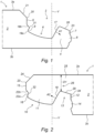
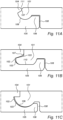
- FIG. 1 schematically shows a floor panel (1) according to the present invention, and shows the first coupling part (2) of the panel (1).
- the panel (1) comprises a centrally located core (3) provided with an upper side (3a) and a lower side (3b).
- the first coupling part (2) comprises an upward tongue (4), an upward flank (5), lying at a distance from the upward tongue (4) and an upward groove (6) formed in between the upward tongue (4) and the upward flank (6).
- the upward groove (6) is adapted to receive at least a part of a downward tongue of a second coupling part of an adjacent panel.
- a part of a side (7) of the upward tongue (4) facing away from the upward flank (5) is provided with a first locking element (8), in the form of an outward bulge (8), adapted for co-action with a second locking element of an adjacent floor panel.
- a part of the upward flank (5) is provided with a fourth locking element (9), in the form of a recess (9), adapted for co-action with the third locking element of an adjacent floor panel.
- a part of a side (17) of the upward tongue (4) facing toward the upward flank (5) is inclined with respect to a vertical direction (V) and is angled away from the upward flank (5), indicated with an arrow (A1).
- a part (19) of the upward flank (5) is curved (19a) or inclined (19b), wherein the fourth locking element (9) is located on the curved (19a) or inclined (19b) part.
- An upper part (20) of the upward flank (5) is provided with a bevel (21).
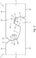
- FIG. 2 schematically shows a floor panel (1) according to the present invention, and shows the second coupling part (10) of the panel (1).
- the panel (1) comprises a centrally located core (3) provided with an upper side (3a) and a lower side (3b).
- the second coupling part (10) comprises a downward tongue (11), a downward flank (12) lying at a distance from the downward tongue (11), and a downward groove (13) formed in between the downward tongue (11) and the downward flank (12) wherein the downward groove (11) is adapted to receive at least a part of an upward tongue of a first coupling part of an adjacent panel.
- a part of a side of the downward flank (12) is provided with a second locking element (14), in the form of a recess (14), adapted for co-action with the first locking element of an adjacent floor panel.
- a part of a side (15) of the downward tongue (11) facing away from the downward flank (12) is provided with a third locking element (16), in the form of an outward bulge (16), adapted for co-action with a fourth locking element of an adjacent floor panel.
- a part of a side (18) of the downward tongue (11) facing toward the downward flank (12) is inclined with respect to a vertical direction (V) and is angled away from the downward flank (12), indicated with an arrow (A2).
- a part of the side (15) of the downward tongue (11) facing away from the downward flank (12) is curved (22a) or inclined (22b), wherein the third locking element (16) is located on the curved (22a) or inclined (22b) part.
- An upper part (23) of the side (15) of the downward tongue (11) facing away from the downward flank (12) is provided with a bevel (24).
- the third locking element (16) is located inward compared to the upper part (23) of the side (15) of the downward tongue (11) facing away from the downward flank (12).
- the upward flank (5) is also provided with a sixth locking element (31), in the form of a an outward bulge (31), adapted for co-action with the fifth locking element (32), in the form of a recess (32) of an adjacent floor panel (1).
- the fourth (9) and sixth (31) locking element are arranged directly below each other in figure 1 , and together form sort of an Z-shape, or S-shape or zigzag-shape.
- a part of a side (18) of the downward tongue (11) facing away from the downward flank (12) is provided with a fifth locking element (32), in the form of a recess (32), adapted for co-action with a sixth locking element (31), in the form of an outward bulge (31), of an adjacent floor panel (1).
- the third (16) and fifth (32) locking element are arranged directly below each other in figure 2 , and together form sort of an Z-shape, or S-shape or zigzag-shape.
- transition (34) between the downward flank (12) and the upper side (29) of the downward groove (13) defines a concave vertex (34).
- Figure 3 shows the first and second coupling parts of figures 1 and 2 in a coupled condition.
- a gap (27) is present between the upper side (28) of the upward tongue (4) and the upper side (29) of the downward groove (13), wherein the gap (27) widens from the side (17) of the upward tongue (4) facing towards the upward flank (5) to the downward flank (12).
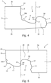
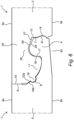
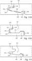
- Figures 4-6 show a variant to the panel shown in figures 1-3 .
- Figure 4 shows the first coupling part, figure 5 the second coupling part and figure 6 a coupled condition.
- figures 1-3 and 4-6 show a "closed groove” locking system. This is indicated by the arrows (A3 and A4), which show that the sides (17, 18) of the tongues (4, 11) are directed towards the flanks (5, 12), rather than away from the flanks (5, 12). Beneath the upward tongue (4), a space (30) is present, such that, when placed on the floor, a space (30) exists between the upward tongue (4) and the floor the panel is placed on.
- the "closed groove” embodiment is shown, the same, or at least similar, profile can be used in an "open groove” embodiment as well.
- Figures 7 and 8 show, in a coupled condition, the levels of the first and second locking elements (L1), the third and fourth locking elements (L3) and the highest point of the upward tongue (LH).
- the level of the third and fourth locking elements (L3) lies between the level of the highest point of the upward tongue (LH) and the level of the first and second locking elements (L1).
- Figure 7 also indicates the level of the lowest part of the bevel as (LB). Between that level (LB) and the level of the third and fourth locking elements (L3) a distance exists, such that the third and fourth locking elements are not visible through the bevel.
- the levels of the locking elements are showing the horizontal centrelines of the locking elements.
- the centreline (L4) of the fifth and sixth locking elements is indicated, which lies above a the centreline (L3) of the third locking element, above the centreline of the first locking element (L1) and below the level (L3) of the highest point of the upward tongue.
- the centreline (L3) of the third and/or fourth locking element coincides locally with the transition between the transition (33) between the side (7) of the upward tongue (4) facing away from the upward flank (5), and the upper side (28) of the upward tongue (4), which transition defines a convex vertex (33).
- the centreline (L3) of the third locking element is situated in between a centreline of the concave vertex (34) and the centreline (L1) of the first and/or second locking element.
- Figure 9 schematically shows the coupling of two panels as shown in figures 1-3 and 7 .
- Figure 10 schematically shows the uncoupling of two panels as shown in figures 1-3 and 7 .
- Figure 9 shows coupling by a vertical movement (indicated with the vertical arrow).
- step A the panels are moved towards each other.
- step B the first and second locking elements are engaging.
- step C a deformation of the bridge part of the second coupling part occurs, indicated with the curved arrow.
- step D the first and second locking elements are sliding in place, and the third and fourth locking elements are engaging.
- step E the coupling is complete.
- Figure 10 shows the coupled condition in step E.
- step F uncoupling is initiated by a rotation (large arrow), causing a deformation of the bridge part of the second coupling part (small arrow).
- step G the coupling is undone, wherein in step H both panels are free from each other, corresponding to step A of figure 9 .
- FIGS 11A-11J schematically show various alternative embodiments for coupling parts.
- the coupling parts as described in the previous figures are especially suitable for short sides of elongated panels. These coupling parts are typically on two opposite sides, or two opposite short sides, of such panels. On the other sides, for instance on two opposite long sides of such panels, angling down profiles could be present.
- Figures 11A-11J show various coupling parts which are suitable for using on these opposite sides of the panel.
- Each of these embodiments can be angled in place, by turning or rotating the sideward tongues (101) into sideward grooves (102).
- gaps (103) are present in coupled conditions, which can be used to accumulate foreign material such as dust.
- the sideward grooves (102) are typically bordered by an upper lip (104) and a lower lip (105) extending beyond the upper lip (104), wherein the upper lip (104) is provided with an upward shoulder (106), which cooperates with a groove typically underneath the sideward tongue (101).
- the entrance to the groove (102) is angled or chamfered (107).
- an intermediate space (108) may be present between the coupling elements, between the outside of the upward shoulder (106) and the core of the panel.
- the embodiments as shown in figures 11A , C, D and E have a rounded bottom (109) of the sideward tongue, and a corresponding rounded recess in the sideward groove, which rounding facilitates the angling of such panels.
- the embodiments of figures 11B , F, H and J rely on a relative flat bottom (110) and corresponding recess, which is easy to produces and increases vertical locking.
- the embodiments of figures 11A , F and J show the use of a bevel (111) on such angling down profiles.
- the embodiment of figure 11G shows an embodiment of an angling down profile wherein the sideward groove has a specific shape allowing it to force the sideward tongue into the sideward groove in a coupled condition.
- the embodiment of figure 11I shows a double structure, or a sandwich structure of both the sideward tongue and the sideward groove.
- Figures 12 and 13 show a variation on the panels with coupling parts of figures 1 and 2 . Corresponding features have been given the same reference numbers.
- the third locking element (16) is provided on the outside of the downward tongue (11), in the form of a bulge (16), and the fourth locking element (9) is provided on the upward flank (5), in the form of a recess (9).
- the upward flank (5) is provided with a third locking element (16) in the form of the bulge (16)
- the side of the downward tongue (11) facing away from the downward flank (12) is provided with a fourth locking element (9), in the form of a recess (9).
- inventive concepts are illustrated by several illustrative embodiments. It is conceivable that individual inventive concepts may be applied without, in so doing, also applying other details of the described example. It is not necessary to elaborate on examples of all conceivable combinations of the above-described inventive concepts, as a person skilled in the art will understand numerous inventive concepts can be (re)combined in order to arrive at a specific application.
- first locking element The panels according to the invention may also be referred to as tiles.
- complementary coupling profiles or locking elements is meant that these coupling profiles (or locking elements) can cooperate with each other.
- the complementary coupling profiles (or locking elements) do not necessarily have to have complementary forms. Expressions like “horizontal”, “vertical”, and “inclined” are relative expressions with respect to a panel being laid on a (virtual) horizontal supporting structure, like a subfloor.
- a plane defined by the panel is qualified as a horizontal plane.
- vertical direction is therefore meant locking in a direction perpendicular to the plane of the tile.
- horizontal direction is therefore meant locking in a direction perpendicular to the respective coupled edges of two tiles and parallel to or falling together with the plane defined by the tiles.
Landscapes
- Engineering & Computer Science (AREA)
- Architecture (AREA)
- Civil Engineering (AREA)
- Structural Engineering (AREA)
- Floor Finish (AREA)
- Particle Formation And Scattering Control In Inkjet Printers (AREA)
- Glass Compositions (AREA)
- Gas-Filled Discharge Tubes (AREA)
Claims (21)
- Panneau (1), en particulier panneau de plancher (1) ou panneau mural, comprenant :- un noyau placé de façon centrale (3) pourvu d'un côté supérieur (3a) et d'un côté inférieur (3b), lequel noyau (3) définit un plan ;- au moins une première partie de couplage (2) et au moins une deuxième partie de couplage (10) raccordées respectivement à des bords opposés du noyau (3),∘ laquelle première partie de couplage (2) comprend une languette montante (4), au moins un flanc montant (5) sis à une certaine distance de la languette montante (4) et une rainure montante (6) formée entre la languette montante (4) et le flanc montant (5), la rainure montante (6) étant conçue pour recevoir au moins une partie d'une languette descendante (11) d'une deuxième partie de couplage (10) d'un panneau adjacent (1) :∘ laquelle deuxième partie de couplage (10) comprend une languette descendante (11), au moins un flanc descendant (12) sis à une certaine distance de la languette descendante (11), et une rainure descendante (13) formée entre la languette descendante (11) et le flanc descendant (12), la rainure descendante (13) étant conçue pour recevoir au moins une partie d'une languette montante (4) d'une première partie de couplage (10) d'un panneau adjacent (1) ;- au moins une partie d'un côté (7) de la languette montante (4) tourné à l'écart du flanc montant (5) étant pourvue d'un premier élément de verrouillage (8), par exemple sous la forme d'un renflement vers l'extérieur (8) ou d'un évidement, conçu pour coopérer avec un deuxième élément de verrouillage (14), par exemple sous la forme d'un évidement ou d'un renflement vers l'extérieur, d'un panneau de plancher adjacent (1) ;- au moins une partie d'un côté du flanc descendant (12) étant pourvue d'un deuxième élément de verrouillage (14), par exemple sous la forme d'un évidement (14) ou d'un renflement vers l'extérieur, conçu pour coopérer avec le premier élément de verrouillage (8), par exemple sous la forme d'un renflement vers l'extérieur (8) ou d'un évidement, d'un panneau de plancher adjacent (1) ;- au moins une partie d'un côté (15) de la languette descendante (11) tourné à l'écart du flanc descendant (12) étant pourvue d'un troisième élément de verrouillage (16), par exemple sous la forme d'un renflement vers l'extérieur (16) ou d'un évidement, conçu pour coopérer avec un quatrième élément de verrouillage (9), par exemple sous la forme d'un évidement (9) ou d'un renflement vers l'extérieur, d'un panneau de plancher adjacent (1) ;- au moins une partie du flanc montant (5) étant pourvue d'un quatrième élément de verrouillage (9), par exemple sous la forme d'un évidement (9) ou d'un renflement vers l'extérieur, conçu pour coopérer avec le troisième élément de verrouillage (16), par exemple sous la forme d'un renflement vers l'extérieur (16) ou d'un évidement, d'un panneau de plancher adjacent (1),grâce à quoi le côté (17) de la languette montante (4) tourné vers le flanc montant (5) est incliné vers le haut dans une direction à l'écart du flanc montant (5), et grâce à quoi le côté (18) de la languette descendante (11) tourné vers le flanc descendant (12) est incliné vers le bas dans une direction à l'écart du flanc descendant (12), de telle sorte que, dans un état couplé de panneaux adjacents, le panneau soit configuré pour être découplé par rapport à un panneau adjacent à l'aide d'un mouvement angulaire,caractérisé en ce qu'une ligne centrale horizontale du troisième élément de verrouillage (16) et/ou une ligne centrale horizontale du quatrième élément de verrouillage (9) est/sont située(s) entre (i) une ligne centrale horizontale (L1) du premier élément de verrouillage (8) et/ou une ligne centrale horizontale (L1) du deuxième élément de verrouillage (14), et (ii) une ligne horizontale (LH) définissant la hauteur maximale de la languette montante (4).
- Panneau (1) selon la revendication 1, dans lequel au moins une partie d'un côté (15) de la languette descendante (11) tourné à l'écart du flanc descendant (12) est pourvue d'un cinquième élément de verrouillage (32), par exemple sous la forme d'un renflement vers l'extérieur ou d'un évidement (32), conçu pour coopérer avec un sixième élément de verrouillage (31), par exemple sous la forme d'un évidement ou d'un renflement vers l'extérieur (31), d'un panneau de plancher adjacent (1), et au moins une partie du flanc montant (5) est pourvue d'un sixième élément de verrouillage (31), par exemple sous la forme d'un évidement ou d'un renflement vers l'extérieur (31), conçu pour coopérer avec le cinquième élément de verrouillage (32), par exemple sous la forme d'un renflement vers l'extérieur ou d'un évidement (32), d'un panneau de plancher adjacent (1).
- Panneau (1) selon la revendication 2, dans lequel un élément de verrouillage du troisième élément de verrouillage (16) et du cinquième élément de verrouillage (9) est formé par un renflement et un autre élément de verrouillage du troisième élément de verrouillage (16) et du cinquième élément de verrouillage (9) est formé par un évidement, et/ou dans lequel un élément de verrouillage du quatrième élément de verrouillage (9) et du sixième élément de verrouillage (31) est formé par un renflement et un autre élément de verrouillage du quatrième élément de verrouillage (9) et du sixième élément de verrouillage (31) est formé par un évidement.
- Panneau (1) selon l'une des revendications 2 à 3, dans lequel le troisième élément de verrouillage (16) et le cinquième élément de verrouillage (32) ont des profils différents, et/ou dans lequel le quatrième élément de verrouillage (9) et le sixième élément de verrouillage (31) ont des profils différents.
- Panneau (1) selon l'une des revendications 2 à 4, dans lequel une ligne centrale du cinquième élément de verrouillage (32) et une ligne centrale du sixième élément de verrouillage (31) sont situées au-dessus d'une ligne centrale du troisième élément de verrouillage (16).
- Panneau (2) selon l'une des revendications 2 à 5, dans lequel une ligne centrale horizontale du cinquième élément de verrouillage (32) et/ou une ligne centrale horizontale du sixième élément de verrouillage (31) est/sont située(s) entre (i) la ligne centrale horizontale (L1) du premier élément de verrouillage (8) et (ii) la ligne horizontale (LH) définissant la hauteur maximale de la languette montante (4).
- Panneau (1) selon l'une des revendications précédentes, dans lequel la transition entre le côté (7) de la languette montante (4) tourné à l'écart du flanc montant (5), et le côté supérieur (28) de la languette montante (4), définit un sommet convexe (33), et dans lequel une ligne centrale du quatrième élément de verrouillage (9) coïncide substantiellement avec une ligne centrale dudit sommet convexe (33), le sommet convexe (33) étant préférablement défini par une transition entre une partie plate, préférablement orientée verticalement, du côté (7) de la languette montante (4) tourné à l'écart du flanc montant (5), et une partie plate, préférablement inclinée, du côté supérieur (28) de la languette montante (4).
- Panneau (1) selon l'une des revendications précédentes, dans lequel la transition entre le flanc descendant (12) et le côté supérieur (29) de la rainure descendante (13) définit un sommet concave (34), et dans lequel une ligne centrale du troisième élément de verrouillage (16) est située entre une ligne centrale dudit sommet concave (34) et une ligne centrale dudit deuxième élément de verrouillage (14), ou dans lequel une ligne centrale du troisième élément de verrouillage (16) coïncide substantiellement avec une ligne centrale dudit sommet concave (34).
- Panneau (1) selon l'une des revendications précédentes, dans lequel le côté supérieur substantiellement complet (28) de la languette montante (4) est plat, et le côté supérieur (28) de la languette montante (4) étant incliné vers le bas dans une direction à l'écart du flanc montant (5), et/ou dans lequel le côté supérieur (29) de la rainure descendante (13) est incliné vers le bas dans une direction vers le flanc descendant (12).
- Panneau (1) selon l'une des revendications précédentes, dans lequel le côté (7) de la languette montante (4) tourné à l'écart du flanc montant (5) comprend deux parties de côté substantiellement verticales, dans lequel le premier élément de verrouillage (8) est situé entre lesdites parties de côté substantiellement verticales.
- Panneau (1) selon l'une des revendications précédentes, dans lequel au moins une partie d'un côté (17) de la languette montante (4) tourné vers le flanc montant (5) est inclinée par rapport à une direction verticale (V) et est en angle vers le flanc montant (5) ;
et dans lequel au moins une partie d'un côté (18) de la languette descendante (11) tourné vers le flanc descendant (12) est inclinée par rapport à une direction verticale (V). - Panneau (1) selon l'une des revendications précédentes, dans lequel au moins une partie d'un côté (17) de la languette montante (4) tourné vers le flanc montant (5) est inclinée par rapport à une direction verticale (V) et est en angle à l'écart du flanc montant (5) ;
et dans lequel au moins une partie d'un côté (18) de la languette descendante (11) tourné vers le flanc descendant (12) est inclinée par rapport à une direction verticale (V). - Panneau (1) selon l'une quelconque des revendications précédentes, dans lequel la partie du côté (15) de la languette descendante (11) tourné à l'écart du flanc descendant (12) et/ou au moins une partie (19) du flanc montant (5) est/sont au moins partiellement incurvée(s) (22a, 19a) ou inclinée(s) (22b, 19b), le troisième (16) et/ou le quatrième élément(s) de verrouillage (9) étant placé(s) sur la partie au moins partiellement incurvée (22a, 19a) ou inclinée (22b, 19b).
- Panneau (1) selon l'une quelconque des revendications précédentes, dans lequel une partie supérieure (20) du flanc montant (5) et/ou une partie supérieure (23) du côté (15) de la languette descendante (11) tourné à l'écart du flanc descendant (12) est/sont pourvue(s) d'un biseau (21, 24), dans lequel, préférablement, les troisième (16) et quatrième (9) éléments de verrouillage sont placés à une certaine distance de la partie la plus basse (LB) du biseau (21, 24).
- Panneau (1) selon l'une quelconque des revendications précédentes, dans lequel le troisième élément de verrouillage (16) est placé vers l'intérieur comparé à une partie supérieure (23) du côté (15) de la languette descendante (11) tourné à l'écart du flanc descendant (12).
- Panneau (1) selon l'une quelconque des revendications précédentes, dans lequel les troisième (16) et quatrième (9) éléments de verrouillage sont agencés à un niveau supérieur comparé au niveau des premier et deuxième éléments de verrouillage (L1), et/ou dans lequel les troisième (16) et quatrième (9) éléments de verrouillage sont agencés à un niveau inférieur comparé au point le plus élevé de la languette montante (LH), dans lequel, préférablement, les troisième (16) et quatrième (9) éléments de verrouillage sont agencés, au moins dans une direction verticale, entre le point le plus haut de la languette montante (LH) et le niveau des premier et deuxième éléments de verrouillage (L1).
- Panneau (1) selon l'une quelconque des revendications précédentes, dans lequel les troisième (16) et quatrième (9) éléments de verrouillage sont conçus pour coopérer afin de fournir un verrouillage vertical et/ou dans lequel les premier (8) et deuxième (14) éléments de verrouillage sont conçus pour coopérer afin de fournir un verrouillage vertical.
- Panneau (1) selon l'une quelconque des revendications précédentes, dans lequel la deuxième partie de couplage (10) est configurée pour se déformer au moins temporairement pendant le couplage, en particulier la partie de pont (25) de la deuxième partie de couplage (10).
- Panneau (1) selon l'une quelconque des revendications précédentes, dans lequel le panneau (1), en particulier la première partie de couplage (2) du panneau, est configuré pour être couplé à un panneau adjacent, en particulier à la deuxième partie de couplage (10) du panneau, à l'aide d'un mouvement angulaire.
- Panneau (1) selon l'une quelconque des revendications précédentes, dans lequel, dans l'état couplé de panneaux adjacents, la deuxième partie de couplage du panneau est configurée pour être découplée par rapport à la première partie de couplage (2) d'un panneau adjacent (1) à l'aide d'un mouvement angulaire.
- Revêtement, en particulier revêtement de sol ou revêtement mural, comprenant une pluralité de panneaux raccordés entre eux (1) selon l'une quelconque des revendications précédentes, la première partie de couplage (2) d'un panneau coopérant avec la deuxième partie de couplage (10) d'un panneau adjacent, de telle sorte que les panneaux soient configurés pour être découplés à l'aide d'un mouvement angulaire.
Priority Applications (1)
| Application Number | Priority Date | Filing Date | Title |
|---|---|---|---|
| EP23184850.8A EP4245942A3 (fr) | 2018-01-09 | 2019-01-09 | Panneau |
Applications Claiming Priority (3)
| Application Number | Priority Date | Filing Date | Title |
|---|---|---|---|
| NL2020256A NL2020256B1 (en) | 2018-01-09 | 2018-01-09 | Panel |
| PCT/EP2019/050459 WO2019137964A1 (fr) | 2018-01-09 | 2019-01-09 | Panneau |
| EP19701035.8A EP3737804B1 (fr) | 2018-01-09 | 2019-01-09 | Panneau |
Related Parent Applications (1)
| Application Number | Title | Priority Date | Filing Date |
|---|---|---|---|
| EP19701035.8A Division EP3737804B1 (fr) | 2018-01-09 | 2019-01-09 | Panneau |
Related Child Applications (2)
| Application Number | Title | Priority Date | Filing Date |
|---|---|---|---|
| EP23184850.8A Division-Into EP4245942A3 (fr) | 2018-01-09 | 2019-01-09 | Panneau |
| EP23184850.8A Division EP4245942A3 (fr) | 2018-01-09 | 2019-01-09 | Panneau |
Publications (3)
| Publication Number | Publication Date |
|---|---|
| EP4043663A1 EP4043663A1 (fr) | 2022-08-17 |
| EP4043663B1 true EP4043663B1 (fr) | 2023-07-12 |
| EP4043663B8 EP4043663B8 (fr) | 2023-08-23 |
Family
ID=61628418
Family Applications (3)
| Application Number | Title | Priority Date | Filing Date |
|---|---|---|---|
| EP22164982.5A Active EP4043663B8 (fr) | 2018-01-09 | 2019-01-09 | Panneau |
| EP23184850.8A Pending EP4245942A3 (fr) | 2018-01-09 | 2019-01-09 | Panneau |
| EP19701035.8A Active EP3737804B1 (fr) | 2018-01-09 | 2019-01-09 | Panneau |
Family Applications After (2)
| Application Number | Title | Priority Date | Filing Date |
|---|---|---|---|
| EP23184850.8A Pending EP4245942A3 (fr) | 2018-01-09 | 2019-01-09 | Panneau |
| EP19701035.8A Active EP3737804B1 (fr) | 2018-01-09 | 2019-01-09 | Panneau |
Country Status (19)
| Country | Link |
|---|---|
| US (4) | US11377856B2 (fr) |
| EP (3) | EP4043663B8 (fr) |
| JP (1) | JP7350774B2 (fr) |
| KR (1) | KR102541894B1 (fr) |
| CN (1) | CN111566293B (fr) |
| AU (1) | AU2019207683B2 (fr) |
| CA (1) | CA3087641A1 (fr) |
| CL (1) | CL2020001792A1 (fr) |
| EA (1) | EA038612B1 (fr) |
| ES (1) | ES2911808T3 (fr) |
| HR (1) | HRP20220494T1 (fr) |
| HU (1) | HUE063540T2 (fr) |
| MA (1) | MA51561A (fr) |
| MY (1) | MY207963A (fr) |
| NL (1) | NL2020256B1 (fr) |
| PL (2) | PL3737804T3 (fr) |
| UA (1) | UA125984C2 (fr) |
| WO (1) | WO2019137964A1 (fr) |
| ZA (1) | ZA202003707B (fr) |
Families Citing this family (25)
| Publication number | Priority date | Publication date | Assignee | Title |
|---|---|---|---|---|
| EP4092213B1 (fr) * | 2010-01-11 | 2023-12-13 | Välinge Innovation AB | Revêtement de sol avec conception d'interverrouillage |
| NL2020256B1 (en) | 2018-01-09 | 2019-07-15 | Innovations4Flooring Holding N V | Panel |
| NL2021886B1 (en) * | 2018-10-26 | 2020-05-13 | I4F Licensing Nv | Panel, in particular a floor panel or wall panel, and panel covering |
| NL2021884B1 (en) | 2018-10-26 | 2020-05-13 | I4F Licensing Nv | Panel, in particular a floor panel or wall panel |
| WO2020159355A1 (fr) * | 2019-01-30 | 2020-08-06 | Floor Locking Technology B.V. | Panneau et revêtement le comprenant |
| EP3798386A1 (fr) * | 2019-09-24 | 2021-03-31 | Välinge Innovation AB | Ensemble de panneaux avec bords verrouillables mécaniquement |
| NL2024192B1 (en) * | 2019-11-08 | 2021-07-28 | I4F Licensing Nv | Decorative panel, and decorative floor covering consisting of said panels |
| NL2024193B1 (en) * | 2019-11-08 | 2021-07-20 | I4F Licensing Nv | Decorative panel suitable for assembling a floor, ceiling or wall covering by interconnecting a plurality of said panels with each other, and decorative covering of such interconnected panels |
| NL2024191B1 (en) * | 2019-11-08 | 2021-07-20 | I4F Licensing Nv | Panel, in particular a floor panel or a wall panel |
| EP4560089A3 (fr) | 2019-12-03 | 2025-11-05 | Unilin, BV | Panneau de plancher pour former un revêtement de sol |
| SE544438C2 (en) | 2019-12-13 | 2022-05-31 | Vilox Ab | Releasable joining system for floor panels, a floor panel, a floor system, a method for laying and a method for releasing a floor panel |
| EP4545731A3 (fr) * | 2020-02-07 | 2025-07-02 | Unilin, BV | Panneau de plancher ou de mur |
| BE1028185B1 (nl) * | 2020-04-03 | 2021-11-04 | Flooring Ind Ltd Sarl | Paneel |
| US12030290B2 (en) * | 2020-06-12 | 2024-07-09 | Välinge Innovation AB | Building panel comprising mineral-based layer |
| US12392140B2 (en) | 2020-07-31 | 2025-08-19 | I4F Licensing Nv | Panel and covering |
| NL2026190B1 (en) * | 2020-07-31 | 2022-04-04 | I4F Licensing Nv | Panel and covering |
| NL2026191B1 (en) * | 2020-07-31 | 2022-04-04 | I4F Licensing Nv | Panel and covering |
| PT4189192T (pt) | 2020-07-31 | 2025-03-10 | I4F Licensing Nv | Painel e revestimento |
| EP3971364A1 (fr) * | 2020-09-17 | 2022-03-23 | Surface Technologies GmbH & Co. KG | Panneau |
| NL2026581B1 (en) * | 2020-09-30 | 2022-06-01 | I4F Licensing Nv | Panel, covering, and method for manufacturing such a panel |
| NL2026858B1 (en) | 2020-11-09 | 2022-06-27 | I4F Licensing Nv | Decorative panel, and covering of such decorative panels |
| US11814838B2 (en) * | 2021-07-02 | 2023-11-14 | I4F Licensing Nv | Wall panel for forming a wall covering with multiple panels |
| NL2028776B1 (en) * | 2021-07-19 | 2023-01-25 | I4F Licensing Nv | Multi-purpose tile system, tile covering, and tile |
| CN113833228B (zh) * | 2021-09-29 | 2023-03-10 | 中山市大自然格瑞新型材料有限公司 | 一种地板锁扣及地板 |
| US12571216B1 (en) * | 2024-11-22 | 2026-03-10 | Westlake Royal Building Products (Usa) Inc. | Interlocking panels with v-shaped seams |
Family Cites Families (30)
| Publication number | Priority date | Publication date | Assignee | Title |
|---|---|---|---|---|
| US7896571B1 (en) | 1999-06-30 | 2011-03-01 | Akzenta Paneele + Profile Gmbh | Panel and panel fastening system |
| DE50309830D1 (de) * | 2002-11-15 | 2008-06-26 | Flooring Technologies Ltd | Einrichtung bestehend aus zwei miteinander verbindbaren Bauplatten und einem Einsatz zum Verriegeln dieser Bauplatten |
| KR100566083B1 (ko) * | 2003-08-07 | 2006-03-30 | 주식회사 한솔홈데코 | 조립식 바닥재 |
| DE102005059540A1 (de) * | 2005-08-19 | 2007-06-14 | Bauer, Jörg R. | Lösbar aneinander zu befestigende, flächige Bauteile, sowie Bauteil |
| DK2009197T3 (en) * | 2006-04-14 | 2016-06-13 | Yekalon Ind Inc | Floor block, floor system and laying method therefore |
| CN101845879B (zh) * | 2006-04-14 | 2014-04-09 | 深圳市燕加隆实业发展有限公司 | 地板块、地板系统及铺设地板系统的方法 |
| BE1017403A5 (nl) * | 2006-12-21 | 2008-08-05 | Flooring Ind Ltd | Vloerelement, vergrendelingsysteem voor vloerelementen, vloerbekleding en werkwijze voor het samenstellen van dergelijke vloerelementen tot een vloerbekleding. |
| NL2003019C2 (nl) * | 2009-06-12 | 2010-12-15 | 4Sight Innovation Bv | Vloerpaneel en vloerbedekking bestaande uit meerdere van dergelijke vloerpanelen. |
| DE202011110452U1 (de) * | 2011-01-28 | 2014-02-11 | Akzenta Paneele + Profile Gmbh | Paneel |
| US8806832B2 (en) * | 2011-03-18 | 2014-08-19 | Inotec Global Limited | Vertical joint system and associated surface covering system |
| SG193535A1 (en) * | 2011-03-18 | 2013-10-30 | Inotec Internat Pty Ltd | Vertical joint system and associated surface covering system |
| KR102069909B1 (ko) * | 2012-02-07 | 2020-01-23 | 플로어링 인더스트리즈 리미티드 에스에이알엘 | 플로어 커버링을 형성하기 위한 플로어 패널, 그러한 플로어 패널들로부터 형성된 플로어 커버링 및 그러한 플로어 패널들의 제작 방법 |
| CN110043001A (zh) * | 2014-02-26 | 2019-07-23 | 创新四号地板控股有限公司 | 可与类似的镶板互连来形成覆盖装置的镶板 |
| FR3024990B1 (fr) * | 2014-08-25 | 2018-11-16 | Gerflor | Panneau de sol pour la realisation d'un revetement. |
| US10316526B2 (en) | 2014-08-29 | 2019-06-11 | Valinge Innovation Ab | Vertical joint system for a surface covering panel |
| NO3031998T3 (fr) * | 2014-12-08 | 2018-02-24 | ||
| BE1023545B1 (nl) * | 2015-10-23 | 2017-04-28 | Flooring Industries Limited, Sarl | Set van vloerpanelen voor het vormen van een vloerbekleding |
| US10648182B2 (en) * | 2015-12-31 | 2020-05-12 | Flooring Industries Limited, Sarl | Floor panel for forming a floor covering |
| NL2018970B1 (en) * | 2017-05-23 | 2018-12-04 | Innovations 4 Flooring Holding Nv | Multi-purpose tile system |
| NL2020256B1 (en) * | 2018-01-09 | 2019-07-15 | Innovations4Flooring Holding N V | Panel |
| NL2021886B1 (en) * | 2018-10-26 | 2020-05-13 | I4F Licensing Nv | Panel, in particular a floor panel or wall panel, and panel covering |
| NL2021885B1 (en) * | 2018-10-26 | 2020-05-13 | I4F Licensing Nv | Multi-purpose tile system, tile covering, and tile |
| NL2021884B1 (en) * | 2018-10-26 | 2020-05-13 | I4F Licensing Nv | Panel, in particular a floor panel or wall panel |
| NL2022114B1 (en) * | 2018-12-03 | 2020-06-30 | I4F Licensing Nv | Decorative panel, and decorative floor covering consisting of said panels |
| US10661141B1 (en) * | 2019-02-27 | 2020-05-26 | Athletic Technologies LLC | Tackling apparatus |
| NL2024630B1 (en) * | 2020-01-09 | 2021-09-07 | I4F Licensing Nv | Glue-down decorative floor covering system |
| WO2021245261A1 (fr) * | 2020-06-04 | 2021-12-09 | I4F Licensing Nv | Panneau décoratif et revêtement de sol décoratif constitué de ces panneaux |
| CN115698450A (zh) * | 2020-06-12 | 2023-02-03 | 瓦林格创新股份有限公司 | 包括基于矿物的层的建筑镶板 |
| US12392140B2 (en) * | 2020-07-31 | 2025-08-19 | I4F Licensing Nv | Panel and covering |
| NL2036705B1 (en) * | 2023-12-28 | 2025-07-11 | I4F Licensing Nv | Floor board and method for manufacturing such floor board |
-
2018
- 2018-01-09 NL NL2020256A patent/NL2020256B1/nl active
-
2019
- 2019-01-09 EP EP22164982.5A patent/EP4043663B8/fr active Active
- 2019-01-09 EA EA202091649A patent/EA038612B1/ru unknown
- 2019-01-09 UA UAA202004955A patent/UA125984C2/uk unknown
- 2019-01-09 US US16/960,602 patent/US11377856B2/en active Active
- 2019-01-09 PL PL19701035T patent/PL3737804T3/pl unknown
- 2019-01-09 JP JP2020556998A patent/JP7350774B2/ja active Active
- 2019-01-09 MY MYPI2020003273A patent/MY207963A/en unknown
- 2019-01-09 AU AU2019207683A patent/AU2019207683B2/en active Active
- 2019-01-09 MA MA051561A patent/MA51561A/fr unknown
- 2019-01-09 CN CN201980007595.4A patent/CN111566293B/zh active Active
- 2019-01-09 HU HUE22164982A patent/HUE063540T2/hu unknown
- 2019-01-09 HR HRP20220494TT patent/HRP20220494T1/hr unknown
- 2019-01-09 PL PL22164982.5T patent/PL4043663T3/pl unknown
- 2019-01-09 ES ES19701035T patent/ES2911808T3/es active Active
- 2019-01-09 CA CA3087641A patent/CA3087641A1/fr active Pending
- 2019-01-09 EP EP23184850.8A patent/EP4245942A3/fr active Pending
- 2019-01-09 WO PCT/EP2019/050459 patent/WO2019137964A1/fr not_active Ceased
- 2019-01-09 KR KR1020207020520A patent/KR102541894B1/ko active Active
- 2019-01-09 EP EP19701035.8A patent/EP3737804B1/fr active Active
-
2020
- 2020-06-19 ZA ZA2020/03707A patent/ZA202003707B/en unknown
- 2020-07-03 CL CL2020001792A patent/CL2020001792A1/es unknown
-
2022
- 2022-06-17 US US17/843,538 patent/US12158011B2/en active Active
-
2024
- 2024-11-08 US US18/941,879 patent/US12366071B2/en active Active
-
2025
- 2025-06-25 US US19/249,249 patent/US20250341099A1/en active Pending
Also Published As
Similar Documents
| Publication | Publication Date | Title |
|---|---|---|
| EP4043663B1 (fr) | Panneau | |
| US11913236B2 (en) | Mechanical locking system for floor panels | |
| US11441319B2 (en) | Panel and covering | |
| EP3684987B1 (fr) | Panneau et revêtement | |
| WO2019137965A1 (fr) | Panneau, en particulier panneau de plancher ou panneau mural | |
| HK40027213B (en) | Panel | |
| HK40027213A (en) | Panel | |
| CA3060635C (fr) | Panneau et revetement | |
| BR112020013952B1 (pt) | Painel | |
| NZ758601B2 (en) | Panel and covering |
Legal Events
| Date | Code | Title | Description |
|---|---|---|---|
| PUAI | Public reference made under article 153(3) epc to a published international application that has entered the european phase |
Free format text: ORIGINAL CODE: 0009012 |
|
| STAA | Information on the status of an ep patent application or granted ep patent |
Free format text: STATUS: REQUEST FOR EXAMINATION WAS MADE |
|
| STAA | Information on the status of an ep patent application or granted ep patent |
Free format text: STATUS: EXAMINATION IS IN PROGRESS |
|
| 17P | Request for examination filed |
Effective date: 20220331 |
|
| AC | Divisional application: reference to earlier application |
Ref document number: 3737804 Country of ref document: EP Kind code of ref document: P |
|
| AK | Designated contracting states |
Kind code of ref document: A1 Designated state(s): AL AT BE BG CH CY CZ DE DK EE ES FI FR GB GR HR HU IE IS IT LI LT LU LV MC MK MT NL NO PL PT RO RS SE SI SK SM TR |
|
| 17Q | First examination report despatched |
Effective date: 20220727 |
|
| RBV | Designated contracting states (corrected) |
Designated state(s): AL AT BE BG CH CY CZ DE DK EE ES FI FR GB GR HR HU IE IS IT LI LT LU LV MC MK MT NL NO PL PT RO RS SE SI SK SM TR |
|
| INTG | Intention to grant announced |
Effective date: 20230130 |
|
| STAA | Information on the status of an ep patent application or granted ep patent |
Free format text: STATUS: GRANT OF PATENT IS INTENDED |
|
| GRAS | Grant fee paid |
Free format text: ORIGINAL CODE: EPIDOSNIGR3 |
|
| GRAA | (expected) grant |
Free format text: ORIGINAL CODE: 0009210 |
|
| STAA | Information on the status of an ep patent application or granted ep patent |
Free format text: STATUS: THE PATENT HAS BEEN GRANTED |
|
| P01 | Opt-out of the competence of the unified patent court (upc) registered |
Effective date: 20230519 |
|
| AC | Divisional application: reference to earlier application |
Ref document number: 3737804 Country of ref document: EP Kind code of ref document: P |
|
| AK | Designated contracting states |
Kind code of ref document: B1 Designated state(s): AL AT BE BG CH CY CZ DE DK EE ES FI FR GB GR HR HU IE IS IT LI LT LU LV MC MK MT NL NO PL PT RO RS SE SI SK SM TR |
|
| RAP3 | Party data changed (applicant data changed or rights of an application transferred) |
Owner name: I4F LICENSING NV |
|
| REG | Reference to a national code |
Ref country code: CH Ref legal event code: EP |
|
| REG | Reference to a national code |
Ref country code: CH Ref legal event code: PK Free format text: BERICHTIGUNG B8 |
|
| REG | Reference to a national code |
Ref country code: IE Ref legal event code: FG4D |
|
| REG | Reference to a national code |
Ref country code: DE Ref legal event code: R096 Ref document number: 602019032840 Country of ref document: DE |
|
| RAV | Requested validation state of the european patent: fee paid |
Extension state: KH Effective date: 20230217 |
|
| REG | Reference to a national code |
Ref country code: NL Ref legal event code: FP |
|
| REG | Reference to a national code |
Ref country code: SE Ref legal event code: TRGR |
|
| REG | Reference to a national code |
Ref country code: LT Ref legal event code: MG9D |
|
| REG | Reference to a national code |
Ref country code: AT Ref legal event code: MK05 Ref document number: 1587292 Country of ref document: AT Kind code of ref document: T Effective date: 20230712 |
|
| PG25 | Lapsed in a contracting state [announced via postgrant information from national office to epo] |
Ref country code: GR Free format text: LAPSE BECAUSE OF FAILURE TO SUBMIT A TRANSLATION OF THE DESCRIPTION OR TO PAY THE FEE WITHIN THE PRESCRIBED TIME-LIMIT Effective date: 20231013 |
|
| PG25 | Lapsed in a contracting state [announced via postgrant information from national office to epo] |
Ref country code: ES Free format text: LAPSE BECAUSE OF FAILURE TO SUBMIT A TRANSLATION OF THE DESCRIPTION OR TO PAY THE FEE WITHIN THE PRESCRIBED TIME-LIMIT Effective date: 20230712 |
|
| PG25 | Lapsed in a contracting state [announced via postgrant information from national office to epo] |
Ref country code: IS Free format text: LAPSE BECAUSE OF FAILURE TO SUBMIT A TRANSLATION OF THE DESCRIPTION OR TO PAY THE FEE WITHIN THE PRESCRIBED TIME-LIMIT Effective date: 20231112 |
|
| REG | Reference to a national code |
Ref country code: HU Ref legal event code: AG4A Ref document number: E063540 Country of ref document: HU |
|
| PG25 | Lapsed in a contracting state [announced via postgrant information from national office to epo] |
Ref country code: RS Free format text: LAPSE BECAUSE OF FAILURE TO SUBMIT A TRANSLATION OF THE DESCRIPTION OR TO PAY THE FEE WITHIN THE PRESCRIBED TIME-LIMIT Effective date: 20230712 Ref country code: PT Free format text: LAPSE BECAUSE OF FAILURE TO SUBMIT A TRANSLATION OF THE DESCRIPTION OR TO PAY THE FEE WITHIN THE PRESCRIBED TIME-LIMIT Effective date: 20231113 Ref country code: NO Free format text: LAPSE BECAUSE OF FAILURE TO SUBMIT A TRANSLATION OF THE DESCRIPTION OR TO PAY THE FEE WITHIN THE PRESCRIBED TIME-LIMIT Effective date: 20231012 Ref country code: LV Free format text: LAPSE BECAUSE OF FAILURE TO SUBMIT A TRANSLATION OF THE DESCRIPTION OR TO PAY THE FEE WITHIN THE PRESCRIBED TIME-LIMIT Effective date: 20230712 Ref country code: LT Free format text: LAPSE BECAUSE OF FAILURE TO SUBMIT A TRANSLATION OF THE DESCRIPTION OR TO PAY THE FEE WITHIN THE PRESCRIBED TIME-LIMIT Effective date: 20230712 Ref country code: IS Free format text: LAPSE BECAUSE OF FAILURE TO SUBMIT A TRANSLATION OF THE DESCRIPTION OR TO PAY THE FEE WITHIN THE PRESCRIBED TIME-LIMIT Effective date: 20231112 Ref country code: HR Free format text: LAPSE BECAUSE OF FAILURE TO SUBMIT A TRANSLATION OF THE DESCRIPTION OR TO PAY THE FEE WITHIN THE PRESCRIBED TIME-LIMIT Effective date: 20230712 Ref country code: GR Free format text: LAPSE BECAUSE OF FAILURE TO SUBMIT A TRANSLATION OF THE DESCRIPTION OR TO PAY THE FEE WITHIN THE PRESCRIBED TIME-LIMIT Effective date: 20231013 Ref country code: FI Free format text: LAPSE BECAUSE OF FAILURE TO SUBMIT A TRANSLATION OF THE DESCRIPTION OR TO PAY THE FEE WITHIN THE PRESCRIBED TIME-LIMIT Effective date: 20230712 Ref country code: ES Free format text: LAPSE BECAUSE OF FAILURE TO SUBMIT A TRANSLATION OF THE DESCRIPTION OR TO PAY THE FEE WITHIN THE PRESCRIBED TIME-LIMIT Effective date: 20230712 Ref country code: AT Free format text: LAPSE BECAUSE OF FAILURE TO SUBMIT A TRANSLATION OF THE DESCRIPTION OR TO PAY THE FEE WITHIN THE PRESCRIBED TIME-LIMIT Effective date: 20230712 |
|
| REG | Reference to a national code |
Ref country code: DE Ref legal event code: R097 Ref document number: 602019032840 Country of ref document: DE |
|
| PG25 | Lapsed in a contracting state [announced via postgrant information from national office to epo] |
Ref country code: SM Free format text: LAPSE BECAUSE OF FAILURE TO SUBMIT A TRANSLATION OF THE DESCRIPTION OR TO PAY THE FEE WITHIN THE PRESCRIBED TIME-LIMIT Effective date: 20230712 Ref country code: RO Free format text: LAPSE BECAUSE OF FAILURE TO SUBMIT A TRANSLATION OF THE DESCRIPTION OR TO PAY THE FEE WITHIN THE PRESCRIBED TIME-LIMIT Effective date: 20230712 Ref country code: EE Free format text: LAPSE BECAUSE OF FAILURE TO SUBMIT A TRANSLATION OF THE DESCRIPTION OR TO PAY THE FEE WITHIN THE PRESCRIBED TIME-LIMIT Effective date: 20230712 Ref country code: DK Free format text: LAPSE BECAUSE OF FAILURE TO SUBMIT A TRANSLATION OF THE DESCRIPTION OR TO PAY THE FEE WITHIN THE PRESCRIBED TIME-LIMIT Effective date: 20230712 Ref country code: CZ Free format text: LAPSE BECAUSE OF FAILURE TO SUBMIT A TRANSLATION OF THE DESCRIPTION OR TO PAY THE FEE WITHIN THE PRESCRIBED TIME-LIMIT Effective date: 20230712 Ref country code: SK Free format text: LAPSE BECAUSE OF FAILURE TO SUBMIT A TRANSLATION OF THE DESCRIPTION OR TO PAY THE FEE WITHIN THE PRESCRIBED TIME-LIMIT Effective date: 20230712 |
|
| PLBE | No opposition filed within time limit |
Free format text: ORIGINAL CODE: 0009261 |
|
| STAA | Information on the status of an ep patent application or granted ep patent |
Free format text: STATUS: NO OPPOSITION FILED WITHIN TIME LIMIT |
|
| PG25 | Lapsed in a contracting state [announced via postgrant information from national office to epo] |
Ref country code: IT Free format text: LAPSE BECAUSE OF FAILURE TO SUBMIT A TRANSLATION OF THE DESCRIPTION OR TO PAY THE FEE WITHIN THE PRESCRIBED TIME-LIMIT Effective date: 20230712 |
|
| 26N | No opposition filed |
Effective date: 20240415 |
|
| PG25 | Lapsed in a contracting state [announced via postgrant information from national office to epo] |
Ref country code: SI Free format text: LAPSE BECAUSE OF FAILURE TO SUBMIT A TRANSLATION OF THE DESCRIPTION OR TO PAY THE FEE WITHIN THE PRESCRIBED TIME-LIMIT Effective date: 20230712 |
|
| PG25 | Lapsed in a contracting state [announced via postgrant information from national office to epo] |
Ref country code: MC Free format text: LAPSE BECAUSE OF FAILURE TO SUBMIT A TRANSLATION OF THE DESCRIPTION OR TO PAY THE FEE WITHIN THE PRESCRIBED TIME-LIMIT Effective date: 20230712 |
|
| PG25 | Lapsed in a contracting state [announced via postgrant information from national office to epo] |
Ref country code: MC Free format text: LAPSE BECAUSE OF FAILURE TO SUBMIT A TRANSLATION OF THE DESCRIPTION OR TO PAY THE FEE WITHIN THE PRESCRIBED TIME-LIMIT Effective date: 20230712 |
|
| PG25 | Lapsed in a contracting state [announced via postgrant information from national office to epo] |
Ref country code: LU Free format text: LAPSE BECAUSE OF NON-PAYMENT OF DUE FEES Effective date: 20240109 |
|
| PG25 | Lapsed in a contracting state [announced via postgrant information from national office to epo] |
Ref country code: LU Free format text: LAPSE BECAUSE OF NON-PAYMENT OF DUE FEES Effective date: 20240109 |
|
| PG25 | Lapsed in a contracting state [announced via postgrant information from national office to epo] |
Ref country code: BG Free format text: LAPSE BECAUSE OF FAILURE TO SUBMIT A TRANSLATION OF THE DESCRIPTION OR TO PAY THE FEE WITHIN THE PRESCRIBED TIME-LIMIT Effective date: 20230712 |
|
| PG25 | Lapsed in a contracting state [announced via postgrant information from national office to epo] |
Ref country code: BG Free format text: LAPSE BECAUSE OF FAILURE TO SUBMIT A TRANSLATION OF THE DESCRIPTION OR TO PAY THE FEE WITHIN THE PRESCRIBED TIME-LIMIT Effective date: 20230712 |
|
| PG25 | Lapsed in a contracting state [announced via postgrant information from national office to epo] |
Ref country code: IE Free format text: LAPSE BECAUSE OF NON-PAYMENT OF DUE FEES Effective date: 20240109 |
|
| PG25 | Lapsed in a contracting state [announced via postgrant information from national office to epo] |
Ref country code: IE Free format text: LAPSE BECAUSE OF NON-PAYMENT OF DUE FEES Effective date: 20240109 |
|
| PGFP | Annual fee paid to national office [announced via postgrant information from national office to epo] |
Ref country code: CH Payment date: 20250201 Year of fee payment: 7 |
|
| PG25 | Lapsed in a contracting state [announced via postgrant information from national office to epo] |
Ref country code: CY Free format text: LAPSE BECAUSE OF FAILURE TO SUBMIT A TRANSLATION OF THE DESCRIPTION OR TO PAY THE FEE WITHIN THE PRESCRIBED TIME-LIMIT; INVALID AB INITIO Effective date: 20190109 |
|
| PGFP | Annual fee paid to national office [announced via postgrant information from national office to epo] |
Ref country code: PL Payment date: 20251219 Year of fee payment: 8 |
|
| REG | Reference to a national code |
Ref country code: CH Ref legal event code: U11 Free format text: ST27 STATUS EVENT CODE: U-0-0-U10-U11 (AS PROVIDED BY THE NATIONAL OFFICE) Effective date: 20260201 |
|
| PGFP | Annual fee paid to national office [announced via postgrant information from national office to epo] |
Ref country code: NL Payment date: 20260126 Year of fee payment: 8 |
|
| PGFP | Annual fee paid to national office [announced via postgrant information from national office to epo] |
Ref country code: HU Payment date: 20251223 Year of fee payment: 8 |
|
| PGFP | Annual fee paid to national office [announced via postgrant information from national office to epo] |
Ref country code: SE Payment date: 20260127 Year of fee payment: 8 |
|
| PGFP | Annual fee paid to national office [announced via postgrant information from national office to epo] |
Ref country code: GB Payment date: 20260127 Year of fee payment: 8 |
|
| PGFP | Annual fee paid to national office [announced via postgrant information from national office to epo] |
Ref country code: DE Payment date: 20260128 Year of fee payment: 8 |
|
| PGFP | Annual fee paid to national office [announced via postgrant information from national office to epo] |
Ref country code: BE Payment date: 20260127 Year of fee payment: 8 |
|
| PGFP | Annual fee paid to national office [announced via postgrant information from national office to epo] |
Ref country code: FR Payment date: 20260126 Year of fee payment: 8 |
|
| PGFP | Annual fee paid to national office [announced via postgrant information from national office to epo] |
Ref country code: TR Payment date: 20260108 Year of fee payment: 8 |