EP4043742A1 - Ensemble palier - Google Patents
Ensemble palier Download PDFInfo
- Publication number
- EP4043742A1 EP4043742A1 EP21157288.8A EP21157288A EP4043742A1 EP 4043742 A1 EP4043742 A1 EP 4043742A1 EP 21157288 A EP21157288 A EP 21157288A EP 4043742 A1 EP4043742 A1 EP 4043742A1
- Authority
- EP
- European Patent Office
- Prior art keywords
- bearing
- jewels
- arrangement
- gap
- jewel
- Prior art date
- Legal status (The legal status is an assumption and is not a legal conclusion. Google has not performed a legal analysis and makes no representation as to the accuracy of the status listed.)
- Withdrawn
Links
- 239000010437 gem Substances 0.000 claims abstract description 72
- 229910001751 gemstone Inorganic materials 0.000 claims abstract description 31
- 230000001050 lubricating effect Effects 0.000 claims abstract description 12
- 239000004575 stone Substances 0.000 claims description 12
- 238000006073 displacement reaction Methods 0.000 claims description 6
- 230000000295 complement effect Effects 0.000 claims description 4
- 238000011161 development Methods 0.000 description 7
- 230000018109 developmental process Effects 0.000 description 7
- 230000000694 effects Effects 0.000 description 5
- 238000007792 addition Methods 0.000 description 1
- 230000006835 compression Effects 0.000 description 1
- 238000007906 compression Methods 0.000 description 1
- 238000013016 damping Methods 0.000 description 1
- 230000001419 dependent effect Effects 0.000 description 1
- 230000002996 emotional effect Effects 0.000 description 1
- 239000000463 material Substances 0.000 description 1
- 238000007493 shaping process Methods 0.000 description 1
- 125000006850 spacer group Chemical group 0.000 description 1
Images



Classifications
-
- F—MECHANICAL ENGINEERING; LIGHTING; HEATING; WEAPONS; BLASTING
- F16—ENGINEERING ELEMENTS AND UNITS; GENERAL MEASURES FOR PRODUCING AND MAINTAINING EFFECTIVE FUNCTIONING OF MACHINES OR INSTALLATIONS; THERMAL INSULATION IN GENERAL
- F16C—SHAFTS; FLEXIBLE SHAFTS; ELEMENTS OR CRANKSHAFT MECHANISMS; ROTARY BODIES OTHER THAN GEARING ELEMENTS; BEARINGS
- F16C17/00—Sliding-contact bearings for exclusively rotary movement
- F16C17/02—Sliding-contact bearings for exclusively rotary movement for radial load only
-
- F—MECHANICAL ENGINEERING; LIGHTING; HEATING; WEAPONS; BLASTING
- F16—ENGINEERING ELEMENTS AND UNITS; GENERAL MEASURES FOR PRODUCING AND MAINTAINING EFFECTIVE FUNCTIONING OF MACHINES OR INSTALLATIONS; THERMAL INSULATION IN GENERAL
- F16C—SHAFTS; FLEXIBLE SHAFTS; ELEMENTS OR CRANKSHAFT MECHANISMS; ROTARY BODIES OTHER THAN GEARING ELEMENTS; BEARINGS
- F16C17/00—Sliding-contact bearings for exclusively rotary movement
- F16C17/02—Sliding-contact bearings for exclusively rotary movement for radial load only
- F16C17/03—Sliding-contact bearings for exclusively rotary movement for radial load only with tiltably-supported segments, e.g. Michell bearings
-
- F—MECHANICAL ENGINEERING; LIGHTING; HEATING; WEAPONS; BLASTING
- F16—ENGINEERING ELEMENTS AND UNITS; GENERAL MEASURES FOR PRODUCING AND MAINTAINING EFFECTIVE FUNCTIONING OF MACHINES OR INSTALLATIONS; THERMAL INSULATION IN GENERAL
- F16C—SHAFTS; FLEXIBLE SHAFTS; ELEMENTS OR CRANKSHAFT MECHANISMS; ROTARY BODIES OTHER THAN GEARING ELEMENTS; BEARINGS
- F16C17/00—Sliding-contact bearings for exclusively rotary movement
- F16C17/04—Sliding-contact bearings for exclusively rotary movement for axial load only
-
- F—MECHANICAL ENGINEERING; LIGHTING; HEATING; WEAPONS; BLASTING
- F16—ENGINEERING ELEMENTS AND UNITS; GENERAL MEASURES FOR PRODUCING AND MAINTAINING EFFECTIVE FUNCTIONING OF MACHINES OR INSTALLATIONS; THERMAL INSULATION IN GENERAL
- F16C—SHAFTS; FLEXIBLE SHAFTS; ELEMENTS OR CRANKSHAFT MECHANISMS; ROTARY BODIES OTHER THAN GEARING ELEMENTS; BEARINGS
- F16C17/00—Sliding-contact bearings for exclusively rotary movement
- F16C17/04—Sliding-contact bearings for exclusively rotary movement for axial load only
- F16C17/06—Sliding-contact bearings for exclusively rotary movement for axial load only with tiltably-supported segments, e.g. Michell bearings
-
- F—MECHANICAL ENGINEERING; LIGHTING; HEATING; WEAPONS; BLASTING
- F16—ENGINEERING ELEMENTS AND UNITS; GENERAL MEASURES FOR PRODUCING AND MAINTAINING EFFECTIVE FUNCTIONING OF MACHINES OR INSTALLATIONS; THERMAL INSULATION IN GENERAL
- F16C—SHAFTS; FLEXIBLE SHAFTS; ELEMENTS OR CRANKSHAFT MECHANISMS; ROTARY BODIES OTHER THAN GEARING ELEMENTS; BEARINGS
- F16C17/00—Sliding-contact bearings for exclusively rotary movement
- F16C17/12—Sliding-contact bearings for exclusively rotary movement characterised by features not related to the direction of the load
- F16C17/18—Sliding-contact bearings for exclusively rotary movement characterised by features not related to the direction of the load with floating brasses or brushing, rotatable at a reduced speed
-
- F—MECHANICAL ENGINEERING; LIGHTING; HEATING; WEAPONS; BLASTING
- F16—ENGINEERING ELEMENTS AND UNITS; GENERAL MEASURES FOR PRODUCING AND MAINTAINING EFFECTIVE FUNCTIONING OF MACHINES OR INSTALLATIONS; THERMAL INSULATION IN GENERAL
- F16C—SHAFTS; FLEXIBLE SHAFTS; ELEMENTS OR CRANKSHAFT MECHANISMS; ROTARY BODIES OTHER THAN GEARING ELEMENTS; BEARINGS
- F16C25/00—Bearings for exclusively rotary movement adjustable for wear or play
- F16C25/02—Sliding-contact bearings
- F16C25/04—Sliding-contact bearings self-adjusting
Definitions
- the invention relates to a bearing arrangement comprising a first bearing body and a second bearing body, the second bearing body being arranged to be displaceable relative to the first bearing body, a bearing gap being formed between the first bearing body and the second bearing body, a lubricating medium being arranged in the bearing gap.
- the upper limit of the sliding speed means that the technical implementation of compressors is prevented.
- the object of the invention is to specify an improved bearing arrangement.
- a bearing arrangement a first bearing body and a second bearing body, the second bearing body being arranged to be displaceable relative to the first bearing body, a bearing gap being formed between the first bearing body and the second bearing body, wherein a lubricating medium is arranged in the bearing gap, with a bearing jewel which is movably arranged in the bearing gap, the bearing jewel being designed in such a way that the movement of the second bearing body leads to a concomitant movement of the bearing jewel.
- Several jewels are expediently arranged in the circumferential direction.
- a bearing jewel which is not fastened in the bearing housing and is arranged so that it can move freely radially.
- the bearing body is designed as a bearing housing.
- the jewels run at a speed that is less than the shaft speed because they are dragged along by the shaft.
- the bearing arrangement according to the invention can be used for both radial and axial bearings.
- a cage that encloses the bearing jewels can be used for this purpose.
- Another possibility is to screw the bearing jewels with a connecting element.
- bearing jewels it is possible to design the bearing jewels to be elongated in such a way that they touch one another in the circumferential direction and are therefore rigidly fixed and mutually support one another.
- a further variant can be achieved by using spacers between the individual bearing jewels.
- the bearing jewels can be secured against displacement by shaping the bearing jewels and the bearing housing. This protection against displacement is achieved by means of a form-fitting connection.
- a further variant provides that the bearing jewel and the bearing housing are designed with a spherical segment shape.
- the bearing jewels and the bearing housing are formed in a corrugated manner in relation to one another in order to prevent displacement between the bearing jewel and the bearing housing in relation to one another.
- the bearing jewels are stone-shaped or wedge-shaped. In the case of wedge-shaped bearing jewels, emergency reverse running surfaces may be necessary.
- oil channels in the bearing jewels can be taken into account.
- a technical effect of the bearing arrangement according to the invention is that lower mechanical power losses occur than with a conventional plain bearing, since two sliding points with half the sliding speed have lower losses than one sliding surface with full sliding speed.
- Another technical effect is that two lubricating films instead of one lubricating film provide better damping.
- Another technical effect is that not only a lubricating wedge is formed as with a "Floating Ring Bearing", but rather a lubricating wedge per bearing jewel that rotates with the shaft.
- the bearing arrangement is designed in such a way that several bearing jewels are arranged one behind the other in the bearing gap, viewed in the direction of movement, the bearing jewels being connected to one another by means of connecting elements between the bearing jewels.
- this ensures the spacing between the jewels.
- the number of bearing jewels should be evenly distributed over the circumference in order to ensure the load-bearing capacity of the bearing arrangement.
- the connecting element is arranged on the side of the bearing jewels, viewed in the axial direction, the connecting element being connected to the bearing jewels by means of a fastening means.
- the bearing jewels are wedge-shaped as seen in the axial direction in cross section.
- the bearing stones are arranged in the bearing housing in such a way that the bearing stones are prevented from being displaced in the axial direction relative to the bearing housing.
- the bearing jewels have a connecting channel that establishes a flow connection between a first gap formed between the bearing jewel and the first bearing body and a second gap formed between the bearing jewel and the second bearing body.
- Oil is exchanged between the inner and outer sliding surfaces through this fluidic connection, which is designed as an oil channel.
- Another effect is that the jewels flooded with oil are cooled by the oil flow.
- the figure 1 shows a bearing arrangement 1 according to the invention, as is used for example in turbomachines.
- the bearing arrangement 1 comprises a first bearing body 2 and a second bearing body 3 , the second bearing body 3 being arranged to be displaceable relative to the first bearing body 2 .
- a bearing gap 4 is formed between the first bearing body 2 and the second bearing body 3 .
- a lubricating medium is arranged in the bearing gap 4 .
- a bearing jewel 5 is movably arranged in the bearing gap 5 .
- the bearing jewel 5 is designed in such a way that the movement of the second bearing body 3 leads to a concomitant movement of the bearing jewel 5 .
- the movement of the second bearing body 3 is represented by a first arrow 6 , the movement of the bearing jewel being represented by the second arrow 7 .
- the bearing jewel 5 moves clockwise about an axis of rotation not shown in detail.
- the second bearing body 3 is designed as a shaft.
- the bearing gap 4 thus forms a rotationally symmetrical annular space.
- the figure 2 shows a further inventive embodiment of the bearing assembly 1.
- the bearing arrangement 1 is not formed around an axis of rotation, but rather in a straight line, ie along a plane.
- the second bearing body 3 is moved from left to right in the plane of the drawing, with the lubricating medium in the bearing gap 4 being pulled along by the movement of the second bearing body 3, as a result of which the bearing jewel 5 is also pulled along and also moves from left to right in the plane of the drawing emotional.
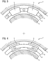
- the figure 3 shows an alternative embodiment of the bearing arrangement 1.
- the bearing assembly 1 In the in the figure 3 shown embodiment of the bearing assembly 1 are arranged around a non-illustrated axis of rotation several bearing stones 5.
- the bearing stones 5 can be of identical design.
- a plurality of bearing jewels 5 are arranged one behind the other in the bearing gap 4 seen in the direction of movement, the bearing jewels 5 being connected to one another by means of connecting elements 8 between the bearing jewels 5 .
- the connecting elements 8 each connect two bearing jewels 5 to one another. There is a connection between the connecting element 8 and the bearing jewel 5 so that the connecting element 8 is arranged between the bearing jewels 5 .
- the figure 4 shows a further variant of the bearing arrangement 1 according to the invention.
- the fastening means 9 can be designed as a screw or as a pin.
- the figure 5 shows a further embodiment of the bearing arrangement 1 according to the invention.
- the bearing stones 5 are arranged in such a way that they touch one another.
- a jewel 5 is wedge-shaped.
- a jewel 5 comprises a wedge-shaped end 10 and a wide opposite end 11.
- the wedge-shaped end 10 of a jewel 5 touches the wide opposite end 11 of an adjacent jewel 5.
- the taper is not necessarily wedge-shaped, but can also be tapered as desired .
- the bearing jewels 5 do not necessarily have to be wedge-shaped. Another shape is also possible.
- the jewel bearings 5 are wedge-shaped as viewed in the axial direction in cross section.
- the figure 6 shows a further embodiment of the bearing arrangement 1 according to the invention.
- the bearing blocks 5 are arranged in the bearing housing 12 in such a way that a displacement of the bearing blocks 5 in relation to the bearing housing 12 in the axial direction 13 is prevented.
- the bearing housing 12 has a projection 16 on the axial ends 15 of the bearing blocks 5, with which an axial displacement of the bearing block 5 is prevented.
- the figure 7 shows an alternative embodiment of the bearing arrangement 1 according to the invention.
- the bearing blocks 5 Seen in the circumferential direction, the bearing blocks 5 have a spherical or wedge-shaped surface 17 in cross section, with the bearing housing 12 having a surface complementary to the spherical or wedge-shaped surface 17 .
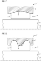
- the figure 8 shows a further alternative embodiment of the bearing arrangement 1 according to the invention.
- the bearing blocks 5 have a free surface 18 seen in cross section in the circumferential direction, with the bearing housing 12 having a surface complementary to the free surface 18 .
- the figure 9 shows a state of the bearing assembly 1 during operation. It can happen that the bearing stones 5 perform a tilting movement due to the forces prevailing during operation. This could result in parts of the bearing jewel 5 hitting the first bearing body 2 or the second bearing body 3 .
- the figure 10 shows one opposite the figure 9 improved execution.
- the parts of the bearing jewel 5 that threaten to hit the first bearing body 2 or the second bearing body 3 as a result of the tilting are flattened by removing part of the material from the bearing jewel.
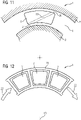
- the figure 11 shows a further embodiment of the bearing assembly 1 according to the invention.
- the bearing stones 5 have a connecting channel 19 which is a fluidic connection between a first gap 20 which is formed between the bearing stone 5 and the first bearing body 2 and a second gap 21 which is between the bearing jewel 5 and the second bearing body 3 is formed, manufactures.
- Oil is exchanged between the inner and outer sliding surfaces through this fluidic connection, which is designed as an oil channel.
- a further effect is that the bearing jewels 5 flooded with oil are cooled by the oil flow.
- the figure 12 shows an alternative embodiment of the bearing arrangement 1 according to the invention seen in the axial direction 13, the circumferential direction being represented by the arrows 22.
- the bearing stones 5 are arranged here in a cage 23 which prevents the bearing stones 5 from shifting in the axial direction 13 .
Landscapes
- Engineering & Computer Science (AREA)
- General Engineering & Computer Science (AREA)
- Mechanical Engineering (AREA)
- Physics & Mathematics (AREA)
- Fluid Mechanics (AREA)
- Sliding-Contact Bearings (AREA)
Priority Applications (1)
| Application Number | Priority Date | Filing Date | Title |
|---|---|---|---|
| EP21157288.8A EP4043742A1 (fr) | 2021-02-16 | 2021-02-16 | Ensemble palier |
Applications Claiming Priority (1)
| Application Number | Priority Date | Filing Date | Title |
|---|---|---|---|
| EP21157288.8A EP4043742A1 (fr) | 2021-02-16 | 2021-02-16 | Ensemble palier |
Publications (1)
| Publication Number | Publication Date |
|---|---|
| EP4043742A1 true EP4043742A1 (fr) | 2022-08-17 |
Family
ID=74661268
Family Applications (1)
| Application Number | Title | Priority Date | Filing Date |
|---|---|---|---|
| EP21157288.8A Withdrawn EP4043742A1 (fr) | 2021-02-16 | 2021-02-16 | Ensemble palier |
Country Status (1)
| Country | Link |
|---|---|
| EP (1) | EP4043742A1 (fr) |
Citations (8)
| Publication number | Priority date | Publication date | Assignee | Title |
|---|---|---|---|---|
| DE667761C (de) * | 1936-09-10 | 1938-11-19 | Anthony George Maldon Michell | Lager fuer Wellen |
| DE746868C (de) * | 1941-02-27 | 1944-08-28 | Glyco Metall Werke | Schwimmende Lagerbuechse |
| GB582967A (en) * | 1943-09-28 | 1946-12-03 | Anthony George Maldon Michell | Improvements in bearings |
| US2534788A (en) * | 1943-09-28 | 1950-12-19 | Michell Anthony George Maldon | Bearing |
| US2724622A (en) * | 1944-08-23 | 1955-11-22 | Michell Anthony George Maldon | Film-lubricated bearings |
| DE1052753B (de) * | 1955-11-24 | 1959-03-12 | Maschf Augsburg Nuernberg Ag | Gleitlager mit in kreisfoermige Segmente unterteilter Lagerbuechse fuer zwei verschiedene Drehrichtungen |
| US3421799A (en) * | 1967-05-10 | 1969-01-14 | Skf Ind Inc | Elastohydrodynamic sliding bearings |
| SU964288A1 (ru) * | 1979-10-09 | 1982-10-07 | Всесоюзное Научно-Производственное Объединение "Союзтурбогаз" | Многоклиновой радиальный подшипник |
-
2021
- 2021-02-16 EP EP21157288.8A patent/EP4043742A1/fr not_active Withdrawn
Patent Citations (8)
| Publication number | Priority date | Publication date | Assignee | Title |
|---|---|---|---|---|
| DE667761C (de) * | 1936-09-10 | 1938-11-19 | Anthony George Maldon Michell | Lager fuer Wellen |
| DE746868C (de) * | 1941-02-27 | 1944-08-28 | Glyco Metall Werke | Schwimmende Lagerbuechse |
| GB582967A (en) * | 1943-09-28 | 1946-12-03 | Anthony George Maldon Michell | Improvements in bearings |
| US2534788A (en) * | 1943-09-28 | 1950-12-19 | Michell Anthony George Maldon | Bearing |
| US2724622A (en) * | 1944-08-23 | 1955-11-22 | Michell Anthony George Maldon | Film-lubricated bearings |
| DE1052753B (de) * | 1955-11-24 | 1959-03-12 | Maschf Augsburg Nuernberg Ag | Gleitlager mit in kreisfoermige Segmente unterteilter Lagerbuechse fuer zwei verschiedene Drehrichtungen |
| US3421799A (en) * | 1967-05-10 | 1969-01-14 | Skf Ind Inc | Elastohydrodynamic sliding bearings |
| SU964288A1 (ru) * | 1979-10-09 | 1982-10-07 | Всесоюзное Научно-Производственное Объединение "Союзтурбогаз" | Многоклиновой радиальный подшипник |
Similar Documents
| Publication | Publication Date | Title |
|---|---|---|
| DE69309607T2 (de) | Aus Diamant bestehender Lagerzusammenbau | |
| DE60208935T2 (de) | Rollenlager und die rollenlager aufweisende kette | |
| DE102009021641A1 (de) | Wälzlager | |
| DE19738331A1 (de) | Lagerkäfig | |
| EP3186524B1 (fr) | Palier axial et support | |
| DE69407724T2 (de) | Abdichtungsvorrichtung für einen Fluidumdurchgang durch ein Rollenlager, und Rollenlager mit dieser Vorrichtung | |
| DE19749761A1 (de) | Entkoppelte Riemenscheibe | |
| DE69019542T2 (de) | Keramikgleitlager. | |
| WO2009056403A1 (fr) | Palier axial, en particulier pour un turbocompresseur | |
| DE2830818C2 (de) | Einsetzbarer Bordring für ein Radialwälzlager | |
| DE1966008A1 (de) | Kugellager | |
| WO2013079535A1 (fr) | Joint labyrinthe comprenant des bagues à labyrinthe à usure différentielle | |
| EP2980427A1 (fr) | Dispositif de palier lisse | |
| EP0222692B1 (fr) | Roulement | |
| DE2627604A1 (de) | Rotations-druckmittelstelltrieb | |
| EP0353407B1 (fr) | Cage à doigts de séparation pour roulement à rouleaux de grande dimension | |
| EP3094873B1 (fr) | Palier lisse hydrodynamique | |
| DE3211612C2 (de) | Kreuzgelenk | |
| DE3246863A1 (de) | Waelzlager mit geteilter lagerhuelse | |
| DE102019131245A1 (de) | Lageranordnung und Verfahren zum Montieren einer solchen | |
| EP0071026A1 (fr) | Palier à roulement à matière d'amortissement | |
| DE3540322C2 (fr) | ||
| DE102009024122A1 (de) | Wälzlagerteil, insbesondere Wälzlagerring oder Wälzkörper | |
| DE8209546U1 (de) | Zahnradmaschine, insbesondere zahnradpumpe fuer loesungen oder schmelzen von polymeren | |
| DE102011004707B4 (de) | Dichtungsanordnung |
Legal Events
| Date | Code | Title | Description |
|---|---|---|---|
| PUAI | Public reference made under article 153(3) epc to a published international application that has entered the european phase |
Free format text: ORIGINAL CODE: 0009012 |
|
| STAA | Information on the status of an ep patent application or granted ep patent |
Free format text: STATUS: THE APPLICATION HAS BEEN PUBLISHED |
|
| AK | Designated contracting states |
Kind code of ref document: A1 Designated state(s): AL AT BE BG CH CY CZ DE DK EE ES FI FR GB GR HR HU IE IS IT LI LT LU LV MC MK MT NL NO PL PT RO RS SE SI SK SM TR |
|
| STAA | Information on the status of an ep patent application or granted ep patent |
Free format text: STATUS: THE APPLICATION IS DEEMED TO BE WITHDRAWN |
|
| 18D | Application deemed to be withdrawn |
Effective date: 20230218 |