EP4043798B1 - Appareil combiné et son procédé d'assemblage - Google Patents
Appareil combiné et son procédé d'assemblage Download PDFInfo
- Publication number
- EP4043798B1 EP4043798B1 EP21157488.4A EP21157488A EP4043798B1 EP 4043798 B1 EP4043798 B1 EP 4043798B1 EP 21157488 A EP21157488 A EP 21157488A EP 4043798 B1 EP4043798 B1 EP 4043798B1
- Authority
- EP
- European Patent Office
- Prior art keywords
- channel section
- wall
- cooking hob
- section
- worktop
- Prior art date
- Legal status (The legal status is an assumption and is not a legal conclusion. Google has not performed a legal analysis and makes no representation as to the accuracy of the status listed.)
- Active
Links
Images


Classifications
-
- F—MECHANICAL ENGINEERING; LIGHTING; HEATING; WEAPONS; BLASTING
- F24—HEATING; RANGES; VENTILATING
- F24C—DOMESTIC STOVES OR RANGES ; DETAILS OF DOMESTIC STOVES OR RANGES, OF GENERAL APPLICATION
- F24C15/00—Details
- F24C15/20—Removing cooking fumes
- F24C15/2042—Devices for removing cooking fumes structurally associated with a cooking range e.g. downdraft
Definitions
- the present invention relates to a combination appliance comprising a cooking hob and an extraction device for removing air, specifically cooking vapours, from an area above the cooking hob according to the preamble of claim 1.
- the present invention further relates to a method for assembling a combination appliance comprising a cooking hob and an extraction device according to claim 11.
- Such kind of extraction device is usually arranged below a worktop of the related cooking hob and it comprises at least one fan for sucking air from the cooking area through an opening arranged in the worktop.
- Such a configuration of a cooking hob and an extraction device being connected together in a combined arrangement is commonly called a combination appliance.
- DE 10 2017 121367 A1 discloses the preamble of claim 1, disclosing a downdraft extractor hood with an air conveying channel having a box-shaped design and being positioned below a cooking surface.
- the air conveying channel is vertically arranged and includes two channel halves, which each communicate in a lower lateral area with an exhaust air suction chamber.
- a bottom wall of the air conveying channel is arranged in close proximity to a bottom wall of the exhaust air suction chamber.
- US 2018/229171 A1 discloses a filter unit for a fume extraction device of a combination appliance, also comprising a cooktop.
- the fume extraction device includes a filter unit with a filter element and a collection region partially surrounding the filter unit for collecting a liquid.
- the collection region is formed in an overflow container, which is fixedly connected to the cover plate of the cooktop. Between the overflow container and the cover plate of the cooktop, a sealing ring is provided, which is received in a sealing slot on an upper edge of the overflow container.
- DE 10 2016 130828 A1 discloses an extractor hood for the extraction of fumes below a hob plate through a suction opening.
- An air conveying channel is positioned below the suction opening.
- the air conveying channel includes a filter element for the filtration of the air stream. After passing the filter element, the air stream leaves the air conveying channel through an air outlet opening at a lower section of a channel side wall and is forwarded to a fan, which is configured to produce the airflow.
- a combination appliance in particular for domestic use, comprises a cooking hob and an extraction device.
- the cooking hob configured for cooking a food item thereon, is covered by a top plate or a worktop, which may be a glass plate.
- the top plate or worktop includes an opening or a recess that is formed therein providing a passage through the top plate or worktop.
- the extraction device is arranged below the top plate or worktop and comprises at least one fan for sucking air from an area above the cooking hob through the opening or recess of the top plate or worktop and for conveying the air through an air channel of the extraction device.
- the air channel of the extraction device includes a channel section, which is arranged downstream of the opening or recess and upstream of the fan.
- the channel section is further arranged adjacent to components, in particular electrical and/or electronic components, of the cooking hob. More specifically because of an impenetrable wall, the channel section forms a barrier for the prevention of the conveyed air to get in contact with the components of the cooking hob.
- the channel section comprises an upper portion and a lower portion.
- the upper portion which is particularly a top edge or top surface, abuts a surface zone of the top plate or worktop, particularly of the bottom of the top plate or worktop.
- the lower portion which is particularly a bottom surface, abuts and/or is supported by a wall section of the cooking hob.
- Said wall section is in particular a bottom wall section or a side wall section or an intermediate wall section.
- the cooking hob being the source for the aspirated cooking vapours may be of any type including electric or gas cooking hobs.
- the electric cooking hob is an induction cooking hob.
- the cooking hob may further be an autarkic cooking appliance, particularly integrated in a countertop of kitchen furniture, or it may be part of a stove.
- a top surface of the top plate or worktop, which is accessible to a user, may be used for putting cookware thereon, specifically in order to perform a cooking process.
- the cooking hob preferably comprises at least one heating element defining a cooking zone on the worktop or, specifically, the glass plate, which is favourably made out of glass ceramics.
- One particular advantage of the solution according to the present invention is the fact that the top surface of the top plate or worktop is entirely kept in a flat execution and there are no obstacles provided to the user of the appliance, when moving the cookware along the cooking surface.
- Said channel section particularly also further sections of the air channel, may be made in plastic or any other suitable material, e. g. sheet metal.
- the extraction device comprises an exhaust opening for blowing out the air into the atmosphere.
- Said exhaust opening is notably arranged at the end of the air channel downstream of the fan.
- at least one filter element or a filter unit may be arranged in the extraction device, more specifically in the path of the air stream, particularly inside of the air channel.
- a preferred embodiment of the present invention provides for a sealing means, which is arranged or arrangeable at the upper portion of the channel section, in particular between the upper portion and the surface zone of the top plate or worktop. Additionally, or alternatively, the sealing means may be arranged or arrangeable at the lower portion of the channel section, in particular between the lower portion and the wall section of the cooking hob. Said sealing means are adapted to hermetically seal the cooking hob, in particular components of the cooking hob, off from the air conveyed through the air channel. This allows an entire aspiration of the cooking vapours through the opening or recess and prevents any air bypass.
- One specific solution for the sealing means comprises a layer of glue, which is particularly a circumferential glue bead applied on or contacting the upper portion of the channel section.
- the upper portion of the channel section preferably surrounds a cross-sectional area of the interior space of the channel section. More preferably, the upper portion of the channel section surrounds a wall of the channel section.
- An entirely circumferential glue spread surrounding the interior of the channel section not only cares for a fixed connection between the top plate or worktop and the channel section, but also avoids any air bypass and allows to skip any specific additional sealing means.
- the upper portion of the channel section may comprise a circumferential rim or collar laterally protruding from the channel section wall.
- the circumferential rim or collar and the bottom of the top plate or worktop are preferably aligned parallel to one another. Additionally, or alternatively, the circumferential rim or collar are preferably arranged or arrangeable spaced from the bottom of the top plate or worktop.
- the space between the circumferential rim or collar and the bottom of the top plate or worktop particularly forms a receiving space for the layer of glue. That way, the layer of glue is not squeezed out at any point of the area or its application, which would entail the risk of air leakage at a point without gluing.
- the channel section comprises a pipe section, which includes an insertion space for housing a filter element or a filter unit.
- the channel section and/or pipe section may have any shape with an arbitrary cross section, however, a rectangular cross section, is a preferred solution for such section(s).
- the channel section may comprise a supporting means, notably a first supporting means, or a fixation means for a, preferably releasably, fixed positioning of a filter element or a filter unit.
- a supporting means notably a second supporting means, for supporting a grid or a lid adapted to cover the opening or recess may be included.
- Said second supporting means is particularly a supporting surface or supporting frame or supporting element.
- the extraction device may also be characterized by an outlet port of the channel section, which opens out into a suction compartment arranged downstream thereof and upstream of the fan.
- a circumferential protection edge is arranged at the upper portion of the channel section, which protection edge abuts lateral edges of a cutout of the top plate or worktop, wherein the cutout is specified by the opening or recess.
- the cutout is rectangular, specifically when also the channel section is of a rectangular shape.
- the protection edge is arranged at an inlet port located at the opening or recess, thus protecting the edges of the cutout from any mechanical damages.
- the combination appliance is advantageously characterized by a wall of the channel section, which comprises a double-walled structure including an inner channel section wall and an outer channel section wall. Moreover, the inner channel section wall opens out into a suction compartment arranged downstream thereof and upstream of the fan and particularly penetrates the bottom wall.
- the outer channel section wall is preferably supported by the bottom wall section of the cooking hob.
- Supporting ribs may be arranged between the inner channel section wall and the outer channel section wall. Said supporting ribs are particularly orthogonally arranged to the inner and outer channel section walls.
- a lower portion, which is a lower end surface, of the channel section wall is supported by a bottom wall section of the cooking hob.
- Said bottom wall section is more specified by a protrusion of the bottom wall protruding from a box or a compartment defined by walls, which comprise the bottom wall and a side wall adjacent to the channel section wall.
- the bottom wall section is a circumferential edge of a cutout in the bottom wall.
- the object is further achieved for a method for assembling a combination appliance comprising a cooking hob and an extraction device according to the features of claim 11.
- a method for assembling a combination appliance comprising a cooking hob and an extraction device, comprises at least a first and a second assembly step.
- a channel section of an air channel of the extraction device is connected to a top plate or worktop of the cooking hob in a way that an inlet port of the channel section is assigned to an opening or recess formed in the top plate or worktop.
- the connection between channel section and top plate or worktop is preferably performed in an airtight, i. e. hermetical, manner. More preferably, the channel section is glued on the top plate or worktop.
- the top plate or worktop is positioned on a substructure, in particular on a lower hob box, of the cooking hob.
- the channel section is arranged alongside the substructure or penetrates the channel section, so that, as a result, the channel section extends from the opening or recess of the top plate or worktop to or through a bottom wall, in particular to or through a cutout in the bottom wall, of the cooking hob.
- an outlet port of the channel section opens out or is provided to open out into a suction compartment of a fan of the extraction device.
- Said fan is configured for sucking air from the area above the cooking hob through the opening or recess of the top plate or worktop and for conveying the air through an air channel of the extraction device.
- the suction compartment of the fan is arranged beneath the cooking hob in an assembly step prior to the first step, between first and second steps or after the second step.
- the first assembly step may be performed at an installation location different from that one of the second assembly step.
- the first assembly step may be executed on a pre-assembly line.
- the channel section is connected during the first step to the top plate or worktop in a way that the central axis of the channel section passes through the centre of the opening or recess. That way, full alignment between the two involved components is established.
- a glue bead may be circumferentially applied on an upper portion, in particular on a top surface or top edge, of the channel section.
- the upper section preferably surrounds a cross-sectional area of the interior space of the channel section. More preferably, the upper section surrounds a wall of the channel section.
- the glue bead may by circumferentially applied on a border around the opening or recess of the bottom side of the top plate or worktop. More specifically, after said application of the glue bead, a glued joint is established between the upper portion of the channel section and the top plate or worktop. Said glue bead is not only provided for establishing a fixed connection, but also works as a sealing means for preventing air to pass through the respective junction.
- the lower portion of the channel section is set down during the second step on the bottom wall of the cooking hob. This joining of the two components is performed in particular in a final stage of the second step. On this occasion an at least approximately airtight junction is preferably established at the contact zone.
- Said lower portion may be a bottom surface or bottom edge of the channel section.
- Fig. 1 illustrates a combination appliance 10 comprising a cooking hob 12 and a downdraft extraction device 14 installed in a kitchen cabinet 16.
- the cooking hob 12 is implemented in a cutout of a kitchen countertop 18 forming a top cover plate of the kitchen cabinet 16.
- the downdraft extraction device 14 is configured to take away cooking vapours occurring during cooking processes, in particular when cooking with uncovered cookware.
- the cooking hob 12 comprises cooking regions 20a, 20b arranged on a left half and a right half of a cooktop 22 of the cooking hob 12, which left and right halves are separated from each other by a suction opening 24 for an intake of the cooking vapours, the suction opening 24 being arranged alongside a cooktop centreline.
- the suction opening 24 is covered by a cover grid 26 for preventing items, e. g. cookware, to fall into the suction opening 24.
- a lid may be used for entirely covering the suction opening when the extraction device 14 is out of use, but for the operation of the extraction device 14 the lid is pivotable into an upright open position.
- the flow of the sucked-in cooking vapours through the extraction device 14 is driven by the operation of an extraction fan 36 arranged inside of the casing 28.
- Said extraction fan 36 comprises a bottom-sided intake opening 38 for sucking the cooking vapours from the interior space of the casing 28.
- a rear-sided fan outlet (not shown) is arranged for a horizontal exit of the air blown out backwards from the extraction fan housing 42.
- the fan outlet is connected to a first end of an air duct 44 designed as a rectangular tube and forms a second channel arranged downstream the above-mentioned first channel.
- an air duct bending by 90 degrees is implemented, which redirects the air flow from horizontal to vertical downwards.
- the air duct 44 may be guided alongside a rear side of the kitchen cabinet 16 and may be bent again by 90 degrees close to a rear lower edge of the kitchen cabinet 16 in order to direct the airflow towards exhaust opening 30 in the base area 32 of the kitchen cabinet 16.
- the second end of the air duct 44 is connected to the exhaust opening 30.
- the embodiment illustrated in Fig. 1 shows a solution of the air duct 44 with an inclined section of its downwardly directed portion, directed slightly to the right. Naturally, a solution with said portion arranged in an exact vertical direction is considerable as well.
- a filter assembly 48 which is arranged downstream directly behind the suction opening 24 for providing a purification of the conveyed air.
- Said filter assembly 48 includes a filter carrier 50 supporting a filter element (not shown) that is usually configured for filtering out grease particles and droplets.
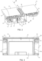
- the cross-sectional view of Fig. 2 further shows two power boards 54, one for the left cooking region 20a and one for the right cooking region 20b, the power boards 54 providing cooking zones in the left and right cooking regions 20a, 20b with electrical power.
- the cooking hob 12 is an induction cooking hob and the cooking zones are defined by induction coils (not shown) that are arranged below the cooktop 22 of the cooking hob 12. Attached to the bottom side of the power board 54 assigned to the right cooking region 20b, a further circuit board is arranged forming a control electronics 56 for the combination appliance 10.
- Fig. 3 illustrates a cross-sectional view of the upper section of the combination appliance 10 representing the area of localisation of the cooking hob 12. This means, that the combination appliance section beneath the cooking hob 12 is cut away.
- the viewing direction providing the illustration of Fig. 3 is shown in Fig. 2 .
- the presentation according to Fig. 3 represents the status of the filter assembly 48 being removed from its operating position according to Figs. 1 and 2 and shows a vertical cross-section through an initial channel section 58.
- the initial channel section is formed as a pipe section with a rectangular horizontal cross-section, which is defined by its front and rear (from user's perspective) channel walls 58a as well as its lateral channel walls 58b, the channel walls 58a, 58b forming a cuboid tube, with an inlet opening directly downstream of the suction opening 24 and an outlet opening opening out into the interior of the casing 28, which is a subsequent air channel segment directly downstream of the initial channel section 58.
- the casing 28 also works as a suction compartment, which provides the conveyed air to the fan 36 that aspirates the air through the intake opening 38.
- the filter assembly 48 is not present, however, the suction opening 24 is covered with grid 26.
- the initial channel section 58 On its bottom side, defining also the outlet opening, the initial channel section 58, more precisely the channel walls 58a, 58b of the channel section 58, rests on a bottom wall 60 of the cooking hob 12.
- the top sides of the channel walls 58a, 58b of the initial channel section 58 abut with their upper front faces a border around the suction opening 24 on the bottom surface of the cooktop 22. That way, the initial channel section 58 is sandwiched between the upper side of the bottom wall 60 of the cooking hob 12 and the bottom side of the cooktop 22.
- sealing means are arranged between the initial channel section 58, on the one hand, and the bottom surface of the cooktop 22 as well as the bottom wall 60 of the cooking hob 12, on the other hand.
- the sealing means on the top side of the initial channel section 58 is realized by a circumferential glue bead 62 continuously surrounding the upper front faces of the channel walls 58a, 58b of the initial channel section 58.
- the upper portion of the initial channel section 58 comprises a circumferential rim 64 laterally protruding from the upper end of the channel walls 58a, 58b.
- the circumferential rim 64 and the bottom surface of the cooktop 22 are aligned parallel to one another and the circumferential rim 64 is arranged spaced from the bottom surface of the cooktop 22, wherein the space between the circumferential rim 64 and the bottom surface of the cooktop 22 forms said receiving space for the glue bead 62.
- the sealing on the bottom side of the initial channel section 58 according to the embodiment of Figs 3 and 4 is simply realized by a firm touching or pressing of the lower front faces of the channel walls 58a, 58b of the initial channel section 58 onto the upper side of the bottom wall 60 of the cooking hob 12, or more precisely, on a border around a cutout in the bottom wall 60 adjacent to the outlet opening of the initial channel section 58, which cutout provides a passage for the conveyed air from the initial channel section 58 to the interior of the casing 28.
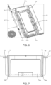
- Figs. 5 and 6 illustrate a second example of the initial channel section 58.
- the initial channel section 58 comprises a double-walled structure including an inner channel section wall 66a and an outer channel section wall 66b.
- both inner and outer channel section walls 66a, 66b comprise four single walls, analogous to front and rear walls 58a and lateral walls 58b of the above-described first example.
- the inner channel section wall 66a opens out into the casing 22 and penetrates the bottom wall 60 of the cooking hob 12, thereby protruding somewhat from the lower surface of the bottom wall 60.
- the outer channel section wall 66b rests on the bottom wall section of the cooking hob 12.
- the sealing effect of the second example is increased by an arrangement of two such minimized gaps in series, i. e. both the inner channel section wall 66a and the outer channel section wall 66b of the double-walled channel section about the bottom wall 60 of the cooking hob 12, either on the top surface of the bottom wall 60 (see outer channel section wall 66b) or laterally against the cutout edge (see inner channel section wall 66a).
- This way of two contacting areas with only small gaps implemented in series increase the sealing effect.
- supporting ribs 68 are arranged between the inner channel section wall 66a and the outer channel section wall 66b. Said supporting ribs 68 are orthogonally arranged to the inner 66a and outer 66b channel section walls. Further supporting ribs 68 are arranged at the outer surface of the outer channel section wall 66b, which are adapted to rest against an inner wall 70 of the cooking hob 12.
- a third example of the initial channel section 58 is shown.
- the embodiment according to this third example is almost entirely congruent with the embodiment of the first example (see particularly Fig. 3 ).
- the only difference to the first example concerns a circumferential protection edge 72, which is arranged at the inlet port located at the suction opening 24 of the channel section 58.
- the protection edge 72 abuts against lateral edges of the cutout of the glass cooktop 22, which cutout is specified by the suction opening 24. Due to its function of covering said cutout edges, the circumferential protection edge 72 thus protects these cutout edges from any mechanical damages.
Landscapes
- Engineering & Computer Science (AREA)
- Chemical & Material Sciences (AREA)
- Combustion & Propulsion (AREA)
- Mechanical Engineering (AREA)
- General Engineering & Computer Science (AREA)
- Electric Stoves And Ranges (AREA)
- Ventilation (AREA)
- Resistance Heating (AREA)
Claims (14)
- Appareil combiné (10), comprenant- une table de cuisson (12), qui est recouverte d'une plaque de dessus ou d'un plan de travail (22), en particulier d'une plaque de verre, dans lesquels sont ménagés une ouverture (24) ou un renfoncement,
et- un dispositif d'extraction (14), qui est agencé au-dessous de la plaque de dessus ou du plan de travail (22) et comprend au moins un ventilateur (36) destiné à aspirer l'air d'une région située au-dessus de la table de cuisson (12) à travers l'ouverture (24) ou le renfoncement de la plaque de dessus ou du plan de travail (22) et destiné à acheminer l'air à travers un canal d'air du dispositif d'extraction (14),le canal d'air du dispositif d'extraction (14) comportant un tronçon de canal (58), qui est agencé en aval de l'ouverture (24) ou du renfoncement et en amont du ventilateur (36), lequel tronçon de canal (58) est agencé adjacent à des composants, en particulier à des composants électriques et/ou électroniques, de la table de cuisson (12), le tronçon de canal (58) formant de cette manière une barrière destinée à empêcher l'air acheminé d'entrer au contact des composants de la table de cuisson (12),et le tronçon de canal (58) comprenant- une partie supérieure, en particulier un bord de dessus ou une surface de dessus, venant en butée contre une zone de surface de la plaque de dessus ou du plan de travail (22), en particulier du dessous de la plaque de dessus ou du plan de travail (22),
et- une partie inférieure, en particulier une surface de dessous, venant en butée contre un tronçon de paroi et/ou supportée par lui, en particulier un tronçon de paroi de dessous (60) ou un tronçon de paroi latéral ou un tronçon de paroi intermédiaire, de la table de cuisson (12),caractérisé en ce queune surface d'extrémité inférieure de la paroi (58a, 58b, 66b) de tronçon de canal est supportée par un tronçon de paroi de dessous (60) de la table de cuisson (12)- par une protubérance de la paroi de dessous (60) en saillie depuis un caisson ou un compartiment défini par des parois, lesquelles comprennent la paroi de dessous (60) et une paroi latérale adjacente à la paroi (58a, 58b, 66b) de tronçon de canal,
ou- par un bord ou une bordure circonférentiels d'une découpe dans la paroi de dessous (60). - Appareil combiné (10) selon la revendication 1, caractérisé en ce queun moyen faisant étanchéité est agencé ou agençable- au niveau de la partie supérieure du tronçon de canal (58), en particulier entre la partie supérieure et la zone de surface de la plaque de dessus ou du plan de travail (22),
et/ou- au niveau de la partie inférieure du tronçon de canal (58), en particulier entre la partie inférieure et le tronçon de paroi (60) de la table de cuisson (12),le moyen faisant étanchéité étant adapté à rendre la table de cuisson (12), en particulier des composants de la table de cuisson (12), hermétiques à l'air acheminé à travers le canal d'air. - Appareil combiné (10) selon la revendication 2,
caractérisé en ce que
le moyen faisant étanchéité comprend une couche de colle, en particulier un cordon circonférentiel de colle (62) appliqué sur la partie supérieure du tronçon de canal (58) ou venant à son contact, la partie supérieure du tronçon de canal (58) entourant de préférence une section transversale de l'espace intérieur du tronçon de canal (58). - Appareil combiné (10) selon la revendication 2 ou 3,
caractérisé en ce que
la partie supérieure du tronçon de canal (58) comprend un rebord circonférentiel (64) ou une bride circonférentielle faisant saillie latéralement depuis la paroi (58a, 58b) de tronçon de canal, le rebord circonférentiel (64) ou la bride circonférentielle étant agencés ou agençables espacés du dessous de la plaque de dessus ou du plan de travail (22), l'espace entre le rebord circonférentiel (64) ou la bride circonférentielle et le dessous de la plaque de dessus ou du plan de travail (22) formant plus particulièrement un espace de réception pour la couche de colle (62). - Appareil combiné (10) selon l'une quelconque des revendications précédentes,
caractérisé en ce que
le tronçon de canal (58) comprend un tronçon de conduit, en particulier pourvu d'une section transversale rectangulaire, qui comporte un espace d'insertion pour accueillir un élément de filtration ou une unité de filtration (48). - Appareil combiné (10) selon l'une quelconque des revendications précédentes,
caractérisé en ce que
le tronçon de canal (58) comprend- un premier moyen de support ou moyen de fixation pour positionner de manière fixe, de préférence amovible, un élément de filtration ou une unité de filtration (48),
et/ou- un deuxième moyen de support, de préférence une surface de support ou un cadre de support ou un élément de support, pour supporter une grille (26) ou un couvercle pour recouvrir l'ouverture (24) ou le renfoncement. - Appareil combiné (10) selon l'une quelconque des revendications précédentes,
caractérisé en ce que
un orifice de sortie du tronçon de canal (58) débouche dans un compartiment d'aspiration (28) agencé en amont du ventilateur (36). - Appareil combiné (10) selon l'une quelconque des revendications précédentes,
caractérisé en ce que
un bord de protection circonférentiel (72) est agencé au niveau de la partie supérieure, en particulier au niveau d'un orifice d'entrée situé au niveau de l'ouverture (24) ou du renfoncement, du tronçon de canal (58), lequel bord de protection (72) vient en butée contre des bords latéraux d'une découpe, plus particulièrement rectangulaire, de la plaque de dessus ou du plan de travail (22). - Appareil combiné (10) selon l'une quelconque des revendications précédentes,
caractérisé en ce que
une paroi (58a, 58b) du tronçon de canal (58) comprend une structure à double paroi comportant une paroi intérieure (66a) de tronçon de canal et une paroi extérieure (66b) de tronçon de canal, la paroi extérieure (66b) de tronçon de canal étant de préférence supportée par le tronçon de paroi de dessous (60) de la table de cuisson (12), la paroi intérieure (66a) de tronçon de canal débouchant dans un compartiment d'aspiration (28) agencé en amont du ventilateur (36) et, plus particulièrement, pénétrant dans la paroi de dessous (60) de la table de cuisson (12). - Appareil combiné (10) selon la revendication 9,
caractérisé en ce que
des nervures de support (68) sont agencées entre la paroi intérieure (66a) de tronçon de canal et la paroi extérieure (66b) de tronçon de canal, lesquelles nervures de support (68) sont plus particulièrement agencées orthogonalement aux parois intérieure (66a) et extérieure (66b) de tronçon de canal. - Procédé d'assemblage d'un appareil combiné (10) comprenant une table de cuisson (12) et un dispositif d'extraction (14) selon l'une quelconque des revendications précédentes, dans lequel- à une première étape, un tronçon de canal (58) d'un canal d'air du dispositif d'extraction (14) est relié à, de préférence collé sur, une plaque de dessus ou un plan de travail (22) de la table de cuisson (12) de telle manière qu'un orifice d'entrée du tronçon de canal (58) est assigné à une ouverture (24) ou un renfoncement ménagés dans la plaque de dessus ou le plan de travail (22),
et- à une deuxième étape, la plaque de dessus ou le plan de travail (22) sont positionnés sur une sous-structure, en particulier un caisson de table inférieur, de la table de cuisson (12), de manière à agencer le tronçon de canal (58) le long de la sous-structure ou à faire pénétrer le tronçon de canal (58) dans la sous-structure, de sorte que le tronçon de canal (58) s'étend depuis l'ouverture (24) ou le renfoncement de la plaque de dessus ou du plan de travail (22) jusqu'à ou à travers une paroi de dessous (60), en particulier jusqu'à ou à travers une découpe dans la paroi de dessous (60), de la table de cuisson (12), un orifice de sortie du tronçon de canal (58) débouchant ou étant ménagé pour déboucher dans un compartiment d'aspiration (28) d'un ventilateur (36) du dispositif d'extraction (14), le ventilateur (36) étant configuré pour aspirer l'air de la région située au-dessus de la table de cuisson (12) à travers l'ouverture (24) ou le renfoncement de la plaque de dessus ou du plan de travail (22) et pour acheminer l'air à travers un canal d'air du dispositif d'extraction (14),et dans lequel le compartiment d'aspiration (28) du ventilateur (36) est agencé au-dessous de la table de cuisson (12) préalablement à la première étape, entre les première et deuxième étapes ou à la suite de la deuxième étape. - Procédé selon la revendication 11,
caractérisé en ce que
au cours de la première étape, le tronçon de canal (58) est relié à la plaque de dessus ou au plan de travail (22) de telle manière que l'axe central du tronçon de canal (58) passe par le centre de l'ouverture (24) ou du renfoncement. - Procédé selon la revendication 11 ou 12,
caractérisé en ce que
préalablement à la première étape ou au début de celle-ci, un cordon de colle (62) est appliqué circonférentiellement- sur une partie supérieure, en particulier sur une surface de dessus ou un bord de dessus, du tronçon de canal (58), la partie supérieure entourant de préférence une section transversale de l'espace intérieur du tronçon de canal (58) ou une paroi (58a, 58b) du tronçon de canal (58), ou- sur une bordure autour de l'ouverture (24) ou du renfoncement du côté de dessous de la plaque de dessus ou du plan de travail (22). - Procédé selon l'une quelconque des revendications 11 à 13,
caractérisé en ce que
au cours de la deuxième étape, en particulier dans sa phase finale, la partie inférieure, en particulier une surface de dessous ou un bord de dessous, du tronçon de canal (58) est posée sur la paroi de dessous (60) de la table de cuisson (12), en particulier en établissant à cette occasion une jonction au moins approximativement étanche à l'air au niveau de la zone de contact.
Priority Applications (3)
| Application Number | Priority Date | Filing Date | Title |
|---|---|---|---|
| EP21157488.4A EP4043798B1 (fr) | 2021-02-16 | 2021-02-16 | Appareil combiné et son procédé d'assemblage |
| PCT/EP2022/052473 WO2022175089A1 (fr) | 2021-02-16 | 2022-02-02 | Appareil combiné et son procédé d'assemblage |
| AU2022222183A AU2022222183A1 (en) | 2021-02-16 | 2022-02-02 | Combination appliance and method for assembling the same |
Applications Claiming Priority (1)
| Application Number | Priority Date | Filing Date | Title |
|---|---|---|---|
| EP21157488.4A EP4043798B1 (fr) | 2021-02-16 | 2021-02-16 | Appareil combiné et son procédé d'assemblage |
Publications (2)
| Publication Number | Publication Date |
|---|---|
| EP4043798A1 EP4043798A1 (fr) | 2022-08-17 |
| EP4043798B1 true EP4043798B1 (fr) | 2025-04-09 |
Family
ID=74666500
Family Applications (1)
| Application Number | Title | Priority Date | Filing Date |
|---|---|---|---|
| EP21157488.4A Active EP4043798B1 (fr) | 2021-02-16 | 2021-02-16 | Appareil combiné et son procédé d'assemblage |
Country Status (3)
| Country | Link |
|---|---|
| EP (1) | EP4043798B1 (fr) |
| AU (1) | AU2022222183A1 (fr) |
| WO (1) | WO2022175089A1 (fr) |
Family Cites Families (18)
| Publication number | Priority date | Publication date | Assignee | Title |
|---|---|---|---|---|
| US2674991A (en) * | 1951-02-08 | 1954-04-13 | Philco Corp | Ventilating means for cooking ranges |
| US5209217A (en) * | 1992-07-24 | 1993-05-11 | Maytag Corporation | Downdraft gas range with dual mode burner system |
| US6455818B1 (en) * | 2001-08-23 | 2002-09-24 | Maytag Corporation | Downdraft filter assembly for a cooking appliance |
| US7687748B2 (en) * | 2005-08-01 | 2010-03-30 | Western Industries, Inc. | Induction cook top system with integrated ventilator |
| US20070062513A1 (en) * | 2005-09-21 | 2007-03-22 | Gagas John M | Cooking system with ventilator and blower |
| DE202009008286U1 (de) * | 2009-06-10 | 2009-09-24 | Bruckbauer, Wilhelm | Kochdunst-Eintrittsvorrichtung mit abnehmbarer deckelförmiger Verschließeinrichtung |
| DE102013206748B4 (de) * | 2012-04-17 | 2022-06-02 | BSH Hausgeräte GmbH | Dunstabzugsvorrichtung mit mindestens einem Rost |
| EP3338030B1 (fr) * | 2015-08-19 | 2019-12-18 | BSH Hausgeräte GmbH | Appareil combiné avec plaque de cuisson et dispositif d'evacuation des fumées avec unité de filtration |
| EP3133350B1 (fr) * | 2015-08-19 | 2020-11-04 | BSH Hausgeräte GmbH | Unite combinee comprenant une zone de cuisson et un dispositif d'aspiration de fumees comprenant une unite de filtration |
| CN108348831B (zh) * | 2015-11-10 | 2021-04-13 | Bsh家用电器有限公司 | 用于蒸汽排除装置的过滤装置和蒸汽排除装置 |
| AU2017327522A1 (en) * | 2016-09-14 | 2019-03-28 | Electrolux Home Products, Inc. | Variable height downdraft built into cooking device |
| DE102017121367B4 (de) * | 2017-09-14 | 2021-07-22 | Berbel Ablufttechnik Gmbh | Dunstabzug zum Abzug von auf einem Kochfeld erzeugter Abluft in vertikal unterhalb einer Kochfeldebene weisender Richtung |
| US11885505B2 (en) * | 2018-04-10 | 2024-01-30 | BSH Hausgeräte GmbH | Filter device and fume extraction device comprising filter device |
| DE202019106084U1 (de) * | 2018-11-07 | 2019-11-15 | Elica S.P.A | Kochfläche mit Downdraft-Dunstabzugshaube |
| DE102018130828A1 (de) * | 2018-12-04 | 2020-06-04 | Miele & Cie. Kg | Dunstabzug |
| DE102018221342A1 (de) * | 2018-12-10 | 2020-06-10 | BSH Hausgeräte GmbH | Dunstabzugsvorrichtung und Küchengerät mit Kochfeld und Dunstabzugsvorrichtung |
| DE102019104069A1 (de) * | 2019-02-19 | 2020-08-20 | Miele & Cie. Kg | Kochfeldsystem |
| WO2020152288A1 (fr) * | 2019-01-24 | 2020-07-30 | BSH Hausgeräte GmbH | Dispositif d'évacuation des émanations pour plaque de cuisson et appareil combiné |
-
2021
- 2021-02-16 EP EP21157488.4A patent/EP4043798B1/fr active Active
-
2022
- 2022-02-02 WO PCT/EP2022/052473 patent/WO2022175089A1/fr not_active Ceased
- 2022-02-02 AU AU2022222183A patent/AU2022222183A1/en active Pending
Also Published As
| Publication number | Publication date |
|---|---|
| WO2022175089A1 (fr) | 2022-08-25 |
| AU2022222183A1 (en) | 2023-08-03 |
| EP4043798A1 (fr) | 2022-08-17 |
Similar Documents
| Publication | Publication Date | Title |
|---|---|---|
| US11732901B2 (en) | Ventilation apparatus and ventilation system including the same | |
| US10900665B2 (en) | Combination appliance having a cooktop and steam extraction device | |
| US10704557B2 (en) | Suction device for a range hood comprising a volute including a first semi-shell and a second semi-shell forming a compartment for housing a capacitor and a connector electrically coupled to an electric motor | |
| US7193195B2 (en) | Wall mounted microwave oven having a top vent with filter system | |
| EP4193092A1 (fr) | Appareil combiné | |
| CN1332153C (zh) | 炉灶上方的多功能微波炉 | |
| US20240085031A1 (en) | Extraction device | |
| KR20260049515A (ko) | 후드 겸용 조리기기 | |
| EP4043798B1 (fr) | Appareil combiné et son procédé d'assemblage | |
| US7019272B2 (en) | Wall mounted microwave oven having an exhaust ventilation system | |
| JP4495474B2 (ja) | Ihクッキングヒータ用のレンジフード | |
| EP1635121B1 (fr) | Installation de hotte de ventilation | |
| EP4332441A1 (fr) | Ensemble filtre et appareil combiné | |
| JP4495475B2 (ja) | Ihクッキングヒータ用のレンジフード | |
| EP1630477B1 (fr) | Hotte de ventilation pour cuisine | |
| EP4368899A1 (fr) | Système d'extraction de fumées et méthode d'utilisation d'un dispositif d'extraction | |
| KR100551489B1 (ko) | 벽걸이형 전자렌지 | |
| KR102848838B1 (ko) | 조리 기기 | |
| EP4286750A1 (fr) | Dispositif d'extraction, appareil combiné et procédé de fonctionnement d'un dispositif d'extraction ou d'un appareil combiné | |
| JP2604501B2 (ja) | 排気フード構造 | |
| JP2612943B2 (ja) | レンジフード | |
| CN116745558A (zh) | 抽取设备 | |
| CN118208753A (zh) | 一种排放装置以及集成灶 | |
| KR20070034216A (ko) | 전자렌지 |
Legal Events
| Date | Code | Title | Description |
|---|---|---|---|
| PUAI | Public reference made under article 153(3) epc to a published international application that has entered the european phase |
Free format text: ORIGINAL CODE: 0009012 |
|
| STAA | Information on the status of an ep patent application or granted ep patent |
Free format text: STATUS: THE APPLICATION HAS BEEN PUBLISHED |
|
| AK | Designated contracting states |
Kind code of ref document: A1 Designated state(s): AL AT BE BG CH CY CZ DE DK EE ES FI FR GB GR HR HU IE IS IT LI LT LU LV MC MK MT NL NO PL PT RO RS SE SI SK SM TR |
|
| STAA | Information on the status of an ep patent application or granted ep patent |
Free format text: STATUS: REQUEST FOR EXAMINATION WAS MADE |
|
| 17P | Request for examination filed |
Effective date: 20230217 |
|
| RBV | Designated contracting states (corrected) |
Designated state(s): AL AT BE BG CH CY CZ DE DK EE ES FI FR GB GR HR HU IE IS IT LI LT LU LV MC MK MT NL NO PL PT RO RS SE SI SK SM TR |
|
| GRAP | Despatch of communication of intention to grant a patent |
Free format text: ORIGINAL CODE: EPIDOSNIGR1 |
|
| STAA | Information on the status of an ep patent application or granted ep patent |
Free format text: STATUS: GRANT OF PATENT IS INTENDED |
|
| INTG | Intention to grant announced |
Effective date: 20241111 |
|
| P01 | Opt-out of the competence of the unified patent court (upc) registered |
Free format text: CASE NUMBER: APP_68049/2024 Effective date: 20241226 |
|
| GRAS | Grant fee paid |
Free format text: ORIGINAL CODE: EPIDOSNIGR3 |
|
| GRAA | (expected) grant |
Free format text: ORIGINAL CODE: 0009210 |
|
| STAA | Information on the status of an ep patent application or granted ep patent |
Free format text: STATUS: THE PATENT HAS BEEN GRANTED |
|
| AK | Designated contracting states |
Kind code of ref document: B1 Designated state(s): AL AT BE BG CH CY CZ DE DK EE ES FI FR GB GR HR HU IE IS IT LI LT LU LV MC MK MT NL NO PL PT RO RS SE SI SK SM TR |
|
| REG | Reference to a national code |
Ref country code: GB Ref legal event code: FG4D |
|
| REG | Reference to a national code |
Ref country code: CH Ref legal event code: EP |
|
| REG | Reference to a national code |
Ref country code: DE Ref legal event code: R096 Ref document number: 602021028744 Country of ref document: DE |
|
| REG | Reference to a national code |
Ref country code: IE Ref legal event code: FG4D |
|
| REG | Reference to a national code |
Ref country code: NL Ref legal event code: MP Effective date: 20250409 |
|
| PG25 | Lapsed in a contracting state [announced via postgrant information from national office to epo] |
Ref country code: NL Free format text: LAPSE BECAUSE OF FAILURE TO SUBMIT A TRANSLATION OF THE DESCRIPTION OR TO PAY THE FEE WITHIN THE PRESCRIBED TIME-LIMIT Effective date: 20250409 |
|
| PG25 | Lapsed in a contracting state [announced via postgrant information from national office to epo] |
Ref country code: ES Free format text: LAPSE BECAUSE OF FAILURE TO SUBMIT A TRANSLATION OF THE DESCRIPTION OR TO PAY THE FEE WITHIN THE PRESCRIBED TIME-LIMIT Effective date: 20250409 Ref country code: PT Free format text: LAPSE BECAUSE OF FAILURE TO SUBMIT A TRANSLATION OF THE DESCRIPTION OR TO PAY THE FEE WITHIN THE PRESCRIBED TIME-LIMIT Effective date: 20250811 Ref country code: FI Free format text: LAPSE BECAUSE OF FAILURE TO SUBMIT A TRANSLATION OF THE DESCRIPTION OR TO PAY THE FEE WITHIN THE PRESCRIBED TIME-LIMIT Effective date: 20250409 |
|
| REG | Reference to a national code |
Ref country code: LT Ref legal event code: MG9D |
|
| PG25 | Lapsed in a contracting state [announced via postgrant information from national office to epo] |
Ref country code: GR Free format text: LAPSE BECAUSE OF FAILURE TO SUBMIT A TRANSLATION OF THE DESCRIPTION OR TO PAY THE FEE WITHIN THE PRESCRIBED TIME-LIMIT Effective date: 20250710 Ref country code: NO Free format text: LAPSE BECAUSE OF FAILURE TO SUBMIT A TRANSLATION OF THE DESCRIPTION OR TO PAY THE FEE WITHIN THE PRESCRIBED TIME-LIMIT Effective date: 20250709 |
|
| PG25 | Lapsed in a contracting state [announced via postgrant information from national office to epo] |
Ref country code: PL Free format text: LAPSE BECAUSE OF FAILURE TO SUBMIT A TRANSLATION OF THE DESCRIPTION OR TO PAY THE FEE WITHIN THE PRESCRIBED TIME-LIMIT Effective date: 20250409 |
|
| PG25 | Lapsed in a contracting state [announced via postgrant information from national office to epo] |
Ref country code: BG Free format text: LAPSE BECAUSE OF FAILURE TO SUBMIT A TRANSLATION OF THE DESCRIPTION OR TO PAY THE FEE WITHIN THE PRESCRIBED TIME-LIMIT Effective date: 20250409 |
|
| PG25 | Lapsed in a contracting state [announced via postgrant information from national office to epo] |
Ref country code: HR Free format text: LAPSE BECAUSE OF FAILURE TO SUBMIT A TRANSLATION OF THE DESCRIPTION OR TO PAY THE FEE WITHIN THE PRESCRIBED TIME-LIMIT Effective date: 20250409 |
|
| PG25 | Lapsed in a contracting state [announced via postgrant information from national office to epo] |
Ref country code: RS Free format text: LAPSE BECAUSE OF FAILURE TO SUBMIT A TRANSLATION OF THE DESCRIPTION OR TO PAY THE FEE WITHIN THE PRESCRIBED TIME-LIMIT Effective date: 20250709 |
|
| PG25 | Lapsed in a contracting state [announced via postgrant information from national office to epo] |
Ref country code: IS Free format text: LAPSE BECAUSE OF FAILURE TO SUBMIT A TRANSLATION OF THE DESCRIPTION OR TO PAY THE FEE WITHIN THE PRESCRIBED TIME-LIMIT Effective date: 20250809 |
|
| PG25 | Lapsed in a contracting state [announced via postgrant information from national office to epo] |
Ref country code: LV Free format text: LAPSE BECAUSE OF FAILURE TO SUBMIT A TRANSLATION OF THE DESCRIPTION OR TO PAY THE FEE WITHIN THE PRESCRIBED TIME-LIMIT Effective date: 20250409 |
|
| REG | Reference to a national code |
Ref country code: DE Ref legal event code: R097 Ref document number: 602021028744 Country of ref document: DE |
|
| PG25 | Lapsed in a contracting state [announced via postgrant information from national office to epo] |
Ref country code: DK Free format text: LAPSE BECAUSE OF FAILURE TO SUBMIT A TRANSLATION OF THE DESCRIPTION OR TO PAY THE FEE WITHIN THE PRESCRIBED TIME-LIMIT Effective date: 20250409 Ref country code: SM Free format text: LAPSE BECAUSE OF FAILURE TO SUBMIT A TRANSLATION OF THE DESCRIPTION OR TO PAY THE FEE WITHIN THE PRESCRIBED TIME-LIMIT Effective date: 20250409 |
|
| PG25 | Lapsed in a contracting state [announced via postgrant information from national office to epo] |
Ref country code: CZ Free format text: LAPSE BECAUSE OF FAILURE TO SUBMIT A TRANSLATION OF THE DESCRIPTION OR TO PAY THE FEE WITHIN THE PRESCRIBED TIME-LIMIT Effective date: 20250409 |
|
| PG25 | Lapsed in a contracting state [announced via postgrant information from national office to epo] |
Ref country code: EE Free format text: LAPSE BECAUSE OF FAILURE TO SUBMIT A TRANSLATION OF THE DESCRIPTION OR TO PAY THE FEE WITHIN THE PRESCRIBED TIME-LIMIT Effective date: 20250409 |
|
| PG25 | Lapsed in a contracting state [announced via postgrant information from national office to epo] |
Ref country code: SK Free format text: LAPSE BECAUSE OF FAILURE TO SUBMIT A TRANSLATION OF THE DESCRIPTION OR TO PAY THE FEE WITHIN THE PRESCRIBED TIME-LIMIT Effective date: 20250409 |
|
| PLBE | No opposition filed within time limit |
Free format text: ORIGINAL CODE: 0009261 |
|
| STAA | Information on the status of an ep patent application or granted ep patent |
Free format text: STATUS: NO OPPOSITION FILED WITHIN TIME LIMIT |
|
| REG | Reference to a national code |
Ref country code: CH Ref legal event code: L10 Free format text: ST27 STATUS EVENT CODE: U-0-0-L10-L00 (AS PROVIDED BY THE NATIONAL OFFICE) Effective date: 20260218 |
|
| 26N | No opposition filed |
Effective date: 20260112 |
|
| PGFP | Annual fee paid to national office [announced via postgrant information from national office to epo] |
Ref country code: DE Payment date: 20260220 Year of fee payment: 6 |
|
| PGFP | Annual fee paid to national office [announced via postgrant information from national office to epo] |
Ref country code: AT Payment date: 20260218 Year of fee payment: 6 |
|
| PGFP | Annual fee paid to national office [announced via postgrant information from national office to epo] |
Ref country code: IT Payment date: 20260220 Year of fee payment: 6 |
|
| PGFP | Annual fee paid to national office [announced via postgrant information from national office to epo] |
Ref country code: FR Payment date: 20260224 Year of fee payment: 6 |