EP4043857B1 - Dispositif de mesure de radioactivité de graphite, appareil d'échantillonnage et procédé d'échantillonnage - Google Patents
Dispositif de mesure de radioactivité de graphite, appareil d'échantillonnage et procédé d'échantillonnage Download PDFInfo
- Publication number
- EP4043857B1 EP4043857B1 EP21759225.2A EP21759225A EP4043857B1 EP 4043857 B1 EP4043857 B1 EP 4043857B1 EP 21759225 A EP21759225 A EP 21759225A EP 4043857 B1 EP4043857 B1 EP 4043857B1
- Authority
- EP
- European Patent Office
- Prior art keywords
- sampling
- graphite
- sample
- actuator
- rotary drill
- Prior art date
- Legal status (The legal status is an assumption and is not a legal conclusion. Google has not performed a legal analysis and makes no representation as to the accuracy of the status listed.)
- Active
Links
Images






Classifications
-
- G—PHYSICS
- G01—MEASURING; TESTING
- G01N—INVESTIGATING OR ANALYSING MATERIALS BY DETERMINING THEIR CHEMICAL OR PHYSICAL PROPERTIES
- G01N1/00—Sampling; Preparing specimens for investigation
- G01N1/02—Devices for withdrawing samples
- G01N1/04—Devices for withdrawing samples in the solid state, e.g. by cutting
- G01N1/08—Devices for withdrawing samples in the solid state, e.g. by cutting involving an extracting tool, e.g. core bit
-
- G—PHYSICS
- G21—NUCLEAR PHYSICS; NUCLEAR ENGINEERING
- G21C—NUCLEAR REACTORS
- G21C17/00—Monitoring; Testing ; Maintaining
-
- Y—GENERAL TAGGING OF NEW TECHNOLOGICAL DEVELOPMENTS; GENERAL TAGGING OF CROSS-SECTIONAL TECHNOLOGIES SPANNING OVER SEVERAL SECTIONS OF THE IPC; TECHNICAL SUBJECTS COVERED BY FORMER USPC CROSS-REFERENCE ART COLLECTIONS [XRACs] AND DIGESTS
- Y02—TECHNOLOGIES OR APPLICATIONS FOR MITIGATION OR ADAPTATION AGAINST CLIMATE CHANGE
- Y02E—REDUCTION OF GREENHOUSE GAS [GHG] EMISSIONS, RELATED TO ENERGY GENERATION, TRANSMISSION OR DISTRIBUTION
- Y02E30/00—Energy generation of nuclear origin
- Y02E30/30—Nuclear fission reactors
Definitions
- the present disclosure relates to a sampling device, and in particular to a sampling device of remotely sampling on a deep hole sidewall of a graphite block.
- a set of remote sampling tools is designed to perform a task of sampling on a sidewall of a vertical deep hole of a graphite block.
- RU2378510C1 discloses that devices designed to cut cores from well walls or channels and can be used in nuclear engineering to cutting graphite cores from channel-type uranium-graphite reactor lining.
- Proposed device comprises bearing rod with rotary drive, tubular cutter, and tubular cutter rotation-and-feed mechanism.
- the latter consists of drive bevel gear interacting with hollow gear shaft and fixed sleeve with outer thread arranged inside said hollow gear shaft.
- tubular cutter represents a sleeve with inner thread screwed on aforesaid fixed sleeve.
- RU2618214C1 discloses that device for local drilling of reactor setting graphite column tracts includes bearing rod with rotary drive, driven shaft, mechanism of rotation and simultaneous supply of cutter.
- the bearing rod is connected through a shaft disposed inside with a cylindrical cutter head consisting of three conical wheels, one of which is integral with the shaft and fixed in the housing on bearings, and the second conical wheel is meshed with the first one and is mounted on the axis perpendicular to the first wheel axis.
- the third conical wheel mounted on the needle rollers on the axis which has a possibility to pivotally oblique from the axis of the rod and is coupled to the second wheel, is connected to the deflecting cutter axis, which is pivotally connected to a rod that is moved along the shaft axis by a screw-nut pair.
- FR1508238A discloses that a device capable of working remotely in a pipe to perform any type of operation (for example, machining, drilling, coring or simple inspection) in the pipe.
- the device is characterized by the following points alone or in any combination: 1
- it is composed of a main body including a hollow cylinder, which contains a double-acting piston supplying fluid from the outside, Two inflatable membranes, which can be locked against the pipe wall, one of which is fixed to the cylinder DRE and one of which is fixed to the fixed block at one end.
- the detachable head installed on the block, the detachable head is equipped with a tool, which is used to perform the given work in the pipe, and rotates through the control device connected to the outside.
- the installation of the device makes the membrane alternately inflated, it is connected with the movement of the piston to ensure the rapid displacement of the device in the pipe, which reminds people of crawling; 2 it is hinged and includes a universal joint in its center; 3 including a television camera facing the tool; the removable head comprises an inner part mounted on a fixed block of the main body of the device and a front part carrying the tool; 5. the rear part is provided with a locking mandrel and a winding mandrel; 6 this tool is a processing tool; 7 this tool is a lathe tool; 8 this tool is a milling cutter.
- the present disclosure provides a sampling device of acquiring a graphite sample from a reactor graphite block, including: a support placed on the reactor graphite block; a lifter configured to be insertable into the reactor graphite block in a first direction; and a sampling actuator arranged at an end of the lifter and configured to acquire a graphite sample from the reactor graphite block, wherein the sampling actuator is configured to insert into the reactor graphite block in a second direction, and the first direction is substantially perpendicular to the second direction.
- the sampling device provided in the present disclosure may perform a task of sampling on a sidewall of a vertical deep hole of a graphite block.
- a certain weight of graphite block sample may be acquired from an inner sidewall of a vertical through hole on the graphite block.
- a sampling point is far away from an operating position, for example, a position of a sampling hole is about 3.5 m away from an upper surface of the graphite block.
- a certain weight of graphite block sample may be acquired by drilling from a designated position on an inner wall of a ⁇ 55 mm deep hole in a vertical direction of the graphite block in the reactor.
- the graphite block sample is required to be complete and have a weight of no less than 3 g. For example, it is required that a temperature of a graphite surface during drilling does not exceed 50 °C.
- the remote sampling on the sidewall of the deep hole of the graphite block may be successfully performed without destroying the structure of the reactor and the graphite.
- a graphite sample with a length of 10 mm and a diameter of 8 mm was taken out, which may meet requirements of subsequent experimental analysis.
- the above-mentioned specifications of the acquired sample are only examples, and do not constitute a limitation to the sampling device of the present disclosure.
- the sampling device provided according to the present disclosure may also be used to sample a graphite sample of other specifications.
- FIG. 1 and FIG. 2 show schematic structural diagrams of the graphite block.
- FIG. 1 shows a schematic longitudinal cross-sectional view of a structure of graphite block masonry in a reactor.
- FIG. 2 shows a schematic horizontal cross-sectional view of a structure of graphite block masonry in a reactor.
- the graphite block masonry has following parameters: an inner diameter of ⁇ 1.43 m, an outer diameter of ⁇ 2.63 m, a height of 3 m, and a graphite density of 2.4 g/cm 3 .
- a vertical through hole of ⁇ 55mm is arranged on the graphite block.
- each graphite block includes vertical round holes of ⁇ 55 mm and ⁇ 33 mm, but only the round hole of ⁇ 55 mm may be used for sampling.
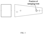
- FIG. 3 shows a schematic diagram of a sampling position in a deep hole of a reactor graphite block.
- FIG. 4 shows a schematic diagram of a sampling position in a reactor graphite block.
- FIG. 3 and FIG. 4 show the position of the sampling hole.
- a sampling device of acquiring a graphite sample from a reactor graphite block includes a support, a lifter, and a sampling actuator.
- the support is placed on the reactor graphite block.
- a graphite sidewall sampling machine 10 is placed on a reactor graphite block 11.
- the lifter may be, for example but not limitation, a lifting and rotating mechanism for sampling 3 shown in FIG. 5 .
- the lifter may be inserted into the reactor graphite block in a first direction.
- the sampling actuator is arranged at an end of the lifter and is used to acquire a graphite sample from the reactor graphite block.
- the sampling actuator may be inserted into the reactor graphite block in a second direction, and the first direction is substantially perpendicular to the second direction.
- the first direction is a direction in which the graphite sidewall sampling machine 10 rises and falls in the reactor graphite block 11
- the second direction is a direction in which the sampling actuator feeds in the reactor graphite block 11.
- a caster is installed at a bottom of the support to move the support on the reactor graphite block, so that the lifter is aligned with a sampling position of the reactor graphite block.
- the sampling position is a vertical through hole of the reactor graphite block, and the lifter is movable up and down in the vertical through hole of the reactor graphite block in the first direction.
- the support may further include: a lifting fixed holder 2 fixed on an upper part of the support 1; a guide rail arranged on the lifting fixed holder 2, and the lifter being movable on the guide rail in the first direction; and a locking device used to lock the lifter on the guide rail.
- the lifter may include: a lifting rod that may be, by way of example but not limitation, a sampling operation rod 4 shown in FIG. 5 .
- the lifting rod may be inserted into the reactor graphite block in the first direction from the sampling position of the reactor graphite block.
- the lifting rod is a telescopic rod including a plurality of segments that are extendable and retractable in the first direction.
- Each of the plurality of segments may include: a mandrel arranged at a center of the telescopic rod; and a sleeve arranged around the mandrel on a periphery of the mandrel.
- the mandrel is extendable and retractable in the first direction to reach a desired length of the telescopic rod.
- the mandrel may be driven hydraulically or electrically.
- the sampling actuator 5 is installed at a bottom of the lifting rod, and a sampling operation wheel 6, for example, a manual sampling operation wheel 6, is installed at a top of the lifting rod and is used to actuate the sampling actuator.
- a sampling operation wheel 6 for example, a manual sampling operation wheel 6, is installed at a top of the lifting rod and is used to actuate the sampling actuator.
- the sampling operation wheel may also be driven electrically.
- a turn counter is installed on an upper part of the sampling operation wheel so as to record a feeding depth of the sampling actuator.
- the lifter may include a clamping mechanism and a rotating mechanism.
- the clamping mechanism is used to clamp the telescopic rod.
- the clamping mechanism may include a clamping wheel, a clamping mechanism reducer and a clamping mechanism servo motor.
- the rotating mechanism is used to drive, by rotation, the telescopic rod to move in the first direction.
- the rotating mechanism may include a gear, a rotating mechanism reducer and a rotating mechanism servo motor.
- the sampling actuator includes: a connecting sleeve 5-1 for connecting the sampling actuator 5 to the lifter; a transmission shaft 5-4 arranged in the connecting sleeve 5-1 and used to transmit a rotating power; and a rotary drill 5-11 that may rotate and travel in the second direction so as to cut graphite around the graphite sample 12.
- At least one cutting blade for example but not limitation, a sampling knife 5-12 shown in FIG. 7 , is arranged on an outer circumference of the rotary drill 5-11.
- the transmission shaft may transmit rotating power so that the rotary drill moves between a feeding state and a cutting state.
- the rotary drill rotates forward, and a cutting cam 5-14 follows the rotary drill and rotates in close contact with the graphite sample.
- the rotary drill rotates reversely and applies a radial force toward the graphite sample so as to cut off the graphite sample from the reactor graphite block.
- a cutting cam 5-14 is provided at an end of the rotary drill and is used to cut off the graphite sample from the reactor graphite block.
- the cutting cam is fixed on the rotary drill through a fixing pin 5-15, and the cutting cam 5-14 may move reversely with the rotary drill with the fixing pin 5-15 as a center.
- the cutting cam 5-14 rotates, a linear distance between a bonding surface of the cutting cam with the graphite sample and the fixing pin increases, so that the cutting cam applies a radial force toward the graphite sample to cut off the graphite sample.
- the rotary drill 5-11 is a hollow structure with a hollow inner cavity, and the graphite sample 12 cut off falls into the inner cavity of the rotary drill 5-11.
- the cutting cam is provided with a tooth surface on a side close to the graphite sample.
- a dimension of the cutting cam is set to prevent the graphite sample from falling out of the inner cavity of the rotary drill.
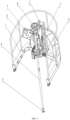
- the sampling device 10 is a sampling device of remotely sampling in a reactor graphite deep hole, which may be, for example, a graphite sidewall sampling device 10 shown in FIG. 5 .
- the graphite sidewall sampling device 10 may include: a fixed support 1, a lifting fixed holder 2, a lifting and rotating mechanism for sampling 3, a sampling operation rod 4, a sampling actuator 5, a manual sampling operation wheel 6, an operation control panel 7, a safety fence 8 and a distribution box 9.
- a caster is installed at the bottom of the fixed support 1 to facilitate the movement of the sampling device 10 and the alignment with the sampling hole.
- the lifting fixed holder 2 is welded to the upper part of the fixed support 1.
- the lifting and rotating mechanism for sampling 3 is installed on the lifting fixed holder 2 through the guide rail and the locking device, and may move up and down along the guide rail.
- a sampling operation rod clamping mechanism and a rotating mechanism are installed on the lifting and rotating mechanism for sampling 3.
- the sampling operation rod clamping mechanism includes a clamping wheel, a reducer and a servo motor.
- the rotating mechanism includes a gear, a reducer, and a servo motor.
- the sampling operation rod 4 includes a plurality of segments of stainless steel tubes and mandrels.
- a sampling actuator 5 is installed at the bottom of the sampling operation rod 4, and a manual sampling operation wheel 6 is installed at the top of the sampling operation rod 4.
- a length of the sampling operation rod 4 is determined by a number of the segments.
- the sampling actuator 5 is used for the sampling operation on the sidewall of the graphite 11.
- the manual sampling operation wheel 6 is used to provide a driving force for the sampling on the sidewall of the graphite 11.
- a turn counter is installed on the upper part of the manual sampling operation wheel 6 to record a feeding depth of the sampling actuator 5.
- a button provided on the operation control panel 7 may be operated to control the lifting and rotating of the sampling operation rod 4.
- the safety fence 8 is formed by welding conventional steel pipes to prevent unrelated persons from approaching the operating position.
- the distribution box 9 is used to install a servo motor controller and other electrical components.
- the sampling actuator 5 is a key component of the device, and the overall design is shown in FIG. 7 . Main functions of various components of the actuator are described as follows.
- the connecting sleeve 5-1 is connected with the sampling operation rod 4 in FIG. 5 ;
- a upper fixed seat 5-2 and the connecting sleeve 5-1 are fixed by a bolt;
- a lower fixed seat 5-3 is also fixed to the upper fixed seat 5-2 with a bolt; the upper fixed seat 5-2 and the lower fixed seat 5-3 simultaneously fix the rotary sampling device.
- the transmission shaft 5-4 transmits the upper rotating power to the rotary drill 5-11, and is connected with a driving helical gear 5-6 through a bolt;
- a bearing 5-5 includes a pair of angular contact bearings to prevent the transmission shaft 5-4 from moving up and down;
- the driven helical gear 5-7 is a welded part formed by welding a spline sleeve and a helical gear and is used to transmit the power of the driving helical gear 5-6 to the screw 5-10;
- the screw 5-10 is fixed to the fixed support 5-13, and an outer circumference of the screw 5-10 is processed into a special pitch external thread;
- a bearing 5-8 and a bearing 5-9 fix the driven helical gear 5-7 in the radial direction;
- the outer circumference of the rotary drill 5-11 is processed with a spline matching with the spline sleeve, and the inner circumference is processed into an internal thread that matches the special external thread of the screw 5-10, and the top is
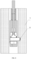
- a set of cutting cams are designed in the present disclosure, as shown in FIG. 8 to FIG. 9 .
- the rotary drill 5-11 rotates, and the cutting cam 5-14 follows the rotary drill 5-11 and rotates in close contact with the graphite sample 12. After a certain number of rotations, the cutting cam reaches the cutting state.
- the rotary drill 5-11 rotates reversely.
- the cutting cam 5-14 is provided with a specially designed tooth surface on a side of the cutting cam 5-14 closely attached to the graphite sample 12, and the cutting cam 5-14 follows the rotary drill 5-11 to move reversely with the fixing pin 5-15 as the center.
- FIG. 6 shows an operating state of the graphite sidewall sampling device after it is installed in place.
- the graphite sidewall sampling device 10 is moved to above the graphite 11.
- the graphite sidewall sampling device 10 is fixed when it is observed that the sampling actuator 5 is aligned with the sampling hole on the graphite.
- a sampling depth and a sampling direction are set on the operation control panel 7.
- a down button is pressed.
- the sampling actuator 5 reaches a specified depth, a manual operation is performed so that the manual sampling operation wheel 6 rotates for a specified number of turns, and then rotates reversely for the same number of turns.
- an up button on the operation control panel 7 is pressed.
- the graphite sample may be taken out.
- the graphite sidewall sampling device 10 is operated as follows.
- the connecting sleeve 5-1 is connected with the sampling operation rod 4; the transmission shaft 5-4 is rotated to transmit a power to the driving helical gear 5-6, the driving helical gear 5-6 transmits the power to the driven helical gear 5-7, and the driven helical gear 5-7 drives, through the spline, the rotary drill 5 to rotate, and at the same time, the rotary drill 5-11 moves axially through the screw 5-10 to realize the feeding of the rotary drill 5-11; the sampling knife 5-12 on the top of the rotary drill 5-11 cuts the graphite around the graphite sample 12, and when the transmission shaft 5-4 rotates for a certain number of turns, the rotary drill 5-11 reaches a maximum stroke and stops feeding; then, the rotary drill 5-11 starts to rotate reversely, and the rotary drill 5-11 starts to return.
- the cutting cam 5-14 installed on the top of the rotary drill 5-11 cuts off the graphite sample 12 under the action of the reverse force, and prevents the graphite sample 12 from falling out of the inner cavity of the rotary drill 5-11.
- the rotary drill 5-11 After the transmission shaft 5-4 rotates reversely for the same number of turns, the rotary drill 5-11 returns to an original position. The graphite sidewall sampling device 10 is lifted, and the graphite sample 12 may be taken out.
Landscapes
- Physics & Mathematics (AREA)
- Health & Medical Sciences (AREA)
- Life Sciences & Earth Sciences (AREA)
- Chemical & Material Sciences (AREA)
- Analytical Chemistry (AREA)
- Biochemistry (AREA)
- General Health & Medical Sciences (AREA)
- General Physics & Mathematics (AREA)
- Immunology (AREA)
- Pathology (AREA)
- Engineering & Computer Science (AREA)
- Plasma & Fusion (AREA)
- General Engineering & Computer Science (AREA)
- High Energy & Nuclear Physics (AREA)
- Sampling And Sample Adjustment (AREA)
Claims (15)
- Dispositif d'échantillonnage (10) pour acquérir un échantillon de graphite d'un bloc de graphite de réacteur (11) comprenant :un support (1) placé sur le bloc de graphite de réacteur (11) ;un dispositif de levage configuré pour être inséré dans le bloc de graphite de réacteur (11) dans une première direction ; etun actionneur d'échantillonnage (5) agencé à une extrémité du dispositif de levage et configuré pour acquérir un échantillon de graphite (12) du bloc de graphite de réacteur (11),dans lequel l'actionneur d'échantillonnage (5) est configuré pour s'insérer dans le bloc de graphite de réacteur (11) dans une seconde direction, et la première direction est sensiblement perpendiculaire à la seconde direction, etdans lequel l'actionneur d'échantillonnage (5) comprend :un manchon de raccordement (5-1) configuré pour raccorder l'actionneur d'échantillonnage (5) au dispositif de levage ;un arbre de transmission (5-4) agencé dans le manchon de raccordement (5-1) et configuré pour transmettre une puissance de rotation ; etun foret rotatif (5-11) configuré pour pouvoir tourner et se déplacer dans la seconde direction, etdans lequel l'arbre de transmission (5-4) est configuré pour transmettre la puissance de rotation de sorte que le foret rotatif (5-11) se déplace entre un état d'alimentation et un état de coupe, et à l'état d'alimentation, le foret rotatif (5-11) tourne vers l'avant, et à l'état de coupe, le foret rotatif (5-11) tourne en sens inverse et applique une force radiale vers l'échantillon de graphite (12), afin de couper l'échantillon de graphite (12) du bloc de graphite de réacteur (11), etcaractérisé en ce que :une came de coupe (5-14) est prévue au niveau d'une extrémité du foret rotatif (5-11), la came de coupe (5-14) est fixée sur le foret rotatif (5-11) par une broche de fixation (5-15) et est configurée pour couper l'échantillon de graphite (12) du bloc de graphite de réacteur (11), etdans lequel en réponse à la rotation vers l'avant du foret rotatif (5-11), la came de coupe (5-14) suit le foret rotatif (5-11) et tourne en contact immédiat avec l'échantillon de graphite (12) ;en réponse à la rotation en sens inverse du foret rotatif (5-11), la came de coupe (5-14) se déplace en sens inverse avec le foret rotatif (5-11), avec la broche de fixation (5-15) en tant que centre ; etune distance linéaire entre une surface de liaison de la came de coupe (5-14) avec l'échantillon de graphite (12) et la broche de fixation (5-15) augmente avec la rotation de la came de coupe (5-14), de sorte que la came de coupe (5-14) applique une force radiale vers l'échantillon de graphite (12) pour couper l'échantillon de graphite (12).
- Dispositif d'échantillonnage (10) selon la revendication 1, dans lequel une roulette est installée au fond du support (1) pour déplacer le support (1) sur le bloc de graphite de réacteur (11), de sorte que le dispositif de levage est aligné avec une position d'échantillonnage du bloc de graphite de réacteur (11).
- Dispositif d'échantillonnage (10) selon la revendication 2, dans lequel la position d'échantillonnage est un trou débouchant vertical du bloc de graphite de réacteur (11) et le dispositif de levage est configuré pour pouvoir se déplacer vers le haut et vers le bas dans le trou débouchant vertical du bloc de graphite de réacteur (11) dans la première direction.
- Dispositif d'échantillonnage (10) selon la revendication 1, dans lequel le support (1) comprend en outre :un support fixe de levage (2) fixé sur une partie supérieure du support (1) ;un rail de guidage agencé sur le support fixe de levage (2), dans lequel le dispositif de levage est configuré pour être mobile sur le rail de guidage dans la première direction ; etun dispositif de blocage configuré pour bloquer le dispositif de levage sur le rail de guidage.
- Dispositif d'échantillonnage (10) selon la revendication 1, dans lequel le dispositif de levage comprend :
une tige de levage configurée pour s'insérer dans le bloc de graphite de réacteur (11) dans la première direction à partir d'une position d'échantillonnage du bloc de graphite de réacteur (11) . - Dispositif d'échantillonnage (10) selon la revendication 5, dans lequel la tige de levage est une tige télescopique comprenant une pluralité de segments qui sont extensibles et rétractiles dans la première direction ;
dans lequel chacun de la pluralité de segments comprend :un mandrin agencé au niveau d'un centre de la tige télescopique ; etun manchon agencé autour du mandrin sur une périphérie du mandrin,dans lequel le mandrin est configuré pour s'étendre et se rétracter dans la première direction pour atteindre une longueur souhaitée de la tige télescopique. - Dispositif d'échantillonnage (10) selon la revendication 5, dans lequel l'actionneur d'échantillonnage (5) est installé au fond de la tige de levage, et une roue d'actionnement d'échantillonnage (6) est installée en haut de la tige de levage pour actionner l'actionneur d'échantillonnage (5) ;
dans lequel un compte-tour est installé sur une partie supérieure de la roue d'actionnement d'échantillonnage (6) afin d'enregistrer une profondeur d'alimentation de l'actionneur d'échantillonnage (5). - Dispositif d'échantillonnage (10) selon la revendication 1, dans lequel le dispositif de levage comprend :un mécanisme de serrage configuré pour serrer la tige télescopique ; etun mécanisme de rotation configuré pour entraîner, par rotation, la tige télescopique à se déplacer dans la première direction ;dans lequel le mécanisme de serrage comprend une roue de serrage, un réducteur de mécanisme de serrage et un servo-moteur de mécanisme de serrage ; et le mécanisme de rotation comprend un engrenage, un réducteur de mécanisme de rotation et un servo-moteur de mécanisme de rotation.
- Dispositif d'échantillonnage (10) selon la revendication 1, dans lequel le foret rotatif (5-11) est configuré pour couper le graphite autour de l'échantillon de graphite (12) ; ou bien
dans lequel au moins une lame de coupe est agencée sur une circonférence externe du foret rotatif (5-11). - Dispositif d'échantillonnage (10) selon la revendication 1, dans lequel le foret rotatif (5-11) est une structure creuse avec une cavité interne creuse, et l'échantillon de graphite coupé (12) tombe dans la cavité interne du foret rotatif (5-11).
- Dispositif d'échantillonnage (10) selon la revendication 1, dans lequel la came de coupe (5-14) est prévue avec une surface de dent d'un côté de la came de coupe (5-14) en contact immédiat avec l'échantillon de graphite (12) ;
dans lequel une dimension de la came de coupe (5-14) est réglée pour empêcher l'échantillon de graphite (12) de tomber de la cavité interne du foret rotatif (5-11). - Appareil pour mesurer une radioactivité de graphite, comprenant :le dispositif d'échantillonnage (10) selon les revendications 1 à 11, dans lequel le dispositif d'échantillonnage (10) est configuré pour acquérir un échantillon de graphite ;un dispositif de distribution d'échantillon pour distribuer l'échantillon acquis par le dispositif d'échantillonnage (10) à un dispositif de préparation d'échantillon ; etle dispositif de préparation d'échantillon configuré pour recevoir et traiter l'échantillon depuis le dispositif de distribution d'échantillon.
- Appareil pour mesurer la radioactivité de graphite selon la revendication 12, comprenant :
une unité d'analyse et de détection, dans lequel le dispositif d'échantillonnage (10) est agencé dans l'unité d'analyse et de détection. - Procédé d'échantillonnage pour acquérir un échantillon d'un graphite en utilisant le dispositif d'échantillonnage (10) selon l'une quelconque des revendications 1 à 11, comprenant les étapes consistant à :déplacer le dispositif d'échantillonnage (10) au-dessus du graphite ;fixer le dispositif d'échantillonnage (10) en réponse au fait d'avoir observé que le dispositif d'échantillonnage (10) est aligné avec un trou d'échantillonnage sur le graphite ;insérer le dispositif de levage du dispositif d'échantillonnage (10) dans le trou d'échantillonnage dans la première direction jusqu'à ce que le dispositif d'échantillonnage (10) atteigne une profondeur ; etinsérer l'actionneur d'échantillonnage (5) agencé à une extrémité du dispositif de levage dans le graphite dans la seconde direction, dans lequel la première direction est sensiblement perpendiculaire à la seconde direction, le procédé comprenant en outre l'étape consistant à :déplacer l'actionneur d'échantillonnage (5) entre un état d'alimentation et un état de coupe, dans lequel à l'état d'alimentation, l'actionneur d'échantillonnage (5) tourne vers l'avant, et à l'état de coupe, l'actionneur d'échantillonnage (5) tourne en sens inverse et applique une force radiale vers l'échantillon, afin de couper l'échantillon du graphite,dans lequel la came de coupe (5-14) est prévue à une extrémité de l'actionneur d'échantillonnage (5) ;en réponse à la rotation vers l'avant de l'actionneur d'échantillonnage (5), la came de coupe (5-14) suit l'actionneur d'échantillonnage (5) et tourne en contact immédiat avec l'échantillon de graphite (12) ;en réponse à la rotation en sens inverse de l'actionneur d'échantillonnage (5), la came de coupe (5-14) se déplace en sens inverse avec l'actionneur d'échantillonnage (5) ; etavec la rotation de la came de coupe (5-14), la came de coupe (5-14) applique une force radiale vers l'échantillon afin de couper l'échantillon du graphite.
- Procédé d'échantillonnage selon la revendication 14, dans lequel l'actionneur d'échantillonnage (5) comprend une cavité interne creuse, et l'échantillon coupé tombe dans la cavité interne de l'actionneur d'échantillonnage (5) ;
le procédé d'échantillonnage comprenant en outre l'étape consistant à :faire tourner l'actionneur d'échantillonnage (5) de sorte que l'actionneur d'échantillonnage (5) se rétracte dans le dispositif de levage du dispositif d'échantillonnage (10) ;le procédé d'échantillonnage comprenant en outre l'étape consistant à lever le dispositif de levage du dispositif d'échantillonnage au-dessus du graphite afin de prélever l'échantillon.
Applications Claiming Priority (2)
| Application Number | Priority Date | Filing Date | Title |
|---|---|---|---|
| CN202011609836.3A CN112557092B (zh) | 2020-12-29 | 2020-12-29 | 取样装置 |
| PCT/CN2021/098807 WO2022142140A1 (fr) | 2020-12-29 | 2021-06-08 | Dispositif de mesure de radioactivité de graphite, appareil d'échantillonnage et procédé d'échantillonnage |
Publications (3)
| Publication Number | Publication Date |
|---|---|
| EP4043857A1 EP4043857A1 (fr) | 2022-08-17 |
| EP4043857A4 EP4043857A4 (fr) | 2023-01-25 |
| EP4043857B1 true EP4043857B1 (fr) | 2023-08-09 |
Family
ID=75034614
Family Applications (1)
| Application Number | Title | Priority Date | Filing Date |
|---|---|---|---|
| EP21759225.2A Active EP4043857B1 (fr) | 2020-12-29 | 2021-06-08 | Dispositif de mesure de radioactivité de graphite, appareil d'échantillonnage et procédé d'échantillonnage |
Country Status (4)
| Country | Link |
|---|---|
| US (1) | US12405188B2 (fr) |
| EP (1) | EP4043857B1 (fr) |
| CN (1) | CN112557092B (fr) |
| WO (1) | WO2022142140A1 (fr) |
Families Citing this family (4)
| Publication number | Priority date | Publication date | Assignee | Title |
|---|---|---|---|---|
| CN112151200B (zh) * | 2020-08-20 | 2023-01-10 | 中国原子能科学研究院 | 一种放射性石墨深孔远距离取样系统 |
| CN112557092B (zh) | 2020-12-29 | 2022-08-09 | 中国原子能科学研究院 | 取样装置 |
| CN116213009B (zh) * | 2023-03-04 | 2025-09-19 | 湖南大学 | 一种石墨反应堆退役用废石墨块拆除方法 |
| CN116907915B (zh) * | 2023-09-14 | 2023-12-12 | 广东禹航环境科技有限公司 | 一种用于土壤污染治理的土壤取样设备 |
Family Cites Families (26)
| Publication number | Priority date | Publication date | Assignee | Title |
|---|---|---|---|---|
| FR1508238A (fr) * | 1966-11-21 | 1968-01-05 | Commissariat Energie Atomique | Appareil de travail à distance dans un tube |
| AR016883A1 (es) * | 1997-08-28 | 2001-08-01 | Shell Int Research | Un trepano rotativo para perforar |
| DE19811699A1 (de) * | 1998-03-10 | 1999-09-16 | Martin Honold | Modulare Sonde |
| JP4081452B2 (ja) | 2004-02-24 | 2008-04-23 | 独立行政法人海洋研究開発機構 | 地殻コア試料の採取方法 |
| US8171808B2 (en) * | 2008-05-02 | 2012-05-08 | Johnson Industries, Inc. | Material sampling device with rotatable tube assembly |
| RU2378510C1 (ru) * | 2008-07-01 | 2010-01-10 | Открытое акционерное общество "Сибирский химический комбинат" (ОАО "СХК") | Устройство горизонтального выбуривания кернов из стенок скважин или каналов |
| US20140131165A1 (en) * | 2012-11-14 | 2014-05-15 | Johnson Industries, Inc. | Material sampling device with integrated material analyzer assembly |
| CN204789019U (zh) | 2015-06-12 | 2015-11-18 | 中钢集团邢台机械轧辊有限公司 | 一种深盲孔芯棒的切断刀片 |
| RU2618214C1 (ru) * | 2016-04-27 | 2017-05-03 | Акционерное общество Опытно-демонстрационный центр вывода из эксплуатации уран-графитовых ядерных реакторов | Устройство для локального выбуривания участков графитовых колонн кладки реактора |
| CN205614855U (zh) * | 2016-05-18 | 2016-10-05 | 大同新成新材料股份有限公司 | 一种石墨产品取样的钻孔装置 |
| CN106246124A (zh) * | 2016-07-29 | 2016-12-21 | 中国石油天然气股份有限公司 | 井下检测系统及其方法 |
| CN107829699A (zh) * | 2017-10-26 | 2018-03-23 | 西南石油大学 | 一种磨削式防掉岩石取样装置及使用方法 |
| CN108119081A (zh) * | 2018-02-28 | 2018-06-05 | 山东科技大学 | 一种新型岩石取样专用水钻钻头 |
| CN209040753U (zh) | 2018-08-23 | 2019-06-28 | 中交隧道工程局有限公司 | 一种具备截断齿的牙轮筒钻 |
| CN209148339U (zh) * | 2018-11-30 | 2019-07-23 | 重庆工程职业技术学院 | 地质土壤采集装置 |
| CN109752209A (zh) * | 2018-12-30 | 2019-05-14 | 孙浩宁 | 土壤采样装置 |
| CN209432492U (zh) * | 2019-01-09 | 2019-09-24 | 郑州汇之丰科技有限公司 | 一种取样方便的土壤采样钻机 |
| CN110398389A (zh) | 2019-06-18 | 2019-11-01 | 毕海民 | 一种岩土工程勘察用岩土取样装置 |
| JP6618135B1 (ja) * | 2019-07-11 | 2019-12-11 | 千葉エンジニアリング株式会社 | サンプラー |
| CN211085716U (zh) * | 2019-07-25 | 2020-07-24 | 徐州天艺制盖有限公司 | 一种便于石油地质取样检测的钻孔装置 |
| CN211477679U (zh) * | 2019-12-19 | 2020-09-11 | 广东天人不动产测绘规划有限公司 | 一种地质测绘用取样装置 |
| CN111351681B (zh) * | 2020-03-16 | 2023-01-06 | 东华理工大学 | 一种土木工程用岩土取样机械装置 |
| CN211825141U (zh) * | 2020-03-25 | 2020-10-30 | 刘志军 | 一种岩土工程勘探快速取样装置 |
| CN111350500A (zh) * | 2020-04-14 | 2020-06-30 | 孟丽杰 | 一种用于地质勘探的土样采集器 |
| US11948700B2 (en) * | 2020-11-11 | 2024-04-02 | Grant Charters | In-situ method of drilling to collect dry samples from a nuclear reactor core interior for analysis |
| CN112557092B (zh) | 2020-12-29 | 2022-08-09 | 中国原子能科学研究院 | 取样装置 |
-
2020
- 2020-12-29 CN CN202011609836.3A patent/CN112557092B/zh active Active
-
2021
- 2021-06-08 EP EP21759225.2A patent/EP4043857B1/fr active Active
- 2021-06-08 US US17/436,458 patent/US12405188B2/en active Active
- 2021-06-08 WO PCT/CN2021/098807 patent/WO2022142140A1/fr not_active Ceased
Also Published As
| Publication number | Publication date |
|---|---|
| CN112557092B (zh) | 2022-08-09 |
| WO2022142140A1 (fr) | 2022-07-07 |
| EP4043857A4 (fr) | 2023-01-25 |
| CN112557092A (zh) | 2021-03-26 |
| EP4043857A1 (fr) | 2022-08-17 |
| US12405188B2 (en) | 2025-09-02 |
| US20250044195A1 (en) | 2025-02-06 |
Similar Documents
| Publication | Publication Date | Title |
|---|---|---|
| EP4043857B1 (fr) | Dispositif de mesure de radioactivité de graphite, appareil d'échantillonnage et procédé d'échantillonnage | |
| US6599067B2 (en) | Apparatus for removing pressure tubes | |
| US4682725A (en) | Process of replacing a sleeve mounted within a pipe | |
| JP6700524B2 (ja) | コアドリルと穿孔方法 | |
| US3513517A (en) | Machining of large hollow cylindrical workpieces | |
| CN109454677B (zh) | 一种模块化线缆切削机床 | |
| CN115184073A (zh) | 岩土工程用岩芯取样装置 | |
| CN117030336B (zh) | 一种土壤修复地深处样本采样无人机 | |
| CA1240491A (fr) | Dispositif de doublage de tubes en milieu agressif | |
| WO1984000709A1 (fr) | Outil portatif d'usinage d'extremites de tubes | |
| CN111360314B (zh) | 一种切割装置 | |
| CN114619278B (zh) | 一种减速器输出法兰高精度加工设备及加工工艺 | |
| US5238338A (en) | Machining device operating inside a canalization | |
| CN115012827B (zh) | 一种桩基井扩孔装置 | |
| CN220378232U (zh) | 闭环联控式井下电动切割工具 | |
| CN110142434B (zh) | 一种具有预处理的高效玻璃充电式电钻 | |
| JP4777167B2 (ja) | ロックボルト用穿孔装置およびロックボルト用孔の穿孔方法 | |
| KR101461377B1 (ko) | 이동형 보링머신 | |
| RU2618214C1 (ru) | Устройство для локального выбуривания участков графитовых колонн кладки реактора | |
| CN116124507A (zh) | 一种用于混凝土试块芯样钻取的多轴钻机架 | |
| RU2454536C2 (ru) | Устройство выбуривания кернов из стенок скважин или каналов | |
| CN212337172U (zh) | 一种岩土工程勘察用钻探装置 | |
| CN222904529U (zh) | 一种岩芯切割机 | |
| RU2858983C1 (ru) | Устройство отбора проб из графитовых блоков | |
| US1678307A (en) | Earth-boring machine |
Legal Events
| Date | Code | Title | Description |
|---|---|---|---|
| STAA | Information on the status of an ep patent application or granted ep patent |
Free format text: STATUS: UNKNOWN |
|
| STAA | Information on the status of an ep patent application or granted ep patent |
Free format text: STATUS: THE INTERNATIONAL PUBLICATION HAS BEEN MADE |
|
| PUAI | Public reference made under article 153(3) epc to a published international application that has entered the european phase |
Free format text: ORIGINAL CODE: 0009012 |
|
| STAA | Information on the status of an ep patent application or granted ep patent |
Free format text: STATUS: REQUEST FOR EXAMINATION WAS MADE |
|
| 17P | Request for examination filed |
Effective date: 20210903 |
|
| AK | Designated contracting states |
Kind code of ref document: A1 Designated state(s): AL AT BE BG CH CY CZ DE DK EE ES FI FR GB GR HR HU IE IS IT LI LT LU LV MC MK MT NL NO PL PT RO RS SE SI SK SM TR |
|
| A4 | Supplementary search report drawn up and despatched |
Effective date: 20230103 |
|
| RIC1 | Information provided on ipc code assigned before grant |
Ipc: G21C 17/00 20060101ALI20221221BHEP Ipc: G01N 1/08 20060101AFI20221221BHEP |
|
| GRAP | Despatch of communication of intention to grant a patent |
Free format text: ORIGINAL CODE: EPIDOSNIGR1 |
|
| STAA | Information on the status of an ep patent application or granted ep patent |
Free format text: STATUS: GRANT OF PATENT IS INTENDED |
|
| DAV | Request for validation of the european patent (deleted) | ||
| DAX | Request for extension of the european patent (deleted) | ||
| INTG | Intention to grant announced |
Effective date: 20230317 |
|
| GRAS | Grant fee paid |
Free format text: ORIGINAL CODE: EPIDOSNIGR3 |
|
| GRAA | (expected) grant |
Free format text: ORIGINAL CODE: 0009210 |
|
| STAA | Information on the status of an ep patent application or granted ep patent |
Free format text: STATUS: THE PATENT HAS BEEN GRANTED |
|
| AK | Designated contracting states |
Kind code of ref document: B1 Designated state(s): AL AT BE BG CH CY CZ DE DK EE ES FI FR GB GR HR HU IE IS IT LI LT LU LV MC MK MT NL NO PL PT RO RS SE SI SK SM TR |
|
| REG | Reference to a national code |
Ref country code: GB Ref legal event code: FG4D |
|
| REG | Reference to a national code |
Ref country code: CH Ref legal event code: EP |
|
| REG | Reference to a national code |
Ref country code: IE Ref legal event code: FG4D |
|
| REG | Reference to a national code |
Ref country code: DE Ref legal event code: R096 Ref document number: 602021004188 Country of ref document: DE |
|
| REG | Reference to a national code |
Ref country code: LT Ref legal event code: MG9D |
|
| REG | Reference to a national code |
Ref country code: NL Ref legal event code: MP Effective date: 20230809 |
|
| REG | Reference to a national code |
Ref country code: AT Ref legal event code: MK05 Ref document number: 1598048 Country of ref document: AT Kind code of ref document: T Effective date: 20230809 |
|
| PG25 | Lapsed in a contracting state [announced via postgrant information from national office to epo] |
Ref country code: GR Free format text: LAPSE BECAUSE OF FAILURE TO SUBMIT A TRANSLATION OF THE DESCRIPTION OR TO PAY THE FEE WITHIN THE PRESCRIBED TIME-LIMIT Effective date: 20231110 |
|
| PG25 | Lapsed in a contracting state [announced via postgrant information from national office to epo] |
Ref country code: IS Free format text: LAPSE BECAUSE OF FAILURE TO SUBMIT A TRANSLATION OF THE DESCRIPTION OR TO PAY THE FEE WITHIN THE PRESCRIBED TIME-LIMIT Effective date: 20231209 |
|
| PG25 | Lapsed in a contracting state [announced via postgrant information from national office to epo] |
Ref country code: SE Free format text: LAPSE BECAUSE OF FAILURE TO SUBMIT A TRANSLATION OF THE DESCRIPTION OR TO PAY THE FEE WITHIN THE PRESCRIBED TIME-LIMIT Effective date: 20230809 Ref country code: RS Free format text: LAPSE BECAUSE OF FAILURE TO SUBMIT A TRANSLATION OF THE DESCRIPTION OR TO PAY THE FEE WITHIN THE PRESCRIBED TIME-LIMIT Effective date: 20230809 Ref country code: PT Free format text: LAPSE BECAUSE OF FAILURE TO SUBMIT A TRANSLATION OF THE DESCRIPTION OR TO PAY THE FEE WITHIN THE PRESCRIBED TIME-LIMIT Effective date: 20231211 Ref country code: NO Free format text: LAPSE BECAUSE OF FAILURE TO SUBMIT A TRANSLATION OF THE DESCRIPTION OR TO PAY THE FEE WITHIN THE PRESCRIBED TIME-LIMIT Effective date: 20231109 Ref country code: NL Free format text: LAPSE BECAUSE OF FAILURE TO SUBMIT A TRANSLATION OF THE DESCRIPTION OR TO PAY THE FEE WITHIN THE PRESCRIBED TIME-LIMIT Effective date: 20230809 Ref country code: LV Free format text: LAPSE BECAUSE OF FAILURE TO SUBMIT A TRANSLATION OF THE DESCRIPTION OR TO PAY THE FEE WITHIN THE PRESCRIBED TIME-LIMIT Effective date: 20230809 Ref country code: LT Free format text: LAPSE BECAUSE OF FAILURE TO SUBMIT A TRANSLATION OF THE DESCRIPTION OR TO PAY THE FEE WITHIN THE PRESCRIBED TIME-LIMIT Effective date: 20230809 Ref country code: IS Free format text: LAPSE BECAUSE OF FAILURE TO SUBMIT A TRANSLATION OF THE DESCRIPTION OR TO PAY THE FEE WITHIN THE PRESCRIBED TIME-LIMIT Effective date: 20231209 Ref country code: HR Free format text: LAPSE BECAUSE OF FAILURE TO SUBMIT A TRANSLATION OF THE DESCRIPTION OR TO PAY THE FEE WITHIN THE PRESCRIBED TIME-LIMIT Effective date: 20230809 Ref country code: GR Free format text: LAPSE BECAUSE OF FAILURE TO SUBMIT A TRANSLATION OF THE DESCRIPTION OR TO PAY THE FEE WITHIN THE PRESCRIBED TIME-LIMIT Effective date: 20231110 Ref country code: FI Free format text: LAPSE BECAUSE OF FAILURE TO SUBMIT A TRANSLATION OF THE DESCRIPTION OR TO PAY THE FEE WITHIN THE PRESCRIBED TIME-LIMIT Effective date: 20230809 Ref country code: AT Free format text: LAPSE BECAUSE OF FAILURE TO SUBMIT A TRANSLATION OF THE DESCRIPTION OR TO PAY THE FEE WITHIN THE PRESCRIBED TIME-LIMIT Effective date: 20230809 |
|
| PG25 | Lapsed in a contracting state [announced via postgrant information from national office to epo] |
Ref country code: PL Free format text: LAPSE BECAUSE OF FAILURE TO SUBMIT A TRANSLATION OF THE DESCRIPTION OR TO PAY THE FEE WITHIN THE PRESCRIBED TIME-LIMIT Effective date: 20230809 |
|
| PG25 | Lapsed in a contracting state [announced via postgrant information from national office to epo] |
Ref country code: ES Free format text: LAPSE BECAUSE OF FAILURE TO SUBMIT A TRANSLATION OF THE DESCRIPTION OR TO PAY THE FEE WITHIN THE PRESCRIBED TIME-LIMIT Effective date: 20230809 |
|
| PG25 | Lapsed in a contracting state [announced via postgrant information from national office to epo] |
Ref country code: SM Free format text: LAPSE BECAUSE OF FAILURE TO SUBMIT A TRANSLATION OF THE DESCRIPTION OR TO PAY THE FEE WITHIN THE PRESCRIBED TIME-LIMIT Effective date: 20230809 Ref country code: RO Free format text: LAPSE BECAUSE OF FAILURE TO SUBMIT A TRANSLATION OF THE DESCRIPTION OR TO PAY THE FEE WITHIN THE PRESCRIBED TIME-LIMIT Effective date: 20230809 Ref country code: ES Free format text: LAPSE BECAUSE OF FAILURE TO SUBMIT A TRANSLATION OF THE DESCRIPTION OR TO PAY THE FEE WITHIN THE PRESCRIBED TIME-LIMIT Effective date: 20230809 Ref country code: EE Free format text: LAPSE BECAUSE OF FAILURE TO SUBMIT A TRANSLATION OF THE DESCRIPTION OR TO PAY THE FEE WITHIN THE PRESCRIBED TIME-LIMIT Effective date: 20230809 Ref country code: DK Free format text: LAPSE BECAUSE OF FAILURE TO SUBMIT A TRANSLATION OF THE DESCRIPTION OR TO PAY THE FEE WITHIN THE PRESCRIBED TIME-LIMIT Effective date: 20230809 Ref country code: CZ Free format text: LAPSE BECAUSE OF FAILURE TO SUBMIT A TRANSLATION OF THE DESCRIPTION OR TO PAY THE FEE WITHIN THE PRESCRIBED TIME-LIMIT Effective date: 20230809 Ref country code: SK Free format text: LAPSE BECAUSE OF FAILURE TO SUBMIT A TRANSLATION OF THE DESCRIPTION OR TO PAY THE FEE WITHIN THE PRESCRIBED TIME-LIMIT Effective date: 20230809 |
|
| REG | Reference to a national code |
Ref country code: DE Ref legal event code: R097 Ref document number: 602021004188 Country of ref document: DE |
|
| PG25 | Lapsed in a contracting state [announced via postgrant information from national office to epo] |
Ref country code: IT Free format text: LAPSE BECAUSE OF FAILURE TO SUBMIT A TRANSLATION OF THE DESCRIPTION OR TO PAY THE FEE WITHIN THE PRESCRIBED TIME-LIMIT Effective date: 20230809 |
|
| PLBE | No opposition filed within time limit |
Free format text: ORIGINAL CODE: 0009261 |
|
| STAA | Information on the status of an ep patent application or granted ep patent |
Free format text: STATUS: NO OPPOSITION FILED WITHIN TIME LIMIT |
|
| 26N | No opposition filed |
Effective date: 20240513 |
|
| PG25 | Lapsed in a contracting state [announced via postgrant information from national office to epo] |
Ref country code: SI Free format text: LAPSE BECAUSE OF FAILURE TO SUBMIT A TRANSLATION OF THE DESCRIPTION OR TO PAY THE FEE WITHIN THE PRESCRIBED TIME-LIMIT Effective date: 20230809 |
|
| PG25 | Lapsed in a contracting state [announced via postgrant information from national office to epo] |
Ref country code: BG Free format text: LAPSE BECAUSE OF FAILURE TO SUBMIT A TRANSLATION OF THE DESCRIPTION OR TO PAY THE FEE WITHIN THE PRESCRIBED TIME-LIMIT Effective date: 20230809 |
|
| PG25 | Lapsed in a contracting state [announced via postgrant information from national office to epo] |
Ref country code: BG Free format text: LAPSE BECAUSE OF FAILURE TO SUBMIT A TRANSLATION OF THE DESCRIPTION OR TO PAY THE FEE WITHIN THE PRESCRIBED TIME-LIMIT Effective date: 20230809 |
|
| PG25 | Lapsed in a contracting state [announced via postgrant information from national office to epo] |
Ref country code: MC Free format text: LAPSE BECAUSE OF FAILURE TO SUBMIT A TRANSLATION OF THE DESCRIPTION OR TO PAY THE FEE WITHIN THE PRESCRIBED TIME-LIMIT Effective date: 20230809 |
|
| REG | Reference to a national code |
Ref country code: CH Ref legal event code: PL |
|
| PG25 | Lapsed in a contracting state [announced via postgrant information from national office to epo] |
Ref country code: LU Free format text: LAPSE BECAUSE OF NON-PAYMENT OF DUE FEES Effective date: 20240608 |
|
| PG25 | Lapsed in a contracting state [announced via postgrant information from national office to epo] |
Ref country code: IE Free format text: LAPSE BECAUSE OF NON-PAYMENT OF DUE FEES Effective date: 20240608 |
|
| PG25 | Lapsed in a contracting state [announced via postgrant information from national office to epo] |
Ref country code: BE Free format text: LAPSE BECAUSE OF NON-PAYMENT OF DUE FEES Effective date: 20240630 Ref country code: CH Free format text: LAPSE BECAUSE OF NON-PAYMENT OF DUE FEES Effective date: 20240630 |
|
| REG | Reference to a national code |
Ref country code: BE Ref legal event code: MM Effective date: 20240630 |
|
| PGFP | Annual fee paid to national office [announced via postgrant information from national office to epo] |
Ref country code: DE Payment date: 20250630 Year of fee payment: 5 |
|
| PGFP | Annual fee paid to national office [announced via postgrant information from national office to epo] |
Ref country code: GB Payment date: 20250621 Year of fee payment: 5 |
|
| PGFP | Annual fee paid to national office [announced via postgrant information from national office to epo] |
Ref country code: FR Payment date: 20250617 Year of fee payment: 5 |
|
| PG25 | Lapsed in a contracting state [announced via postgrant information from national office to epo] |
Ref country code: CY Free format text: LAPSE BECAUSE OF FAILURE TO SUBMIT A TRANSLATION OF THE DESCRIPTION OR TO PAY THE FEE WITHIN THE PRESCRIBED TIME-LIMIT; INVALID AB INITIO Effective date: 20210608 |
|
| PG25 | Lapsed in a contracting state [announced via postgrant information from national office to epo] |
Ref country code: HU Free format text: LAPSE BECAUSE OF FAILURE TO SUBMIT A TRANSLATION OF THE DESCRIPTION OR TO PAY THE FEE WITHIN THE PRESCRIBED TIME-LIMIT; INVALID AB INITIO Effective date: 20210608 |