EP4043859B1 - Dispositif de test et/ou d'essai - Google Patents
Dispositif de test et/ou d'essai Download PDFInfo
- Publication number
- EP4043859B1 EP4043859B1 EP22158670.4A EP22158670A EP4043859B1 EP 4043859 B1 EP4043859 B1 EP 4043859B1 EP 22158670 A EP22158670 A EP 22158670A EP 4043859 B1 EP4043859 B1 EP 4043859B1
- Authority
- EP
- European Patent Office
- Prior art keywords
- test
- inspected
- test object
- testing device
- tested
- Prior art date
- Legal status (The legal status is an assumption and is not a legal conclusion. Google has not performed a legal analysis and makes no representation as to the accuracy of the status listed.)
- Active
Links
Images

Classifications
-
- G—PHYSICS
- G01—MEASURING; TESTING
- G01N—INVESTIGATING OR ANALYSING MATERIALS BY DETERMINING THEIR CHEMICAL OR PHYSICAL PROPERTIES
- G01N3/00—Investigating strength properties of solid materials by application of mechanical stress
- G01N3/56—Investigating resistance to wear or abrasion
-
- G—PHYSICS
- G01—MEASURING; TESTING
- G01N—INVESTIGATING OR ANALYSING MATERIALS BY DETERMINING THEIR CHEMICAL OR PHYSICAL PROPERTIES
- G01N3/00—Investigating strength properties of solid materials by application of mechanical stress
- G01N3/40—Investigating hardness or rebound hardness
- G01N3/42—Investigating hardness or rebound hardness by performing impressions under a steady load by indentors, e.g. sphere, pyramid
- G01N3/46—Investigating hardness or rebound hardness by performing impressions under a steady load by indentors, e.g. sphere, pyramid the indentors performing a scratching movement
-
- G—PHYSICS
- G01—MEASURING; TESTING
- G01N—INVESTIGATING OR ANALYSING MATERIALS BY DETERMINING THEIR CHEMICAL OR PHYSICAL PROPERTIES
- G01N3/00—Investigating strength properties of solid materials by application of mechanical stress
- G01N3/40—Investigating hardness or rebound hardness
- G01N3/50—Investigating hardness or rebound hardness by measuring rolling friction, e.g. by rocking pendulum
Definitions
- the present invention relates to a testing device, in particular for testing and/or determining the resistance of surfaces or objects to abrasion or shock sensitivity or to scratch resistance.
- test devices are used to examine and evaluate various loads on objects in relation to impacts from another object.
- the object to be tested must be examined or evaluated to determine how it reacts to contact by any other body, e.g. use and/or operation with the fingers or hand, and after how many uses and/or contact cycles, such as operating processes, which signs of wear, such as abrasion, occur.
- test devices In the automotive industry, for example, tests must be carried out on control elements, fittings such as gearshift handles, upholstery, panels or painted surfaces such as trunk lids, hoods or door handles, which are touched and/or operated with hands, fingers or fingernails, but also other objects such as bags, clothing or keys.
- Known test devices test such surfaces in different ways and are designed as impact, shock, abrasion or scratch testers.
- a scratch tester for glass panes which uses a spring to exert an adjustable force on a cylinder, which in turn presses a diamond attached to it against the glass pane.
- the mechanism constructed in this way is pulled over the glass pane by means of sliding rails arranged on it on corresponding rails attached to the glass pane and a scratch is created on it. Based on the force exerted from above on the sliding block in order to bring the sliding rails to rest on the glass pane when the If the sliding block is moved over the glass surface, a test and/or inspection value of the scratch resistance is obtained.
- a device for testing the scratch resistance of surfaces is also used in the WO 2004/038385 A1
- the scratch resistance of a test specimen is tested using a gas flow mixed with solid particles.
- the resulting gas flow path is equipped with a dosing device, by means of which a defined amount of particles can be introduced into a specified gas flow, which act on the test object.
- Another scratch device or test device for the durability of a sample is used in the EN 10 2006 012 374 A1 described, with which a material sample, which is arranged on a movable table, is subjected to a load body which is pressed towards the sample holder with a weight. The sample holder is then moved with a predefined movement sequence in the (x, y) plane with an adjustable weight. The result of the material sample provides information about the resistance of the material sample to the applied load. Also well known is the so-called 3-body wear or the associated test, in which two bodies kept in motion with sand placed between them are rubbed against each other in order to obtain information about the abrasion resistance and/or friction properties. By choosing a medium other than sand, such as softer or harder materials or solid/liquid mixtures, different conditions can be set.
- a device for determining abrasion resistance is also known under the name "Linear Abraser".
- a test specimen which is adjustable in height and can be loaded with weights, is moved over an object to be tested, which can be used to make statements about the resistance of the test material to the back and forth movement over the test material.
- the drive is provided by a conventional electric motor, which drives a rod via a gear, which then moves almost linearly up and down, or rather back and forth, and to which the test device is attached.
- the electric motor and the The operating, control and display devices, as well as the gearbox and the linkage, are inseparably connected to one another as a unit.
- the known testing devices generally use either a movable table driven by at least one electric motor, on which the object to be tested is placed. A test object is then positioned on the object to be tested with a predetermined force, and the table on which the object to be tested is positioned is moved.
- the other known device uses an electric motor via a gear to drive a rod to which the test object is fixed in height.
- the device is designed as a complete unit, and the drive of either the object to be tested or the test object is implemented by an electric motor.
- the drive of either the object to be tested or the test object is implemented by an electric motor.
- a push rod driven by a gear which is additionally fixed in height and is not guided further outside the device, relatively inaccurate movement sequences can be seen.
- a further disadvantage is that the movements in the known designs only occur with low dynamics and low energy density.
- a device for testing a surface has a cylinder supported by supports.
- the cylinder has a rod connected to a sliding module supported by rails.
- the object of the present invention is therefore to provide a testing device for examining objects which reduces or eliminates the above-mentioned disadvantages. avoids.
- the object of the invention is to be able to test a large number of objects at different locations or specifically directly at the place of use and under many different conditions. For objects of everyday life, this also includes considerations of use and/or operation, for example by hand, which takes place very slowly and thus predetermines different contact with the object to be tested, such as dry or wet hands or taking into account various additional components such as cleaning agents, care products or similar substances.
- very highly dynamic processes, such as vibrations can also be examined and/or tested with the test device according to the invention. This also includes, for example, abrasion, scratches or other damage caused by, for example, hard objects on surfaces during vibrations.
- a testing device in particular for testing and/or determining the resistance of surfaces or objects to abrasion or impact sensitivity or scratch resistance, comprising an adaptive holding device or an access device to the object to be tested or a surface to be tested, at least one means for attaching a test object in front of or above the object to be tested, a device for moving the test object that strikes the object to be tested, and a control and Control device for controlling and monitoring the speed and force with which the test object comes into contact with the object to be tested, wherein the test device for the movement of the test object on the object to be tested is designed with a support device for the test object, which can be loaded with an additional weight and is equipped with a fluid-operated power cylinder or compressed air cylinder with a twist-proof, non-round push and pull rod, which is controlled via the control and monitoring device or can be connected to such a device and is attached at its end in a fastening so that it can rotate or at least incline.
- the pneumatic cylinder which is equipped with a non-round push and pull rod, is arranged so that it can rotate or at least tilt at its closed end directly or by means of a receiving device on a holding device.
- the position at which the pneumatic cylinder is attached to the holding device determines the base force or the weight that prevails at the end of the push and pull rod at a certain deflection.
- the holding device preferably allows the height adjustment of the end of the pneumatic cylinder to be accommodated in order to be able to react to different heights of test objects; alternatively, holders of different lengths can be used to adjust the height of the pneumatic cylinder to the height of the object to be tested, or to be able to initially bring it into a horizontal position.
- the pneumatic cylinder and/or the holding device for it has a leveling indicator, such as a small spirit level or an integrated and/or attached spirit level.
- the push and pull rod extending from the pneumatic cylinder is equipped at its end with a support device for the test object, whereby the support device is preferably designed to be rotatable, for example in order to To be able to adjust the angle of contact between the test object and the object to be tested.
- the test object is arranged at the end of a rod or bar, which is guided through the support device on the push and pull rod and can be fixed to it, e.g. by means of a locking screw. Additional weights can be arranged on the support device or along the rod or bar, at one end of which the test object is attached, in order to adjust the force with which the test object hits the object to be tested.
- the test device designed in this way allows the object to be tested to be loaded with the definable weight of the rocking part, the pneumatic cylinder arranged in the holder, the support device with the test object and the additional weight set by additional weights. Due to the selected design of a non-round push and pull rod and optionally also a non-round pneumatic cylinder, the position of the test object in relation to the object to be tested is very secure against twisting once it has been set and the push and pull rod does not need to be guided additionally. The device designed in this way also allows the test object to follow the contour and/or unevenness of the object to be tested, since the pneumatic cylinder is rotatably mounted at its end.
- the pneumatic cylinder is connected or can be connected to a control and monitoring device and a compressed air supply and allows very high dynamics and high forces in terms of the movement and speed with which the push and pull rod moves the test object over the object to be tested.
- the control system can also be used to set different speeds for each movement that can be varied over a wide range, which makes it easier to control objects with a preferred direction and/or objects in certain directions of movement. and can be tested and evaluated more precisely.
- the force or compressed air cylinder is also equipped with or connected to a pressure gauge and/or position and/or path measuring system connected to the control and monitoring device, with which the force and/or the path applied can be measured and, for example, is very easily available in a force-path diagram.
- the test device is also equipped with a force measuring device, such as a load cell below the object to be tested, with which, for example, stick-slip effects such as adhesion and/or jerk-slip effects of solid bodies moving against each other, e.g. creaking doors or rattling windshield wipers, can be examined and/or evaluated.
- a force measuring device such as a load cell below the object to be tested
- stick-slip effects such as adhesion and/or jerk-slip effects of solid bodies moving against each other, e.g. creaking doors or rattling windshield wipers
- the test device according to the invention can be used to carry out a wide variety of friction measurements and, for example, to test, examine and evaluate lubricants and/or oils in order to determine, for example, friction coefficients.
- the testing device In a preferred embodiment of the testing device according to the invention, it is designed on a base plate with a holding device for the object to be tested and a holding device for the pneumatic cylinder that is attached so that it can rotate and/or tilt. Additional holding and/or drive elements for the pneumatic cylinder can be provided on the base plate in order to be able to fix it at a predetermined inclination, for example, or to raise it at a point and lower it again.
- the holding device for the object to be tested can be pivoted, in particular pivoted or tilted by 90°, whereby the movement of the test object on the object to be tested can be either vertical or perpendicular to gravity.
- a web-like material is arranged in front of the object to be tested and between it and the test object acting on it. This The web-like material is preferably a fabric and/or textile, which is additionally exposed to a test liquid during the test. By selecting the material of the web-like medium and the test liquid accordingly, very different parameters can be achieved or simulated for the test.
- the surface of hands or special gloves can be simulated by means of appropriate roughness and it can be tested and/or checked and/or determined how often the object being tested can be loaded with which load from the test object under these conditions.
- appropriate liquids and/or lotions and/or other additives it can be tested and/or checked and/or determined, for example, how the objects to be tested behave when in contact with, for example, detergents, cleaners, other chemicals or substances.
- the numerous setting, adjustment and adaptation options of the test device mean that very realistic situations and/or situations from everyday life can be simulated under all conceivable external conditions and very meaningful and reliable findings can be obtained.
- the test device according to the invention can be used, for example, to simulate operations on a switch, keyboard or other control element with a hand or finger by a person.
- a switch, keyboard or other control element with a hand or finger by a person.
- contact with the fingers, hand or other surfaces or bodies can also be tested after adding a cleaning liquid or another fluid, cream or chemical.
- the test device is arranged in a further variant partially in a climate chamber.
- the control, monitoring and display device is preferably separated from the other components of the test device, arranged outside the climate chamber in order to protect electrical and/or electronic components and/or to maintain their function.
- the compressed air cylinder is equipped as required with a locally acting insulation and/or a heating device such as an applied heating foil, which is the control and monitoring device is controlled, which is located outside the climate chamber. This allows, for example, tests and/or examinations to be carried out at temperatures of up to minus 40° or below.
- the test device has a temperature sensor close to the object to be tested, which transmits the values to the control and monitoring device.
- the compressed air supplies for the compressed air cylinder which are fed from the compressed air supply and/or the control and monitoring device outside the climate chamber, are preferably insulated or designed with a trace heating system.
- the head of the test object can be varied in shape, size and hardness and is preferably designed to be interchangeable.
- different holders can be attached in order to be able to use very special objects as test objects, such as a key that comes into contact with the paint on the door handle or a textile surface or another surface.
- very special objects such as a key that comes into contact with the paint on the door handle or a textile surface or another surface.
- a head with a Shore hardness in the range of 40 to 50 has proven to be the preferred variant.
- the head is covered with a textile and/or absorbent material or is made of such a material.
- the head of the test object is equipped and/or covered with an at least partially absorbent material.
- the compressed air or power-operated cylinder is designed to be non-rotatable or to be fixable in a defined position.
- the compressed air-operated cylinder is equipped with at least one temperature sensor attached directly to it, which can be connected to the control and monitoring device.
- the testing device has at least one temperature sensor in the area of the object to be tested.
- test object and/or the test body can be supplied with a defined fluid in a predetermined quantity during the test by means of a supply device.
- the testing device is designed as a scratch tester or as an abrasion test device or as a friction, scraping, rolling or rolling tester.
- a test device in which an object 3 to be tested or a part of an object is held in a holding device 15 at a definable height and a distance from the movement device 16 can be attached.
- the movement device is designed as a power or compressed air cylinder 16, which has a non-round push and pull rod 22 and optionally also a non-round cylinder 16 (not shown in detail in this view) and is attached at its end in a fastening device so that it can rotate or at least be tilted.
- This fastening can be designed so that it can be fixed against rotation using clamping screws or latches as required.
- the push and pull rod 22 By designing the push and pull rod 22 as a non-round element and optionally additionally by designing the power or compressed air cylinder 16 as a non-round cylinder, this arrangement creates a rotation-proof movement device for the test object 2 at the end of the push and pull rod 22. According to this design, the push and pull rod 22 does not have to be additionally and complexly guided mechanically in order to enable a constant movement of the test object 2 with the support device 4.
- the design of the test device with the cylinder 16, which is attached to the holding elements 19 at its rear end in a tiltable manner, allows the testing of non-flat test objects 3.
- the test object 2 attached to the front end of the pull and push rod 22 can, when resting on the object 3 to be tested, follow a contour, such as a curvature, due to the rotatable mounting of the cylinder 16 on the holding means 19 when the pull and push rod moves forwards and backwards. This would not be possible with a fixed cylinder.
- the fixation of the cylinder 16 can make sense for alternative applications, for which an alternative design ( Fig. 2 and Fig.3 ) a fixing or limiting means 20 is arranged.
- the holding device for the object to be tested is in this variant shown in Fig.1 arranged together with the compressed air cylinder 16 on a common base plate, which creates a compact test unit with which recurring test and/or inspection processes can be carried out comfortably.
- the movement device 16 with its end fastenings 19 and, if necessary, with a support 20 for the cylinder can be set up at any desired location or a predetermined location for a test and/or inspection setup. This can be necessary, for example if a test object is permanently installed at a location and the test and/or inspection process must take place directly at this location.
- various variants for the fastening elements 19 at the end of the cylinder can be used, such as solid suction cups, magnetic plates or adhesive or mechanical connecting devices.
- an opening is also provided in the base plate at the location of the holding device 15, which makes it possible to position the base plate itself above the object to be tested.
- the test body is then aligned in such a way that it can come into contact with the object to be tested and/or a surface to be tested through the opening. This results in a mobile loading unit on the base plate with an opening for establishing contact between the test object and the object to be tested.
- an object 3 which is fastened in a line or, more precisely, parallel to the compressed air cylinder 16 on the common base plate on a holding device 15, is moved over by a test object, or the test object 2 is pushed and/or pulled over the object to be tested by means of the compressed air cylinder 16.
- the height of the test object 2 can be adjusted on the support device 4 at the end of the push and pull device, which leads into the cylinder 16, whereby the intensity of contact of the test object 2 on the object 3 to be tested can be varied.
- additional weights 18 can be attached to the holding device 4 for the test object in order to be able to set different effective forces of the test object on the object to be tested.
- the control, regulating and monitoring device 17 is preferably designed separately from the compressed air cylinder of the holding device for objects to be tested and the common base plate, but can also be mounted together with the above-mentioned components on the common base plate to create a very compact testing device.
- Base plate and both compressed air and electrical connections must be made.
- the control unit preferably has interfaces for transmitting data to other IT devices and/or output devices such as printers or the like. The transmission takes place either via a cable connection and/or wirelessly, for which appropriate interfaces such as LAN, WLAN, Bluetooth or other radio transmission methods are provided.
- the separate variant offers in particular the possibility of carrying out inspection and/or test procedures under very adverse temperature conditions, e.g. in a cold chamber at temperatures below minus 30 °C.
- the cold-sensitive electronics and in particular the display unit can be positioned outside the cold chamber.
- the compressed air supplies operated with absolutely dehumidified air and the compressed air cylinder are preferably equipped with a very well-placed and controllable local heating and/or insulation, for example heating foils and/or pipe heating are used for the compressed air cylinder and the supply lines.
- the testing device preferably has at least one temperature sensor connected to the monitoring and/or control device on or near the object to be tested in order to record and/or determine at which temperature the inspection and/or test on the object is carried out.
- the version of the test device according to the invention shown can be used to simulate, for example, scratching, rubbing, scraping or similar contact processes of an object and to determine the resistance of the object to be tested.
- lifelike situations such as touching an object with fingers or fingernails and their effect on the objects to be tested can be simulated and tested.
- Different conditions can be realistically selected by selecting suitable heads of the test object and the objects to be tested can be checked very precisely for their resilience under the set conditions.
- Tests and/or checks on the resistance of objects to be tested are therefore very easy to carry out under very different conditions, such as the roughness of the objects hitting the object to be tested or the effects of different ambient temperatures.
- the design according to the invention with a compressed air cylinder as a drive for the test object is suitable for allowing very high speeds and thus energy densities to act on the object to be tested.
- the viscoelasticity of the objects plays a major role here, since they are little affected by the action of relatively large forces but low speeds, but are damaged very quickly at increased movement speeds. This is related to the fact that the object recovers slowly after a load and if the test object moves at high speeds on the object to be tested, the object suffers damage very quickly, since the resulting forces build up.
- the device according to the invention therefore enables a very precise measurement of a frequency that will result in the destruction of the object being tested. For example, running a fingernail along a leather surface will not cause any significant damage, even with greater pressure but slow movement. However, due to the viscoelasticity of the object, e.g. upholstery or leather itself, this changes very quickly if the speed at which the movement is carried out is increased. The leather surface is damaged or destroyed after a relatively short time.
- the values determined in such a test device according to the invention quickly provide information on questions about the usability of various materials and/or information on damage that has occurred.
- test device is equipped with an application device 7, 12, by means of which a Fluid 7 can be added to simulate various external influences.
- a test fluid such as sweat, cleaning agents, medicines or other chemical products, and the resistance of the objects to be tested can be tested and/or measured and/or checked taking these circumstances into account.
- the test active object 2 which strikes an object to be tested, is arranged in continuation of the push and pull rod 22 of the cylinder 16.
- the test active object specified in accordance with the inspection and/or test criteria which is attached to the push and pull rod 22 by means of a holder 4, is moved against the object to be tested and brought into contact with it.
- the control and monitoring device can be used to specify exactly how often, in what time and with what force the test active object should be moved and/or pushed against the object to be tested. This could be the simulation of a touch and/or switching process in which the durability of an operating element and/or its labeling and/or its printing with regard to operating processes.
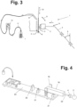
- the test device is in a further preferred embodiment, as in Fig. 2 or Fig.4 shown, equipped with at least one lifting device 21, which can be controlled by the control and monitoring unit 17, for the cylinder 16 which is rotatably mounted at the fastening points 19.
- the cylinder 16 is slightly raised in the front area before the test object 2 hits the object 3 to be tested and is lowered again immediately before the test object 2 hits the object 3 to be tested, thereby achieving a very realistic, lifelike stroking movement when pressing on the object to be tested.
- a test device which causes such a moving pressing movement on the object 3 to be tested, whereby in this schematically shown embodiment the cylinder is not operated by means of a controllable lifting device is raised.
- a mechanical design is used to generate the aforementioned downward-directed stroke-pressing movement and the movement is achieved by means of a link rod 4 arranged at an angle 8 and a cantilever provided with a spring 14, to which the test object 2 is attached.
- test device by means of which a fluid 7 can be added during the contact, stroking or attacking process of the test active object 2 on the object 3 to be tested in order to simulate various external influences.
- An application device which is automated for this purpose and operates continuously during the inspection and/or test process is described in Fig.3 shown. This is done, for example, according to Fig.3 A web-like material 6 is arranged on the test device between the object 3 to be tested and the test object 2, which automatically and dosedly releases a fluid 7 to the web-like material 6 via a conveyor device 13 by means of a positionable outlet device 12.
- the cylinder 16 can be swiveled completely, which also allows objects to be tested outside the common base plate 23.
- a further lifting device 21 on the right-hand side of the fastening device 19 for the cylinder which is controlled by the control and/or monitoring unit. This makes it very easy to check and/or test objects that cannot be placed in the holding device 15 of the testing device.
Landscapes
- Physics & Mathematics (AREA)
- Health & Medical Sciences (AREA)
- Life Sciences & Earth Sciences (AREA)
- Chemical & Material Sciences (AREA)
- Analytical Chemistry (AREA)
- Biochemistry (AREA)
- General Health & Medical Sciences (AREA)
- General Physics & Mathematics (AREA)
- Immunology (AREA)
- Pathology (AREA)
- Investigating Strength Of Materials By Application Of Mechanical Stress (AREA)
Claims (12)
- Dispositif de test (1), en particulier pour tester et/ou déterminer la résistance de surfaces ou d'objets à l'abrasion ou la sensibilité aux chocs ou la résistance aux rayures, constitué d'un dispositif de retenue (15) adaptatif ou d'un dispositif d'accès sur l'objet à tester (3) ou une surface à tester, au minimum d'un moyen pour disposer un objet actif de test (2) devant ou au-dessus de l'objet à tester, un dispositif pour déplacer (16) l'objet actif de test qui vient toucher l'objet à tester, ainsi que d'un dispositif de commande et de contrôle (17) pour la commande et le contrôle de la vitesse et de la force avec laquelle l'objet actif de test (2) entre en contact avec l'objet à tester (3),
caractérisé en ce
que le dispositif de test (1) pour le déplacement de l'objet actif de test (2) sur l'objet à tester (3) est réalisé avec un dispositif de support (4) pour l'objet actif de test, qui peut être chargé d'un poids supplémentaire (18) et qui est équipé d'un vérin de puissance actionné par un fluide ou d'un vérin pneumatique (16) avec une barre de poussée et de traction (22) non circulaire, réalisée de façon à résister à la torsion, qui est commandée par le dispositif de commande et de contrôle (17) ou peut être connectée à un tel dispositif et est montée à son extrémité dans une fixation de manière à pouvoir tourner ou tout au moins être inclinée. - Dispositif de test selon la revendication 1,
caractérisé en ce
que la barre de poussée et de traction (22) part du vérin de puissance ou du vérin pneumatique (16) et est équipée à son extrémité du dispositif de support (4). - Dispositif de test selon la revendication 1,
caractérisé en ce
que le déplacement de l'objet actif de test (2) sur l'objet à tester (3) s'effectue à la perpendiculaire ou l'horizontale de la gravité. - Dispositif de test selon la revendication 1,
caractérisé en ce
que l'objet actif de test est réalisé en tant que poinçon de test (2) avec une tête interchangeable au moins en partie élastique et qu'un matériau en bande est disposé entre ce poinçon de test et une surface à examiner et/ou un objet durant le test. - Dispositif de test selon la revendication 4,
caractérisé en ce
que le matériau en bande est réalisé au moins en partie dans un matériau textile et/ou présente une grandeur définie de rugosité. - Dispositif de test selon la revendication 1,
caractérisé en ce
que le vérin est équipé d'au moins un dispositif de chauffage. - Dispositif de test selon la revendication 1,
caractérisé en ce
que le dispositif de test est équipé d'unités séparables l'une de l'autre dans l'espace, du dispositif de déplacement pour l'objet actif de test et du dispositif de commande et/ou de contrôle. - Dispositif de test selon les revendications 1, 4 et 5,
caractérisé en ce
qu'au moins l'unité constituée d'un dispositif de retenue pour l'objet à tester, du moyen de fixation d'un matériau au moins en partie textile ainsi que du matériau lui-même et du dispositif servant au déplacement du poinçon de test contre le matériau à tester peut être logé dans une chambre climatique standard. - Dispositif de test selon une ou plusieurs des revendications précédentes,
caractérisé en ce
que la tête de l'objet actif de test déplacée contre le matériau à tester possède une dureté Shore dans la plage de 40 à 50 à une température de -40 °C. - Dispositif de test selon une ou plusieurs des revendications précédentes,
caractérisé en ce
que le vérin actionné par air comprimé, réalisé pour le déplacement de l'objet actif de test, est connecté à un boîtier ou à un dispositif de retenue au moyen d'un dispositif d'isolation ou est monté sur un tel boîtier ou dispositif de retenue. - Dispositif de test selon une ou plusieurs des revendications précédentes,
caractérisé en ce
que les lignes de connexion et/ou les connexions entre le dispositif de déplacement pour l'objet actif de test et le dispositif de commande et/ou de contrôle sont réalisées en partie chauffées et/ou de façon isolées. - Dispositif de test selon la revendication 1,
caractérisé en ce
que la tête de l'objet actif de test est équipée et/ou recouverte d'un matériau au moins en partie textile.
Applications Claiming Priority (3)
| Application Number | Priority Date | Filing Date | Title |
|---|---|---|---|
| DE102014016482.9A DE102014016482A1 (de) | 2014-11-07 | 2014-11-07 | Test- und/oder Prüfvorrichtung |
| EP15828732.6A EP3237878A1 (fr) | 2014-11-07 | 2015-11-03 | Dispositif de test et/ou d'essai |
| PCT/DE2015/000528 WO2016070864A1 (fr) | 2014-11-07 | 2015-11-03 | Dispositif de test et/ou d'essai |
Related Parent Applications (1)
| Application Number | Title | Priority Date | Filing Date |
|---|---|---|---|
| EP15828732.6A Division EP3237878A1 (fr) | 2014-11-07 | 2015-11-03 | Dispositif de test et/ou d'essai |
Publications (4)
| Publication Number | Publication Date |
|---|---|
| EP4043859A1 EP4043859A1 (fr) | 2022-08-17 |
| EP4043859C0 EP4043859C0 (fr) | 2024-09-25 |
| EP4043859B1 true EP4043859B1 (fr) | 2024-09-25 |
| EP4043859B8 EP4043859B8 (fr) | 2024-11-06 |
Family
ID=55237461
Family Applications (2)
| Application Number | Title | Priority Date | Filing Date |
|---|---|---|---|
| EP15828732.6A Withdrawn EP3237878A1 (fr) | 2014-11-07 | 2015-11-03 | Dispositif de test et/ou d'essai |
| EP22158670.4A Active EP4043859B8 (fr) | 2014-11-07 | 2015-11-03 | Dispositif de test et/ou d'essai |
Family Applications Before (1)
| Application Number | Title | Priority Date | Filing Date |
|---|---|---|---|
| EP15828732.6A Withdrawn EP3237878A1 (fr) | 2014-11-07 | 2015-11-03 | Dispositif de test et/ou d'essai |
Country Status (5)
| Country | Link |
|---|---|
| US (1) | US20190003946A1 (fr) |
| EP (2) | EP3237878A1 (fr) |
| CN (1) | CN107430051A (fr) |
| DE (1) | DE102014016482A1 (fr) |
| WO (1) | WO2016070864A1 (fr) |
Families Citing this family (8)
| Publication number | Priority date | Publication date | Assignee | Title |
|---|---|---|---|---|
| CN109975148B (zh) * | 2019-01-15 | 2024-01-26 | 中信戴卡股份有限公司 | 一种自动沙粒磨损装置 |
| DE102019133119B4 (de) | 2019-12-05 | 2025-04-03 | Universität Rostock | Vorrichtung und Verfahren zur Simulation mechanischer Belastungen an Schutzhandschuhen und/oder eines flexiblen Materials |
| CN110954431B (zh) * | 2019-12-31 | 2023-07-21 | 赛立特(南通)安全用品有限公司 | 一种防护手套手指接触面耐磨性能测试方法及装置 |
| US11262278B2 (en) * | 2020-02-18 | 2022-03-01 | Honda Motor Co., Ltd. | System and method for an inner door handle test fixture |
| DE102021103160B4 (de) * | 2021-02-10 | 2022-12-22 | Innowep Gmbh | Prüfvorrichtung und Verfahren zur Prüfung einer Oberfläche eines Prüflings |
| CN113075070B (zh) * | 2021-02-25 | 2022-12-30 | 深圳瑞生工程研究院有限公司 | 一种具有防磨损机构的墙面硬度检测装置 |
| WO2024097520A1 (fr) * | 2022-11-01 | 2024-05-10 | Dow Global Technologies Llc | Dispositif de test de raclage pour caractériser des formulations d'échantillon |
| CN117517114B (zh) * | 2024-01-04 | 2024-03-19 | 江苏欣战江纤维科技股份有限公司 | 一种用于纺织纱线的耐磨性检测设备及方法 |
Family Cites Families (18)
| Publication number | Priority date | Publication date | Assignee | Title |
|---|---|---|---|---|
| US3102414A (en) * | 1960-08-03 | 1963-09-03 | Dow Chemical Co | Carpet wear tester |
| US3974678A (en) * | 1975-03-05 | 1976-08-17 | Conchemco, Incorporated | Automatic paint cure tester |
| KR920006048B1 (ko) * | 1988-11-25 | 1992-07-27 | 주식회사 금성사 | 가열조건에서 마모분의 입도 분석이 가능한 내마모시험기 |
| GB9218827D0 (en) * | 1992-09-05 | 1992-10-21 | Primelia Consulting Services L | Friction testing apparatus |
| DE29514273U1 (de) * | 1995-09-06 | 1996-02-29 | Schneider, Gottfried, Prof. Dr.-Ing. habil., 99087 Erfurt | Tribotester CTE 396 für elastomere Werkstoffe |
| US5689058A (en) * | 1996-12-20 | 1997-11-18 | Cooper Industries, Inc. | Friction material evaluation apparatus |
| US6412330B1 (en) * | 1998-11-25 | 2002-07-02 | The Goodyear Tire & Rubber Company | Abrasion tester |
| US6401058B1 (en) * | 1999-02-12 | 2002-06-04 | Wayne State University | Reciprocating system for simulating friction and wear |
| DE10249725A1 (de) | 2002-10-25 | 2004-05-06 | Bayer Ag | Vorrichtung zur Prüfung der Kratzfestigkeit von Oberflächen |
| CN2575653Y (zh) * | 2002-10-31 | 2003-09-24 | 宝山钢铁股份有限公司 | 金属板材抗凹性试验的法向加载机构 |
| US7275423B2 (en) * | 2005-02-10 | 2007-10-02 | Toyota Technical Center Usa, Inc. | Automatic speed calculation for scratch machine |
| DE102006012374B4 (de) | 2006-03-17 | 2013-03-14 | Bayerische Motoren Werke Aktiengesellschaft | Kratzvorrichtung |
| US7997118B2 (en) * | 2007-09-26 | 2011-08-16 | Dow Global Technologies Llc | Scrub testing devices and methods |
| CN101988881B (zh) * | 2009-08-03 | 2014-04-23 | 鸿富锦精密工业(深圳)有限公司 | 漆膜硬度检测装置 |
| KR101157640B1 (ko) * | 2010-03-31 | 2012-06-18 | 한국염색기술연구소 | 충격 마찰 강도 시험기 |
| CN202033260U (zh) * | 2011-01-28 | 2011-11-09 | 浙江汇锦梯尔镀层科技有限公司 | 一种线性加载的划痕仪 |
| DE102012206886A1 (de) * | 2012-04-26 | 2013-01-10 | Bayerische Motoren Werke Aktiengesellschaft | Prüfelement zum Überprüfen einer Oberfläche |
| EP2679979B1 (fr) | 2012-06-25 | 2019-11-06 | Saint-Gobain Glass France | Testeur de rayures pour vitres |
-
2014
- 2014-11-07 DE DE102014016482.9A patent/DE102014016482A1/de active Pending
-
2015
- 2015-11-03 EP EP15828732.6A patent/EP3237878A1/fr not_active Withdrawn
- 2015-11-03 WO PCT/DE2015/000528 patent/WO2016070864A1/fr not_active Ceased
- 2015-11-03 CN CN201580067817.3A patent/CN107430051A/zh active Pending
- 2015-11-03 US US15/529,049 patent/US20190003946A1/en not_active Abandoned
- 2015-11-03 EP EP22158670.4A patent/EP4043859B8/fr active Active
Also Published As
| Publication number | Publication date |
|---|---|
| US20190003946A1 (en) | 2019-01-03 |
| DE102014016482A1 (de) | 2016-05-12 |
| CN107430051A (zh) | 2017-12-01 |
| WO2016070864A1 (fr) | 2016-05-12 |
| EP4043859C0 (fr) | 2024-09-25 |
| EP3237878A1 (fr) | 2017-11-01 |
| EP4043859A1 (fr) | 2022-08-17 |
| EP4043859B8 (fr) | 2024-11-06 |
Similar Documents
| Publication | Publication Date | Title |
|---|---|---|
| EP4043859B1 (fr) | Dispositif de test et/ou d'essai | |
| DE69917780T2 (de) | Testgerät und -verfahren zur messung der kratzfestigkeit eines films oder einer beschichtung | |
| DE102016104400B4 (de) | Prüfvorrichtung und zugehöriges betriebsverfahren | |
| DE112015004215B4 (de) | Vorrichtung und Verfahren zur Abnutzungsprüfung | |
| DE69618708T2 (de) | Mischgerät | |
| DE102011011912B4 (de) | Laborgerät mit Deckel und Pressanordnung und Verfahren zum Anpressen | |
| DE2228415A1 (de) | Ritzharteprufer | |
| DE102010034118A1 (de) | Vorrichtung zur Prüfung der Oberflächenqualität von flächigen Prüflingen | |
| DE102009012261B4 (de) | Vorrichtung zur Durchführung und Bewertung von Reißproben verschiedener Werkstoffe und Materialien | |
| DE102008028403A1 (de) | Ansatzwegaufnehmer zur Messung der Längenänderung einer Probe und diesen verwendendes Messverfahren | |
| DE10260216B3 (de) | Vorrichtung zur reproduzierbaren Prüfung der Dehnbarkeit von elastischen, bandförmigen textilen Materialien | |
| DE102014003765A1 (de) | Vorrichtung zur Messung von Triboakustik | |
| EP1061354B1 (fr) | Méthode et dispositif pour la détermination des qualités tactiles de matériaux souples | |
| DE19547100B4 (de) | Prüfgerät für die Qualität von Kunststoff-Festkörpern | |
| DE102006012374A1 (de) | Kratzvorrichtung | |
| DE10336791B4 (de) | Füllstandsensor, Messverfahren zur Ermittlung eines Anpressdrucks eines Kontaktes gegen eine Kontaktbahn eines Potentiometers und Vorrichtung zur Durchführung des Messverfahrens | |
| DE102012004846B4 (de) | Verfahren zum Beurteilen der Qualität von Reibpaarungen | |
| DE3545114C2 (fr) | ||
| EP2863172A1 (fr) | Dispositif et procédé destinés à la mesure non destructrice de l'épaisseur de couche d'une mousse en matière synthétique dans un matériau comprenant couche de mousse en matière synthétique disposée sur une couche de peau est accessible au moins sur une section depuis au moins un côté | |
| DE19953469A1 (de) | Anordnung zur Messung der tangentialen Haftkraft zwischen Probekörperflächen | |
| DE202009009946U1 (de) | Prüfstand zur tribologischen Evaluierung neuer Gleitpaarungsmaterialien für Knieendoprothesen | |
| DE102014226312A1 (de) | Prüfvorrichtung | |
| DE19715392A1 (de) | Prüfstand zur Untersuchung des Verschleißes zwischen relativ zueinander oszillierenden Prüfkörpern, insbesondere für rotatorische Oszillations-Amplituden im Mikrometerbereich | |
| DE20012911U1 (de) | Vorrichtung zur Bestimmung der Kontaktfestigkeit unter Rollenbelastung | |
| DE102009004977B4 (de) | Reibungsprüfstand |
Legal Events
| Date | Code | Title | Description |
|---|---|---|---|
| PUAI | Public reference made under article 153(3) epc to a published international application that has entered the european phase |
Free format text: ORIGINAL CODE: 0009012 |
|
| STAA | Information on the status of an ep patent application or granted ep patent |
Free format text: STATUS: THE APPLICATION HAS BEEN PUBLISHED |
|
| AC | Divisional application: reference to earlier application |
Ref document number: 3237878 Country of ref document: EP Kind code of ref document: P |
|
| AK | Designated contracting states |
Kind code of ref document: A1 Designated state(s): AL AT BE BG CH CY CZ DE DK EE ES FI FR GB GR HR HU IE IS IT LI LT LU LV MC MK MT NL NO PL PT RO RS SE SI SK SM TR |
|
| STAA | Information on the status of an ep patent application or granted ep patent |
Free format text: STATUS: REQUEST FOR EXAMINATION WAS MADE |
|
| 17P | Request for examination filed |
Effective date: 20230215 |
|
| RBV | Designated contracting states (corrected) |
Designated state(s): AL AT BE BG CH CY CZ DE DK EE ES FI FR GB GR HR HU IE IS IT LI LT LU LV MC MK MT NL NO PL PT RO RS SE SI SK SM TR |
|
| STAA | Information on the status of an ep patent application or granted ep patent |
Free format text: STATUS: EXAMINATION IS IN PROGRESS |
|
| 17Q | First examination report despatched |
Effective date: 20240129 |
|
| GRAP | Despatch of communication of intention to grant a patent |
Free format text: ORIGINAL CODE: EPIDOSNIGR1 |
|
| STAA | Information on the status of an ep patent application or granted ep patent |
Free format text: STATUS: GRANT OF PATENT IS INTENDED |
|
| INTG | Intention to grant announced |
Effective date: 20240415 |
|
| GRAS | Grant fee paid |
Free format text: ORIGINAL CODE: EPIDOSNIGR3 |
|
| GRAA | (expected) grant |
Free format text: ORIGINAL CODE: 0009210 |
|
| STAA | Information on the status of an ep patent application or granted ep patent |
Free format text: STATUS: THE PATENT HAS BEEN GRANTED |
|
| AC | Divisional application: reference to earlier application |
Ref document number: 3237878 Country of ref document: EP Kind code of ref document: P |
|
| AK | Designated contracting states |
Kind code of ref document: B1 Designated state(s): AL AT BE BG CH CY CZ DE DK EE ES FI FR GB GR HR HU IE IS IT LI LT LU LV MC MK MT NL NO PL PT RO RS SE SI SK SM TR |
|
| REG | Reference to a national code |
Ref country code: GB Ref legal event code: FG4D Free format text: NOT ENGLISH |
|
| REG | Reference to a national code |
Ref country code: CH Ref legal event code: EP |
|
| REG | Reference to a national code |
Ref country code: DE Ref legal event code: R081 Ref document number: 502015016955 Country of ref document: DE Owner name: WEINHOLD, WOLFGANG P., DE Free format text: FORMER OWNER: WEINHOLD, WOLFGANG P., DR.-ING., 97070 WUERZBURG, DE Ref country code: DE Ref legal event code: R096 Ref document number: 502015016955 Country of ref document: DE |
|
| REG | Reference to a national code |
Ref country code: CH Ref legal event code: PK Free format text: BERICHTIGUNG B8 Ref country code: CH Ref legal event code: PK Free format text: BERICHTIGUNGEN |
|
| REG | Reference to a national code |
Ref country code: IE Ref legal event code: FG4D Free format text: LANGUAGE OF EP DOCUMENT: GERMAN |
|
| RAP4 | Party data changed (patent owner data changed or rights of a patent transferred) |
Owner name: WEINHOLD, WOLFGANG P. |
|
| RIN2 | Information on inventor provided after grant (corrected) |
Inventor name: WEINHOLD, WOLFGANG P. |
|
| U01 | Request for unitary effect filed |
Effective date: 20241023 |
|
| U07 | Unitary effect registered |
Designated state(s): AT BE BG DE DK EE FI FR IT LT LU LV MT NL PT RO SE SI Effective date: 20241105 |
|
| U20 | Renewal fee for the european patent with unitary effect paid |
Year of fee payment: 10 Effective date: 20241122 |
|
| PG25 | Lapsed in a contracting state [announced via postgrant information from national office to epo] |
Ref country code: NO Free format text: LAPSE BECAUSE OF FAILURE TO SUBMIT A TRANSLATION OF THE DESCRIPTION OR TO PAY THE FEE WITHIN THE PRESCRIBED TIME-LIMIT Effective date: 20241225 |
|
| PG25 | Lapsed in a contracting state [announced via postgrant information from national office to epo] |
Ref country code: GR Free format text: LAPSE BECAUSE OF FAILURE TO SUBMIT A TRANSLATION OF THE DESCRIPTION OR TO PAY THE FEE WITHIN THE PRESCRIBED TIME-LIMIT Effective date: 20241226 |
|
| PG25 | Lapsed in a contracting state [announced via postgrant information from national office to epo] |
Ref country code: RS Free format text: LAPSE BECAUSE OF FAILURE TO SUBMIT A TRANSLATION OF THE DESCRIPTION OR TO PAY THE FEE WITHIN THE PRESCRIBED TIME-LIMIT Effective date: 20241225 |
|
| PG25 | Lapsed in a contracting state [announced via postgrant information from national office to epo] |
Ref country code: RS Free format text: LAPSE BECAUSE OF FAILURE TO SUBMIT A TRANSLATION OF THE DESCRIPTION OR TO PAY THE FEE WITHIN THE PRESCRIBED TIME-LIMIT Effective date: 20241225 Ref country code: NO Free format text: LAPSE BECAUSE OF FAILURE TO SUBMIT A TRANSLATION OF THE DESCRIPTION OR TO PAY THE FEE WITHIN THE PRESCRIBED TIME-LIMIT Effective date: 20241225 Ref country code: GR Free format text: LAPSE BECAUSE OF FAILURE TO SUBMIT A TRANSLATION OF THE DESCRIPTION OR TO PAY THE FEE WITHIN THE PRESCRIBED TIME-LIMIT Effective date: 20241226 |
|
| PG25 | Lapsed in a contracting state [announced via postgrant information from national office to epo] |
Ref country code: IS Free format text: LAPSE BECAUSE OF FAILURE TO SUBMIT A TRANSLATION OF THE DESCRIPTION OR TO PAY THE FEE WITHIN THE PRESCRIBED TIME-LIMIT Effective date: 20250125 |
|
| PG25 | Lapsed in a contracting state [announced via postgrant information from national office to epo] |
Ref country code: SM Free format text: LAPSE BECAUSE OF FAILURE TO SUBMIT A TRANSLATION OF THE DESCRIPTION OR TO PAY THE FEE WITHIN THE PRESCRIBED TIME-LIMIT Effective date: 20240925 |
|
| PG25 | Lapsed in a contracting state [announced via postgrant information from national office to epo] |
Ref country code: ES Free format text: LAPSE BECAUSE OF FAILURE TO SUBMIT A TRANSLATION OF THE DESCRIPTION OR TO PAY THE FEE WITHIN THE PRESCRIBED TIME-LIMIT Effective date: 20240925 |
|
| PG25 | Lapsed in a contracting state [announced via postgrant information from national office to epo] |
Ref country code: PL Free format text: LAPSE BECAUSE OF FAILURE TO SUBMIT A TRANSLATION OF THE DESCRIPTION OR TO PAY THE FEE WITHIN THE PRESCRIBED TIME-LIMIT Effective date: 20240925 Ref country code: CZ Free format text: LAPSE BECAUSE OF FAILURE TO SUBMIT A TRANSLATION OF THE DESCRIPTION OR TO PAY THE FEE WITHIN THE PRESCRIBED TIME-LIMIT Effective date: 20240925 |
|
| PG25 | Lapsed in a contracting state [announced via postgrant information from national office to epo] |
Ref country code: SK Free format text: LAPSE BECAUSE OF FAILURE TO SUBMIT A TRANSLATION OF THE DESCRIPTION OR TO PAY THE FEE WITHIN THE PRESCRIBED TIME-LIMIT Effective date: 20240925 |
|
| PG25 | Lapsed in a contracting state [announced via postgrant information from national office to epo] |
Ref country code: MC Free format text: LAPSE BECAUSE OF FAILURE TO SUBMIT A TRANSLATION OF THE DESCRIPTION OR TO PAY THE FEE WITHIN THE PRESCRIBED TIME-LIMIT Effective date: 20240925 |
|
| PLBE | No opposition filed within time limit |
Free format text: ORIGINAL CODE: 0009261 |
|
| STAA | Information on the status of an ep patent application or granted ep patent |
Free format text: STATUS: NO OPPOSITION FILED WITHIN TIME LIMIT |
|
| GBPC | Gb: european patent ceased through non-payment of renewal fee |
Effective date: 20241225 |
|
| 26N | No opposition filed |
Effective date: 20250626 |
|
| PG25 | Lapsed in a contracting state [announced via postgrant information from national office to epo] |
Ref country code: GB Free format text: LAPSE BECAUSE OF NON-PAYMENT OF DUE FEES Effective date: 20241225 |
|
| PG25 | Lapsed in a contracting state [announced via postgrant information from national office to epo] |
Ref country code: IE Free format text: LAPSE BECAUSE OF NON-PAYMENT OF DUE FEES Effective date: 20241103 |
|
| REG | Reference to a national code |
Ref country code: CH Ref legal event code: U11 Free format text: ST27 STATUS EVENT CODE: U-0-0-U10-U11 (AS PROVIDED BY THE NATIONAL OFFICE) Effective date: 20251218 |
|
| U20 | Renewal fee for the european patent with unitary effect paid |
Year of fee payment: 11 Effective date: 20251125 |
|
| PG25 | Lapsed in a contracting state [announced via postgrant information from national office to epo] |
Ref country code: HR Free format text: LAPSE BECAUSE OF FAILURE TO SUBMIT A TRANSLATION OF THE DESCRIPTION OR TO PAY THE FEE WITHIN THE PRESCRIBED TIME-LIMIT Effective date: 20240925 |
|
| PGFP | Annual fee paid to national office [announced via postgrant information from national office to epo] |
Ref country code: CH Payment date: 20251218 Year of fee payment: 11 |
|
| PG25 | Lapsed in a contracting state [announced via postgrant information from national office to epo] |
Ref country code: HU Free format text: LAPSE BECAUSE OF FAILURE TO SUBMIT A TRANSLATION OF THE DESCRIPTION OR TO PAY THE FEE WITHIN THE PRESCRIBED TIME-LIMIT; INVALID AB INITIO Effective date: 20151103 |
|
| PG25 | Lapsed in a contracting state [announced via postgrant information from national office to epo] |
Ref country code: CY Free format text: LAPSE BECAUSE OF FAILURE TO SUBMIT A TRANSLATION OF THE DESCRIPTION OR TO PAY THE FEE WITHIN THE PRESCRIBED TIME-LIMIT; INVALID AB INITIO Effective date: 20151103 |