EP4043944B1 - Capteur d'angle de faisceau dans un système de réalité virtuelle/augmentée - Google Patents
Capteur d'angle de faisceau dans un système de réalité virtuelle/augmentée Download PDFInfo
- Publication number
- EP4043944B1 EP4043944B1 EP22164912.2A EP22164912A EP4043944B1 EP 4043944 B1 EP4043944 B1 EP 4043944B1 EP 22164912 A EP22164912 A EP 22164912A EP 4043944 B1 EP4043944 B1 EP 4043944B1
- Authority
- EP
- European Patent Office
- Prior art keywords
- light
- generation system
- orthogonal
- image generation
- angle
- Prior art date
- Legal status (The legal status is an assumption and is not a legal conclusion. Google has not performed a legal analysis and makes no representation as to the accuracy of the status listed.)
- Active
Links
Images









Classifications
-
- G—PHYSICS
- G02—OPTICS
- G02B—OPTICAL ELEMENTS, SYSTEMS OR APPARATUS
- G02B27/00—Optical systems or apparatus not provided for by any of the groups G02B1/00 - G02B26/00, G02B30/00
- G02B27/01—Head-up displays
- G02B27/017—Head mounted
- G02B27/0172—Head mounted characterised by optical features
-
- G—PHYSICS
- G01—MEASURING; TESTING
- G01B—MEASURING LENGTH, THICKNESS OR SIMILAR LINEAR DIMENSIONS; MEASURING ANGLES; MEASURING AREAS; MEASURING IRREGULARITIES OF SURFACES OR CONTOURS
- G01B11/00—Measuring arrangements characterised by the use of optical techniques
- G01B11/26—Measuring arrangements characterised by the use of optical techniques for measuring angles or tapers; for testing the alignment of axes
- G01B11/27—Measuring arrangements characterised by the use of optical techniques for measuring angles or tapers; for testing the alignment of axes for testing the alignment of axes
- G01B11/272—Measuring arrangements characterised by the use of optical techniques for measuring angles or tapers; for testing the alignment of axes for testing the alignment of axes using photoelectric detection means
-
- G—PHYSICS
- G02—OPTICS
- G02B—OPTICAL ELEMENTS, SYSTEMS OR APPARATUS
- G02B26/00—Optical devices or arrangements for the control of light using movable or deformable optical elements
- G02B26/08—Optical devices or arrangements for the control of light using movable or deformable optical elements for controlling the direction of light
- G02B26/10—Scanning systems
- G02B26/103—Scanning systems having movable or deformable optical fibres, light guides or waveguides as scanning elements
-
- G—PHYSICS
- G02—OPTICS
- G02B—OPTICAL ELEMENTS, SYSTEMS OR APPARATUS
- G02B27/00—Optical systems or apparatus not provided for by any of the groups G02B1/00 - G02B26/00, G02B30/00
- G02B27/0081—Optical systems or apparatus not provided for by any of the groups G02B1/00 - G02B26/00, G02B30/00 with means for altering, e.g. enlarging, the entrance or exit pupil
-
- G—PHYSICS
- G02—OPTICS
- G02B—OPTICAL ELEMENTS, SYSTEMS OR APPARATUS
- G02B27/00—Optical systems or apparatus not provided for by any of the groups G02B1/00 - G02B26/00, G02B30/00
- G02B27/0093—Optical systems or apparatus not provided for by any of the groups G02B1/00 - G02B26/00, G02B30/00 with means for monitoring data relating to the user, e.g. head-tracking, eye-tracking
-
- G—PHYSICS
- G02—OPTICS
- G02B—OPTICAL ELEMENTS, SYSTEMS OR APPARATUS
- G02B27/00—Optical systems or apparatus not provided for by any of the groups G02B1/00 - G02B26/00, G02B30/00
- G02B27/01—Head-up displays
- G02B27/0179—Display position adjusting means not related to the information to be displayed
-
- G—PHYSICS
- G02—OPTICS
- G02B—OPTICAL ELEMENTS, SYSTEMS OR APPARATUS
- G02B27/00—Optical systems or apparatus not provided for by any of the groups G02B1/00 - G02B26/00, G02B30/00
- G02B27/10—Beam splitting or combining systems
-
- G—PHYSICS
- G02—OPTICS
- G02B—OPTICAL ELEMENTS, SYSTEMS OR APPARATUS
- G02B27/00—Optical systems or apparatus not provided for by any of the groups G02B1/00 - G02B26/00, G02B30/00
- G02B27/30—Collimators
-
- G—PHYSICS
- G02—OPTICS
- G02B—OPTICAL ELEMENTS, SYSTEMS OR APPARATUS
- G02B30/00—Optical systems or apparatus for producing three-dimensional [3D] effects, e.g. stereoscopic images
-
- G—PHYSICS
- G02—OPTICS
- G02B—OPTICAL ELEMENTS, SYSTEMS OR APPARATUS
- G02B6/00—Light guides; Structural details of arrangements comprising light guides and other optical elements, e.g. couplings
- G02B6/0001—Light guides; Structural details of arrangements comprising light guides and other optical elements, e.g. couplings specially adapted for lighting devices or systems
- G02B6/0011—Light guides; Structural details of arrangements comprising light guides and other optical elements, e.g. couplings specially adapted for lighting devices or systems the light guides being planar or of plate-like form
- G02B6/0013—Means for improving the coupling-in of light from the light source into the light guide
-
- G—PHYSICS
- G02—OPTICS
- G02B—OPTICAL ELEMENTS, SYSTEMS OR APPARATUS
- G02B6/00—Light guides; Structural details of arrangements comprising light guides and other optical elements, e.g. couplings
- G02B6/0001—Light guides; Structural details of arrangements comprising light guides and other optical elements, e.g. couplings specially adapted for lighting devices or systems
- G02B6/0011—Light guides; Structural details of arrangements comprising light guides and other optical elements, e.g. couplings specially adapted for lighting devices or systems the light guides being planar or of plate-like form
- G02B6/0013—Means for improving the coupling-in of light from the light source into the light guide
- G02B6/0015—Means for improving the coupling-in of light from the light source into the light guide provided on the surface of the light guide or in the bulk of it
- G02B6/0016—Grooves, prisms, gratings, scattering particles or rough surfaces
-
- G—PHYSICS
- G06—COMPUTING OR CALCULATING; COUNTING
- G06F—ELECTRIC DIGITAL DATA PROCESSING
- G06F3/00—Input arrangements for transferring data to be processed into a form capable of being handled by the computer; Output arrangements for transferring data from processing unit to output unit, e.g. interface arrangements
- G06F3/002—Specific input/output arrangements not covered by G06F3/01 - G06F3/16
-
- G—PHYSICS
- G06—COMPUTING OR CALCULATING; COUNTING
- G06F—ELECTRIC DIGITAL DATA PROCESSING
- G06F3/00—Input arrangements for transferring data to be processed into a form capable of being handled by the computer; Output arrangements for transferring data from processing unit to output unit, e.g. interface arrangements
- G06F3/01—Input arrangements or combined input and output arrangements for interaction between user and computer
- G06F3/011—Arrangements for interaction with the human body, e.g. for user immersion in virtual reality
-
- G—PHYSICS
- G06—COMPUTING OR CALCULATING; COUNTING
- G06F—ELECTRIC DIGITAL DATA PROCESSING
- G06F3/00—Input arrangements for transferring data to be processed into a form capable of being handled by the computer; Output arrangements for transferring data from processing unit to output unit, e.g. interface arrangements
- G06F3/01—Input arrangements or combined input and output arrangements for interaction between user and computer
- G06F3/011—Arrangements for interaction with the human body, e.g. for user immersion in virtual reality
- G06F3/012—Head tracking input arrangements
-
- G—PHYSICS
- G06—COMPUTING OR CALCULATING; COUNTING
- G06T—IMAGE DATA PROCESSING OR GENERATION, IN GENERAL
- G06T15/00—Three-dimensional [3D] image rendering
- G06T15/50—Lighting effects
-
- G—PHYSICS
- G06—COMPUTING OR CALCULATING; COUNTING
- G06T—IMAGE DATA PROCESSING OR GENERATION, IN GENERAL
- G06T19/00—Manipulating three-dimensional [3D] models or images for computer graphics
- G06T19/006—Mixed reality
-
- G—PHYSICS
- G02—OPTICS
- G02B—OPTICAL ELEMENTS, SYSTEMS OR APPARATUS
- G02B27/00—Optical systems or apparatus not provided for by any of the groups G02B1/00 - G02B26/00, G02B30/00
- G02B27/01—Head-up displays
- G02B27/0101—Head-up displays characterised by optical features
- G02B2027/011—Head-up displays characterised by optical features comprising device for correcting geometrical aberrations, distortion
-
- G—PHYSICS
- G02—OPTICS
- G02B—OPTICAL ELEMENTS, SYSTEMS OR APPARATUS
- G02B27/00—Optical systems or apparatus not provided for by any of the groups G02B1/00 - G02B26/00, G02B30/00
- G02B27/01—Head-up displays
- G02B27/0101—Head-up displays characterised by optical features
- G02B2027/0123—Head-up displays characterised by optical features comprising devices increasing the field of view
- G02B2027/0125—Field-of-view increase by wavefront division
-
- G—PHYSICS
- G02—OPTICS
- G02B—OPTICAL ELEMENTS, SYSTEMS OR APPARATUS
- G02B27/00—Optical systems or apparatus not provided for by any of the groups G02B1/00 - G02B26/00, G02B30/00
- G02B27/01—Head-up displays
- G02B27/017—Head mounted
- G02B2027/0178—Eyeglass type
-
- G—PHYSICS
- G02—OPTICS
- G02B—OPTICAL ELEMENTS, SYSTEMS OR APPARATUS
- G02B6/00—Light guides; Structural details of arrangements comprising light guides and other optical elements, e.g. couplings
- G02B6/24—Coupling light guides
- G02B6/26—Optical coupling means
- G02B6/34—Optical coupling means utilising prism or grating
Definitions
- a user wearing a head-worn display views a virtual representation of a three-dimensional (3D) object on the display and walks around the area where the 3D object appears, that 3D object can be re-rendered for each viewpoint, giving the end user the perception that he or she is walking around an object that occupies real space.
- the head-worn display is used to present multiple objects within a virtual space (for instance, a rich virtual world)
- measurements of head pose can be used to re-render the scene to match the end user's dynamically changing head location and orientation and provide an increased sense of immersion in the virtual space.
- the display subsystem includes one or more planar optical waveguides that are generally parallel to the field of view of the user, and into which light from the optical fiber(s) is injected.
- One or more linear diffraction gratings are embedded within the waveguide(s) to change the angle of incident light propagating along the waveguide(s). By changing the angle of light beyond the threshold of total internal reflection (TIR), the light escapes from one or more lateral faces of the waveguide(s).
- TIR total internal reflection
- the linear diffraction grating(s) have a low diffraction efficiency, so only a fraction of the light energy is directed out of the waveguide(s), each time the light encounters the linear diffraction grating(s).
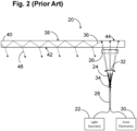
- a display subsystem 20 comprises one or more light sources 22 that generates light, an optical fiber 24 that emits the light, and a collimation element 26 that collimates the light exiting the distal end of the optical fiber 24 into a light beam 36.
- the display subsystem 20 further comprises a piezoelectric element 28 to or in which the optical fiber 24 is mounted as a fixed-free flexible cantilever, and drive electronics 30 electrically coupled to the piezoelectric element 22 to activate electrically stimulate the piezoelectric element 28, thereby causing the distal end of the optical fiber 24 to vibrate in a pre-determined scan pattern that creates deflections 32 about a fulcrum 34, thereby scanning the collimated light beam 36 in accordance with the scan pattern.
- the actual angles of the exiting light rays 48 will vary from the designed angles of the exiting light rays 48, thereby creating pixels that are in the incorrect locations within the field of view of the end user, resulting in image distortion.
- the display subsystem further comprises an in-coupling element (ICE) configured for directing the light beam from the collimation element down the waveguide apparatus, such that light rays exit the waveguide apparatus to display a pixel of an image frame to the end user.
- the pixel has a location encoded with angles of the exiting light rays.
- the waveguide apparatus comprises a planar optical waveguide (e.g., one formed of a single pan of optically transparent material), in which case, the ICE is configured for optically coupling the collimated light beam from the imaging element into the planar optical waveguide as an in-coupled light beam.
- the pair of orthogonal sensors may respectively comprise first and second polarization elements configured for respectively polarizing each of the representative light ray(s) into orthogonally polarized light rays.
- the angle selective layers may be strained in orthogonal orientations.
- a virtual image generation system for use by an end user.
- the virtual image generation system comprises a projection subsystem configured for generating a collimated light beam.
- the projection subsystem comprises at least one light source configured for generating light, an optical fiber configured for emitting the light, a collimation element configured for collimating the light from the optical fiber into the collimated light beam, and a mechanical drive assembly to which the optical fiber is mounted.
- the mechanical drive assembly is configured for displacing the optical fiber in accordance with a scan pattern.
- the mechanical drive assembly may comprise a piezoelectric element to which the optical fiber is mounted, and drive electronics configured for conveying electrical signals to the piezoelectric element, thereby causing the optical fiber to vibrate in accordance with the scan pattern.
- the virtual image generation system further comprises a display configured emitting light rays in response to the collimated light beam to display a pixel of an image frame to the end user.
- the pixel has a location encoded with angles of the emitted light rays.
- the display is configured for displaying the pixel of the image frame selectively at one of a plurality of different focal points to the end user.
- the display may be configured for being positioned in front of the eyes of the end user.
- the display may have a partially transparent display surface configured for being positioned in the field of view between the eyes of the end user and an ambient environment.
- the virtual image generation system further comprises a frame structure configured for being worn by the end user, the frame structure carrying the display.
- the virtual image generation system further comprises a sensing assembly configured for sensing at least one parameter indicative of the emitted light ray angle(s).
- the parameter(s) sensed by the sensing assembly is indicative of the exiting light ray angle(s) projected in at least one plane (e.g., two orthogonal planes that are orthogonal to each other) that is orthogonal to a plane coincides with the exterior surface of the waveguide apparatus.
- the virtual image generation system 100 may be operated as an augmented reality subsystem, providing images of virtual objects intermixed with physical objects in a field of view of an end user 50.
- a first approach employs one or more imagers (e.g., cameras) to capture images of the ambient environment.
- the virtual image generation system 100 inter-mixes the virtual images into the data representing the images of the ambient environment.
- a second approach employs one or more at least partially transparent surfaces through which the ambient environment can be seen and onto which the virtual image generation system 100 produces images of virtual objects.
- the virtual image generation system 100 may be employed in applications other than augmented reality and virtual reality subsystems.
- various techniques may be applied to any projection or display subsystem, or may be applied to pico projectors where movement may be made by an end user's hand rather than the head.
- the teachings should not be limited to such subsystems of such uses.
- the virtual image generation system 100 comprises a frame structure 102 worn by an end user 50, a display subsystem 104 carried by the frame structure 102, such that the display subsystem 104 is positioned in front of the eyes 52 of the end user 50, and a speaker 106 carried by the frame structure 102, such that the speaker 106 is positioned adjacent the ear canal of the end user 50 (optionally, another speaker (not shown) is positioned adjacent the other ear canal of the end user 50 to provide for stereo/shapeable sound control).
- the display subsystem 104 is designed to present the eyes 52 of the end user 50 with photo-based radiation patterns that can be comfortably perceived as augmentations to physical reality, with high-levels of image quality and three-dimensional perception, as well as being capable of presenting two-dimensional content.
- the display subsystem 104 presents a sequence of frames at high frequency that provides the perception of a single coherent scene.
- the display subsystem 104 employs "optical see-through” display through which the user can directly view light from real objects via transparent (or semi-transparent) elements.
- the transparent element often referred to as a “combiner,” superimposes light from the display over the user's view of the real world.
- the display subsystem 104 comprises a projection subsystem 108 and a partially transparent display screen 110 on which the projection subsystem 108 projects images.
- the display screen 110 is positioned in the end user's 50 field of view between the eyes 52 of the end user 50 and an ambient environment, such that direct light from the ambient environment is transmitted through the display screen 110 to the eyes 52 of the end user 50.
- the projection assembly 108 provides a scanned light to the partially transparent display screen 110, thereby combining with the direct light from the ambient environment, and being transmitted from the display screen 110 to the eyes 52 of the user 50.
- the projection subsystem 108 takes the form of an optical fiber scan-based projection device
- the display screen 110 takes the form of a waveguide-based display into which the scanned light from the projection subsystem 108 is injected to produce, e.g., images at a single optical viewing distance closer than infinity (e.g., arm's length), images at multiple, discrete optical viewing distances or focal planes, and/or image layers stacked at multiple viewing distances or focal planes to represent volumetric 3D objects.
- the control subsystem of virtual image generation system 100 comprises a central processing unit (CPU) 114, a graphics processing unit (GPU) 116, one or more frame buffers 118, and three-dimensional data base 120 for storing three-dimensional scene data.
- the CPU 114 controls overall operation, while the GPU 116 renders frames (i.e., translating a three-dimensional scene into a two-dimensional image) from the three-dimensional data stored in the three-dimensional data base 120 and stores these frames in the frame buffer(s) 116.
- one or more additional integrated circuits may control the reading into and/or reading out of frames from the frame buffer(s) 116 and operation of the projection assembly 108 of the display subsystem 104.
- the local processing and data module 130 may comprise a power-efficient processor or controller, as well as digital memory, such as flash memory, both of which may be utilized to assist in the processing, caching, and storage of data captured from the sensors and/or acquired and/or processed using the remote processing module 132 and/or remote data repository 134, possibly for passage to the display subsystem 104 after such processing or retrieval.
- the remote processing module 132 may comprise one or more relatively powerful processors or controllers configured to analyze and process data and/or image information.
- the remote data repository 134 may comprise a relatively large-scale digital data storage facility, which may be available through the internet or other networking configuration in a "cloud" resource configuration. In one embodiment, all data is stored and all computation is performed in the local processing and data module 130, allowing fully autonomous use from any remote modules.
- the optical coupling subsystem 164 further comprises an in-coupling element (ICE) 168, for instance, one or more reflective surfaces, diffraction gratings, mirrors, dichroic mirrors, or prisms to optically couple light into the end of the display screen 110.
- ICE in-coupling element
- the display screen 110 takes the form of a waveguide apparatus 170 that includes a planar optical waveguide 172 and one or more diffractive optical elements (DOEs) 174 associated with the planar optical waveguide 172.
- the waveguide apparatus 170 may comprise multiple planar optical waveguides 172 and DOEs 174 respectively associated with the planar optical waveguides 172.
- the planar optical waveguide 172 has a first end 176a and a second end 176b, the second end 176b opposed to the first end 176a along a length 178 of the planar optical waveguide 172.
- a collimated light beam 200 entering the waveguide 172 at one of two different angles will follow one of the two TIR optical paths 182a, 182b, resulting in light rays 202 exiting the planar optical waveguide 172 along one of the two sets of external optical paths. That is, a collimated light beam 200a that enters the waveguide 172 at an angle represented by the TIR optical path 182a will result in the light rays 202a exiting the planar optical waveguide 172 along the set of external optical paths, and a collimated light beam 200b that enters the waveguide 172 at an angle represented by the TIR optical path 182b will result in the light rays 202b exiting the planar optical waveguide 172 along the set of external optical paths.
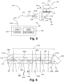
- the light ray angle sensing assembly 122 is located between the ICE 168 and the DOE(s) 174 for directly or indirectly sensing the angle of the light rays 202 exiting the waveguide apparatus 170, although the sensing assembly 122 may be located anywhere along the optical path of the collimated light beam 200. Further details discussing the sensing assembly 122 will be described in further detail below.
- the frame 250 is generated using a raster scan pattern 260.
- the raster scan pattern 260 typically presents pixels 268 from left to right (indicated by arrows 262a, 262b, then from top to bottom (indicated by arrow 264).
- the presentation may start at the upper right corner and traverse left across a first line 266a until the end of the line is reached.
- the raster scan pattern 260 typically then starts from the left in a next line down.
- the presentation may be temporarily blacked out or blanked when returning from the end of one line to the start of the next line.
- This process repeats line-by-line until the bottom line 266n is completed, for example, at the bottom right most pixel 268.
- a new frame is started, again returning to the right of the top most line of the next frame. Again, the presentation may be blanked while returning from the bottom left to the top right to present the next frame.
- interlaced raster scan patterns lines from the first and the second fields 258a, 258b are interlaced.
- the pixel information for the first field 258a may be used for the odd numbered lines only, while the pixel information for the second field 258b may be used for the even numbered lines only.
- all of the lines of the first field 258a of the frame 250 ( Fig. 7 ) are typically presented before the lines of the second field 258b.
- the first field 258a may be presented using the pixel information of the first field 258a to sequentially present line 1, line 3, line 5, etc.
- the second field 258b of the frame 250 ( Fig. 7 ) may be presented following the first field 258a, by using the pixel information of the second field 258b to sequentially present line 2, line 4, line 6, etc.
- a Lissajous scan pattern 280 may alternatively be used to generate the frame 250.
- the Lissajous scan pattern 280 may consist of a single Lissajous scan line 282, which may include one or more complete angular cycles (e.g., 360 degrees), which may be denominated as coils or loops.
- the Lissajous scan pattern 280 may include two or more Lissajous scan lines 282, each phase shifted with respect to one another to nest the Lissajous scan lines 282.
- the pixel information is used to specify the color and/or intensity of each sequential pixel, as the angle increments.
- An amplitude or radial value specifies a radial dimension 284 from a starting point 286 of the Lissajous scan line 282.
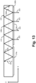
- the DOE(s) 174 are associated with the substrate 172 (e.g., incorporated within the substrate 172 or abutting or adjacent one or more of the faces 180a, 180b of the substrate 172) for two-dimensionally expanding the effective exit pupil of the collimated light beam 200 optically coupled into the substrate 172.
- the DOE(s) 174 comprises one or more orthogonal pupil expansion (OPE) elements 174a (only one shown in Fig.
- the substrate 172 is adjacent the face 180b of the substrate 172 for splitting the in-coupled light beam 200 into orthogonal light beams 201, and an exit pupil expansion (EPE) element 174b associated with the substrate 172 for splitting each orthogonal light beam 201 into the out-coupled light rays 202 that exit the face 180b of the substrate 172 towards the eye(s) 52 of the end user 50.
- the OPE element(s) 174 and EPE element 174b may be incorporated into different panes of the substrate 172.
- the OPE element 174a has a relatively low diffraction efficiency (e.g., less than 50%), and comprises a series of diagonal diffractive elements (forty-five degrees relative to the x-axis), such that, at each point of intersection with the OPE element 174a, a portion (e.g., greater than 90%) of the in-coupled light beam 200 continues to propagate within the substrate 172 via TIR along the internally reflective optical path 204a, and the remaining portion (e.g., less than 10%) of the in-coupled light beam 200 is diffracted as an orthogonal light beam 201 that propagates within the substrate 172 via TIR along an internally reflective optical path 204b (in this case, along the horizontal or x-axis) toward the EPE element 174b.
- a portion e.g., greater than 90%
- the remaining portion e.g., less than 10%
- optical paths 204b are described as being perpendicular or orthogonal to the optical path 204a, the optical paths 204b may alternatively be obliquely oriented with respect to the optical path 204a.
- the exit pupil of the collimated light beam 200 in-coupled into the waveguide apparatus 170 is expanded vertically along the y-axis by the OPE element 174a.
- the EPE element 174b further expands the light's effective exit pupil along the first axis (horizontal x-axis in Fig. 12 ).
- the EPE element 174b like the OPE element 174a, has a relatively low diffraction efficiency (e.g., less than 50%), such that, at each point of intersection with the EPE element 174b, a portion (e.g., greater than 90%) of each orthogonal light beam 201 continues to propagate along the respective internally reflective optical path 204b, and the remaining portion of each orthogonal light beam 201 is diffracted as an out-coupled light ray 202 that exits the face 180b of the substrate 172 (along the z-axis), as illustrated in Figs.
- a relatively low diffraction efficiency e.g., less than 50%
- the out-coupled light rays 202 exiting the face 180b of the substrate 172 can be rendered even more divergent from the perspective of the eye(s) 52 of the end user 50 (i.e., a more convex curvature will be imparted on the light wavefront), and require the eye(s) 52 to accommodate to an even closer distance to bring the resulting image into focus on the retina and would be interpreted by the brain of the end user 50 as light from a viewing distance (e.g., 0.5 meters) closer to the eye(s) 52, as shown in Fig. 17c .
- a viewing distance e.g., 0.5 meters
- waveguide apparatus 170 has been described herein as having only one focal plane, it should be appreciated that multiple planar optical waveguides 172 with associated OPEs 178 and EPEs 180 can be used to simultaneously or concurrently generate images at multiple focal planes, as discussed in U.S. Patent Publication Nos. 2015/0309264 and 2015/0346490 .
- the display subsystem 104 comprises a sensing assembly 122 configured for sensing at least one parameter indicative of the angle of at least one of the light rays 202 exiting the waveguide apparatus 170.
- the sensing assembly 122 senses the parameter(s) indicative of the angle of the light ray(s) 202 relative to one or more reference planes.
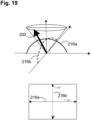
- these reference planes may comprise the x-z plane, y-z plane, and x-y plane, as described in further detail below.
- these reference planes may be flat, but because the exterior surface of the waveguide apparatus 170 may alternatively be curved to conform to the head 54 of the user 50, these reference planes may be curved as well.
- the orientation of an exiting light ray 202 from an origin in three-dimensional space may be defined by two angles, one on the x-z plane 216a and another on the y-z plane 216b, which closely correspond to the respective x- and y-coordinates of the pixel 212 in the x-y plane of the FOV 214.
- the CPU 114 may determine the actual angles of the exiting light ray 202 in the x-z and y-z planes 216a, 216b based on parameters sensed by the sensing assembly 122, compute a deviation between the actual angles of the exiting light ray 202 and the as-designed angles of the exiting light ray 202 for the corresponding pixel 212, and modifies the operation of the projection subsystem 108 to compensate for the discrepancy between the actual angles of the exiting light ray 202 and the as-designed angles of the exiting light ray 202.
- the parameters detected by the sensing assembly 122 comprises an intensity of at least one of the light rays 202 relative to the x-z and y-z planes 216a, 216b.
- the sensing assembly 122 measures the intensity of at least one light ray 203 (only one described herein) representative of the light rays 202 exiting or emitted from the waveguide apparatus 170.
- the representative light ray 203 is different from the exiting light rays 202, and will exit the waveguide apparatus 170 at a different location from the exiting light rays 202, preferably outside of the FOV 214 of the end user 50.
- the waveguide apparatus 170 further comprises an additional DOE 190 for out-coupling light from the waveguide apparatus 170 as the representative light ray 203 to the sensing assembly 122, as illustrated in Figs. 12-14 .
- each dielectric layer 226 transmit light energy as a known function of the angle at which the light energy is incident on the plane of the dielectric layer 226 (which is located in the x-y plane). For example, as can be seen from an exemplary dielectric layer transmission-angle relationship illustrated in Fig. 21a , the closer the angle of the representative light ray 203 is to the normal of the plane of the dielectric layer 226 (0 degrees), the greater the energy of the representative light ray 203 is transmitted to the photo-intensity sensor 224. Furthermore, each photo-intensity sensor 224 will generate a voltage that is a known function of the intensity of light energy incident at an angle normal to the plane of the respective dielectric layer 226.
- the photo-intensity sensors 224 themselves will have some degree of angular dependency, which can be utilized as a primary means of sensing the angle of the representative light ray 203, in which case, the angle sensors 220 may not include dielectric layers 226, or can be utilized as a secondary or auxiliary means of sensing the angle of the representative light ray 203 in addition to the use of the dielectric layers 226 in the angle sensors 220.
- a photodetector intensity-angle relationship (not shown), which correlates the voltage sensed by the respective photo-intensity sensor 224 to a range of light incident angles, may be generated.
- This photodetector intensity-angle relationship by itself, can be used to determine the angle of the representative light ray 203, or may be used to confirm the angle of the representative light ray 203 determined from the dielectric layer transmission-angle relationship ( Fig. 21a ) and the photodetector intensity-voltage relationship ( Fig. 21b ).
- the sensing assembly 122 breaks the circular symmetry of the dielectric layers 226, thereby allowing the orientation of the representative light ray 203 to be projected into the x-z and y-z planes 216a, 216b.
- the cylindrical lenses 228a, 228b are configured for respectively passing the first and second orthogonal components of the representative light ray 203 (corresponding to the x-z and y-z planes 216a, 216b) to the respective dielectric layers 226a, 226b.
- each angle sensor 220 is described as detecting one representative light ray 203 for purposes of brevity and clarity in illustration, each of the angle sensors 220, in reality, detects many light rays, and therefore, the voltage outputs of angle sensors 220 will be representative of the composite of the horizontal component 203a or vertical component 203b of the representative light ray 203.
- the DOE 190 preferably has a linear diffraction pattern, such that the angles of the representative light ray 203 exiting the DOE 190 are uniform given a specific angle of the in-coupled collimated beam 200.
- the DOE 190 may be segmented into a portion that passes one orthogonal component to the angle sensor 220a and another portion that passes the other orthogonal component to the angle sensor 220b in the same manner that as the cylindrical lenses 228 described above.
- the DOE 190 itself, may be segmented into a portion that passes one orthogonal component to the angle sensor 220a and another portion that passes the other orthogonal component to the angle sensor 220b in the same manner that as the cylindrical lenses 228 described above.
- the angle sensors 220 respectively comprise a pair of polarization elements 230a, 230b (collectively, 230) configured for polarizing the representative light ray 203 into orthogonally polarized light rays, which are then passed to the respective photo-intensity sensors 224a, 224b via the dielectric layers 226a, 226b.
- the dielectric layers 226a, 226b themselves, can be strained in orthogonal orientations, such that the dielectric layers 226 are no longer isotropic, but rather are anisotropic, and tend to pass the representative light ray 203 in one orthogonal direction more than in the other orthogonal direction, and vice versa.
- the angle sensors 220 may alternatively be closely associated with the EPE element 174b.
- the light rays 202 exiting the waveguide apparatus 170 will comprise the representative light ray sensed by the angle sensors 220.
- the light rays 202 sensed by the angle sensors 220 may be divergent, and thus somewhat non-uniform, given any particular angle of the in-coupled collimated beam 200, since the EPE element 174b may have a radially symmetric diffraction pattern that creates a focal plane that is not at optical-infinity.
- the size of the angle sensors 220 will preferably be relatively small, and as such, the angle variance between the light rays impinging on an angle sensor 220 will be insignificant.
- the angle sensors 220 are only capable of sensing information from which an absolute angle of the exiting light rays 202 in the x-z plane 216a or y-z plane 216b can be obtained (e.g., an absolute angle of 30° may be +30° or -30°).
- the sensing assembly 122 senses another parameter indicative of the relative angle of the exiting light rays 202 in the x-z plane 216a or y-z plane 216b.
- this sensed parameter comprises a quadrant in which the collimated light beam 200 is projected in a plane, so that the sign of the angles of the light rays 202 projected onto the x-z and y-z planes 216a, 216b can be determined.
- one exiting light ray 202 forms an angle relative to the x-y plane 216c. That is, when projected onto the x-y plane 216c, the exiting light ray 202 may form an angle in the x-y plane 216c, as illustrated in Fig. 22b .
- the angle of the exiting light ray 202 projected within second quadrant of the x-y plane 216c and therefore, it can be determined that the angle that the exiting light ray 202 makes in the x-z plane 216a has a negative sign, and the angle that the exiting light ray 202 makes in the y-z plane 216b should have a positive sign.
- the sensing assembly 122 may comprise a quadrant position sensing detector (PSD) 236 centered at the intersection of the quadrants.
- PSD quadrant position sensing detector
- the quadrant in which the light rays 202 are projected into the x-y plane 216c can simply be inferred from the quadrant of the current scan position in the scan pattern when the intensity of the exiting light rays 202 is sensed by the sensing assembly 122.
Landscapes
- Physics & Mathematics (AREA)
- General Physics & Mathematics (AREA)
- Engineering & Computer Science (AREA)
- Optics & Photonics (AREA)
- Theoretical Computer Science (AREA)
- General Engineering & Computer Science (AREA)
- Human Computer Interaction (AREA)
- Computer Graphics (AREA)
- Software Systems (AREA)
- Computer Hardware Design (AREA)
- Mechanical Optical Scanning Systems (AREA)
- Mechanical Light Control Or Optical Switches (AREA)
- Diffracting Gratings Or Hologram Optical Elements (AREA)
- Optical Radar Systems And Details Thereof (AREA)
- Controls And Circuits For Display Device (AREA)
- Processing Or Creating Images (AREA)
Claims (15)
- Système de génération d'image virtuelle (100) destiné à être utilisé par un utilisateur final, comprenant :un appareil guide d'ondes (170) ;un sous-système de projection (108) configuré pour générer un faisceau lumineux collimaté ;un affichage (104) configuré pour émettre des rayons lumineux en réponse au faisceau lumineux collimaté pour afficher un pixel d'une trame d'image à l'utilisateur final, le pixel ayant un emplacement codé avec les angles des rayons lumineux émis ;un ensemble de détection (122) configuré pour détecter au moins un paramètre indicatif d'au moins l'un des angles de rayon lumineux émis ; etun sous-système de commande (114, 116, 118, 120) configuré pour générer des données d'image définissant un emplacement du pixel, et commander un angle du faisceau lumineux par rapport à l'affichage sur la base de l'emplacement défini du pixel et de l'au moins un paramètre détecté, dans lequel l'au moins un paramètre détecté comprend une intensité d'au moins un rayon lumineux représentatif de la pluralité de rayons lumineux sortants,dans lequel l'ensemble de détection (122) comprend au moins un capteur d'angle (220a, 220b), dont chacun comporte un capteur de photo-intensité (224a, 224b) et une couche sélective d'angle (226a, 226b) montée entre l'appareil de guide d'ondes (170) et le capteur de photo-intensité (224a, 224b).
- Système de génération d'image virtuelle (100) selon la revendication 1, dans lequel le sous-système de projection comprend :au moins une source de lumière (150) configurée pour générer de la lumière ;une fibre optique (154) configurée pour émettre la lumière ;un élément de collimation (166) configuré pour collimater la lumière provenant de la fibre optique (154) dans le faisceau lumineux collimaté ; etun ensemble d'entraînement mécanique (156) sur lequel la fibre optique (154) est montée, l'ensemble d'entraînement mécanique (156) étant configuré pour déplacer la fibre optique (154) conformément à un motif de balayage.
- Système de génération d'image virtuelle (100) selon les revendications 1 ou 2, dans lequel l'ensemble d'entraînement mécanique (156) comprend un élément piézoélectrique (160) sur lequel la fibre optique (154) est montée, et une électronique d'entraînement (162) configurée pour transmettre des signaux électriques à l'élément piézoélectrique (160), provoquant ainsi la vibration de la fibre optique (154) conformément au motif de balayage.
- Système de génération d'image virtuelle (100) selon l'une quelconque des revendications 1 à 3, dans lequel l'affichage (104) est configuré pour afficher le pixel de la trame d'image de manière sélective à l'un d'une pluralité de points focaux différents pour l'utilisateur final.
- Système de génération d'image virtuelle (100) selon l'une quelconque des revendications 1 à 4, dans lequel l'affichage (104) a une surface d'affichage partiellement transparente (110) configurée pour être positionnée dans le champ de vision entre les yeux de l'utilisateur final et un environnement ambiant.
- Système de génération d'image virtuelle (100) selon l'une quelconque des revendications 1 à 5, comprenant également une mémoire stockant une scène tridimensionnelle, dans lequel le sous-système de commande (114, 116, 118, 120) est configuré pour restituer une pluralité de trames d'images synthétiques de la scène tridimensionnelle, et l'affichage (104) est configuré pour afficher séquentiellement la pluralité de trames d'images à l'utilisateur final.
- Système de génération d'image virtuelle (100) selon l'une quelconque des revendications 1 à 6, dans lequel l'appareil de guide d'ondes (170) comprend :un guide d'ondes optique plan (172), dans lequel l'élément de couplage entrant, ICE (168), est configuré pour coupler optiquement le faisceau lumineux collimaté provenant d'un élément d'imagerie (108) dans le guide d'ondes optique plan (172) en tant que faisceau lumineux couplé entrant ;un élément d'expansion de pupille orthogonale, OPE, (174a) associé au guide d'ondes optique plan (172) pour diviser le faisceau lumineux couplé en une pluralité de faisceaux lumineux orthogonaux ; etun élément d'expansion de pupille de sortie, EPE, (174b) associé au guide d'ondes optique plan (172) pour diviser la pluralité de faisceaux lumineux orthogonaux en rayons lumineux qui sont émis à partir du guide d'ondes optique plan (172),dans lequel le guide d'ondes optique plan (172) comprend un substrat unique formé d'une seule vitre de matériau optiquement transparent.
- Système de génération d'image virtuelle (100) selon l'une quelconque des revendications 1 à 7, dans lequel l'au moins un paramètre détecté est indicatif des angles de rayons lumineux émis projetés dans au moins un plan qui est orthogonal à un plan qui coïncide avec la surface extérieure de l'appareil de guide d'ondes (170).
- Système de génération d'image virtuelle (100) selon la revendication 8, dans lequel l'au moins un plan comprend deux plans qui sont orthogonaux l'un à l'autre.
- Système de génération d'image virtuelle (100) selon l'une quelconque des revendications 1 à 9, dans lequel l'au moins un rayon lumineux représentatif est différent des rayons lumineux émis, et
dans lequel l'au moins un rayon lumineux représentatif est émis par l'appareil de guide d'ondes (170) à un emplacement différent de la pluralité de rayons lumineux sortants en dehors d'un champ de vision de l'utilisateur final. - Système de génération d'image virtuelle (100) selon l'une quelconque des revendications 1 à 10, dans lequel l'au moins un capteur d'angle (220a, 220b) comprend une paire de capteurs orthogonaux (220a, 220b) configurés respectivement pour détecter des première et seconde composantes d'intensité orthogonales de l'au moins un rayon lumineux représentatif.
- Système de génération d'image virtuelle (100) selon la revendication 11, dans lequel la paire de capteurs orthogonaux (220a, 220b) comprennent respectivement des première et seconde lentilles cylindriques (228a, 228b), des premier et second éléments optiques diffractifs (190), ou des premier et second éléments de polarisation (230a, 230b), chacun étant configuré pour laisser passer respectivement les première et seconde composantes d'intensité orthogonales de l'au moins un rayon lumineux représentatif.
- Système de génération d'image virtuelle (100) selon les revendications 11 ou 12, dans lequel les couches sélectives d'angle (226a, 226b) sont contraintes dans des orientations orthogonales, et
dans lequel l'au moins un paramètre détecté comprend une intensité absolue de l'au moins un rayon lumineux représentatif, de sorte que les première et seconde composantes d'intensité orthogonales peuvent être normalisées. - Système de génération d'image virtuelle (100) selon l'une quelconque des revendications 11 à 13, dans lequel l'ensemble de détection (122) comprend également un autre capteur de photo-intensité (222) configuré pour mesurer l'intensité absolue de l'au moins un rayon lumineux représentatif.
- Système de génération d'image virtuelle (100) selon l'une quelconque des revendications 11 à 14, dans lequel l'au moins un paramètre détecté est indicatif des angles relatifs des rayons lumineux émis,dans lequel l'au moins un paramètre détecté comprend également un quadrant dans lequel le faisceau lumineux collimaté est projeté dans un plan,dans lequel l'ensemble de détection (122) comprend une pluralité de capteurs (232) espacés dans les quadrants d'un plan de référence, etdans lequel l'ensemble de détection (122) comprend un détecteur de détection de position de quadrant, PSD (236).
Applications Claiming Priority (3)
| Application Number | Priority Date | Filing Date | Title |
|---|---|---|---|
| US201662277865P | 2016-01-12 | 2016-01-12 | |
| PCT/US2017/013234 WO2017123793A1 (fr) | 2016-01-12 | 2017-01-12 | Capteur d'angle de faisceau dans un système de réalité virtuelle/augmentée |
| EP17738960.8A EP3403133B1 (fr) | 2016-01-12 | 2017-01-12 | Capteur d'angle de faisceau dans un système de réalité virtuelle/augmentée |
Related Parent Applications (2)
| Application Number | Title | Priority Date | Filing Date |
|---|---|---|---|
| EP17738960.8A Division EP3403133B1 (fr) | 2016-01-12 | 2017-01-12 | Capteur d'angle de faisceau dans un système de réalité virtuelle/augmentée |
| EP17738960.8A Division-Into EP3403133B1 (fr) | 2016-01-12 | 2017-01-12 | Capteur d'angle de faisceau dans un système de réalité virtuelle/augmentée |
Publications (2)
| Publication Number | Publication Date |
|---|---|
| EP4043944A1 EP4043944A1 (fr) | 2022-08-17 |
| EP4043944B1 true EP4043944B1 (fr) | 2025-04-09 |
Family
ID=59275567
Family Applications (2)
| Application Number | Title | Priority Date | Filing Date |
|---|---|---|---|
| EP22164912.2A Active EP4043944B1 (fr) | 2016-01-12 | 2017-01-12 | Capteur d'angle de faisceau dans un système de réalité virtuelle/augmentée |
| EP17738960.8A Active EP3403133B1 (fr) | 2016-01-12 | 2017-01-12 | Capteur d'angle de faisceau dans un système de réalité virtuelle/augmentée |
Family Applications After (1)
| Application Number | Title | Priority Date | Filing Date |
|---|---|---|---|
| EP17738960.8A Active EP3403133B1 (fr) | 2016-01-12 | 2017-01-12 | Capteur d'angle de faisceau dans un système de réalité virtuelle/augmentée |
Country Status (10)
| Country | Link |
|---|---|
| US (6) | US10042166B2 (fr) |
| EP (2) | EP4043944B1 (fr) |
| JP (4) | JP7029399B2 (fr) |
| KR (1) | KR102751018B1 (fr) |
| CN (2) | CN113777789B (fr) |
| AU (2) | AU2017207827B2 (fr) |
| CA (1) | CA3008032A1 (fr) |
| IL (3) | IL302232B2 (fr) |
| NZ (2) | NZ743790A (fr) |
| WO (1) | WO2017123793A1 (fr) |
Families Citing this family (32)
| Publication number | Priority date | Publication date | Assignee | Title |
|---|---|---|---|---|
| NZ743790A (en) * | 2016-01-12 | 2023-01-27 | Magic Leap Inc | Beam angle sensor in virtual/augmented reality system |
| WO2018039273A1 (fr) | 2016-08-22 | 2018-03-01 | Magic Leap, Inc. | Procédés et appareil de tramage pour dispositif d'affichage vestimentaire |
| IL312713A (en) | 2016-11-18 | 2024-07-01 | Magic Leap Inc | Waveguide light multiplexer using crossed gratings |
| AU2018210527B2 (en) | 2017-01-23 | 2022-12-01 | Magic Leap, Inc. | Eyepiece for virtual, augmented, or mixed reality systems |
| CN113281839B (zh) * | 2017-06-13 | 2023-04-14 | 伊奎蒂公司 | 具有扩大光分布重叠光栅的图像光导 |
| US10338400B2 (en) | 2017-07-03 | 2019-07-02 | Holovisions LLC | Augmented reality eyewear with VAPE or wear technology |
| US10859834B2 (en) | 2017-07-03 | 2020-12-08 | Holovisions | Space-efficient optical structures for wide field-of-view augmented reality (AR) eyewear |
| US10534176B1 (en) * | 2017-10-09 | 2020-01-14 | Facebook Technologies, Llc | Waveguide display with gratings for improved diffraction efficiency |
| CA3084011C (fr) | 2017-12-15 | 2024-06-11 | Magic Leap, Inc. | Oculaires pour systeme d'affichage a realite augmentee |
| FI129084B (en) * | 2018-02-06 | 2021-06-30 | Dispelix Oy | Diffractive display element with lattice mirror |
| US10572731B1 (en) * | 2018-03-13 | 2020-02-25 | Facebook Technologies, Llc | Infrared transparent backlight device for eye tracking applications |
| CN112424671B (zh) * | 2018-07-13 | 2023-10-27 | 奇跃公司 | 用于显示双目变形补偿的系统和方法 |
| US11103763B2 (en) | 2018-09-11 | 2021-08-31 | Real Shot Inc. | Basketball shooting game using smart glasses |
| US11141645B2 (en) | 2018-09-11 | 2021-10-12 | Real Shot Inc. | Athletic ball game using smart glasses |
| US10890770B2 (en) * | 2018-11-15 | 2021-01-12 | Facebook Technologies, Llc | Waveguide having partial reflector |
| WO2020106824A1 (fr) | 2018-11-20 | 2020-05-28 | Magic Leap, Inc. | Oculaires destinés à un système d'affichage à réalité augmentée |
| CN114286962A (zh) | 2019-06-20 | 2022-04-05 | 奇跃公司 | 用于增强现实显示系统的目镜 |
| TWI872142B (zh) * | 2019-10-23 | 2025-02-11 | 以色列商魯姆斯有限公司 | 具有提高的均勻性和/或眼睛安全性的雷射照射顯示器 |
| US12360360B2 (en) * | 2019-11-06 | 2025-07-15 | Magic Leap, Inc. | System for using characterization light to detect fiber position in a fiber scanning projector |
| RU2721670C1 (ru) * | 2019-11-15 | 2020-05-21 | Самсунг Электроникс Ко., Лтд. | Система расширения области выходного зрачка визуальной оптической системы |
| US12174318B2 (en) | 2019-11-27 | 2024-12-24 | Magic Leap, Inc. | Method and system for detecting fiber position in a fiber scanning projector |
| JP2021103198A (ja) * | 2019-12-24 | 2021-07-15 | 大日本印刷株式会社 | 光学部材、表示装置、頭部装着型表示装置、光学部材の製造方法 |
| US11200646B2 (en) * | 2020-01-15 | 2021-12-14 | Magic Leap, Inc. | Compensation for deformation in head mounted display systems |
| US11467660B2 (en) * | 2020-02-06 | 2022-10-11 | Valve Corporation | Position tracking system for head-mounted display systems |
| FR3107854B1 (fr) * | 2020-03-04 | 2023-05-26 | Safran | Installation pour localiser un traceur d’une preforme tissee |
| JP7562700B2 (ja) * | 2020-05-20 | 2024-10-07 | マジック リープ, インコーポレイテッド | コヒーレントコンテキストを用いた、ピース毎の漸次的かつ持続的な較正 |
| JP7585351B2 (ja) * | 2020-05-22 | 2024-11-18 | マジック リープ, インコーポレイテッド | 相関内部結合および外部結合光学領域を伴う拡張および仮想現実ディスプレイシステム |
| KR102544150B1 (ko) * | 2020-08-31 | 2023-06-15 | 한국전자기술연구원 | 시역 확장을 위한 프리즘 접합형 도파관 디스플레이 구조체 및 방법 |
| US12061080B1 (en) | 2021-07-26 | 2024-08-13 | Lumus Ltd. | Optical-based validation of parallelism between internal facets |
| IL309527B2 (en) | 2021-07-26 | 2024-09-01 | Lumus Ltd | Methods and systems for validating parallelism between internal facets |
| EP4382989A4 (fr) | 2021-09-10 | 2024-12-04 | Samsung Electronics Co., Ltd. | Dispositif électronique et procédé de fonctionnement associé |
| CN116203728A (zh) | 2023-01-06 | 2023-06-02 | 立讯精密科技(南京)有限公司 | 增强现实显示系统及增强现实显示设备 |
Citations (1)
| Publication number | Priority date | Publication date | Assignee | Title |
|---|---|---|---|---|
| EP1828832B1 (fr) * | 2004-12-13 | 2013-05-22 | Nokia Corporation | Procede general d'optiques de diffraction pour prolongement de pupille de sortie |
Family Cites Families (56)
| Publication number | Priority date | Publication date | Assignee | Title |
|---|---|---|---|---|
| JPS5115705A (en) * | 1974-07-31 | 1976-02-07 | Toyota Motor Co Ltd | Kyukibenojushinai fukunenshoshitsukaranaru nainenkikan |
| US5880461A (en) * | 1996-06-12 | 1999-03-09 | The Regents Of The University Of California | Low noise optical position sensor |
| US6721053B1 (en) * | 1999-05-19 | 2004-04-13 | Corning Intellisense Corporation | System for high resolution chemical and biological sensing |
| KR20050057395A (ko) * | 2002-09-18 | 2005-06-16 | 코닌클리즈케 필립스 일렉트로닉스 엔.브이. | 디스플레이 장치 |
| EP1639394A2 (fr) * | 2003-06-10 | 2006-03-29 | Elop Electro-Optics Industries Ltd. | Procede et systeme servant a afficher une image informative sur une image d'arriere-plan |
| IL165376A0 (en) | 2003-12-02 | 2006-01-15 | Electro Optics Ind Ltd | Vehicle display system |
| JP2006039271A (ja) * | 2004-07-28 | 2006-02-09 | Brother Ind Ltd | 画像表示装置、その反射鏡及び画像表示方法 |
| EP3552534A3 (fr) * | 2004-10-01 | 2020-04-15 | University of Washington | Procédés de remappage pour réduire les distorsions dans des images |
| US7206107B2 (en) | 2004-12-13 | 2007-04-17 | Nokia Corporation | Method and system for beam expansion in a display device |
| US20060126181A1 (en) * | 2004-12-13 | 2006-06-15 | Nokia Corporation | Method and system for beam expansion in a display device |
| JP2007219106A (ja) | 2006-02-16 | 2007-08-30 | Konica Minolta Holdings Inc | 光束径拡大光学素子、映像表示装置およびヘッドマウントディスプレイ |
| US9423397B2 (en) * | 2006-03-10 | 2016-08-23 | Indx Lifecare, Inc. | Waveguide-based detection system with scanning light source |
| US7589901B2 (en) | 2007-07-10 | 2009-09-15 | Microvision, Inc. | Substrate-guided relays for use with scanned beam light sources |
| WO2009041055A1 (fr) | 2007-09-26 | 2009-04-02 | Panasonic Corporation | Dispositif d'affichage de type à balayage de faisceau, son procédé d'affichage, programme et circuit intégré |
| US8355610B2 (en) | 2007-10-18 | 2013-01-15 | Bae Systems Plc | Display systems |
| KR20100030022A (ko) * | 2008-09-09 | 2010-03-18 | 삼성전기주식회사 | 광 터치 스크린 |
| US20130181896A1 (en) * | 2009-01-23 | 2013-07-18 | Qualcomm Mems Technologies, Inc. | Integrated light emitting and light detecting device |
| JP5281923B2 (ja) | 2009-02-26 | 2013-09-04 | 株式会社日立製作所 | 投射型表示装置 |
| US8072686B2 (en) * | 2009-04-02 | 2011-12-06 | GM Global Technology Operations LLC | UV laser beamlett on full-windshield head-up display |
| JP2010271554A (ja) | 2009-05-22 | 2010-12-02 | Konica Minolta Opto Inc | ホログラム光学素子を用いた映像表示装置 |
| WO2010141453A2 (fr) * | 2009-06-01 | 2010-12-09 | Han Jefferson Y | Détection d'effleurement |
| JP2011217326A (ja) * | 2010-04-02 | 2011-10-27 | Seiko Epson Corp | 画像処理装置、プロジェクター、画像処理方法 |
| JP5499985B2 (ja) * | 2010-08-09 | 2014-05-21 | ソニー株式会社 | 表示装置組立体 |
| US8582209B1 (en) * | 2010-11-03 | 2013-11-12 | Google Inc. | Curved near-to-eye display |
| DE102011109999A1 (de) * | 2011-08-11 | 2013-02-14 | Lavision Biotec Gmbh | Laseranordnung |
| US20140140091A1 (en) * | 2012-11-20 | 2014-05-22 | Sergiy Victorovich Vasylyev | Waveguide illumination system |
| JP5867186B2 (ja) * | 2012-03-09 | 2016-02-24 | セイコーエプソン株式会社 | 虚像表示装置 |
| US8736963B2 (en) * | 2012-03-21 | 2014-05-27 | Microsoft Corporation | Two-dimensional exit-pupil expansion |
| US9274338B2 (en) * | 2012-03-21 | 2016-03-01 | Microsoft Technology Licensing, Llc | Increasing field of view of reflective waveguide |
| JP5998578B2 (ja) * | 2012-03-29 | 2016-09-28 | 日本精機株式会社 | ヘッドアップディスプレイ装置 |
| TWI636283B (zh) * | 2012-05-18 | 2018-09-21 | 美商瑞爾D斯帕克有限責任公司 | 定向背光源、定向顯示裝置及其光源陣列的控制方法 |
| US9671566B2 (en) * | 2012-06-11 | 2017-06-06 | Magic Leap, Inc. | Planar waveguide apparatus with diffraction element(s) and system employing same |
| WO2014033602A2 (fr) * | 2012-08-31 | 2014-03-06 | Koninklijke Philips N.V. | Dispositif d'éclairage reposant sur un guide de lumière comprenant des particules dispersant de la lumière et module de sélection d'angle de lumière |
| FI128503B (en) * | 2013-02-27 | 2020-06-30 | Teknologian Tutkimuskeskus Vtt Oy | Sample plate and assay procedure |
| JP6123365B2 (ja) * | 2013-03-11 | 2017-05-10 | セイコーエプソン株式会社 | 画像表示システム及び頭部装着型表示装置 |
| JP2015015563A (ja) * | 2013-07-04 | 2015-01-22 | セイコーエプソン株式会社 | 画像表示装置 |
| WO2015006784A2 (fr) | 2013-07-12 | 2015-01-15 | Magic Leap, Inc. | Appareil à guide d'ondes plan comportant un ou plusieurs éléments de diffraction, et système utilisant cet appareil |
| US20150049122A1 (en) * | 2013-08-19 | 2015-02-19 | Pixtronix, Inc. | Display Apparatus Configured For Image Formation With Variable Subframes |
| JP6150253B2 (ja) * | 2013-09-26 | 2017-06-21 | アルプス電気株式会社 | 映像表示装置 |
| US8879858B1 (en) * | 2013-10-01 | 2014-11-04 | Gopro, Inc. | Multi-channel bit packing engine |
| US9164290B2 (en) * | 2013-11-06 | 2015-10-20 | Microsoft Corporation | Grating configurations for a tiled waveguide display |
| KR102651578B1 (ko) * | 2013-11-27 | 2024-03-25 | 매직 립, 인코포레이티드 | 가상 및 증강 현실 시스템들 및 방법들 |
| JP6295635B2 (ja) * | 2013-12-18 | 2018-03-20 | 株式会社リコー | 画像投影装置、画像投影システムおよび画像投影方法 |
| JP6314518B2 (ja) | 2014-02-10 | 2018-04-25 | ソニー株式会社 | 画像表示装置及び表示装置 |
| US9423552B2 (en) | 2014-02-24 | 2016-08-23 | Google Inc. | Lightguide device with outcoupling structures |
| US9465215B2 (en) * | 2014-03-28 | 2016-10-11 | Google Inc. | Lightguide with multiple in-coupling holograms for head wearable display |
| EP3137935B1 (fr) * | 2014-04-30 | 2023-07-05 | Hewlett-Packard Development Company, L.P. | Appareil d'imagerie utilisant un éclairage basé sur la diffraction |
| NZ764905A (en) | 2014-05-30 | 2022-05-27 | Magic Leap Inc | Methods and systems for generating virtual content display with a virtual or augmented reality apparatus |
| JP6197955B2 (ja) * | 2014-07-01 | 2017-09-20 | 株式会社リコー | 表示装置、車両 |
| CN104076519B (zh) * | 2014-07-14 | 2016-08-24 | 中国科学院自动化研究所 | 一种方向性背光产生方法和系统 |
| US9606354B2 (en) | 2014-07-17 | 2017-03-28 | Google Inc. | Heads-up display with integrated display and imaging system |
| US9927614B2 (en) * | 2015-12-29 | 2018-03-27 | Microsoft Technology Licensing, Llc | Augmented reality display system with variable focus |
| NZ743790A (en) | 2016-01-12 | 2023-01-27 | Magic Leap Inc | Beam angle sensor in virtual/augmented reality system |
| KR102246841B1 (ko) * | 2016-10-05 | 2021-05-03 | 매직 립, 인코포레이티드 | 표면 모델링 시스템들 및 방법들 |
| CN118311774A (zh) | 2017-06-26 | 2024-07-09 | 京东方科技集团股份有限公司 | 显示系统和图像显示方法 |
| EP4357836A4 (fr) | 2021-06-14 | 2024-10-23 | Panasonic Intellectual Property Management Co., Ltd. | Dispositif d'affichage d'image et système d'affichage tête haute |
-
2017
- 2017-01-12 NZ NZ743790A patent/NZ743790A/en unknown
- 2017-01-12 CN CN202111072828.4A patent/CN113777789B/zh active Active
- 2017-01-12 IL IL302232A patent/IL302232B2/en unknown
- 2017-01-12 KR KR1020187022711A patent/KR102751018B1/ko active Active
- 2017-01-12 US US15/405,146 patent/US10042166B2/en active Active
- 2017-01-12 AU AU2017207827A patent/AU2017207827B2/en active Active
- 2017-01-12 CA CA3008032A patent/CA3008032A1/fr active Pending
- 2017-01-12 IL IL260048A patent/IL260048B2/en unknown
- 2017-01-12 EP EP22164912.2A patent/EP4043944B1/fr active Active
- 2017-01-12 IL IL308786A patent/IL308786A/en unknown
- 2017-01-12 CN CN201780006347.9A patent/CN108463767B/zh active Active
- 2017-01-12 WO PCT/US2017/013234 patent/WO2017123793A1/fr not_active Ceased
- 2017-01-12 NZ NZ784100A patent/NZ784100A/en not_active IP Right Cessation
- 2017-01-12 EP EP17738960.8A patent/EP3403133B1/fr active Active
- 2017-01-12 JP JP2018536142A patent/JP7029399B2/ja active Active
-
2018
- 2018-07-09 US US16/030,713 patent/US10359634B2/en active Active
-
2019
- 2019-06-11 US US16/437,229 patent/US10520737B2/en active Active
- 2019-11-13 US US16/683,107 patent/US10649218B2/en active Active
-
2020
- 2020-03-10 JP JP2020041077A patent/JP7219242B2/ja active Active
- 2020-04-01 US US16/837,617 patent/US10901223B2/en active Active
- 2020-12-09 US US17/116,140 patent/US11366322B2/en active Active
-
2021
- 2021-11-09 JP JP2021182425A patent/JP7394817B2/ja active Active
- 2021-12-16 AU AU2021286374A patent/AU2021286374A1/en not_active Abandoned
-
2023
- 2023-11-28 JP JP2023200415A patent/JP7528344B2/ja active Active
Patent Citations (1)
| Publication number | Priority date | Publication date | Assignee | Title |
|---|---|---|---|---|
| EP1828832B1 (fr) * | 2004-12-13 | 2013-05-22 | Nokia Corporation | Procede general d'optiques de diffraction pour prolongement de pupille de sortie |
Also Published As
Similar Documents
| Publication | Publication Date | Title |
|---|---|---|
| US11366322B2 (en) | Beam angle sensor in virtual/augmented reality system | |
| US12298516B2 (en) | Systems and methods for display binocular deformation compensation | |
| HK40000774A (en) | Beam angle sensor in virtual/augmented reality system | |
| HK40000774B (en) | Beam angle sensor in virtual/augmented reality system |
Legal Events
| Date | Code | Title | Description |
|---|---|---|---|
| PUAI | Public reference made under article 153(3) epc to a published international application that has entered the european phase |
Free format text: ORIGINAL CODE: 0009012 |
|
| STAA | Information on the status of an ep patent application or granted ep patent |
Free format text: STATUS: THE APPLICATION HAS BEEN PUBLISHED |
|
| AC | Divisional application: reference to earlier application |
Ref document number: 3403133 Country of ref document: EP Kind code of ref document: P |
|
| AK | Designated contracting states |
Kind code of ref document: A1 Designated state(s): AL AT BE BG CH CY CZ DE DK EE ES FI FR GB GR HR HU IE IS IT LI LT LU LV MC MK MT NL NO PL PT RO RS SE SI SK SM TR |
|
| STAA | Information on the status of an ep patent application or granted ep patent |
Free format text: STATUS: REQUEST FOR EXAMINATION WAS MADE |
|
| 17P | Request for examination filed |
Effective date: 20230203 |
|
| RBV | Designated contracting states (corrected) |
Designated state(s): AL AT BE BG CH CY CZ DE DK EE ES FI FR GB GR HR HU IE IS IT LI LT LU LV MC MK MT NL NO PL PT RO RS SE SI SK SM TR |
|
| P01 | Opt-out of the competence of the unified patent court (upc) registered |
Effective date: 20230607 |
|
| GRAP | Despatch of communication of intention to grant a patent |
Free format text: ORIGINAL CODE: EPIDOSNIGR1 |
|
| STAA | Information on the status of an ep patent application or granted ep patent |
Free format text: STATUS: GRANT OF PATENT IS INTENDED |
|
| INTG | Intention to grant announced |
Effective date: 20241104 |
|
| RIN1 | Information on inventor provided before grant (corrected) |
Inventor name: TEKOLSTE, ROBERT DALE Inventor name: EDWIN, LIONEL ERNEST Inventor name: YEOH, IVAN L. |
|
| GRAS | Grant fee paid |
Free format text: ORIGINAL CODE: EPIDOSNIGR3 |
|
| GRAA | (expected) grant |
Free format text: ORIGINAL CODE: 0009210 |
|
| STAA | Information on the status of an ep patent application or granted ep patent |
Free format text: STATUS: THE PATENT HAS BEEN GRANTED |
|
| AC | Divisional application: reference to earlier application |
Ref document number: 3403133 Country of ref document: EP Kind code of ref document: P |
|
| AK | Designated contracting states |
Kind code of ref document: B1 Designated state(s): AL AT BE BG CH CY CZ DE DK EE ES FI FR GB GR HR HU IE IS IT LI LT LU LV MC MK MT NL NO PL PT RO RS SE SI SK SM TR |
|
| REG | Reference to a national code |
Ref country code: GB Ref legal event code: FG4D |
|
| REG | Reference to a national code |
Ref country code: CH Ref legal event code: EP |
|
| REG | Reference to a national code |
Ref country code: DE Ref legal event code: R096 Ref document number: 602017088900 Country of ref document: DE |
|
| REG | Reference to a national code |
Ref country code: IE Ref legal event code: FG4D |
|
| REG | Reference to a national code |
Ref country code: NL Ref legal event code: FP |
|
| REG | Reference to a national code |
Ref country code: AT Ref legal event code: MK05 Ref document number: 1784042 Country of ref document: AT Kind code of ref document: T Effective date: 20250409 |
|
| PG25 | Lapsed in a contracting state [announced via postgrant information from national office to epo] |
Ref country code: FI Free format text: LAPSE BECAUSE OF FAILURE TO SUBMIT A TRANSLATION OF THE DESCRIPTION OR TO PAY THE FEE WITHIN THE PRESCRIBED TIME-LIMIT Effective date: 20250409 Ref country code: ES Free format text: LAPSE BECAUSE OF FAILURE TO SUBMIT A TRANSLATION OF THE DESCRIPTION OR TO PAY THE FEE WITHIN THE PRESCRIBED TIME-LIMIT Effective date: 20250409 Ref country code: PT Free format text: LAPSE BECAUSE OF FAILURE TO SUBMIT A TRANSLATION OF THE DESCRIPTION OR TO PAY THE FEE WITHIN THE PRESCRIBED TIME-LIMIT Effective date: 20250811 |
|
| REG | Reference to a national code |
Ref country code: LT Ref legal event code: MG9D |
|
| PG25 | Lapsed in a contracting state [announced via postgrant information from national office to epo] |
Ref country code: GR Free format text: LAPSE BECAUSE OF FAILURE TO SUBMIT A TRANSLATION OF THE DESCRIPTION OR TO PAY THE FEE WITHIN THE PRESCRIBED TIME-LIMIT Effective date: 20250710 Ref country code: NO Free format text: LAPSE BECAUSE OF FAILURE TO SUBMIT A TRANSLATION OF THE DESCRIPTION OR TO PAY THE FEE WITHIN THE PRESCRIBED TIME-LIMIT Effective date: 20250709 |
|
| PG25 | Lapsed in a contracting state [announced via postgrant information from national office to epo] |
Ref country code: PL Free format text: LAPSE BECAUSE OF FAILURE TO SUBMIT A TRANSLATION OF THE DESCRIPTION OR TO PAY THE FEE WITHIN THE PRESCRIBED TIME-LIMIT Effective date: 20250409 |
|
| PG25 | Lapsed in a contracting state [announced via postgrant information from national office to epo] |
Ref country code: BG Free format text: LAPSE BECAUSE OF FAILURE TO SUBMIT A TRANSLATION OF THE DESCRIPTION OR TO PAY THE FEE WITHIN THE PRESCRIBED TIME-LIMIT Effective date: 20250409 |
|
| PG25 | Lapsed in a contracting state [announced via postgrant information from national office to epo] |
Ref country code: HR Free format text: LAPSE BECAUSE OF FAILURE TO SUBMIT A TRANSLATION OF THE DESCRIPTION OR TO PAY THE FEE WITHIN THE PRESCRIBED TIME-LIMIT Effective date: 20250409 |
|
| PG25 | Lapsed in a contracting state [announced via postgrant information from national office to epo] |
Ref country code: AT Free format text: LAPSE BECAUSE OF FAILURE TO SUBMIT A TRANSLATION OF THE DESCRIPTION OR TO PAY THE FEE WITHIN THE PRESCRIBED TIME-LIMIT Effective date: 20250409 |
|
| PG25 | Lapsed in a contracting state [announced via postgrant information from national office to epo] |
Ref country code: RS Free format text: LAPSE BECAUSE OF FAILURE TO SUBMIT A TRANSLATION OF THE DESCRIPTION OR TO PAY THE FEE WITHIN THE PRESCRIBED TIME-LIMIT Effective date: 20250709 |
|
| PG25 | Lapsed in a contracting state [announced via postgrant information from national office to epo] |
Ref country code: IS Free format text: LAPSE BECAUSE OF FAILURE TO SUBMIT A TRANSLATION OF THE DESCRIPTION OR TO PAY THE FEE WITHIN THE PRESCRIBED TIME-LIMIT Effective date: 20250809 |
|
| PG25 | Lapsed in a contracting state [announced via postgrant information from national office to epo] |
Ref country code: LV Free format text: LAPSE BECAUSE OF FAILURE TO SUBMIT A TRANSLATION OF THE DESCRIPTION OR TO PAY THE FEE WITHIN THE PRESCRIBED TIME-LIMIT Effective date: 20250409 |
|
| PGFP | Annual fee paid to national office [announced via postgrant information from national office to epo] |
Ref country code: GB Payment date: 20251220 Year of fee payment: 10 |
|
| REG | Reference to a national code |
Ref country code: DE Ref legal event code: R097 Ref document number: 602017088900 Country of ref document: DE |
|
| PG25 | Lapsed in a contracting state [announced via postgrant information from national office to epo] |
Ref country code: DK Free format text: LAPSE BECAUSE OF FAILURE TO SUBMIT A TRANSLATION OF THE DESCRIPTION OR TO PAY THE FEE WITHIN THE PRESCRIBED TIME-LIMIT Effective date: 20250409 Ref country code: SM Free format text: LAPSE BECAUSE OF FAILURE TO SUBMIT A TRANSLATION OF THE DESCRIPTION OR TO PAY THE FEE WITHIN THE PRESCRIBED TIME-LIMIT Effective date: 20250409 |
|
| PGFP | Annual fee paid to national office [announced via postgrant information from national office to epo] |
Ref country code: NL Payment date: 20251217 Year of fee payment: 10 Ref country code: FR Payment date: 20251217 Year of fee payment: 10 |
|
| PGFP | Annual fee paid to national office [announced via postgrant information from national office to epo] |
Ref country code: BE Payment date: 20251217 Year of fee payment: 10 |
|
| PG25 | Lapsed in a contracting state [announced via postgrant information from national office to epo] |
Ref country code: CZ Free format text: LAPSE BECAUSE OF FAILURE TO SUBMIT A TRANSLATION OF THE DESCRIPTION OR TO PAY THE FEE WITHIN THE PRESCRIBED TIME-LIMIT Effective date: 20250409 |
|
| PG25 | Lapsed in a contracting state [announced via postgrant information from national office to epo] |
Ref country code: EE Free format text: LAPSE BECAUSE OF FAILURE TO SUBMIT A TRANSLATION OF THE DESCRIPTION OR TO PAY THE FEE WITHIN THE PRESCRIBED TIME-LIMIT Effective date: 20250409 |
|
| PG25 | Lapsed in a contracting state [announced via postgrant information from national office to epo] |
Ref country code: SK Free format text: LAPSE BECAUSE OF FAILURE TO SUBMIT A TRANSLATION OF THE DESCRIPTION OR TO PAY THE FEE WITHIN THE PRESCRIBED TIME-LIMIT Effective date: 20250409 |
|
| PG25 | Lapsed in a contracting state [announced via postgrant information from national office to epo] |
Ref country code: IT Free format text: LAPSE BECAUSE OF FAILURE TO SUBMIT A TRANSLATION OF THE DESCRIPTION OR TO PAY THE FEE WITHIN THE PRESCRIBED TIME-LIMIT Effective date: 20250409 |
|
| PLBE | No opposition filed within time limit |
Free format text: ORIGINAL CODE: 0009261 |
|
| STAA | Information on the status of an ep patent application or granted ep patent |
Free format text: STATUS: NO OPPOSITION FILED WITHIN TIME LIMIT |
|
| REG | Reference to a national code |
Ref country code: CH Ref legal event code: L10 Free format text: ST27 STATUS EVENT CODE: U-0-0-L10-L00 (AS PROVIDED BY THE NATIONAL OFFICE) Effective date: 20260218 |
|
| 26N | No opposition filed |
Effective date: 20260112 |
|
| PGFP | Annual fee paid to national office [announced via postgrant information from national office to epo] |
Ref country code: DE Payment date: 20251217 Year of fee payment: 10 |