EP4044352A1 - Batteriemodul, batteriepack damit und verfahren zum herstellen eines batteriepacks - Google Patents
Batteriemodul, batteriepack damit und verfahren zum herstellen eines batteriepacks Download PDFInfo
- Publication number
- EP4044352A1 EP4044352A1 EP21858486.0A EP21858486A EP4044352A1 EP 4044352 A1 EP4044352 A1 EP 4044352A1 EP 21858486 A EP21858486 A EP 21858486A EP 4044352 A1 EP4044352 A1 EP 4044352A1
- Authority
- EP
- European Patent Office
- Prior art keywords
- battery
- cell
- busbar
- tray
- electrode lead
- Prior art date
- Legal status (The legal status is an assumption and is not a legal conclusion. Google has not performed a legal analysis and makes no representation as to the accuracy of the status listed.)
- Pending
Links
Images


Classifications
-
- H—ELECTRICITY
- H01—ELECTRIC ELEMENTS
- H01M—PROCESSES OR MEANS, e.g. BATTERIES, FOR THE DIRECT CONVERSION OF CHEMICAL ENERGY INTO ELECTRICAL ENERGY
- H01M50/00—Constructional details or processes of manufacture of the non-active parts of electrochemical cells other than fuel cells, e.g. hybrid cells
- H01M50/20—Mountings; Secondary casings or frames; Racks, modules or packs; Suspension devices; Shock absorbers; Transport or carrying devices; Holders
- H01M50/204—Racks, modules or packs for multiple batteries or multiple cells
- H01M50/207—Racks, modules or packs for multiple batteries or multiple cells characterised by their shape
- H01M50/211—Racks, modules or packs for multiple batteries or multiple cells characterised by their shape adapted for pouch cells
-
- H—ELECTRICITY
- H01—ELECTRIC ELEMENTS
- H01M—PROCESSES OR MEANS, e.g. BATTERIES, FOR THE DIRECT CONVERSION OF CHEMICAL ENERGY INTO ELECTRICAL ENERGY
- H01M10/00—Secondary cells; Manufacture thereof
- H01M10/60—Heating or cooling; Temperature control
- H01M10/62—Heating or cooling; Temperature control specially adapted for specific applications
- H01M10/625—Vehicles
-
- H—ELECTRICITY
- H01—ELECTRIC ELEMENTS
- H01M—PROCESSES OR MEANS, e.g. BATTERIES, FOR THE DIRECT CONVERSION OF CHEMICAL ENERGY INTO ELECTRICAL ENERGY
- H01M10/00—Secondary cells; Manufacture thereof
- H01M10/60—Heating or cooling; Temperature control
- H01M10/65—Means for temperature control structurally associated with the cells
- H01M10/653—Means for temperature control structurally associated with the cells characterised by electrically insulating or thermally conductive materials
-
- H—ELECTRICITY
- H01—ELECTRIC ELEMENTS
- H01M—PROCESSES OR MEANS, e.g. BATTERIES, FOR THE DIRECT CONVERSION OF CHEMICAL ENERGY INTO ELECTRICAL ENERGY
- H01M50/00—Constructional details or processes of manufacture of the non-active parts of electrochemical cells other than fuel cells, e.g. hybrid cells
- H01M50/20—Mountings; Secondary casings or frames; Racks, modules or packs; Suspension devices; Shock absorbers; Transport or carrying devices; Holders
- H01M50/204—Racks, modules or packs for multiple batteries or multiple cells
-
- H—ELECTRICITY
- H01—ELECTRIC ELEMENTS
- H01M—PROCESSES OR MEANS, e.g. BATTERIES, FOR THE DIRECT CONVERSION OF CHEMICAL ENERGY INTO ELECTRICAL ENERGY
- H01M50/00—Constructional details or processes of manufacture of the non-active parts of electrochemical cells other than fuel cells, e.g. hybrid cells
- H01M50/20—Mountings; Secondary casings or frames; Racks, modules or packs; Suspension devices; Shock absorbers; Transport or carrying devices; Holders
- H01M50/233—Mountings; Secondary casings or frames; Racks, modules or packs; Suspension devices; Shock absorbers; Transport or carrying devices; Holders characterised by physical properties of casings or racks, e.g. dimensions
- H01M50/24—Mountings; Secondary casings or frames; Racks, modules or packs; Suspension devices; Shock absorbers; Transport or carrying devices; Holders characterised by physical properties of casings or racks, e.g. dimensions adapted for protecting batteries from their environment, e.g. from corrosion
-
- H—ELECTRICITY
- H01—ELECTRIC ELEMENTS
- H01M—PROCESSES OR MEANS, e.g. BATTERIES, FOR THE DIRECT CONVERSION OF CHEMICAL ENERGY INTO ELECTRICAL ENERGY
- H01M50/00—Constructional details or processes of manufacture of the non-active parts of electrochemical cells other than fuel cells, e.g. hybrid cells
- H01M50/20—Mountings; Secondary casings or frames; Racks, modules or packs; Suspension devices; Shock absorbers; Transport or carrying devices; Holders
- H01M50/249—Mountings; Secondary casings or frames; Racks, modules or packs; Suspension devices; Shock absorbers; Transport or carrying devices; Holders specially adapted for aircraft or vehicles, e.g. cars or trains
-
- H—ELECTRICITY
- H01—ELECTRIC ELEMENTS
- H01M—PROCESSES OR MEANS, e.g. BATTERIES, FOR THE DIRECT CONVERSION OF CHEMICAL ENERGY INTO ELECTRICAL ENERGY
- H01M50/00—Constructional details or processes of manufacture of the non-active parts of electrochemical cells other than fuel cells, e.g. hybrid cells
- H01M50/50—Current conducting connections for cells or batteries
- H01M50/502—Interconnectors for connecting terminals of adjacent batteries; Interconnectors for connecting cells outside a battery casing
- H01M50/503—Interconnectors for connecting terminals of adjacent batteries; Interconnectors for connecting cells outside a battery casing characterised by the shape of the interconnectors
-
- H—ELECTRICITY
- H01—ELECTRIC ELEMENTS
- H01M—PROCESSES OR MEANS, e.g. BATTERIES, FOR THE DIRECT CONVERSION OF CHEMICAL ENERGY INTO ELECTRICAL ENERGY
- H01M50/00—Constructional details or processes of manufacture of the non-active parts of electrochemical cells other than fuel cells, e.g. hybrid cells
- H01M50/50—Current conducting connections for cells or batteries
- H01M50/502—Interconnectors for connecting terminals of adjacent batteries; Interconnectors for connecting cells outside a battery casing
- H01M50/507—Interconnectors for connecting terminals of adjacent batteries; Interconnectors for connecting cells outside a battery casing comprising an arrangement of two or more busbars within a container structure, e.g. busbar modules
-
- H—ELECTRICITY
- H01—ELECTRIC ELEMENTS
- H01M—PROCESSES OR MEANS, e.g. BATTERIES, FOR THE DIRECT CONVERSION OF CHEMICAL ENERGY INTO ELECTRICAL ENERGY
- H01M50/00—Constructional details or processes of manufacture of the non-active parts of electrochemical cells other than fuel cells, e.g. hybrid cells
- H01M50/50—Current conducting connections for cells or batteries
- H01M50/502—Interconnectors for connecting terminals of adjacent batteries; Interconnectors for connecting cells outside a battery casing
- H01M50/514—Methods for interconnecting adjacent batteries or cells
- H01M50/516—Methods for interconnecting adjacent batteries or cells by welding, soldering or brazing
-
- H—ELECTRICITY
- H01—ELECTRIC ELEMENTS
- H01M—PROCESSES OR MEANS, e.g. BATTERIES, FOR THE DIRECT CONVERSION OF CHEMICAL ENERGY INTO ELECTRICAL ENERGY
- H01M2220/00—Batteries for particular applications
- H01M2220/20—Batteries in motive systems, e.g. vehicle, ship, plane
-
- H—ELECTRICITY
- H01—ELECTRIC ELEMENTS
- H01M—PROCESSES OR MEANS, e.g. BATTERIES, FOR THE DIRECT CONVERSION OF CHEMICAL ENERGY INTO ELECTRICAL ENERGY
- H01M50/00—Constructional details or processes of manufacture of the non-active parts of electrochemical cells other than fuel cells, e.g. hybrid cells
- H01M50/50—Current conducting connections for cells or batteries
- H01M50/502—Interconnectors for connecting terminals of adjacent batteries; Interconnectors for connecting cells outside a battery casing
-
- Y—GENERAL TAGGING OF NEW TECHNOLOGICAL DEVELOPMENTS; GENERAL TAGGING OF CROSS-SECTIONAL TECHNOLOGIES SPANNING OVER SEVERAL SECTIONS OF THE IPC; TECHNICAL SUBJECTS COVERED BY FORMER USPC CROSS-REFERENCE ART COLLECTIONS [XRACs] AND DIGESTS
- Y02—TECHNOLOGIES OR APPLICATIONS FOR MITIGATION OR ADAPTATION AGAINST CLIMATE CHANGE
- Y02E—REDUCTION OF GREENHOUSE GAS [GHG] EMISSIONS, RELATED TO ENERGY GENERATION, TRANSMISSION OR DISTRIBUTION
- Y02E60/00—Enabling technologies; Technologies with a potential or indirect contribution to GHG emissions mitigation
- Y02E60/10—Energy storage using batteries
Definitions
- the present disclosure relates to a battery module, a battery pack including the same, and a method of manufacturing the battery pack, and more particularly to a battery module manufactured by a novel process, a battery pack including the same, and a method of manufacturing the battery pack.
- a secondary battery has attracted considerable attention as an energy source for power-driven devices, such as an electric bicycle, an electric vehicle, and a hybrid electric vehicle, as well as an energy source for mobile devices, such as a mobile phone, a digital camera, and a laptop computer.
- Small-sized mobile devices use one or several battery cells for each device, whereas middle or large-sized devices such as vehicles require high power and large capacity. Therefore, a middle or large-sized battery module having a plurality of battery cells electrically connected to one another is used.
- the middle or large-sized battery module is preferably produced so as to have as small a size and weight as possible, a prismatic battery, a pouch-shaped battery or the like, which can be stacked with high integration and has a small weight relative to capacity, is mainly used as a battery cell of the middle or large-sized battery module.
- the battery module may include a module frame in which a front surface and back surface are opened to house the battery cell stack in an internal space.
- a plurality of battery cells should be electrically connected in series to each other.
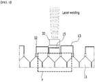
- Fig. 1 is a view for explaining the method of welding an electrode lead in the battery cell stack included in a conventional battery module.
- one or more electrode leads 12 and 13 bent onto a busbar 15 can be welded using a jig 30.
- the material of the busbar 15 is required, and in some cases, plating is required and thus, material costs may increase.
- the space of the region P of Fig. 1 corresponding to the rear face space of the electrode leads 12 and 13 is insufficient, it is difficult to confirm whether the welding surface contact is performed, which makes it difficult to guarantee the welding quality.
- the quality of the bending process can affect the welding quality. Because welding is performed after stacking the battery cells 11, there is a problem that it is difficult to reuse the battery cell 11 if a defect occurs during welding.
- a battery module comprising: a battery cell having an electrode lead protruding from one end part, a cell tray on which the battery cells are mounted, and a busbar mounted on one end part of the cell tray positioned in a direction parallel to the protruding direction of the electrode lead and welded to the electrode lead, wherein the busbar comprises a busbar plate, which is a portion welded to the electrode lead, and a busbar connection part formed by being bent at one end of the busbar plate, and the busbar connection part is bent in a direction perpendicular to a surface of the busbar plate.
- a welding surface of the busbar connection part may be formed toward the width direction of the battery cell.
- the electrode lead may be welded to the busbar plate in the same direction as the stacking direction of the battery cells.
- the battery cell comprises a first battery cell and a second battery cell that are adjacent to each other
- the cell tray comprises a first cell tray and a second cell tray on which the first battery cell and the second battery cell are mounted, respectively, one cell unit including the first battery cell mounted in the first cell tray and the second battery cell mounted in the second cell tray is formed, the cell unit are stacked by a plurality of numbers to form a battery cell stack, and the plurality of cell units may be connected by a single cell unit connection member.
- the cell unit connection member may connect a welding part of the busbar connection part formed in each of the plurality of cell units.
- the battery module may further comprise a busbar connection member that connects a first busbar connection part mounted on the first cell tray and a second busbar connection part mounted on the second cell tray to each other.
- the busbar connection member may be positioned between the cell unit connection member and the busbar connection member.
- the cell units adjacent to each other may be connected to each other by an adhesive member.
- the battery module may further comprise a fixing member formed at one end part of each of the first cell tray and the second cell tray in a width direction.
- a battery pack comprising: the above-mentioned battery module, a pack frame that houses the battery module, and a thermal conductive resin layer that is disposed between the battery module and the bottom part of the pack frame.
- a method of manufacturing a battery pack comprising the steps of: mounting each of the plurality of battery cells on a cell tray, welding an electrode lead protruding from the battery cell to a busbar mounted on the cell tray, connecting different battery cells adjacent to the battery cell by an adhesive member to form one cell unit including at least two battery cells, applying a thermal conductive resin to a lower pack housing having a plurality of module regions to form a thermal conductive resin layer, sequentially inserting the cell units on the thermal conductive resin layer to form a battery cell stack, and connecting busbars mounted on each of the cell trays included in the battery cell stack.
- the electrode lead and the busbar may be welded in the same direction as the stacking direction of the battery cells in a state in which the busbars are arranged along a direction parallel to the protruding direction of the electrode lead.
- a welding surface of the busbar connection part included in the busbar may be connected by one cell unit connection member.
- the busbar connection part may be formed by being bent at one end part of a busbar plate of the busbar that is welded to the electrode lead, and a welding surface of the busbar connection part may be formed toward a width direction of the battery cell.
- the step of connecting busbars mounted on each of the cell trays included in the battery cell stack further comprises forming a busbar connection member that connects the busbar connection parts formed in each of adjacent battery cells to each other, wherein the busbar connection member may be formed between the cell unit connection member and the busbar connection part.
- the method of manufacturing a battery pack may further comprise forming an upper pack housing for covering the battery cell stack.
- the battery cells are unit-welded to the cell tray, only the corresponding battery cells are discarded at the time of occurrence of defect, thereby capable of preventing the problem that the entire cell stack must be discarded.
- the electrode leads are welded without bending, the welding quality can be improved.
- the battery cells can be connected via a connection member in a pack unit without using a busbar frame, thereby simplifying the production process.
- planar when referred to as “planar”, it means when a target portion is viewed from the upper side, and when referred to as “cross-sectional”, it means when a target portion is viewed from the side of a cross section cut vertically.
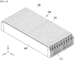
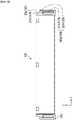
- Fig. 2 is a perspective view illustrating a battery module according to one embodiment of the present disclosure.
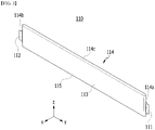
- Fig. 3 is a perspective view of a battery cell included in the battery module of Fig. 2 .
- a battery module 100 includes a battery cell stack 200 in which a plurality of battery cells 110 are stacked.
- the battery cell 110 is preferably a pouch-type battery cell, and may be formed into a rectangular sheet-like structure.
- the battery cell 110 according to the present embodiment has a structure in which two electrode leads 111 and 112 protrude from one end part 114a and the other end part 114b which are disposed on the opposite sides to each other in reference to the cell body 113, respectively. More specifically, the electrode leads 111 and 112 are connected to an electrode assembly (not shown) and protrude from the electrode assembly (not shown) to the outside of the battery cell 110.
- One of the two electrode leads 111 and 112 may be a positive electrode lead 111 and the other may be a negative electrode lead 112. That is, the positive electrode lead 111 and the negative electrode lead 112 can be protruded in opposite directions to each other in reference to one battery cell 110.
- the battery cell 110 can be produced by joining both end parts 114a and 114b of a cell case 114 and one side part 114c connecting them in a state in which an electrode assembly (not shown) is housed in a cell case 114.
- the battery cell 110 according to the present embodiment has a total of three sealing parts, the sealing part has a structure in which it is sealed by a method such as heat fusion, and the remaining other side part may be composed of a connection part 115.
- the cell case 114 may be composed of a laminate sheet including a resin layer and a metal layer.
- Such battery cells 110 may be formed by a plurality of numbers, and the plurality of battery cells 110 are stacked so as to be electrically connected to each other, thereby forming a battery cell stack 200.
- the plurality of battery cells 110 may be stacked along the x-axis direction.
- the electrode leads 111 and 112 can be protruded in the y-axis direction and the -y-axis direction, respectively.
- the battery module 100 according to the present embodiment forms a module-less structure in which the module frame and the end plate are removed.
- the battery module 100 according to the present embodiment may include a side surface plate 600 and a holding band (not shown) instead of the module frame.
- a side surface plate 600 and a holding band (not shown) instead of the module frame.
- the weight of the battery module 100 can be significantly reduced as much as the removed module frame and end plate.
- the battery module 100 according to the present embodiment has an advantage in that re-workability is favorable in the battery pack assembly process due to the removal of the module frame.
- the conventional battery module 10 could not be reworked even if a defect occurs due to the welding structure of the module frame.
- the side surface plate 600 is a plate-shaped member and can be disposed on both side surfaces of the battery cell stack 200 to supplement the rigidity of the battery module 100.
- Such side surface plate 600 has elastic properties and may include a plastic material manufactured by injection molding, and in some cases, a leaf spring material can be applied.
- the holding band is a member that wraps the battery cell stack 200 at both end parts of the battery cell stack 200, and can have the function of fixing the plurality of battery cells 110 and the side surface plates 600 constituting the battery cell stack 200.
- an insulating cover (not shown) can be formed on the front surface and the back surface of the battery cell stack 200 corresponding to the direction in which the electrode leads 111 and 112 protrude.
- the battery cells 110 and the side surface plate 600 included in the battery cell stack 200 are fixed via the holding band, whereby the insulating cover can be easily coupled to the front surface and the back surface of the battery cell stack 200.
- Such a holding band can be composed of a material having a predetermined elastic force, and specifically, a structure of a leaf spring can be applied.
- the electrode leads 111 and 112 and the busbar 500 can be welded in the plane direction.
- the busbar 500 may include a busbar plate 510 and a busbar connection part 520.
- the electrode leads 111 and 112 can be welded to the busbar plate 510, which will be described later.
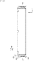
- Fig. 4 is a side view illustrating a state in which the battery cell of Fig. 3 is mounted on a cell tray.
- Fig. 5 is a view of the battery cell of Fig. 4 as viewed along the z-axis direction.
- the battery cells 110 included in the battery module according to the present embodiment are mounted on the cell tray 120.
- a busbar 500 is mounted at one end part of the cell tray 120 positioned in a direction parallel to the protruding direction of the electrode leads 111 and 112.
- the busbar 500 is welded to the electrode leads 111 and 112.
- the electrode leads 111 and 112 can be welded to the busbar 500 in the plane direction in a state in which they are not bent on the basis of the direction protruding from the main body of the battery cell 110.
- the busbar 500 may include a busbar plate 510, and a busbar connection part 520 formed by being bent at one end of the busbar plate 510.
- the busbar connection part 520 is bent in a direction perpendicular to the surface of the busbar plate 510, and a welding surface of the busbar connection part 520 can be formed toward the width direction of the battery cell 110.
- the width direction of the battery cells 110 may be a z-axis direction perpendicular to the stacking direction of the battery cells 110 as shown in Figs. 2 and 4 .
- the longitudinal direction of the battery cell 110 may be a y-axis direction which is the direction in which the electrode leads 111 and 112 protrude.
- Fig. 6 is a side view illustrating a state in which the battery cells adjacent to each other are mounted on each cell tray and then coupled to form a cell unit.
- Fig. 7 is a view of the cell unit of Fig. 6 as viewed along the z-axis direction.
- the battery cell 110 includes a first battery cell 110a and a second battery cell 110b that are adjacent to each other, and the cell tray 120 may include a first cell tray 120a and a second cell tray 120b on which the first battery cells 110a and the second battery cells 110b are mounted, respectively.
- the cell tray 120 may include a first cell tray 120a and a second cell tray 120b on which the first battery cells 110a and the second battery cells 110b are mounted, respectively.
- one cell unit 150 including the first battery cell 110a mounted in the first cell tray 120a and the second battery cell 110b mounted in the second cell tray 120b can be formed.
- the first battery cell 110a and the second battery cell 110b adjacent to each other can be connected to each other by an adhesive member.
- the first busbar 500a includes a first busbar plate 510a and a first busbar connection part 520a
- the second busbar 500b may include a second busbar plate 510b and a second busbar connection part 520b.
- the first busbar connection part 520a and the second busbar connection part 520b can be bent respectively from the first busbar plate 510a and the second busbar plate 510b so as to face each other.
- One of the first electrode leads 111a and 112a protruding from both end parts of the first battery cell 110a may be a positive electrode lead, and the other one may be a negative electrode lead.
- one of the second electrode leads 111b and 112b protruding from both end parts of the second battery cell 110b may be a positive electrode lead, and the other one may be a negative electrode lead.
- the first electrode leads 111a and 112a and the second electrode leads 111b and 112b overlap each other, and the first electrode lead and the second electrode lead overlapping each other can have different polarities from each other.
- the first electrode lead 111a and the second electrode lead 111b having different polarities from each other overlap each other, and at the other end part of the cell unit 150, the first electrode lead 112a and the second electrode lead 112b having different polarities from each other may overlap each other.
- the battery module according to the present embodiment may further include a fixing member 300 formed at one end part of each of the first cell tray 120a and the second cell tray 120b in the width direction.
- the fixing member 300 may function to fix the cell unit 150 in the pack frame in a method of manufacturing a battery pack described later. Specifically, the fixing member 300 may allow the cell unit 150 to be fixed in the pack frame until a thermal conductive resin described later is cured.
- the fixing member 300 may have a hook structure as an example.
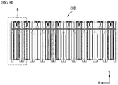
- Fig. 8 is a front view illustrating a battery cell stack formed by stacking a plurality of cell units of Fig. 6 .
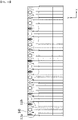
- Fig. 9 is an enlarged view illustrating one cell unit included in the battery cell stack of Fig. 8 .
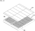
- Fig. 10 is a plan view illustrating the battery cell stack of Fig. 8 .
- Fig. 11 is a plan view illustrating a cell unit connection member formed in the battery cell stack of Fig. 10 .
- the cell units 150 of Fig. 6 can be stacked by a plurality of numbers to form a battery cell stack 200.
- the first busbar plate 510a and the second busbar plate 510b included in the cell unit 150 can each have a structure in which one end part is inclined.
- the first busbar connection part 520a and the second busbar connection part 520b can be bent from one end part of each of the first busbar plate 510a and the second busbar plate 510b so as to face each other.
- a space for bending the first and second busbar plates 510a and 510b can be secured, and the space efficiency can be improved.
- the battery module according to the present embodiment may further include a busbar connection member 540 that connects the first busbar connection part 520a and the second busbar connection part 520b to each other.
- the busbar connection member 540 can electrically connect the electrode leads 111a and 112b formed in each of the battery cells 110a and 110b adjacent to each other. At this time, the busbar connection member 540 may connect the electrode leads 111a and 112b having different polarities from each other.
- the welding quality is improved by welding the electrode leads without bending, and if a defect occurs during welding, only the corresponding battery cell may be discarded. Therefore, it is possible to prevent the problem that even reusable battery cells from the battery cell stack welded after stacking must be discarded.
- busbar connection parts 520a and 520b are bent in a direction perpendicular to the surfaces of the busbar plates 510a and 510b, and a welding surface of the busbar connection parts 520a and 520b can be formed toward the width direction of the battery cells 110a and 110b.
- a busbar connection member 540 may be formed on the welding surface.
- the cell unit connection member 650 may be positioned on the busbar connection member 540.
- the cell unit connection member 650 can electrically connect the plurality of battery cells 110 included in the battery cell stack 200 of Fig. 8 .
- a plurality of cell units may be connected by one cell unit connection member 650.
- the busbar connection member 540 according to the present embodiment may be positioned between the cell unit connection member 650 and the busbar connection parts 520a and 520b.
- the busbar connection member 540 may be omitted and the cell unit connection member 650 may be welded directly to the busbar connection parts 520a and 520b.
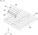
- Figs. 12 to 18 are diagrams illustrating a method of manufacturing a battery pack according to another embodiment of the present disclosure.
- the method of manufacturing a battery pack includes a step of mounting each of a plurality of battery cells 110 on a cell tray 120.
- the cell tray 120 may have a structure that wraps three corners of the battery cell 110, and a busbar 500 can be mounted to the cell tray 120 at the portion corresponding to the electrode leads 111 and 112 of the battery cells 110.
- the busbar 500 mounted on the cell tray 120 and the electrode leads 111 can be welded.
- the busbar 500 and the electrode leads 111 and 112 are welded in the same direction as the stacking direction of the battery cells 110. Since the welding is performed in a state where the adjacent busbar 500 and the electrode leads 111 and 112 are arranged in parallel with each other, it is possible to easily confirm whether the surface contact of the welding object is well performed without obstacles in the surrounding space.
- the second battery cell 110b adj acent to the first battery cell 110a may be connected to each other by an adhesive member 220.
- the adhesive member 220 may be formed so as to have at least one pattern on the side surface of the first battery cell 110a.
- Fig. 13 as an example, it is possible to form the adhesive member 220 in which two patterns are applied to the side surface part of the first battery cell 110a in parallel to each other.
- the first battery cell 110a is mounted on the first cell tray 120a
- the second battery cell 110b is mounted on the second cell tray 120b.
- one cell unit 150 including at least two battery cells including a first battery cell 110a and a second battery cell 110b can be formed.
- a thermal conductive resin can be applied to the bottom part 1111 of the lower pack housing 1110 having a plurality of module regions to form a thermal conductive resin layer 1200.
- the plurality of module regions may be partitioned by a plurality of partition walls 1350 formed in the lower pack housing 1110.
- the cell units 150 can be sequentially inserted onto the thermal conductive resin layer 1200 to form the battery cell stack 200 shown in Fig. 8 .
- Side surface plates 600 can be formed on both surfaces of the battery cell stack 200, respectively. At least one of the side surface plates 600 positioned on both surfaces of the battery cell stack 200 may be first formed in the lower pack housing 1110, and then the cell units 150 may be sequentially inserted.
- Fig. 16 is a diagram in which the battery module 100 including the battery cell stack 200 is completely inserted into the lower pack housing 1110, and Fig. 17 is an enlarged view of region A of Fig. 16 .
- busbars mounted on each of the cell trays included in the battery cell stack can be connected.
- the welding surfaces of the busbar connection parts 520a and 520b included in the busbar can be connected by one cell unit connection member 650.
- a busbar connection member 540 can be formed between the cell unit connection member 650 and the busbar connection parts 520a and 520b.
- the busbar connection member 540 can connect the busbar connecting ports 520a and 520b formed in each of the adjacent battery cells to each other.
- busbar connection member 540 is omitted, and the cell unit connection member 650 may be welded directly to the busbar connection parts 520a and 520b.
- the upper pack housing 1120 can be formed on the lower pack housing 1110 so as to cover the battery module 100 including the battery cell stack.
- the manufactured battery pack 1000 may include a pack frame 1100 for housing the battery module 100 and a thermal conductive resin layer 1200 positioned between the battery module 100 and the bottom part 1111 of the pack frame 1100.
- the battery module 100 includes an insulating cover as described above, and instead may form a module-less structure in which the module frame and the end plate are removed.
- a plurality of such battery modules 100 can be housed in the pack frame 1100 to form the battery pack 1000.
- the pack frame 1100 may include a lower pack housing 1110 and an upper pack housing 1120 that covers the lower pack housing 1110, and a plurality of battery modules 100 may be disposed on the bottom part 1111 of the lower pack housing 1110.
- the lower pack housing 1110 has a plurality of module regions, and the plurality of module regions may be partitioned by a plurality of partition walls 1350 formed in the lower pack housing 1110.
- the partition wall 1350 is formed between battery modules 100 adjacent to each other among the plurality of battery modules 100.
- the thermal conductive resin layer 1200 includes a first thermal conductive resin layer and a second thermal conductive resin layer adjacent to each other, the plurality of module regions include a first region and a second region that are partitioned from each other by a partition wall 1350, the first thermal conductive resin layer is formed so as to correspond to the first region, and the second thermal conductive resin layer may be formed so as to correspond to the second region.
- the first thermal conductive resin layer and the second thermal conductive resin layer may be disposed separately from each other by the partition wall 1350.
- the thermal conductive resin layer 1200 may be formed by applying a thermal conductive resin to the bottom part 1111 of the lower pack housing 1110.
- the thermal conductive resin may include a heat conductive adhesive material, and specifically, may include at least one of silicone material, urethane material, and acrylic material.
- the thermal conductive resin is a liquid during application but is cured after application, so that it can perform the role of fixing the battery module 100 to the lower pack housing 1110. Further, since the thermal conductive resin has excellent heat transfer properties, heat generated from the battery cell 100 can be quickly transferred to the bottom part 1111, thereby preventing overheating of the battery pack 1000.
- the lower surface of the battery cell stack 200 of Fig. 2 can be mounted directly on the thermal conductive resin layer 1200 applied to the lower pack housing 1110.
- the cell tray may have a structure that wraps only the front and rear ends and upper corners of the battery cells 110, and therefore, the lower surface of the battery cell stack 200 may be mounted directly on the thermal conductive resin layer 1200.
- the battery cell stack 200 can be fixed to the lower pack housing 1110 by the thermal conductive resin layer 1200 having adhesive performance.
- the battery pack 1000 according to the present embodiment can form a thermal conductive resin layer capable of fixing the battery module 100, particularly, each battery cell 110 constituting the battery module 100, to the bottom part 1111, thereby improving the structural stability. Further, by eliminating the module frame, the heat generated from the battery cells can be directly transferred from the thermal conductive resin layer to the pack frame, thereby improving the cooling efficiency.
- a heat sink structure may be formed on the pack frame.
- the battery module or the battery pack according to embodiments of the present disclosure as described above can be applied to various devices.
- a device may be applied to a vehicle means such as an electric bicycle, an electric vehicle, or a hybrid vehicle, but the present disclosure is not limited thereto, and is applicable to various devices that can use a battery module.
Landscapes
- Chemical & Material Sciences (AREA)
- Chemical Kinetics & Catalysis (AREA)
- Electrochemistry (AREA)
- General Chemical & Material Sciences (AREA)
- Engineering & Computer Science (AREA)
- Manufacturing & Machinery (AREA)
- Aviation & Aerospace Engineering (AREA)
- Battery Mounting, Suspending (AREA)
- Connection Of Batteries Or Terminals (AREA)
Applications Claiming Priority (2)
| Application Number | Priority Date | Filing Date | Title |
|---|---|---|---|
| KR1020200105144A KR102807505B1 (ko) | 2020-08-21 | 2020-08-21 | 전지 모듈, 이를 포함하는 전지 팩 및 전지 팩 제조 방법 |
| PCT/KR2021/009591 WO2022039399A1 (ko) | 2020-08-21 | 2021-07-23 | 전지 모듈, 이를 포함하는 전지 팩 및 전지 팩 제조 방법 |
Publications (2)
| Publication Number | Publication Date |
|---|---|
| EP4044352A1 true EP4044352A1 (de) | 2022-08-17 |
| EP4044352A4 EP4044352A4 (de) | 2023-08-16 |
Family
ID=80323576
Family Applications (1)
| Application Number | Title | Priority Date | Filing Date |
|---|---|---|---|
| EP21858486.0A Pending EP4044352A4 (de) | 2020-08-21 | 2021-07-23 | Batteriemodul, batteriepack damit und verfahren zum herstellen eines batteriepacks |
Country Status (6)
| Country | Link |
|---|---|
| US (1) | US12431593B2 (de) |
| EP (1) | EP4044352A4 (de) |
| JP (1) | JP7531585B2 (de) |
| KR (1) | KR102807505B1 (de) |
| CN (1) | CN114586226A (de) |
| WO (1) | WO2022039399A1 (de) |
Families Citing this family (6)
| Publication number | Priority date | Publication date | Assignee | Title |
|---|---|---|---|---|
| WO2023239187A1 (ko) * | 2022-06-10 | 2023-12-14 | 주식회사 엘지에너지솔루션 | 배터리 팩 및 이를 포함하는 자동차 |
| KR20240037011A (ko) * | 2022-09-14 | 2024-03-21 | 에스케이온 주식회사 | 배터리 모듈 및 이를 포함하는 배터리 팩 |
| EP4611126A4 (de) * | 2022-12-02 | 2025-10-29 | Lg Energy Solution Ltd | Batteriepack und herstellungsverfahren dafür |
| JP2025539185A (ja) * | 2022-12-02 | 2025-12-03 | エルジー エナジー ソリューション リミテッド | バッテリーパックおよびその製造方法 |
| KR20240082759A (ko) * | 2022-12-02 | 2024-06-11 | 주식회사 엘지에너지솔루션 | Ctp 타입의 고에너지 밀도 전지팩 |
| JP2025537977A (ja) * | 2022-12-02 | 2025-11-20 | エルジー エナジー ソリューション リミテッド | バッテリーパックおよびその製造方法 |
Family Cites Families (22)
| Publication number | Priority date | Publication date | Assignee | Title |
|---|---|---|---|---|
| KR100932227B1 (ko) * | 2005-09-02 | 2009-12-16 | 주식회사 엘지화학 | 이차전지 및 이를 포함하는 전지모듈 |
| JP5098350B2 (ja) | 2007-02-06 | 2012-12-12 | 株式会社Gsユアサ | 電池 |
| EP2672547B1 (de) | 2011-04-26 | 2017-05-31 | LG Chem, Ltd. | Busschiene mit einer neuartigen struktur sowie batteriemodul damit |
| JP2014519153A (ja) | 2012-01-03 | 2014-08-07 | エルジー・ケム・リミテッド | バッテリーパック及びそれに適用されるコネクティングバー |
| JP6009790B2 (ja) | 2012-03-22 | 2016-10-19 | 株式会社東芝 | 電池、組電池、および導電部材 |
| KR20140056835A (ko) * | 2012-11-01 | 2014-05-12 | 주식회사 엘지화학 | 전지모듈 및 이를 포함하는 전지팩 |
| KR101732285B1 (ko) * | 2012-11-09 | 2017-05-02 | 닛산 지도우샤 가부시키가이샤 | 조전지 및 조전지의 제조 방법 |
| KR20150104432A (ko) * | 2014-03-05 | 2015-09-15 | 에스케이이노베이션 주식회사 | 전지셀이 내장된 서브모듈 및 상기 서브모듈로 구성된 전지팩 |
| KR102211192B1 (ko) | 2014-05-30 | 2021-02-02 | 에스케이이노베이션 주식회사 | 단위전지모듈, 전지모듈과 전지팩 및 이들의 제조방법 |
| JP2015230892A (ja) | 2014-06-09 | 2015-12-21 | ソニー株式会社 | 電池モジュール、蓄電装置、蓄電システム、電子機器、電動車両および電力システム |
| KR101806993B1 (ko) | 2014-12-05 | 2017-12-08 | 주식회사 엘지화학 | 전지, 및 이를 포함하는 전지 모듈과 전지 모듈 조립체 |
| US10700317B2 (en) * | 2015-04-13 | 2020-06-30 | Cps Technology Holdings, Llc | Cell to heat sink thermal adhesive |
| KR102082384B1 (ko) * | 2015-08-11 | 2020-02-27 | 주식회사 엘지화학 | 금속 팩 케이스와 열전도 부재를 포함하는 전지팩 |
| GB201523108D0 (en) * | 2015-12-30 | 2016-02-10 | Hyperdrive Innovation Ltd | Battery management system |
| KR102886116B1 (ko) * | 2017-02-08 | 2025-11-14 | 현대모비스 주식회사 | 카트리지형 배터리 셀을 포함하는 배터리 모듈 |
| KR102160276B1 (ko) * | 2017-06-16 | 2020-09-25 | 주식회사 엘지화학 | 배터리 모듈, 이러한 배터리 모듈을 포함하는 배터리 팩 및 이러한 배터리 팩을 포함하는 자동차 |
| KR102484424B1 (ko) | 2018-03-26 | 2023-01-04 | 에이치그린파워 주식회사 | 버스바 내장 카트리지 |
| KR102514123B1 (ko) | 2018-04-19 | 2023-03-23 | 주식회사 엘지에너지솔루션 | 용접을 용이하게 할 수 있는 버스바 프레임 구조를 구비하는 단위 모듈 및 이를 포함하는 배터리 모듈 |
| KR102255487B1 (ko) * | 2018-07-03 | 2021-07-21 | 주식회사 엘지에너지솔루션 | 배터리 모듈, 이러한 배터리 모듈을 포함하는 배터리 팩 및 이러한 배터리 팩을 포함하는 자동차 |
| KR102703855B1 (ko) | 2018-08-21 | 2024-09-05 | 에스케이온 주식회사 | 배터리 모듈 및 이의 제조방법 |
| JP7087959B2 (ja) | 2018-11-27 | 2022-06-21 | トヨタ自動車株式会社 | 組電池 |
| KR102452328B1 (ko) * | 2019-01-10 | 2022-10-11 | 주식회사 엘지에너지솔루션 | 이차전지 및 그 제조방법 |
-
2020
- 2020-08-21 KR KR1020200105144A patent/KR102807505B1/ko active Active
-
2021
- 2021-07-23 EP EP21858486.0A patent/EP4044352A4/de active Pending
- 2021-07-23 JP JP2022521706A patent/JP7531585B2/ja active Active
- 2021-07-23 US US17/770,279 patent/US12431593B2/en active Active
- 2021-07-23 CN CN202180005964.3A patent/CN114586226A/zh active Pending
- 2021-07-23 WO PCT/KR2021/009591 patent/WO2022039399A1/ko not_active Ceased
Also Published As
| Publication number | Publication date |
|---|---|
| US20220294084A1 (en) | 2022-09-15 |
| JP7531585B2 (ja) | 2024-08-09 |
| JP2022551706A (ja) | 2022-12-13 |
| CN114586226A (zh) | 2022-06-03 |
| EP4044352A4 (de) | 2023-08-16 |
| KR102807505B1 (ko) | 2025-05-13 |
| US12431593B2 (en) | 2025-09-30 |
| KR20220023434A (ko) | 2022-03-02 |
| WO2022039399A1 (ko) | 2022-02-24 |
Similar Documents
| Publication | Publication Date | Title |
|---|---|---|
| EP4044352A1 (de) | Batteriemodul, batteriepack damit und verfahren zum herstellen eines batteriepacks | |
| CN113711433B (zh) | 电池模块和包括该电池模块的电池组 | |
| US12482876B2 (en) | Battery pack and device including the same | |
| CN113692672B (zh) | 电池模块、制造该电池模块的方法以及电池组 | |
| EP4024568A1 (de) | Batteriepack und herstellungsverfahren dafür | |
| CN113812035B (zh) | 电池模块、其制造方法以及电池组 | |
| CN114467224B (zh) | 电池模块、包括电池模块的电池组和制造电池模块的方法 | |
| US20210265707A1 (en) | Battery Module and Manufacturing Method Thereof | |
| US12230839B2 (en) | Apparatus and method of manufacturing battery module | |
| EP4020687A1 (de) | Batteriemodul, batteriesatz damit und verfahren zum transport eines batteriemoduls | |
| JP7834853B2 (ja) | バッテリーパックおよびこれを含むデバイス | |
| KR20220017829A (ko) | 전지 모듈, 이를 포함하는 전지 팩 및 전지 모듈 운반 방법 |
Legal Events
| Date | Code | Title | Description |
|---|---|---|---|
| STAA | Information on the status of an ep patent application or granted ep patent |
Free format text: STATUS: THE INTERNATIONAL PUBLICATION HAS BEEN MADE |
|
| PUAI | Public reference made under article 153(3) epc to a published international application that has entered the european phase |
Free format text: ORIGINAL CODE: 0009012 |
|
| STAA | Information on the status of an ep patent application or granted ep patent |
Free format text: STATUS: REQUEST FOR EXAMINATION WAS MADE |
|
| 17P | Request for examination filed |
Effective date: 20220421 |
|
| AK | Designated contracting states |
Kind code of ref document: A1 Designated state(s): AL AT BE BG CH CY CZ DE DK EE ES FI FR GB GR HR HU IE IS IT LI LT LU LV MC MK MT NL NO PL PT RO RS SE SI SK SM TR |
|
| REG | Reference to a national code |
Ref country code: DE Ref legal event code: R079 Free format text: PREVIOUS MAIN CLASS: H01M0050502000 Ipc: H01M0050503000 |
|
| A4 | Supplementary search report drawn up and despatched |
Effective date: 20230714 |
|
| RIC1 | Information provided on ipc code assigned before grant |
Ipc: H01M 50/249 20210101ALI20230710BHEP Ipc: H01M 50/211 20210101ALI20230710BHEP Ipc: H01M 50/516 20210101ALI20230710BHEP Ipc: H01M 50/502 20210101ALI20230710BHEP Ipc: H01M 50/503 20210101AFI20230710BHEP |
|
| DAV | Request for validation of the european patent (deleted) | ||
| DAX | Request for extension of the european patent (deleted) | ||
| STAA | Information on the status of an ep patent application or granted ep patent |
Free format text: STATUS: EXAMINATION IS IN PROGRESS |
|
| 17Q | First examination report despatched |
Effective date: 20250407 |